


JerseyCity Frankie
-
Posts
1,338 -
Joined
-
Last visited
Reputation Activity
-
 JerseyCity Frankie reacted to dafi in HMS Victory by dafi - Heller - PLASTIC - To Victory and beyond ...
Yes,
I dared, the lanyards are secured :-)
XXXDAn -
JerseyCity Frankie reacted to JesseLee in Scottish Maid by JesseLee - FINISHED - Artesania Latina - 1:50
Jumping around a bit. Shaped a few of the yards & started on some of the trusses. The foreyard truss is wood attached with metal pins & CA glue. Will add bands later. The lower fore topsail yard truss I made out of metal wire. Banded it onto the yard with flattened metal wire wrapped around & hooked into notches in the yard. CA glued them, filled in the area where the wire notched into the yard, filed it down to match the rest of the band & painted them. This was a little complicated, wrapping CA coated paper would have done & looked just as good but wouldn't have held the truss very strong.
-
JerseyCity Frankie reacted to JesseLee in Scottish Maid by JesseLee - FINISHED - Artesania Latina - 1:50
here are some shots that show how the supplied pins looked & fitted & how they look & fit now after making them thinner...
-
JerseyCity Frankie reacted to testazyk in Rigging arrangement in Crows nest
Hi Newton, I can't help with your specific inquiry but on the subject of nomenclature, I've heard two theories about the source of the term "crows nest."
One was that crows will fly directly toward land and that sailors kept crows and released them to find the direction of the nearest land. Presumably the crows were kept or released from the tops and that led to the term.
I find that doubtful but no more plausible than the other theory. On some 17th century ships the bottom shrouds for the fore and main masts were attached to the top by several smaller lines. The result was called the "crow's foot" and that led to the top being named the "crow's nest."
Probably more information than you need/want and I'm sure someone out there knows the definitive answer, but it's interesting how these stories crop up.
-
JerseyCity Frankie reacted to O.Klausen in 17th or 18th century rigging on danish fregate of 1709?
Hello,
Just registered here, but been reading the forums for a while and thanks for all usefull information so far! I am definitely a newbie so it is with great reverence I post my first thread..
I am thinking of building a model of a Danish-Norwegian fregate, "Höyenhald" or "Raae" by danish constructor Judichaer. Raae was launched 1709 and in service until 1751 (plans available at orlogsbasen.dk, click "database" and "simpel" or "advanced" search to find the ships).
My question is what type of rigging to use. 17th century or 18th century? On the attached file you see the Raae with a sprit topmast and jackstaff, but being in service until 1751 (1754 for the Höyenhald) they must have been re-rigged at some point with more modern rigging? In England it seems like the change was made between 1710-1720. But perhaps the danes were a little slower in adapting it? I have noticed that some danish ships (and french) use Lateen sails well into the 18 century when english ships from similar years use gaff riggs.
Oystein Klausen Norway
-
JerseyCity Frankie reacted to Omega1234 in Ingomar by Omega1234 - FINISHED - 1/278 - Hereshoff designed schooner
Hi all. The original deck was really looking sub-standard and was really getting me down! The more I did to it to fix it, the worse it got. So, I ditched it overboard and built a new one; this time, I left even more of the deck exposed for the internals to be seen.
Hope you enjoy the photos. The first photo has the old deck next to it (destined for the scrap wood pile). The other photos show the bulkeads glued in place, in readiness for the cabins, etc to be built around them.
-
JerseyCity Frankie reacted to Omega1234 in Ingomar by Omega1234 - FINISHED - 1/278 - Hereshoff designed schooner
Hi everyone! Back again. Progress has been slow, but, I've started on the internal bulheads. This is the part that I really love, because I always see it as a real challenge to try to fit in as much detail as possible, yet being mindful of how small everything will be. Nonetheless, that's the fun of it, isn't it?
Pictured below are the bulkheads, with their panelling and doorways cut out ( in readiness for the doors). Some photos show the bulkheads temporaily sitting in their respective pats of the hull. This gives you some indication of how it's all coming together.
Pls bear in mind that some of the bulkheads such those of the galley and crews quarters will be painted white; whilst the staterooms and grand saloon will be done in wood, reminiscent of the rich panelling and decor of a luxurious mega yacht of its day.
The deck has also been nearly completed. It now features the diagonal bracing which Hereshoff would have designed to give the steel hull additional strength.
By the way, there's still a lot of cleaning up and finessing to be done, especially to the underside of the deck which look a bit rough at this stage. All in good time, though.
I hope you enjoy the progress so far!
-
 JerseyCity Frankie got a reaction from Mike 41 in USS Pennsylvania 1837 by Mike 41 - Scale: 1:64 - Cross-Section
I'm so glad someone built a model of the Pennsylvania. Such an odd wrinkle of American maritime history, the story of this ships "career" deserves better distribution in the literature than it gets. I think there is a Currier and Ives print of her? Another reason I like this build is the nature of the cross section. A few years ago I built a very detailed model of the mast of a frigate that stands, with its base, 8' high. I have long contemplated building the section of hull contiguous with the shrouds associated with the mast. As it is now, the mast is stepped on a purpose built wooden stool and the model starts with the deadeyes and goes up but there is absolutely no framing planking or deck furniture of any kind, just the wooden stool.
-
JerseyCity Frankie reacted to Mike 41 in USS Pennsylvania 1837 by Mike 41 - Scale: 1:64 - Cross-Section
This is the model as she sits now.
-
JerseyCity Frankie reacted to Mike 41 in USS Pennsylvania 1837 by Mike 41 - Scale: 1:64 - Cross-Section
This is a few more photos of the mast.
-
JerseyCity Frankie reacted to Pete Jaquith in Pre Rigging the Tall Ship Model
Pre-Rigging the Tall Ship Model
By Peter Jaquith
Some ship modelers prefer to erect the masts, spars, and rigging in much the same sequence period ships were rigged (e.g. lower masts, lower shrouds, top masts, topmast shrouds, etc.). Other ship modelers pre-rig the masts, spars, and sails with blocks and standing/running rigging components before final installation on the model. The following notes describe the pre-rigging process as applied to the construction of my Topsail Schooner “Eagle” of 1847 build:
Rigging Strategy – My rigging strategy for the Topsail Schooner “Eagle” build was to install all possible eyebolts, blocks, standing/running rigging lines and components on the masts, spars, and sails prior to erection onboard the model. Where appropriate, I constructed sail/spar assemblies to further complete rigging work on the bench prior to erection onboard the model.
Rigging Planning – Using a markup of the ship’s rigging plans, each rigging component/rigging line was identified and assigned to its installation stage with due consideration given to maintaining flexibility for onboard adjustment. Once the plan review was completed, check lists were prepared by mast, spar, sail, and sail/spar assembly to track these installations.
Pre-Rigging the Gaffs & Booms – Boom and gaff pre-rigging included yard bands, eyebolts, parrel assemblies, blocks, and standing/running rigging lines associated with the respective spar. Examples include boom sheet assemblies, boom sheet, boom topping lift, boom footropes, gaff throat and peak halyards, gaff vangs, and gaff topsail eyebolts and blocks.
Pre-Rigging the Topsail & Lower Yards – Topsail and lower yard pre-rigging included yard bands, eyebolts, parrel assemblies, blocks, and standing/running rigging lines associated with the respective spar. Examples include yard trusses assembly; parrel assembly; jackstays; footropes; brace pendants; halyards; clewline, reef tackle, sheet, and bunt line blocks.
Pre-Rigging the Sails – Sail pre-rigging included running rigging blocks and lines associated with the respective sail. Examples include sail hanks, mast hoops, halyards, downhauls, outhauls, inhauls, tacks, sheets, clewlines, bunt lines, and reef tackle.
Pre-Rigging the Masts – Mast pre-rigging included mast/cap bands, futtock shrouds, mast hoops, boom rest assemblies, mast coats, eyebolts, blocks, and the standing/running rigging associated with the respective mast. Examples include lower yard clevis assembly, lower shrouds, futtock shrouds, topmast shrouds, backstays, main and fore stays, throat and peak halyard blocks/runners, boom topping lift, yard lifts, yard brace blocks/runners, halyards, and buntline blocks.
Sail & Spar Assemblies – The fore and main sails were assembled with their respective booms/gaffs, the fore topsail was assembled on its topsail yard, and the main gaff topsail was added to the aft mast assembly. These assemblies allowed further completion of the running rigging on the bench top vs. onboard the model.
Rigging the Bowsprit & Jibboom – Head rigging (including bobstays, martingale stays, bowsprit guys, jibboom guys, and the bowsprit/jibboom footropes) was installed onboard the model prior to mast installation. Tie in of the fore stay, jib stay, and fore topmast stay will be accomplished after fore mast installation.
Mast Erection & Standing Rigging Completion – Following mast erection on the model; the main triatic and topmast stays were tied off to the fore mast and the lower shrouds, backstays, and fore stays were tied off and secured with deadeyes and lanyards. The head sails were fitted to the fore stays prior to their connection to the bowsprit/jibboom. Additionally, ratlines were installed onboard the model.
Spar, Sail, & Running Rigging Completion – The remaining sails and sail/spar assemblies were installed onboard the model working from aft forward. All the remaining running rigging associated with the sails and spars were tied off and completed in the same sequence. Flags and rigging coils were added after completion of other rigging tasks.
While the pre-rigging strategy described above does require some up front planning; it significantly reduces onboard rigging work resulting in improved access and reduced risk of damage to the model during the rigging process. I find that pre-rigging makes the rigging process far more manageable, although I admit that at one point it seemed as though I would never ever finish all the pre-rigging check list items preceding mast erection.
Pete Jaquith
Shipbuilder
-
JerseyCity Frankie reacted to michaelpsutton2 in Calculating the length of topgallant yards
Last night I found a 1794 copy of Steel on the Historic Naval Ships Association websitehttp://hnsa.org/doc/steel/index.htm%C2'> . It said:
PROPORTIONAL LENGTHS OF YARDS, IN THE ROYAL NAVY.
Main-yard, 8/9 of the main-mast.
Fore-yard, 7/8 of the main-yard.
Mizen-yard, 6/7 of the main-yard.
Main-topsail-yard, 5/7 of the main-yard.
Fore-topsail-yard, 7/8 of the main-topsail-yard.
Mizen-topsail-yard, 2/3 the main-topsail-yard.
Topgallant-yards to 74 gun ships, 2/3 all under, 3/5, of their topsail-yards. Royal-yards, 1/2 of the topsail-yards.
Cross-jack-yard, the same as the fore-topsail-yard.
Spritsail-yard, the same as the fore-topsail-yard.
Spritsail-topsail-yard, the same as the fore-top-gallant-yard.
Studdingsail-yards, 4/7 of their booms.
Driver-yard, the same as the fore-topgallant-yard
This is different than my copy! And certainly different than Lee. It works much better.
And lastly in the section on rigs and sail plans in Sloop of War, the author comments that it is almost impossible to determine with any certainty what the rig of a small vessel may have been. He says the brigs, sloops, snows and brigantines were re-rigged and re-rigged. Further he comments that although many 18th century small craft are recorded as brigantines, not a single set of spar lengths for a brigantine have come to light. It is only in the 19th century that there is documentary evidence for this rig.
-
JerseyCity Frankie reacted to michaelpsutton2 in Calculating the length of topgallant yards
I agree that in there were differences between the theory of masting and what you would find if you could visit the harbor. But what I am seeing is that while most of the masts and other yards seemed to follow the rules in most cases, the topgallant yard lengths listed for specific ship never and i mean never followed the rule.
The sail plan I am attempting to reconstruct would be for the Port Antonio purchased into the Royal navy about 1757. She was two masted. The placement of the masts is not suitable for a ketch, and the arrangement of the lower dead-eyes indicates she was a brig or snow and not a schooner of some kind. Given the date I think a snow more likely. I have incuded a paining by Clevely from 1759 of a what appears to be a similar vessel. Just add a handful of gunports in the waist and some sweep ports as well. She was 67'9" on the deck 22' beam, 9'9" deep and 144 tons. L+B+D =99'6" divided by 2 gives a main mast length of 50' which matches nicely with Steel and the other examples given the "Sloop of War". Lee's book does not have much to say about two masted ships.
The main yard is .9 times the mainmast 45' and we are still good. The topsail yard is about .72 of the main yard or about 32'5". This figure is supported by all of the tables, If the top-gallant should be 1/2 the topsail then we would use 16' or a couple of inches more. But look at the figures in Steels examples. His brig has a main yard of 42', close, a topsail yard of 31'6", still very close... and a top-gallant of 23'6" which is a full 34% bigger than his own guidelines would indicate.
-
 JerseyCity Frankie got a reaction from Gerald Spargo in Charles W Morgan by Gerald Spargo - Model Shipways
With the real Morgan seaworthy and underway again I expect to see a lot more people building her. But I can't imagine many people doing a better job than you have done! You have et the bar very high.
-
-
 JerseyCity Frankie got a reaction from druxey in Spanish flag flown at the Battle of Trafalgar
Imagine the challenges of setting and striking this flag while underway. Its easy enough to picture the Museum staff in the photo having a tough time getting a modern piece of fabric the size of this flag stowed. Now imagine its dusk on the Atlantic and you are instructed to strike this flag and stow it. IF you get it down on deck without fouling, you still have to fold it into a neat package. Look how much floor space it takes up in the photo and then picture the limited amount of space on the poopdeck of the ship.
-
JerseyCity Frankie reacted to md1400cs in Wasa by md1400cs - FINISHED - Corel - 1:75
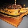
Hello everyone. I am posting 2 pics of my Corel. I want to get it right and then I will add more pics. This is my second build. I completed a Mantua Santa Maria many year ago.
This Wasa has been a lot of fun. I have torn sections out and rebuilt them as I have been able to view so many photos of the real ship. The stern, for example is wrong in the Corel kit. OK let's see if my first pics posts.
-
JerseyCity Frankie reacted to Chuck Seiler in Gun tackel coiling-perfect coils vers some variations Questions
One might say that it doesn't REALLY matter unless you are doing a diorama where all the facets of the model are set in a single moment in time. Otherwise, you may have various pieces of the model displayed in a manner inconsistent with how another part of it would be at the same time; elmtree pumps with the handles installed but nobody manning them, ditto windlasses, guns rigged for sea on one side and run out on the other. This is done to show off some of the features that might not normally be seen, since the model is a display, not a real.
Line coiled on deck as if awaiting the admiral's inspection is not far fetch since the model is 'ready for inspection' by the public. I think any way is correct if that way would have been done at some point on the real ship.
-
 JerseyCity Frankie got a reaction from rybakov in Setting flags - which way does the wind blow?
I love this photo for a lot of reasons. here it serves well to illustrate the flags position in relation to the square sails and the point of sail the ship is on. In this case the ship is being sailed as close to the wind as possible, she is trying to point in the same direction the wind is blowing from. She can't sail directly into the eye of the wind. But if she braces her yards around as far as they can go, so far that the sails are contacting the stays as is visible in the photo, she can get within six points of the eye of the wind. She is said to be "Close Hauled" and in this case she is close hauled on the starboard tack, since the wind is coming over the Starboard side. The flags as you can see are streaming aft and to port.
The flags are ACTUALLY indicating a very very slightly different direction of the true wind since the speed of the ship through the water makes them behave a tiny bit differently than a stationary flag on a fixed point in the wind would behave. So if she was sailing past a rock with a flag on it, the flags on the ship and the flag on the rock would be at very slightly different angles. The one on the rock indicating the True Wind and the ones on the ship indicating the Apparent Wind.
-
 JerseyCity Frankie got a reaction from mischief in dry brushing
Here is my take on drybrushing: You have to think of two spectrums of the condition of the paint you are using. One spectrum is the degree to which the paint is either wet, right out of the container, or dry, where it is set up and hardened. The other spectrum is how much paint is on your brush, with one end of the spectrum being a fully charged brush ready to drip paint, the other being a brush that has given up all it has to give in terms of leaving a paint mark on a surface.
In order to drybrush a surface you should have a solid base coat of one color already on the model and the color you are drybrushing over this should be different in terms of tone or vibrance, usually this color is a lighter color.
Your brush should be a crappy brush, one that has seen the last of its days as a pointy neatly bristled brush. What you want is an ugly mop of a brush a signpainter would forsake, one with bristles like a bad hair day.
You want to get to the far end of each of the spectrums I mentioned above. You want some paint in the bristles of this brush but you don't want that paint very wet nor do you want very much paint charging up the bristles.
You get to this happy place by dipping your brush then wiping the brush on some scrap material, you wipe this mopy brush around on a scrap of cardboard or something until you got 80 to 90% of that paint out of the bristles.
When the brush is hardly leaving any paint marks your just about ready to drybrush on the model.
The feeling you want is that feeling you get when you have a used up felt tip magic marker that is out of ink, you can't write your name with it but you could still ruin a white linen tablecloth if you pressed hard enough.
THIS is the brush you now drag across your model. Depending on where the brush exists straddling both of the two spectrums ( and it will be shifting on these spectrums as you use it) you will see for yourself how hard you need to press and in which direction you need to brush. Lightly at first and brushing in one direction, pressing hard and scribbling in all directions at the end when the paint is all but gone. Its this last stage where you get the best drybrushing effects as the paint is only adhering on the higher points of the surface you are scumbling over.
-
 JerseyCity Frankie got a reaction from bhermann in Setting flags - which way does the wind blow?
I love this photo for a lot of reasons. here it serves well to illustrate the flags position in relation to the square sails and the point of sail the ship is on. In this case the ship is being sailed as close to the wind as possible, she is trying to point in the same direction the wind is blowing from. She can't sail directly into the eye of the wind. But if she braces her yards around as far as they can go, so far that the sails are contacting the stays as is visible in the photo, she can get within six points of the eye of the wind. She is said to be "Close Hauled" and in this case she is close hauled on the starboard tack, since the wind is coming over the Starboard side. The flags as you can see are streaming aft and to port.
The flags are ACTUALLY indicating a very very slightly different direction of the true wind since the speed of the ship through the water makes them behave a tiny bit differently than a stationary flag on a fixed point in the wind would behave. So if she was sailing past a rock with a flag on it, the flags on the ship and the flag on the rock would be at very slightly different angles. The one on the rock indicating the True Wind and the ones on the ship indicating the Apparent Wind.
-
 JerseyCity Frankie got a reaction from popeye2sea in dry brushing
Here is my take on drybrushing: You have to think of two spectrums of the condition of the paint you are using. One spectrum is the degree to which the paint is either wet, right out of the container, or dry, where it is set up and hardened. The other spectrum is how much paint is on your brush, with one end of the spectrum being a fully charged brush ready to drip paint, the other being a brush that has given up all it has to give in terms of leaving a paint mark on a surface.
In order to drybrush a surface you should have a solid base coat of one color already on the model and the color you are drybrushing over this should be different in terms of tone or vibrance, usually this color is a lighter color.
Your brush should be a crappy brush, one that has seen the last of its days as a pointy neatly bristled brush. What you want is an ugly mop of a brush a signpainter would forsake, one with bristles like a bad hair day.
You want to get to the far end of each of the spectrums I mentioned above. You want some paint in the bristles of this brush but you don't want that paint very wet nor do you want very much paint charging up the bristles.
You get to this happy place by dipping your brush then wiping the brush on some scrap material, you wipe this mopy brush around on a scrap of cardboard or something until you got 80 to 90% of that paint out of the bristles.
When the brush is hardly leaving any paint marks your just about ready to drybrush on the model.
The feeling you want is that feeling you get when you have a used up felt tip magic marker that is out of ink, you can't write your name with it but you could still ruin a white linen tablecloth if you pressed hard enough.
THIS is the brush you now drag across your model. Depending on where the brush exists straddling both of the two spectrums ( and it will be shifting on these spectrums as you use it) you will see for yourself how hard you need to press and in which direction you need to brush. Lightly at first and brushing in one direction, pressing hard and scribbling in all directions at the end when the paint is all but gone. Its this last stage where you get the best drybrushing effects as the paint is only adhering on the higher points of the surface you are scumbling over.
-
 JerseyCity Frankie got a reaction from Ponto in dry brushing
Here is my take on drybrushing: You have to think of two spectrums of the condition of the paint you are using. One spectrum is the degree to which the paint is either wet, right out of the container, or dry, where it is set up and hardened. The other spectrum is how much paint is on your brush, with one end of the spectrum being a fully charged brush ready to drip paint, the other being a brush that has given up all it has to give in terms of leaving a paint mark on a surface.
In order to drybrush a surface you should have a solid base coat of one color already on the model and the color you are drybrushing over this should be different in terms of tone or vibrance, usually this color is a lighter color.
Your brush should be a crappy brush, one that has seen the last of its days as a pointy neatly bristled brush. What you want is an ugly mop of a brush a signpainter would forsake, one with bristles like a bad hair day.
You want to get to the far end of each of the spectrums I mentioned above. You want some paint in the bristles of this brush but you don't want that paint very wet nor do you want very much paint charging up the bristles.
You get to this happy place by dipping your brush then wiping the brush on some scrap material, you wipe this mopy brush around on a scrap of cardboard or something until you got 80 to 90% of that paint out of the bristles.
When the brush is hardly leaving any paint marks your just about ready to drybrush on the model.
The feeling you want is that feeling you get when you have a used up felt tip magic marker that is out of ink, you can't write your name with it but you could still ruin a white linen tablecloth if you pressed hard enough.
THIS is the brush you now drag across your model. Depending on where the brush exists straddling both of the two spectrums ( and it will be shifting on these spectrums as you use it) you will see for yourself how hard you need to press and in which direction you need to brush. Lightly at first and brushing in one direction, pressing hard and scribbling in all directions at the end when the paint is all but gone. Its this last stage where you get the best drybrushing effects as the paint is only adhering on the higher points of the surface you are scumbling over.
-
 JerseyCity Frankie got a reaction from Ulises Victoria in dry brushing
Here is my take on drybrushing: You have to think of two spectrums of the condition of the paint you are using. One spectrum is the degree to which the paint is either wet, right out of the container, or dry, where it is set up and hardened. The other spectrum is how much paint is on your brush, with one end of the spectrum being a fully charged brush ready to drip paint, the other being a brush that has given up all it has to give in terms of leaving a paint mark on a surface.
In order to drybrush a surface you should have a solid base coat of one color already on the model and the color you are drybrushing over this should be different in terms of tone or vibrance, usually this color is a lighter color.
Your brush should be a crappy brush, one that has seen the last of its days as a pointy neatly bristled brush. What you want is an ugly mop of a brush a signpainter would forsake, one with bristles like a bad hair day.
You want to get to the far end of each of the spectrums I mentioned above. You want some paint in the bristles of this brush but you don't want that paint very wet nor do you want very much paint charging up the bristles.
You get to this happy place by dipping your brush then wiping the brush on some scrap material, you wipe this mopy brush around on a scrap of cardboard or something until you got 80 to 90% of that paint out of the bristles.
When the brush is hardly leaving any paint marks your just about ready to drybrush on the model.
The feeling you want is that feeling you get when you have a used up felt tip magic marker that is out of ink, you can't write your name with it but you could still ruin a white linen tablecloth if you pressed hard enough.
THIS is the brush you now drag across your model. Depending on where the brush exists straddling both of the two spectrums ( and it will be shifting on these spectrums as you use it) you will see for yourself how hard you need to press and in which direction you need to brush. Lightly at first and brushing in one direction, pressing hard and scribbling in all directions at the end when the paint is all but gone. Its this last stage where you get the best drybrushing effects as the paint is only adhering on the higher points of the surface you are scumbling over.
-
JerseyCity Frankie got a reaction from popeye2sea in Setting flags - which way does the wind blow?
I love this photo for a lot of reasons. here it serves well to illustrate the flags position in relation to the square sails and the point of sail the ship is on. In this case the ship is being sailed as close to the wind as possible, she is trying to point in the same direction the wind is blowing from. She can't sail directly into the eye of the wind. But if she braces her yards around as far as they can go, so far that the sails are contacting the stays as is visible in the photo, she can get within six points of the eye of the wind. She is said to be "Close Hauled" and in this case she is close hauled on the starboard tack, since the wind is coming over the Starboard side. The flags as you can see are streaming aft and to port.
The flags are ACTUALLY indicating a very very slightly different direction of the true wind since the speed of the ship through the water makes them behave a tiny bit differently than a stationary flag on a fixed point in the wind would behave. So if she was sailing past a rock with a flag on it, the flags on the ship and the flag on the rock would be at very slightly different angles. The one on the rock indicating the True Wind and the ones on the ship indicating the Apparent Wind.