shipmodel
-
Posts
941 -
Joined
-
Last visited
Content Type
Profiles
Forums
Gallery
Events
Everything posted by shipmodel
-
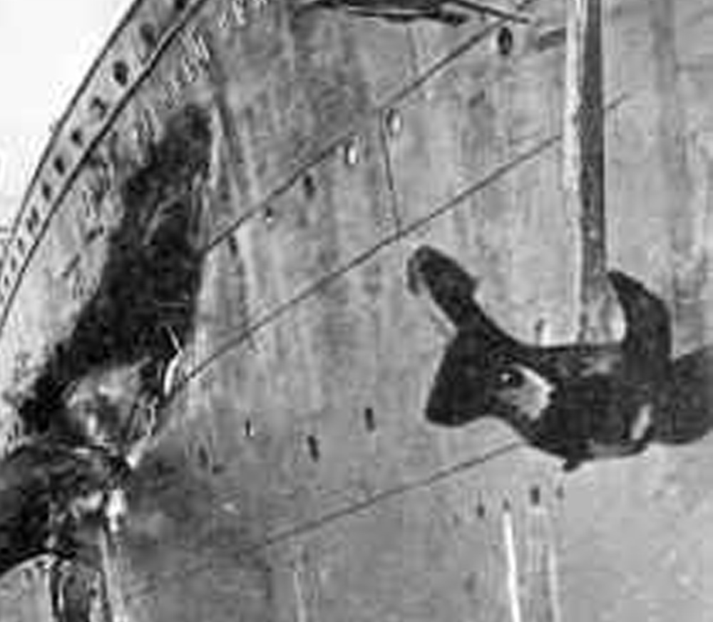
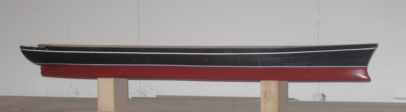
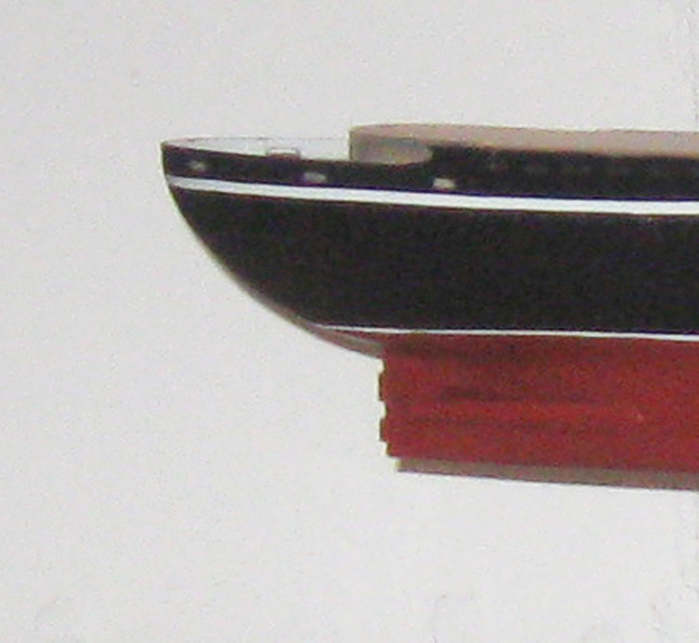
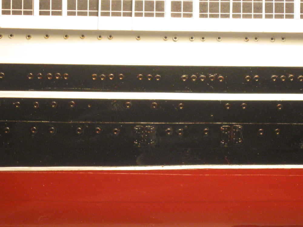
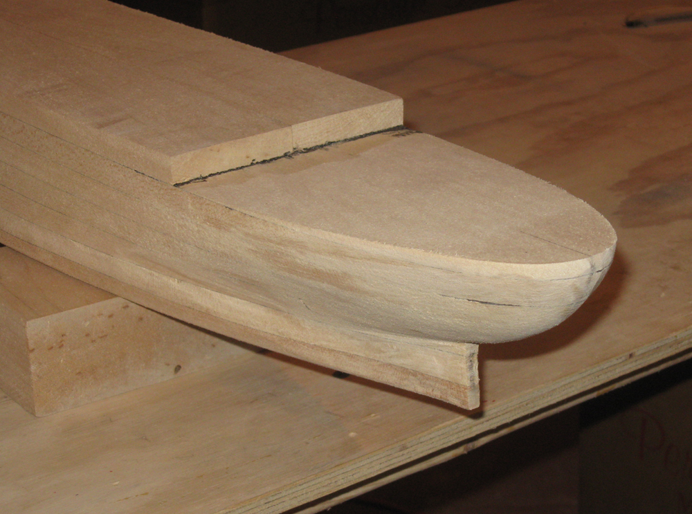
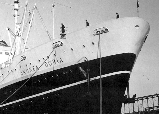
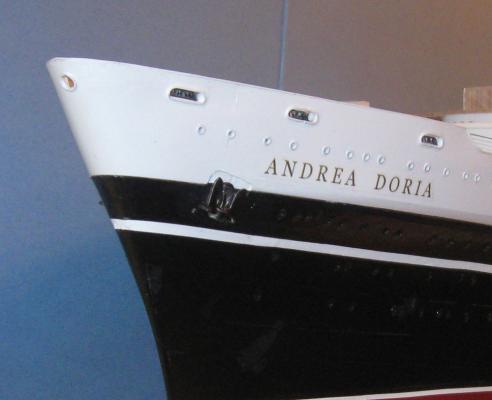
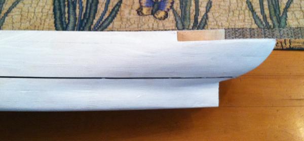
 I took the hull photo and enlarged it in Photoshop. Maybe it is a bit clearer. Dan
- 2,625 replies
-
- 5
-

-
- kaiser wilhelm der grosse
- passenger steamer
- (and 1 more)
-
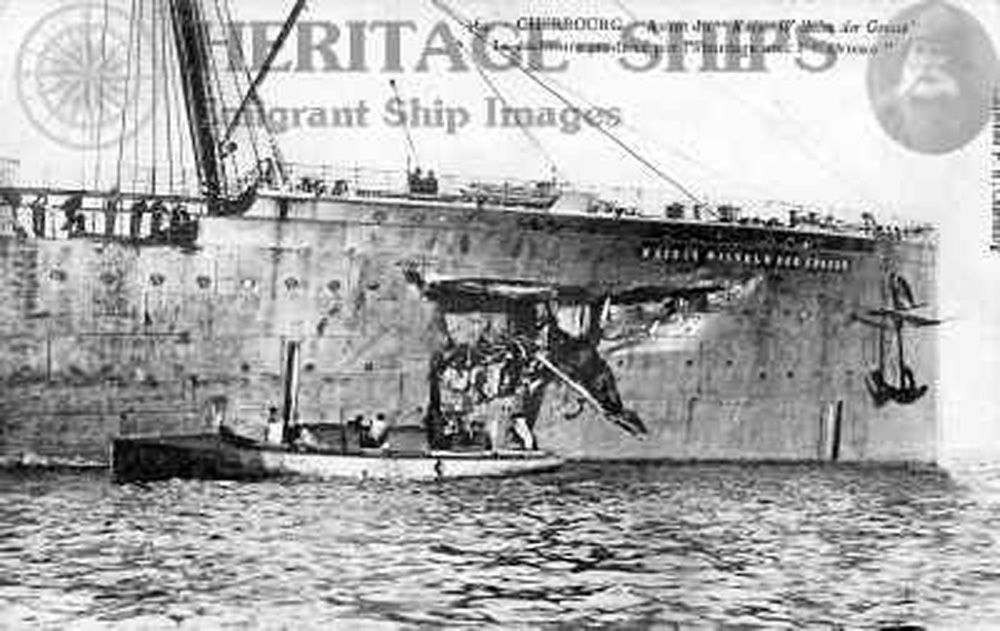
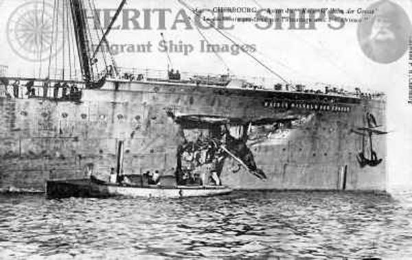
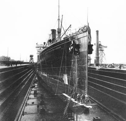
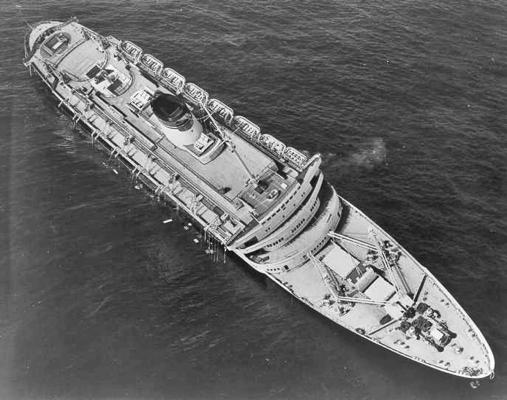
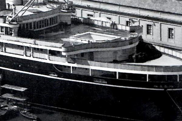
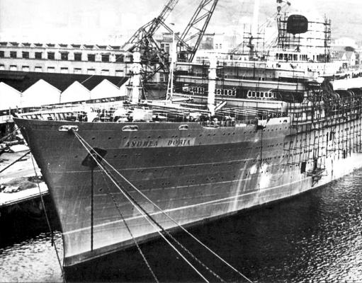
Hi Nils - A great build. I am enjoying the log and your techniques immensely. Lots here to tuck into my toolbox. I did have a question about the in/out hull plating that you are contemplating. I took a quick look through the internet for images of KWdG and everything I found looks like she was flat plated without any rivet heads showing. Maybe you don't have to go through the effort. Here is the best photo I found, with her in drydock. There are certainly strakes of plates, but I can't see the raised edges that you get from overlapping plates. And another after the collision with the Orinoco. I'm not an expert here, so feel free to ignore this. Dan
- 2,625 replies
-
- 10
-
-
- kaiser wilhelm der grosse
- passenger steamer
- (and 1 more)
-
Chuck - Really nice deck and windlass. Right up there with your usual award-winning standards. Dan
- 1,051 replies
-
- 6
-
-
- cheerful
- Syren Ship Model Company
- (and 1 more)
-
Hi all, and thanks for the compliments. Greg, the railings are commercial photoetch from Gold Medal Models. Even with my method I could not approach the precision and accuracy of their pieces. Dan
- 108 replies
-
- 3
-
-
- andrea doria
- ocean liner
- (and 1 more)
-
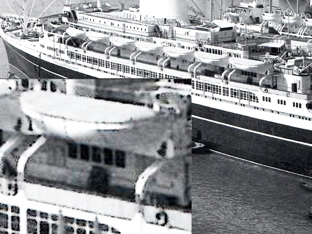
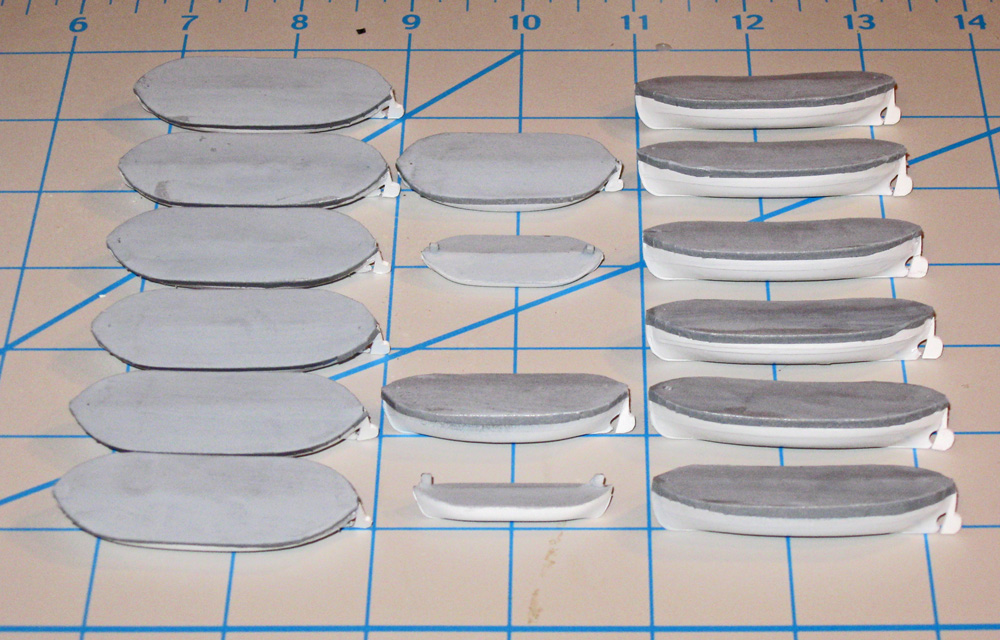
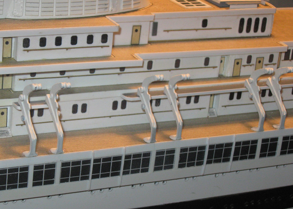
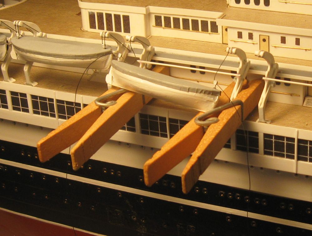
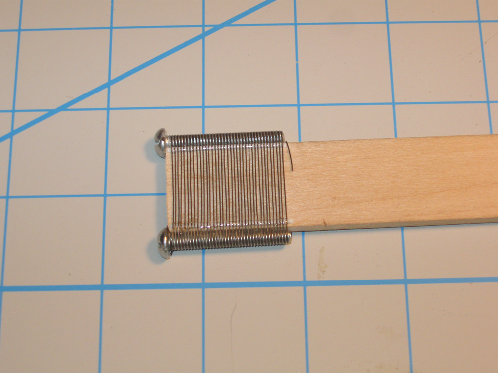
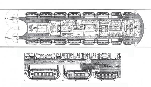
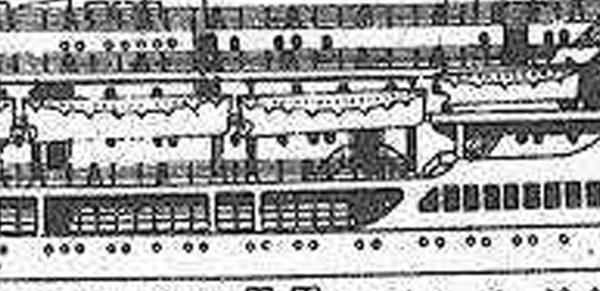
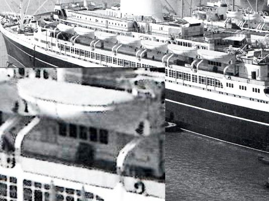
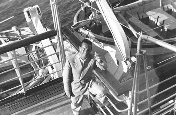
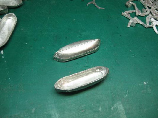
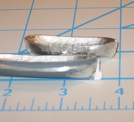
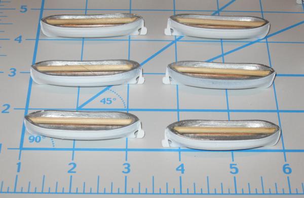
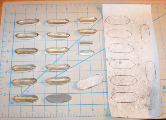
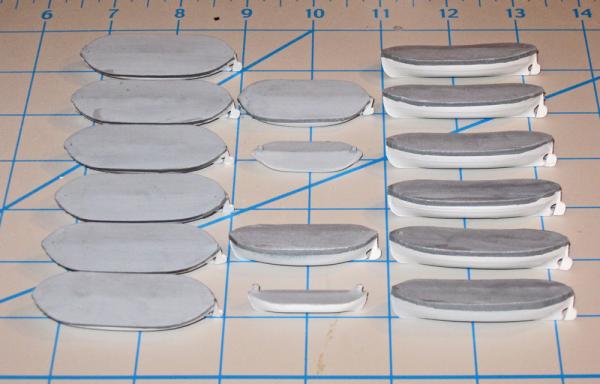
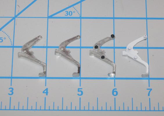
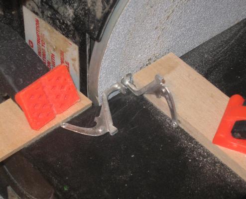
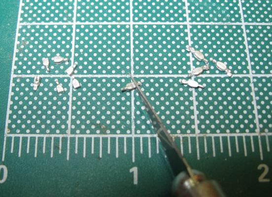
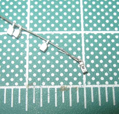
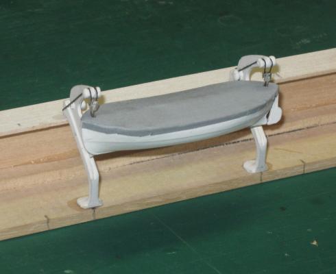
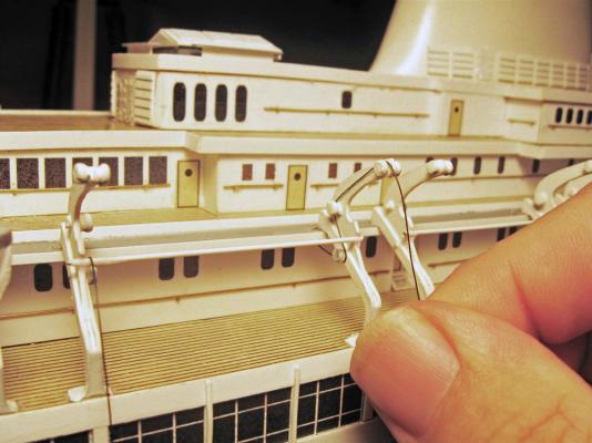
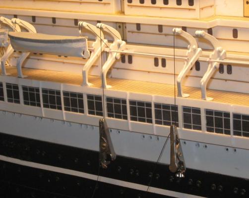
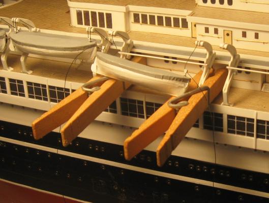
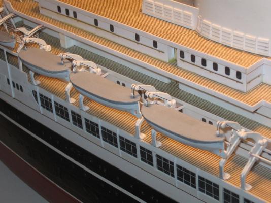
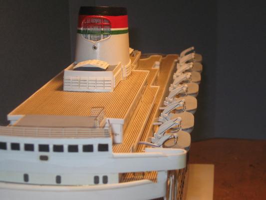
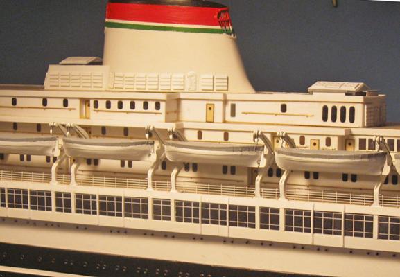
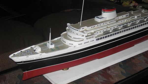
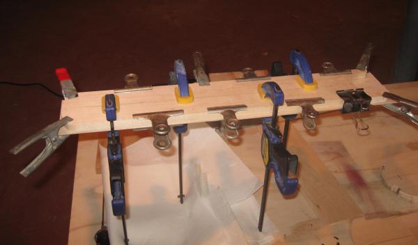
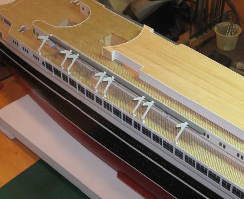
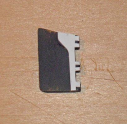
Build Log 9 – lifeboats I got a chance to work on this over the weekend – no grandkids at the house – so here is the next chapter. The long line of lifeboats hanging delicately along the boat deck was a defining feature of most ocean liners after the Titanic. Their prominence and size proudly announced, “We have enough for everybody.” No one seems to have realized that if there was any sort of list the number of available lifeboats would be immediately halved, and that is what happened on the Doria. By the time the passengers could be mustered, only the starboard boats could be launched. Fortunately a number of other ships came to her aid and the passengers were shuttled to safety in several trips. The deck plan shows that there are 8 boats per side: 6 boats 36 feet long, 2 smaller ones 30 feet long, and a pair of small launches mounted on the next deck up that are only 24 feet long. The shape of the davits, which are end-on in both views, cannot be determined. The photographs fill in the details, as usual. Here are the boats of the port side. The enlargement shows a small rudder and propeller on the boat which would make an interesting detail to model. The boat hangs from curved gravity davits of a standard pattern for that era. The davits mount flush with the side of the ship. From above, the high resolution shot that was used for the interior of the funnel also included the lifeboats and davits, giving me much needed information on their size, shape and rigging. I considered leaving the boats open and detailing the interiors, but I couldn’t figure out a reasonable way of making the frames that support the lifeboat covers. It might possibly be doable with 3-D printing, but that is for the future. In the meanwhile I did the best with the available materials and my current techniques to make realistic covered boats. I hope that I succeeded. This guy seems to like my chances. Scaled down, the 36’ boat has to be 2 1/8” long. The 30’ boat is 1 7/8”, and the 24’ launch is 1 ½”. Fortunately, Bluejacket had castings in the blunt, double-ended style that I needed. But they needed some work to clean them up and make them accurate. Bluejacket also had reasonably accurate castings for the gravity davits, and they are in a pile in the upper right. The first task was to carve a counter under the stern with grinding bitts. The deadwood area was thinned and a half circle cutout was ground where a propeller would be mounted. The sternpost was flattened and a bit of plastic for the rudder was cut out and attached. Some flash and rough spots on the hulls were ground smooth, as was the sheer rail. The boats were turned upside down and given a coat of primer and two coats of gloss white. At this point I tried to make up propellers from sheet brass, but they were just beyond my limits and I never did get any that were acceptable, so they were left off. Down the center of the boat is the support for the lifeboat cover. I wanted it rounded so there would not be a crease in the final cover. It would also anchor the lifting blocks for the davits, so it had to be relatively strong. A section of bamboo skewer fit the bill exactly. Each was cut, trimmed and secured with epoxy. To make the covers I traced around one of the 36’ boats onto scrap paper. The image was scanned and imported into the computer where the lines and curves were cleaned up with a drawing program. Then it was enlarged 10% to make a pattern that was about 1mm larger than the top of the boat in all directions. The enlarged shape was copied and pasted 12 times to the same file layout. Two shorter shapes were added for the 30’ boats. The castings for the 24’ boats were solid, so no separate covers were needed. This multiple image was printed out onto acid-free paper. The reverse side of the paper was primed and painted a medium grey. The covers were cut out, bent slightly in the center, and glued flat to the tops of the boats with white PVA. When the glue dried the edges that stuck out were softened with water until they could be folded down the sides of the boats, with a nip and tuck here and there as needed, then secured with glue. Here is the complete set of 16 boats. It was during this process that I realized that the whole sketching, scanning, printing procedure was unnecessary. Once a piece of the painted cover paper was glued down to the boat’s sheer, I could have simply trimmed away the excess with scissors, leaving a 1mm rim all around that would fold down as before. Oh well, nothing lost but some time and effort, and I gained a shortcut for the next model. The davits also started as white metal castings. Here is a photo of the evolution of the pieces. On the left is the unchanged casting. Compared to the photographs the upright arm is too wide and not curved enough. Also, when the lower leg is set vertically, as it would be on the ship, the arm leans back too far and the boat would not hang on the proper line. The second davit has had the inside of the arm ground away to thin it and make the curve. The support leg and foot have been ground down at right angles to each other. The third has pulleys made of ceramic beads, and the last has been primed and painted. Getting the leg and arm to align was quickly done by clamping wooden guides to the table of the disc sander. The leg of the davit piece was first ground with the end of the arm against the guide as a pivot, insuring that the face of the leg would line up with it. Then the davit was turned up and held against the guide as the bottom of the foot was gently ground at a right angle to the leg. Next the pulleys were added. Three were needed on the ‘inside’ face of the davit, the one that faces the lifeboat. Only one was needed on the ‘outside’ face. To get them placed I drilled holes for the three axles and inserted short lengths of iron wire. The rollers were made from the smallest ceramic beads that I could find at the art supply store. They were not all the same precise size, but enough similar beads could be found with central holes that slid over the axles, where they were glued in place. Once the glue was dry the beads were ground down with a stone wheel in the Dremel to flatten their faces and lower their profiles to a uniform height. This was not as easy as I expected. The ceramic beads were quite brittle and almost a third snapped in the first shaping session. I learned to use a smoother grinding drum, a higher rotational speed, and a drop of lubrication, which together solved the problem. Here are several sets finished and mounted in their permanent locations on the boat deck. The last component of the lifeboat setup was the pair of lifting blocks for the boats. These started as castings of single becketed blocks. Photographs seemed to show that the blocks were sort of “U” shaped, so about half of the casting, the becket end, was trimmed with a blade. This left intact the sheave hole and the mounting lug on the other end. The lug holes were opened with a small drill and the blocks were slid onto a long length of iron wire. The end of the wire was folded back around the lug of the last block on the end and crimped tight with a small needle nosed pliers with grooved jaws. The grooves kept the wire from twisting. The folded wires were clipped, leaving a mounting length about 3/16” long. With all the components ready, I made up a test bed. Scrapwood was glued together to the dimensions of the boat deck, deckhouse, and the service walkway that the davits would be mounted to. The spacing of the davits was taken from the model and then transferred to the top of the boat, where holes were drilled into the bamboo cover support. The lifting blocks were installed and the lifting cables were rigged. The ends of the cables go through holes through the walkway on either side of the base of the davit. One of the purposes of the test bed was to determine how to stabilize the lifeboat to keep it from swinging as it hangs by a thread from the davits. The least obtrusive solution that I came up with is a horizontal bar of stiff wire mounted between the davits behind the boat. Experiments showed that for the boat to hang properly this bar had to be set up just below the lugs on the slide, then the boat would hang naturally against it without being forced. Here you can see the bar as I rig a set of inside pulleys. The line that I used for the cables was 0.006” polished nylon thread from Hemminway & Bartlett. It is a great product, but I don’t know if they make it any more. I found a few commercially sized spools years ago in a dusty fabric outlet and snapped them up immediately. The one challenge with this material is that at these scales the thread performs more like steel cable than cotton twine. Springback can be a bitch when I try to go through small holes or around tight corners. Once each inside pulley cable was looped over the three beads it was weighted and tensioned with a small alligator clip so the line hung vertically off the last pulley. A mini-drop of dilute glue locked the line at this point so I could work on rigging the lifeboat without the thread springing loose. To hold the boat as I rigged it I made a simple working stage with a pair of clothespins that were clipped to the davits. The boat rested on them as the first cable was threaded through the first block. The running end was taken over the outside pulley, through the small hole in the walkway next to the base of the davit, and down the side of the hull where it was weighted again with the alligator clip. The second cable was run and set up the same way. The two lines were pulled on gently, like the cords of a window blind and the boat lifted up just like it was being winched. It was set to its proper height where the lines were glued and trimmed. The hang of the boat was adjusted so it was vertical and then locked in place by being glued to the hidden stabilizer bar. After each boat was hung it was also eyeballed to see that the line of boats followed the line of the hull. At the edge of the boat deck there is a railing to keep the passengers from falling overboard. It would have been so much easier to have been able to use one continuous length of the photoetched railing, but the photos clearly show that they were pieced in, so I did the same. How this was done will be part of the next segment. So here she was at that stage, with the camera angle and position such that they create an impression of speed and movement. At least I see it, but I just may be wishing it so. New work has come in, so I may not get to the next segment right away. Till then, Be well Dan

- 108 replies
-
- 14
-
-
- andrea doria
- ocean liner
- (and 1 more)
-
Hi Druxey - Yes, photoetch could have made a more finely detailed set of wires, but I'm not sure that it would have been an easier route. I only needed two of them and they don't already exist out in the commercial world. Having them custom made would have been cost-prohibitive. My past experiences doing it myself with the Micro-mark photoetching system were less than satisfactory. Working my way up that particular learning curve would have taken more time, I think, than the medium-tech solution that I came up with. Not to say that I might give photoetch another try next time around. I do want to learn it at some point. Dan
- 108 replies
-
- 5
-
-
- andrea doria
- ocean liner
- (and 1 more)
-
Andy - That makes more sense than just a reinforcement. When I enlarge the profile plans I can see how the bulwark undercuts them, and they seem to have some spaced brackets that could be what you describe. Thanks. New information is always welcome, even if I never figure out how to model such a small detail. Dan
- 108 replies
-
- 7
-
-
- andrea doria
- ocean liner
- (and 1 more)
-
Ben - Thanks for the info. It makes much more sense now. Putting that together with what can be seen on the plans and photos, do you think that the final appearance is accurate? It is still not too late to make an improvement. Dan
- 108 replies
-
- 5
-
-
- andrea doria
- ocean liner
- (and 1 more)
-
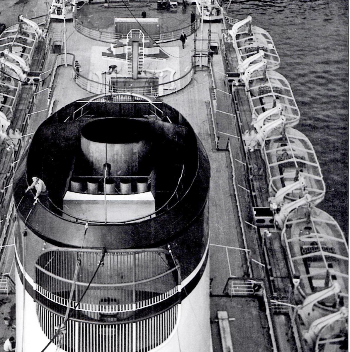
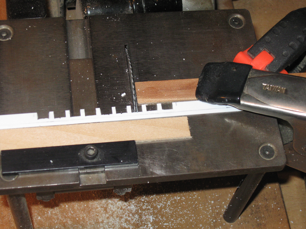
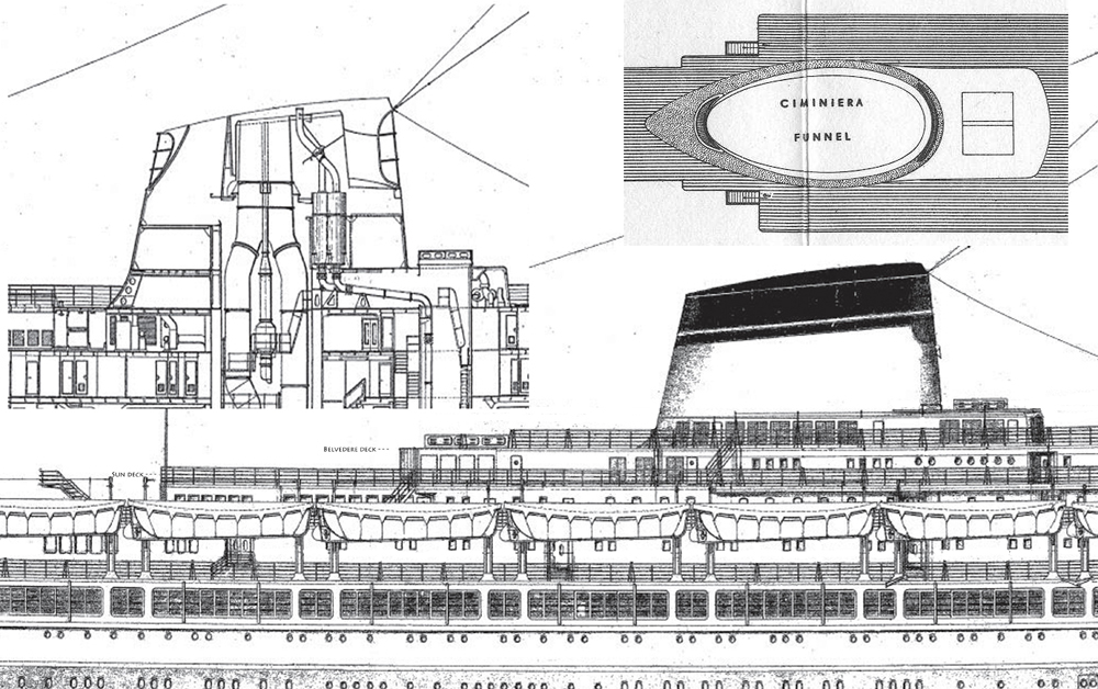
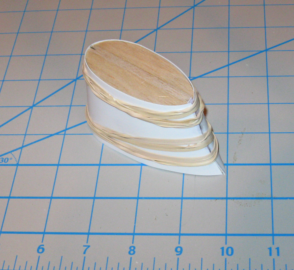
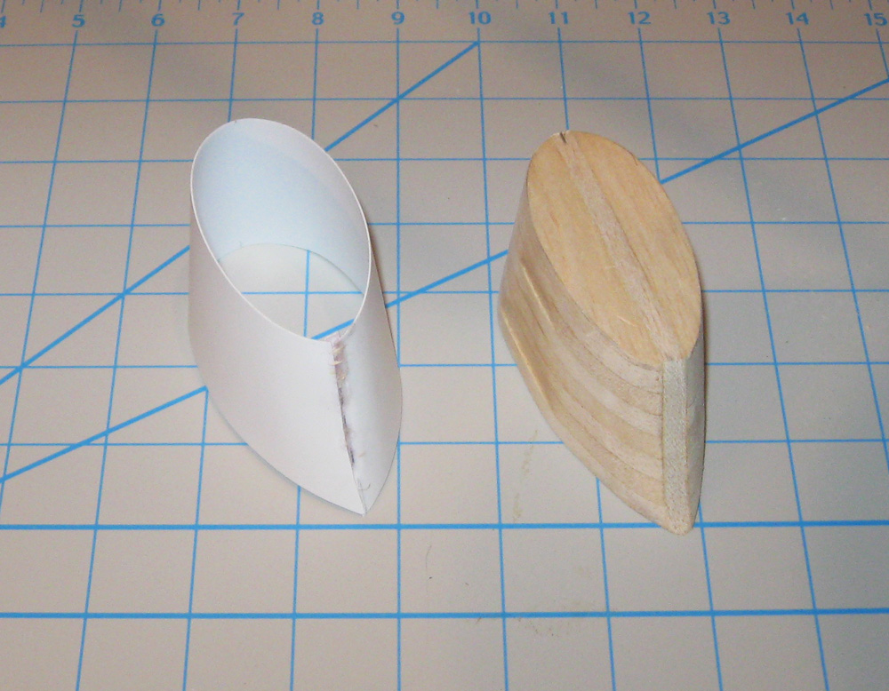
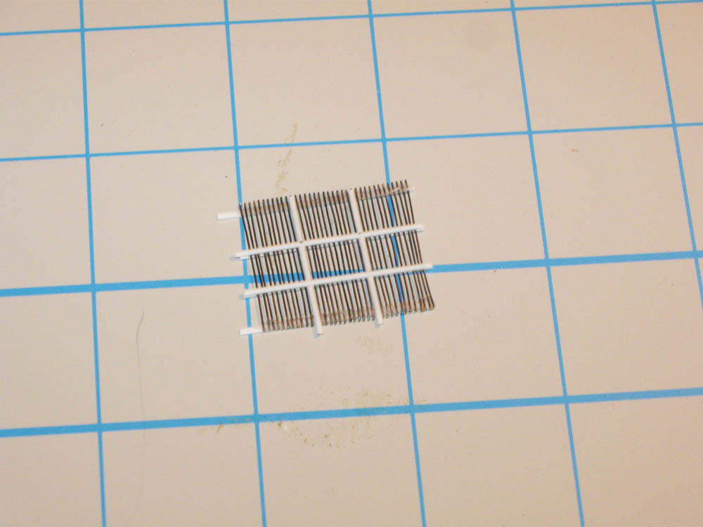
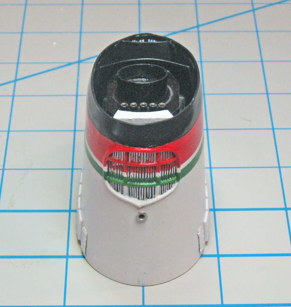
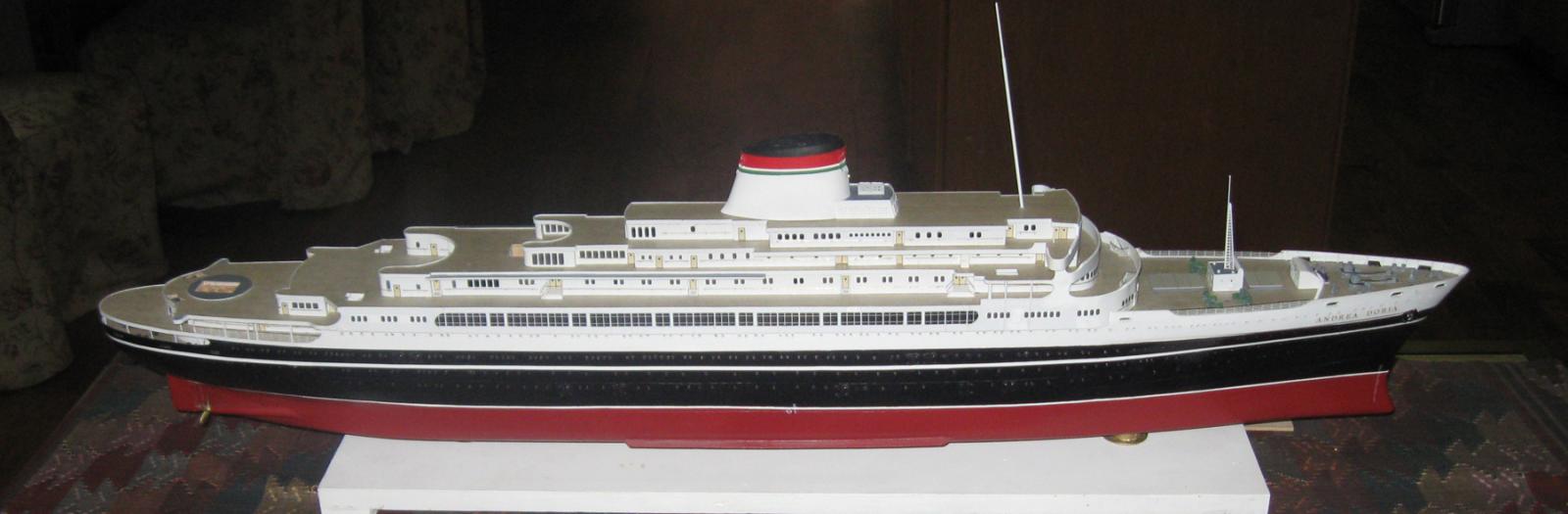
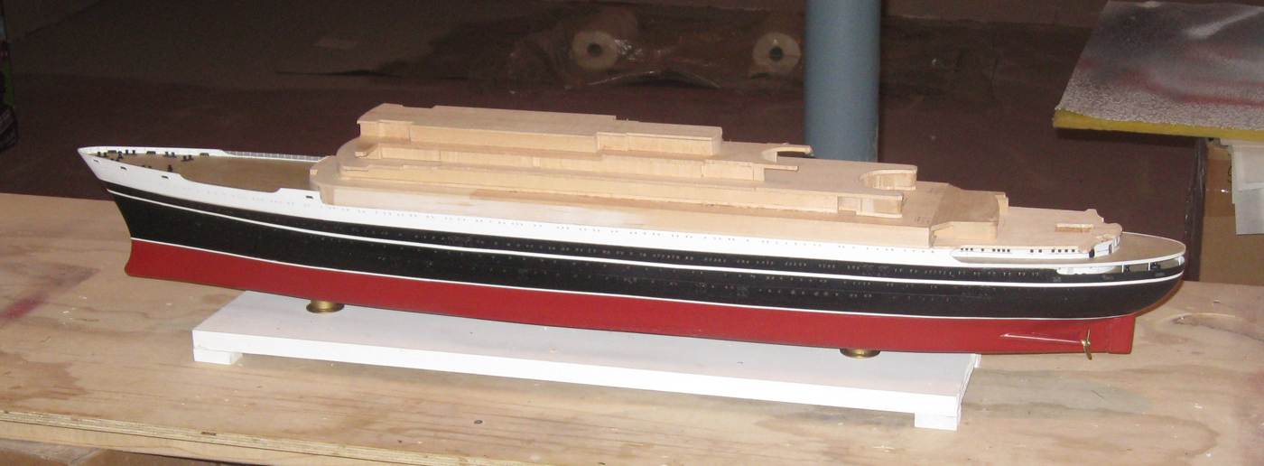
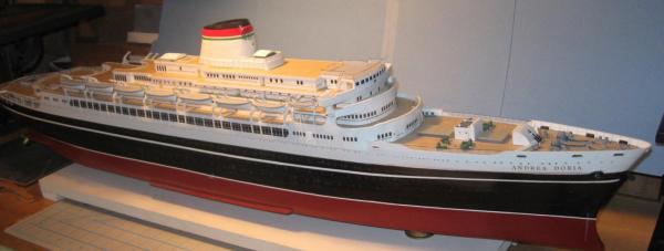
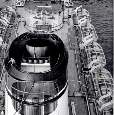
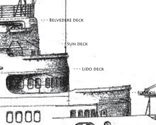
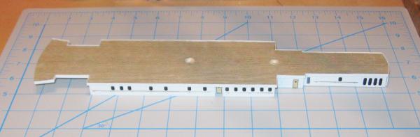
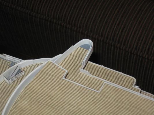
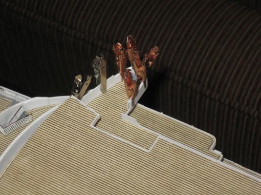
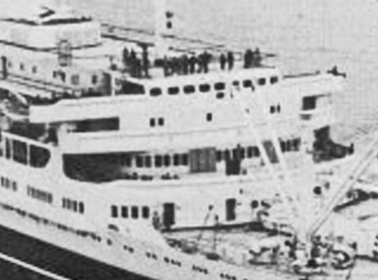
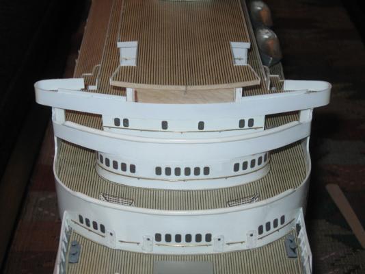
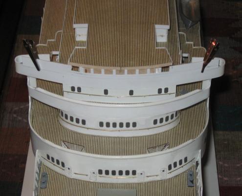
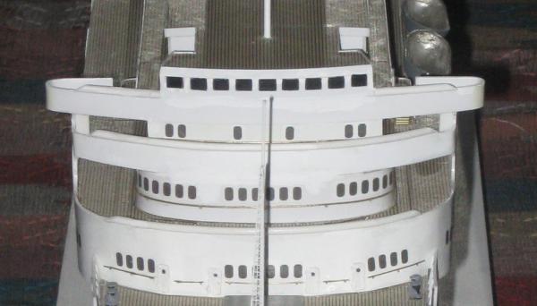
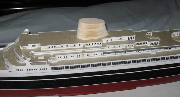
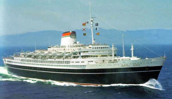
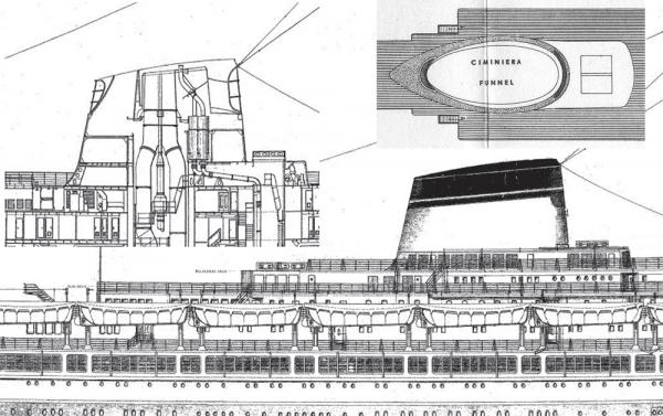
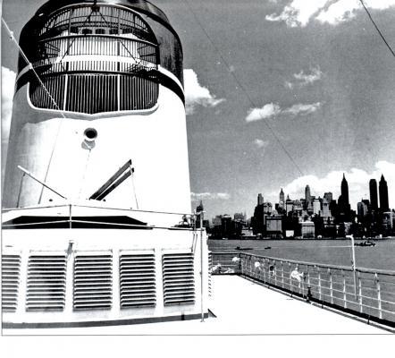
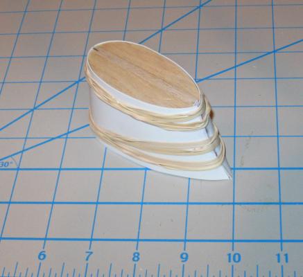
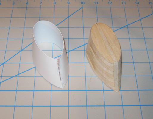
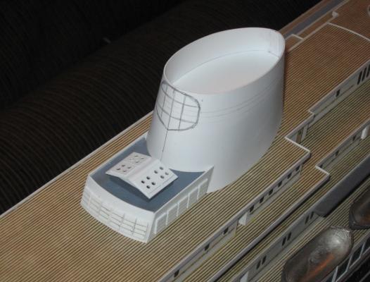
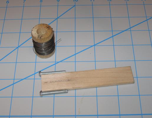
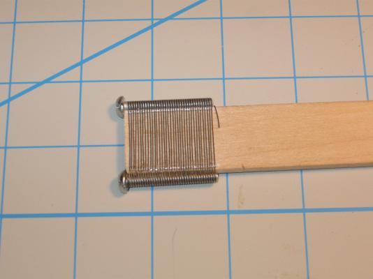
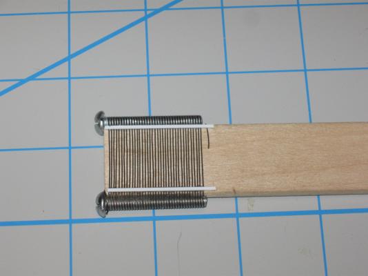
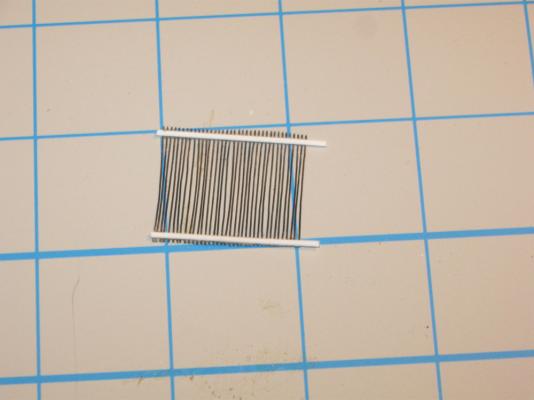
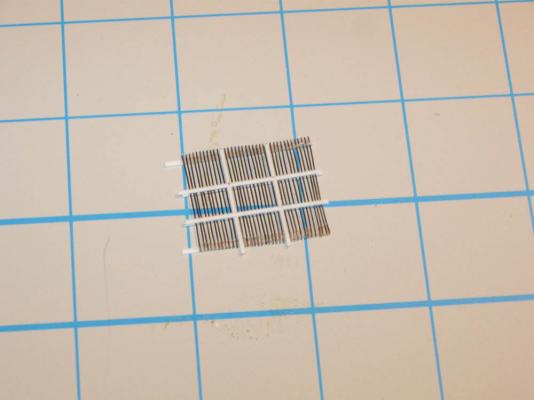
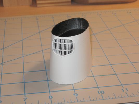
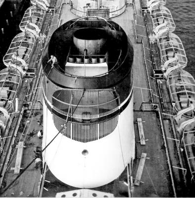
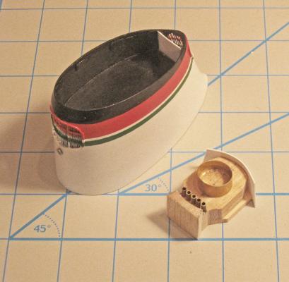
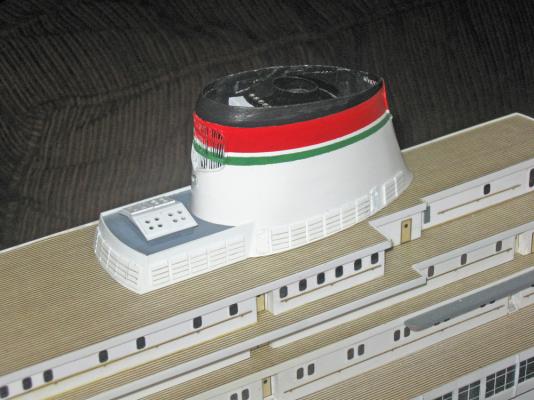
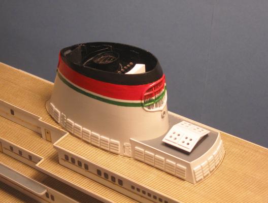
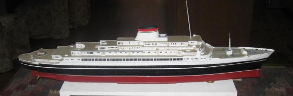
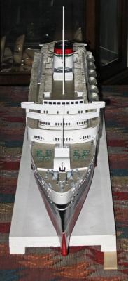
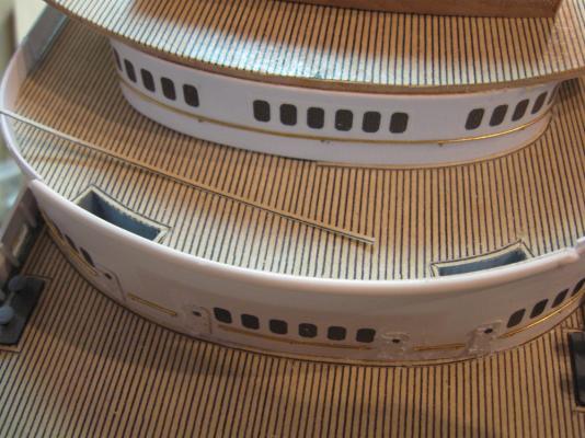
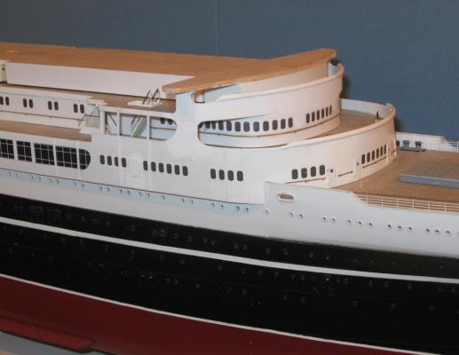
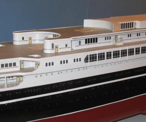
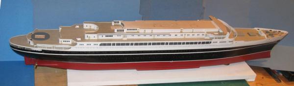
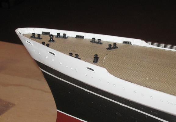
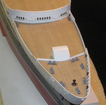
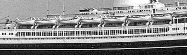
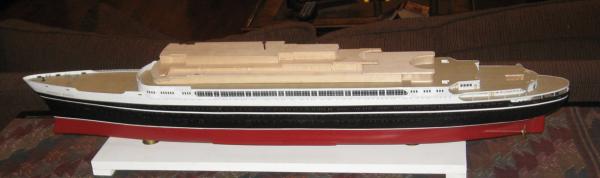
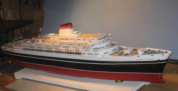
Build log 8 – upper decks, funnel Thanks to all for the likes and comments. I am always so pleased at the generosity and good spirits of our community. I made some time at the computer this week and was able to put together this next chapter. After completing the Boat Deck, I worked steadily upward. The upper deck houses and the thin deck layers were made and detailed to match the plans and photos using the same techniques described in the previous segment. Here is the Sun Deck house topped by the Belvidere Deck layer, the uppermost of the planked wooden decks. The countersunk holes are for long framing screws that will go through most of the superstructure’s layers and help hold the pieces down and immobile forever, or for a general approximation of it. Probably overkill, but I felt better after deciding to install the screws permanently. They will be hidden under the funnel assembly in the final model. From above it is clear how the sheathing around the deck layers cleans up the edges. The irregular shapes of the decks meant that various notches, angles and curves had to be sheathed. Where there were square corners, either inside or out, individual pieces of plastic strip were cut, fitted, trimmed and sanded flush before the next piece was installed. Working outward from the back wall of the notches made fitting easier and hid the joints as much as possible. Most of the curves around the perimeters of the decks are quite gentle, and even where there is a right angle bend the edge strip could be coaxed to take the curve. But the taller bulwarks of the bridge wing had to be laminated to accept the severe reverse bend around the viewing platform. After the plastic was shaped and fitted, a bead of glue was slid between the layers and fed down to cover the mating surfaces, then clamped. These flat-nosed copper electrical clamps are from Radio Shack and are perfect for model construction in these scales since they are so small, hold firmly without marring the plastic, and, best of all, are quite inexpensive. The last piece of sheathing to be made was one of the most complex, the forward face of the bridge. Here is the best photo of this area that I found. In the center there are nine rectangular windows along the bridge house for the ship’s officers. You can also see that the forward bulwarks of the bridge wings have raised parapets with some form of rounded reinforcements, as do those of the Lido and Boat decks. Here are those reinforcements as modeled. I simply made them using half-round strips which were applied to the upper edge of the bulwarks and had their ends shaped and smoothed. The naked wood of the bridge house is ready to be detailed. I decided to try to make the set of bridge windows using only two pieces of sheathing. This would give them more strength than lots of little pieces and would help to get the spacing even. There would be a lower piece which would be notched to create the sides and sills of the windows. A second straight strip would cap off all the windows. Here the lower piece is being notched on the Preac table saw. The plastic is held square to the blade by a support stick and the miter gauge. The depth of the notches is controlled by the stop made of darker wood that is being held in place by the two clamps on the right. The sides of each window frame were cut first, then the area between them nibbled out. Several attempts were made and had to be discarded because the blade took too big a bite and cracked the plastic. I had to go to one of my thinnest blades, move slowly, and even lubricate the blade with a drop of oil. Though I was using a new sharp blade there was some nicking and chipping along the lower edge of the cut as the notches were cleaned out. The slightly ragged lower sills were filed flat and smooth before being test fit in place. Once I had an acceptable piece the face of the bridge house was painted black and the notched piece permanently installed. The bulwark pieces were cut down to proper height and the reinforcements added and faired. Finally the cap strip was installed to complete the windows and all joints were sanded and smoothed. Here is the result in a photo taken just a bit later in the build. At this stage all of the decks and deck houses had been installed with their doors, windows, and handrails. Details such as railings and stairways would be added later. Now I turned to the largest and most eye-catching element of the whole model – the funnel. Many ocean liners have distinctive funnels. RMS Titanic had four of them. SS America and SS United States had rounded caps with flying wings. SS Michelangelo had cage masts like early battleships. Andrea Doria only has one, but it is simply massive, making it a beacon from a long way away with its bright stripes in the colors of a Caprese salad: mozzarella white, tomato red, with a garnish of basil green. That's why they were chosen, right? The plans and drawings show its external appearance with a slanted forward face, rounded and slanted top, and a duck-tailed aft end that fairs into the deck. The plan view shows an extended oval shape that fits into a small deck house on the forward side. The internal machinery is complicated and there are cryptic rounded elements at the forward and aft ends near the top. None of the plans that I have show those rounded elements from the front, but the photographs make it clear that these are grilles with vertical wires that can be seen through. Meanwhile, the deck house is clearly for ventilation, with hatches that open on top and louver panels along the front and sides. Although I knew that the grilles and louvers were too intricate to model at this scale, I determined to try to get as close as I could. The first order of business was to make up the wooden former for the overall shape that you saw earlier. Once I was satisfied I gave it several coats of clear finish and several fine sandings to make it somewhat impervious to cyano glue. A large sheet of plastic was wrapped around the former and roughly trimmed before the final shape could be obtained. The compound curves of the duck-tail shape at the aft side were the most difficult. I had to tack one side of the plastic in place with small dots of glue along the top and bottom of the former before softening the shell with heated air and trimming it carefully along the back seam. The other side was brought around, softened and trimmed to slightly overlap the first, which had been sanded to make an angled scarph joint. The overlap was glued and held in place with rubber bands under fairly heavy tension until the glue hardened and the heated plastic cooled to a hard shell. With a bit of anxiety I wiggled a thin blade between the former and shell, popping each of the small glue spots. Since the glue had not penetrated the wood I managed to free the shell without damage. I have used this temporary spot-weld technique before to make multiple identical parts, but never for such a large structure. The former was cut down below the level of the grilles and topped with a layer of plastic before being reinserted inside the funnel shell. Meanwhile the ventilation house was made up. It has a sloping front face and a skylight type structure on the roof with four hatch covers. Construction was straightforward, using small pieces of HO scale house siding for the louvers. To emphasize their look a shadow line was penciled under each slat and sealed with clear finish. The funnel and deck house were repeatedly test fit till there were no gaps where they met. The grille locations were drawn onto the shell and repeatedly refined till they matched the photos, but I did not cut them out yet. I wasn’t sure that I would be successful in making up the grilles and didn’t want to have to discard the funnel itself. Construction of the grilles began with the vertical wires. I remembered a tip from a long-forgotten modeling article which let me get them straight and evenly spaced. I took two identical machine screws and epoxied them on either side of a piece of thin scrapwood. I wrapped soft iron wire of 0.012” diameter around and around the jig under fairly strong tension, filling each groove of the screws. The wires were secured in place with plastic strips glued to them but not to the jig. The wires were carefully cut on the back side and gently unwrapped from the jig before being trimmed close to the support strips. Although I took as much care as I could, the mechanical stresses of these operations were pretty large, and I had to discard almost a dozen attempts to get the two sets of wires that were needed. The satisfactory pieces were flipped over and half-round moldings were glued to the wires. I used the opportunity to straighten and even up the wires. Now that I had the grilles, the opening was carefully drilled and ground through the shell before the wire piece was bent gently and glued to the inside face. A strip of molding was bent and glued to the outside face. This was as seen in the photos, but also helped hide some of the roughness of the edges of the hole. Compared to this photo of the ship under construction I have to say that the grille is a bit coarse. I would only grade myself B+ for the effort. If I were to do it again I would try for a finer thread on the machine screws and a smaller diameter wire. Accepting that this was the present limit of my talents I added the sloped top to the shell, then masked and brush-painted the red and green bands. A silver foghorn was installed in the front face. Using the plans of the interior machinery and the construction photo I cobbled together a structure of wood, plastic and brass tubing that looks like what I see, although I am still unsure what a number of the pieces actually do. Nonetheless, it was installed in the open top of the funnel. The structure, baffles and pipes were painted flat black while the unidentified angled front piece is white and can be seen through the grille. The funnel was fit and secured to the ventilation house and the deck. Louvers and doors were added at the lower edge as seen in other photos. The final touches were the margin planks added around the curves of the funnel and forward face of the vent house. As my father used to say in similar circumstances, “It looks like it grew there.” Although not everything is perfect, I am happy with this most eye-catching element of the model. With the funnel in place all of the major structural elements were complete. Finally! Here is the model from the port bow angle with the first set of lifeboats waiting their turn. I made up the cargo hatches and second deck house on the bow deck. A tall radio mast is mounted on the centerline of the deck house. I test fit a brass rod painted white as a stand-in for the lookout mast that will rise from the top deck. They were carefully lined up and photographed to test the symmetry of the developing model. Although I had been checking constantly as the build went on, I was still a bit nervous that I had missed something and now would have to backtrack to make corrections. Fortunately, though there are some faults, I was happy with the results of the test. So here is the model ready for the work that I like best, making all of the intricate details that together add up to a “compelling overall impression” of the real ship. Be well Dan


- 108 replies
-
- 19
-
-
- andrea doria
- ocean liner
- (and 1 more)
-
Hi guys - Thanks for the many compliments. I hope the rest of the build is as praiseworthy. Piet - I'm glad that some of my techniques can help you and others with multi-media projects. The mixture of materials that I use is only possible with the advances in glue technology, especially cyanos that don't become brittle or degrade over time. As has been said before, I can only reach so high because I stand on the shoulders of giants. Micheal - I never considered the yellowing of the styrene over time. Thanks for bringing it to my attention. I have not painted most of it, just the odd bit to smooth and blend joints and such. I still have to give the model overall clear coats of finish, gloss for the hull, flat for the decks, so I will look into their UV blocking properties to see if I can find some that will help. Otherwise, I will just tell the customer to keep it out of bright sunlight. Dan
- 108 replies
-
- 5
-
-
- andrea doria
- ocean liner
- (and 1 more)
-
Hi Nils - I thought that I had read through this log, but somehow I missed it. Seriously good work, my friend! Spent an enjoyable two hours with it and found several ideas and techniques that will work their way into my own projects. It was fascinating to see how the techniques that we use are both similar and different because of the scales that we are working in. I am now hooked into the log for instant updates. Dan
- 2,625 replies
-
- 3
-
-
- kaiser wilhelm der grosse
- passenger steamer
- (and 1 more)
-
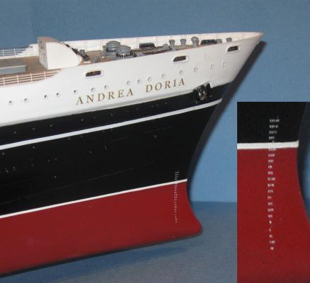
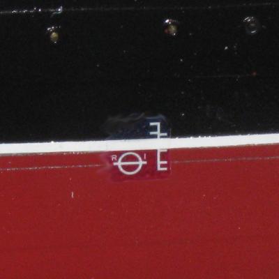
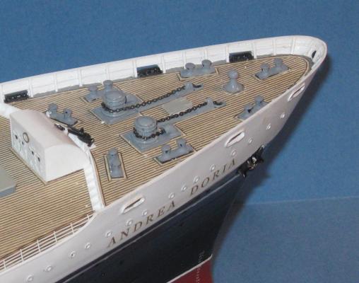
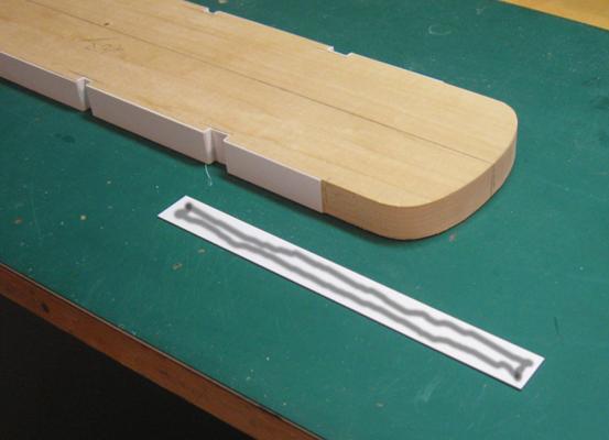
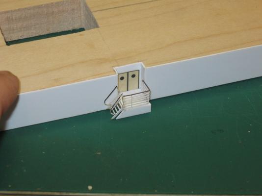
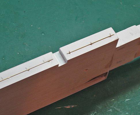
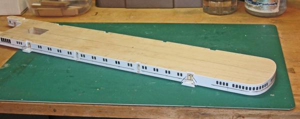
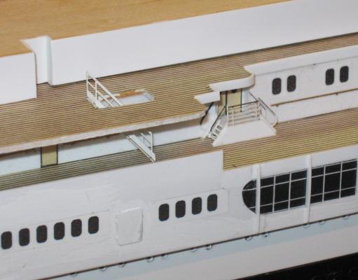
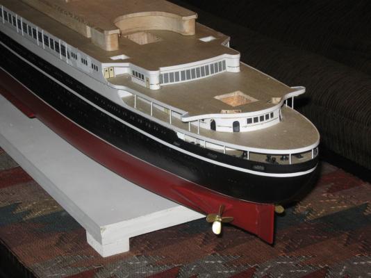
Build log 7 – more bow details, boat deck Thank you Greg and Nils. I'm not sure that the model merits three "wows" yet, but I will keep trying. I continued the build by turning to some of the detail work that had been put off till more of the coarse work of building up the decks was done. These included the external anchor and the ship’s name. The plans and photos show that the anchor is set in a square depression with rounded corners that is shallowest at the upper edge and deeper at the bottom. The color separation line crosses it. I made up a quick template from a plastic strip and scribed the tilted outline on both sides of the hull. With a flat-bottomed carving bit and a light touch I carefully removed plastic and wood until I had the depression that I wanted. The bottom was smoothed and a hole was drilled to take the mounting post of the anchor fitting. The depression was painted in black and white to match the hull, then the anchor and hawse pipe fitting was pinned and glued in place. The name was another custom decal created in my computer. Photos of the ship show that the letters were raised brass, which I could not duplicate, but Photoshop let me select a gold tone for the letters with a narrow black shadow effect that makes them stand out. For the draft marks at the waterline I located a decal set from Europe in 1:200 scale using the correct Roman numerals. These were applied vertically port and starboard near the bow and at the stern up the rudder post. Since the carrier was clear no edge painting was needed. The Plimsol Line marking could not be sourced, so it was custom made. I researched a number of sites for the design and learned that there is different lettering depending on the country of registry of the ship. The “R” and “I” indicate an Italian ship. Because the symbols are white, and I don’t have a Cartograph printer, I had to use white decal film, so the black and red colors were also printed. It took a number of experiments to get the right shades. The best one was printed out, set in place, and the cut white edges hidden and feathered with paint. On the bow working deck I made up the anchor machinery. I never could find a clear photo of these fittings on the Doria, but I did find one taken of them on a contemporary Italian Line ship, so I used those as the patterns. First the hawse pipe openings were located and drilled out about half an inch deep. The pipes were painted flat black before metal hawse lips were painted and installed. The anchor chains run through chain brakes, then aft along a chute with raised sides, then around the anchor winch and down an elbow fitting to the chain locker below. A combination of several pieces of various metal fittings and scratch-made plastic elements, and an overall coat of grey paint, were needed to make it look like the photos. After pinning and gluing the winches down a set of margin planks were added to make them look built into the deck. The spare stockless anchor rests against the forward wall of the deck house and is secured by a narrow strap. The next deck up was the boat deck which turned out to have a surprise for me. When I stacked the rough decks and deckhouses to see how they fit, something didn’t look right. It took me about a week to realize that it was the boat deck. I had assumed that all of the decks were the same height, but the plans showed that the boat deck was some 2 feet taller. This then required a quick scramble to add another 1/8” sheet of basswood to the deckhouse. Lots of clamps were used to get a tight fit between the pieces. All of the edges were shaped to final lines with a benchtop 6” sanding disc, which also insured that they were vertical. Notches were cut for doorways as indicated on the plans. These entryways now made sense, because they now had the room for short stairways to the doors leading to a raised floor. The sheathing is 0.020” styrene sheet which is easily cut with a knife and straightedge. I find that cutting all the way through leaves a burr along one edge, so I scribe the line about halfway through and then bend and snap it the rest of the way. Very little cleanup is needed with a medium grit sanding block. The sheathing is glued to the wood with medium thickness cyano. I lay a bead of it direct from the bottle onto the plastic, which I have indicated with the grey line. On the plastic it stays liquid until brought into contact with the wood, giving me enough time to position it carefully. I have to move quickly, but with a bit of practice it goes along pretty smoothly. Most of the raised doorways only needed a small piece of HO scale plastic house siding to simulate steps, but a few had small landings. The platform was built of sheathed wood with photoetched railings and steps. Handrails were made from 0.020” brass rod, which seems to be a bit straighter and stiffer than identical sized brass wire, while still being malleable enough to bend around curves. Pieces were cut to fit just short of the space between doorways or the end of a deckhouse section. The handrail supports are wire, for flexibility, but 0.016”. I first draw a horizontal line along the side of the deckhouse with a compass set to the scale equivalent of 42 inches from the deck. Just below the line I drill holes for the supports at an angle, then insert the wire and clip it off leaving a stub which then holds the rail to the deckhouse wall. A drop of thin cyano is applied with a toothpick, which wicks into the hole and around the support and railing, securing everything. When all the supports for a section of railing are done and the glue dry, the stubs are clipped off as short as I can with a cuticle nipper from the cosmetics section of my local drugstore. The location, pattern, and style of windows was taken from the photos and the appropriate decals applied to the deckhouse as before. Here is how the deckhouse looked before installation. On top of the boat deckhouse was the deck piece for the next deck up, the Lido Deck. In this photo you can see the construction sequence. After the rough cut piece was refined slightly to fit exactly to match the lower decks, the decking paper was applied, making sure to line up the plank seams with the centerline. The edge of the paper was trimmed back to the edge of the wood then an edge strip of 0.125” styrene was put on. Openings for companionways were cut out and stairways were test fit. The Lido Deck house has been sheathed and its position is being adjusted. At the bow end of the Boat Deck house the margin plank is being applied. Here you can see what a difference that simple strip of paper makes. Without it the house looks like it ‘floats’ a little above the deck. With it, the deckhouse settles down and becomes an integral part of the whole. At least to my eye. It also gives a nice, polished look to the edges of the stairway openings in the deck. To get it to take the curves, the strip was misted with water and allowed to relax before glue was applied. Working in small increments it was worked around the base of the deckhouse and along the companionway edges. Here is some of the reason for all the test fittings of decks and deck houses. The sheathing has to flow seamlessly from around the Promenade Deck house up past the Boat Deck to the overhanging edge of the Lido Deck, and then around to form the free-standing bulwark at the forward face. I got them all to line up almost exactly, but some joints had to be filled with a little Squadron white putty and sanded flush. The difference in texture that you can see will be blended and smoothed with later coats of finish. Toward the stern the same techniques have been used. The walls to the sides of the second class pool have multiple tight curves, but by heating the sheathing strips with a hair dryer they conformed without a lot of effort. In the photo you can see the side of a grey strip overhanging the boat deck windows. It seems to be a narrow walkway area to service the lifeboats, their davits and winches. Some of the davit fittings are balanced on the edge to check alignment and fitting. I have no idea why the walkway ends without reaching the forward end of the Boat Deck, and is replaced with two short stools to support the forward davits, but that is how it looks on the plans and photos. So here she is with the Boat Deck in place and most of its details done and with the Lido Deck under construction. Construction in the shipyard is a bit slow at the moment, so the next installments should be out soon. Dan
- 108 replies
-
- 19
-
-
- andrea doria
- ocean liner
- (and 1 more)
-
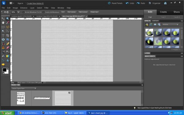
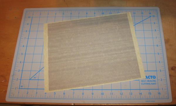
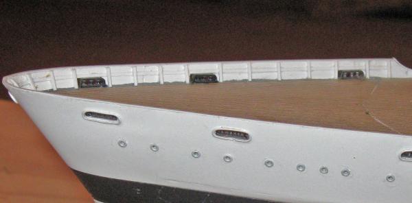
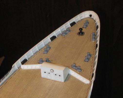
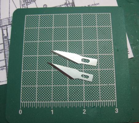
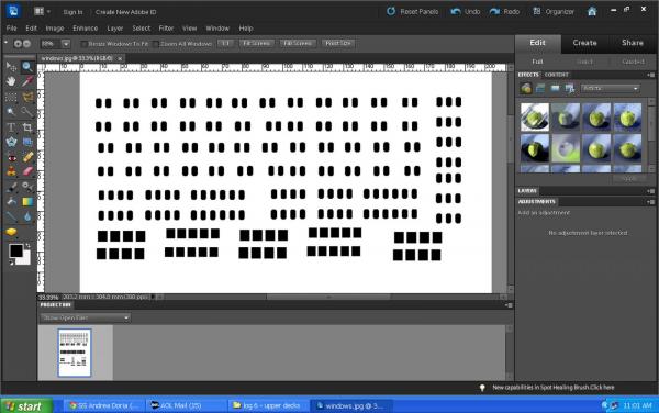
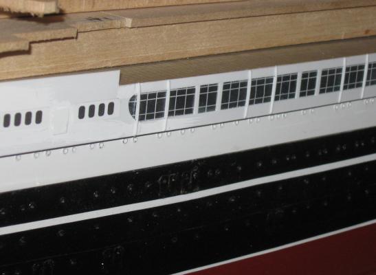
Build Log 6 – basic construction of the promenade deck Thanks again to all for all the likes and comments. I will try to continue to be entertaining as well as informative. Work continued on the bow area next. After a final sanding the perimeter of the bow was painted grey to represent the gutter that I see on almost all working decks. The fairlead fittings were cleaned up, painted and installed, then the deck was laid. My decks are paper printed with the plank seams. Acid-free heavy stock from the art supply store, but still just paper. Some prefer wood sheets or scribed veneer, but paper is really just very thin wood and I find it easy to work with. Paper also gives me the ability to do some tricks that I can’t do any other way without a lot more effort. Trust me, I’ve tried. I start with a drawing in my computer. Actually, I start with one horizontal line. This can be done with a drawing function in your favorite graphics program, or even in typing mode with a continuous underline, like we used to do with typewriters. This is then copied multiple times until the entire page is full of closely spaced parallel lines. I am working in Photoshop Elements, but Corel Draw or other similar program can do it. I believe that even a recent version of Microsoft Word can be set up to do it. Once the lines are drawn the image is printed. It usually takes a few tries to get the right enlargement or reduction of the image and to get the spacing to print out properly. In the scale of 1:192 that I am working in I use a spacing of 1mm, or 0.040”, which scales up to just under 8”. This is a realistic width for a deck plank and seems to be about as small as they can get and still have the human eye distinguish them as separate planks. When I tried a closer spacing the deck just seemed to blur and the distinction was lost. All of these were test printed on plain typing paper on an Epson 410 home printer in basic mode. When everything was right the printer was set to its finest quality and about a dozen 8” x 10” sheets were run off. After letting the ink dry overnight the deck side of the sheet was given several coats of a spray matte finish to seal the ink and prevent smudging. At the bow the open deck length was longer than the 10 inches of the deck sheets, so I had to use two pieces of my decking material. The joint between the two was located where it will be hidden under the breakwater, as can be seen in the first photo. The pieces were cut a little overlarge and a perimeter 1/8” wide in from the bulwarks was marked with a compass. The deck pieces were cut to that line and installed on the wooden subdeck. I used to install the decking by painting on a coat of wallpaper-type water based glue, but I found that it had a tendency to distort the paper shape. More importantly, I could never completely eliminate bubbles, even with wetting the paper and letting it rest before installation. Now I use a solvent based spray glue which does not distort the paper shape, adheres quickly, and is easier to apply. Initial positioning has to be more careful, since it adheres so quickly, but once it is burnished down with a pad of paper towelling it stays down. With the deck in place the bulwark details were added. Bulwark stringers and stanchions were cut from 0.030” square plastic rod and installed. Unless otherwise mentioned, all plastic to plastic joins are done with medium cyano. A caprail of 0.015” x 0.030” strip was applied to the top edge to finish the look and hide the ends of the stanchions. At the extreme bow it was curved by dipping the appropriate section into simmering water for a second or two, then bending and stretching it until it took the curve. On the forward deck seven bollards and one small capstan were installed as indicated on the plans. Hawse holes, anchor brakes and winches and other details will be built and added later. Along the perimeter of the deck each side has a section of 5-bar railing with a wooden caprail at the top. This is photoetched by Gold Medal Models and will be discussed in further detail later. To make sure that I was on the right course, all of the deck houses and decks were cut out according to the plans. The houses are ½” thick and the deck pieces are 3/32”, making each pair 9 ½ feet tall in scale, matching the plans. They were test fit repeatedly to judge relationships and to plan out where and how to make the plastic sheathing to cover them. After living with them for a while I felt that the bow deck fittings all stood out more than I wanted when they were painted black. I decided to have them match the perimeter color, so grey was mixed and they were repainted in place. The breakwater was cut and assembled from strips of styrene and tiny triangular supports. The deck house is basswood sheathed in 0.020” plastic. The front and sides were done first and sanded flush with the basswood, then the curved side/roof was wrapped over the top, trimmed and sanded. The doors are photoetched brass from Bluejacket. The clock is a slice of brass tube filled with a wooden dowel. The face was hand painted. Then I gave each fitting, and the entire bow deck, a margin plank. This is the technique that I can do with paper deck material that I can’t easily do otherwise. I simply cut a strip from a decking sheet with a new, sharp blade. I got some that are specifically made for the art market to cut paper. They are thinner than regular X-acto blades which makes them too weak to work with wood, but they have an angled end that gives the tip some added support for precise paper cuts. Although each fitting looks like it is completely surrounded by a margin plank, this is true only for the angled bollards and capstan. The ones that are square to the planking only have margin plank pieces at their ends. The eye perceives the side pieces even though they are not there. From the reverse angle I could see that some of the bollards needed touching up with grey, as did the capstan, and that was done. I find that taking lots of photos and examining them carefully really improves my work. You can see the almost completed forward end of the promenade deck. It incorporates several techniques which were used throughout the rest of the build. These include the plastic sheathing of the basswood substructure, the brass handrails, and the windows. I will cover the windows now and the others in later segments. Most of the cabin windows are custom decals that were created in my computer then printed onto white decal film. Photoshop gives me the ability to make up squares, rectangles and lozenges filled with black color. The size can be easily adjusted to any dimension. Once I make up one that I like it is easy to duplicate it and line it up in pairs, triples, or any combination or number. I examined the photographs of the ship and the plans, making a list of the window units that I would need for the first several decks. These were then created and laid out in the computer before being printed out onto water-slide decal film. Like the decking, the film was left to dry overnight and sprayed with matte finish. The window units were cut out carefully, dipped in water, and slid off the backing into place. Once in place they were further secured with a top coat of clear finish. You will see them in many of the photographs as the build continues. The most eye-catching windows, however, are the tall ones that run all along the promenade deck. As the photos show, they set up in a pattern of three blocks of nine panes then a single set of six panes. The smaller sets have wider frames which cover the structural supports for the lifeboat davits immediately above. I modeled this by laying out the panes in the computer and printing them out in segments that matched the repeating pattern. The black panes were printed onto white paper then affixed to the promenade deck structure. Plastic sheathing was added above and below the windows and the wide frames were pieced in using styrene strips of the appropriate width. The narrow frames were laid in, and some vertical supports were added on top. These supports do not show up on the plans, but are clearly evident in the photos of the ship. At the stern the upper deck ends in a semi-enclosed walkway before opening up to become the fantail deck. Stanchions along the perimeter of the working deck support it. The salon deckhouse has doors, windows and handrails and is topped by the boat deck which contains the aft bridge wings and the pool for the third class passengers. The model’s stanchions are brass rods fed through holes in the upper deck and into matching ones in the working deck below. They were painted white before the decking was added to the fantail. To made construction as easy as possible the decking was laid down overlarge, then trimmed to the perimeter before the edge was sheathed. The sheathing stands a little proud of the deck surface and creates a lip which will guide the photoetched railings later in the build. Here, a little later in the build, you can see how these same techniques have been used to build up and detail each successive deck. The holes for the third and second class pools have been cut into the decks, as have the companionways which will later get photoetched stairways. The only new technique here is for the doors. Whether singly or in pairs they are printed onto art paper and glued in place. I am slightly unhappy with them and think that the next set will be a bit more detailed. So here is where model was at the time. The decks and major structures for the upper and promenade decks were done. The rest of the decks were roughed out and stacked in place without being secured, ready for sheathing, decking, windows, doors and handrails. The smaller and finer details will be added to this growing structure. Please feel free to ask for enlarged discussions if I have left something out or been too brief with my explanations. Be well Dan
- 108 replies
-
- 13
-
-
- andrea doria
- ocean liner
- (and 1 more)
-
Hi Cristiano - Thanks so much for the links. When the time comes I will order the plans from the Society. I did locate the photo gallery that you pointed me to and it will be a great help in getting the details right. Thanks also for the compliments. Be well Dan
- 108 replies
-
- 5
-
-
- andrea doria
- ocean liner
- (and 1 more)
-
Grant - Really beautiful work. Clean, precise, accurate. I enjoyed your inventive solutions to the challenges of making such a complex part. Now I just have to get over my 'machine envy.' at your fabulous tools. I would run out and get a set, but by the time I figured them all out I would probably be past my last sale date. Either that, or everything will be done by 3-D printing or personal robots. :-)) Looking forward to your cannons. Dan
- 456 replies
-
- 4
-
-
- finished
- bomb ketch
- (and 2 more)
-
Zebman - Thanks for the information. It is too late to do anything about the hull shape of the AD, but I am slated to build the SS Michelangelo in the future and would really appreciate anything you can spare or copy of her plans and drawings. All costs reimbursed, of course. Dan
- 108 replies
-
- 3
-
-
- andrea doria
- ocean liner
- (and 1 more)
-
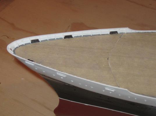
Build Log 5 – starting the upper decks Now that the summer is mostly over I can leave the grandchildren behind for a while, lovely as they all are. Back to the building board and the keyboard. Thanks for the likes and comments. Although I am reporting on aspects of the build that have been completed, I am still building the ship, and your responses always give me a boost of energy. The next segment of the build was finishing some of the last details on the lower hull and starting the first of the upper decks. When the last episode ended, the lower hull was almost complete, and this was the photo I showed. However, this skips a few steps that I did not take photos of. Before the lower hull could be painted and the white sheer stripe applied, I had to make and install the bulwark around the aft working deck. This was the first piece of plastic installed on the model. A shallow rabbit was carved into the wood of the hull all around the stern lift 1/8” tall and extending 1/8” into the uppermost lift on each side. A strip of 0.020” plastic was held in place and the line of the working deck was drawn its inside face. Using this reference the upper edge of the bulwark was marked out, including the two swooping decorative curves at the ends that rise to the next deck level. The piece was installed with medium cyano then the seams were puttied and sanded flush with the surrounding wood. At the six spots indicated on the plans the bulwark was pierced for hawse holes. These were drilled and shaped into elongated “D” shapes with files and scalpels. They each got a perimeter support of wire, but this detail shows up better in later photos. When this was all set the hull was primed, painted and the stripes applied. The layout of the deck fittings for the aft mooring lines was taken from the plans. Behind each hawse hole there is a fairlead with three rollers. Nearby each is a large twin bollard to belay the lines. To work the lines there are three powered capstans. The fittings were adapted from commercial Brittania castings that closely matched the appearance of the ones on the plans and in the photographs of the ship. They were each cleaned up with grinders, files and sandpaper to remove mold lines, flash, and excess metal, then primed, painted and installed with pH neutral white glue. The decking that they sit on is acid-free paper printed on my computer, but this technique, and several others, will be discussed in depth when it is more central to the build. Here, as you can see, not much of the working deck is visible once the next deck is installed so I took the opportunity to do a little experimentation with the salon walls. Some of this did not work out completely happily, but forgive me if I do not reveal all of my mistakes. To finish the lower hull all that remained were the bilge keels, the rudder and propellers. The keels are simple straight stringers with a narrow triangular profile that are set along the lower hull chine to aid stability at sea. They come up in some of the later shots, but I did not take any specific photos as I made them. The shape of the rudder was taken from the plans. It had a central plate with reinforcements on both sides at the hinge edge. This was built up from a piece of 1/16” thick hardwood with reinforcements of 0.030” styrene. The rudder post was notched for the hinges and filed to final shape. A hole was drilled up through the rudder and post and a brass rod inserted. This allowed the rudder to turn about 20 degrees port and starboard. However, the basswood of the hull turned out to be too weak to support this action and cracked. It was repaired and the rudder fixed in place. As for the propellers, I tried to source a pair of 4-bladed props in solid brass, but they all were too large or too small. A pair the right size were obtained, but in cast Brittania. They were cleaned up, smoothed and polished, then painted with metallic gold enamel, which gives them an appearance close to brass. I know that the real ones were probably a dark bronze color, but this seems to be the style for ocean liner models. In the photo you can see how the upper deck has been temporarily secured to the lower hull with a screw. There are two others along the centerline that hold the upper deck exactly in place on the hull so the upper decks can be removed to be worked on and then replaced exactly. This was done a number of times in the process of getting the upper deck to match exactly the outline of the upper hull, but just a fraction smaller to allow for the plastic sheathing to come. When I was happy with the fit, the upper deck was screwed down and an overlarge piece of 0.030” plastic was held against it around the bow to begin the bulwarks. Here the lower edge of the piece has been fitted to the lower hull but the upper edge is still overlarge. A second piece of plastic was fitted to the first and led aft along the side of the upper deck. It extended back to where the promenade deck overhangs the upper deck. Again the top edges were left a little large. This was done both port and starboard. With them secured in place the top edge all along could be marked up from the deck, then shaped with sanding blocks. The scallops were cut out in place so I could get a straight and consistent lip for the photoetched railings to come. A total of nine hawse holes were opened in the bulwarks around the bow, including a small circular one at the very point. They all got wire reinforcements like the stern hawse holes. This was done by bending 0.020” soft iron wire to the “D” shape of the holes, but sized to fit on its outside perimeter. They were secured with cyano initially, but then each was painted with epoxy to smooth the edges and fill any gaps. Here is the bow from directly ahead in a shot a bit later in the construction process after the first coat of primer. The sheathing continued aft with pieces under the overhang of the promenade deck. This extended to the beginning of the salon with some left to carve for the decorative curves later on. All of the portholes were located, drilled and filled with the small eyelets. Then the upper deck was unscrewed and removed from the lower hull so it could get a coat of spray white primer. Any open joints or defects were filled and sanded, then the sheathing got a final coat of gloss white. It’s starting to really take on the look of the ship, if only in a partial photograph. More soon. Dan


- 108 replies
-
- 18
-
-
- andrea doria
- ocean liner
- (and 1 more)
-
HMS Victory by willz
shipmodel replied to willz's topic in - Build logs for subjects built 1751 - 1800
William - Excellent marquetry work with the contrasting woods. Dan -
Nice work, Mark. You are really getting the hang of planking and spiling. I completely agree with Druxey - go slow when correcting plank runs. Take at least three strakes to fill in a dip or level a hump. No one will be able to see the incremental difference, which they could if you try to fix a problem all at once. Congrats, again. Dan
-
Grant - Excellent upgrades! I also can't see the joints. I'm glad that you are happier with your project, and for having a small part in it. Nice work. Dan
- 456 replies
-
- 5
-
-
- finished
- bomb ketch
- (and 2 more)
-
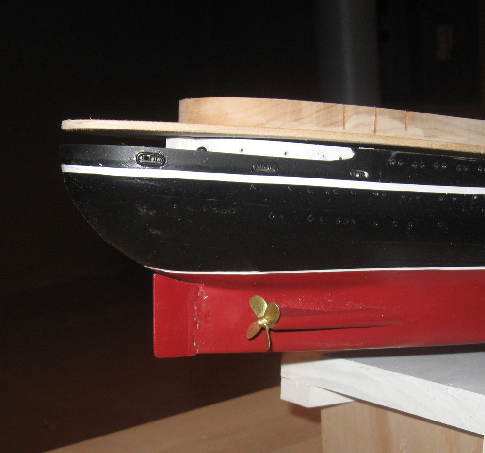
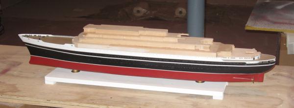
Hi Nils - Thanks, but I'm not really that fast. I should have mentioned that I have been working at this while doing the QAR over the last year. My customer was entitled to a measure of progress, so whenever I could find or make some openings in the schedule I worked on the Doria. Now that the QAR is done I am spending all my time on this and really getting into the details. Here is what she looks like today. For the portholes I just drilled deeper than the shafts of the eyelets. I didn't see a need for anything more. It was suggested by a friend that I fill each porthole with white glue to simulate glass, and I may yet do so. Even without that I think that they look pretty good and have gotten better as the black paint over time has given them dark brass highlights. Dan

- 108 replies
-
- 14
-
-
- andrea doria
- ocean liner
- (and 1 more)
-
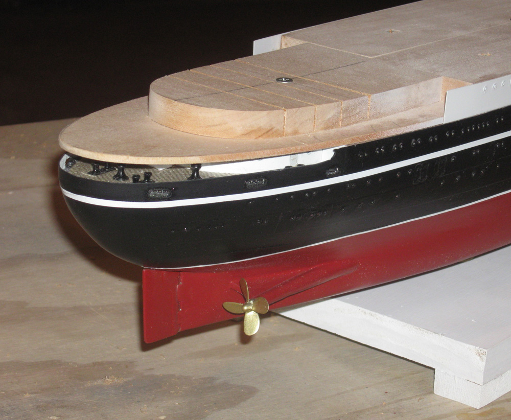
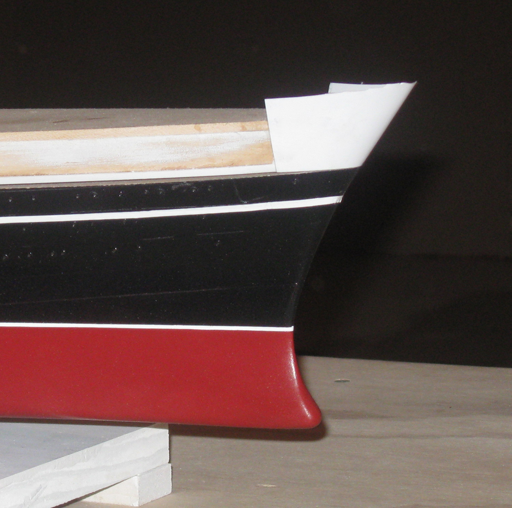
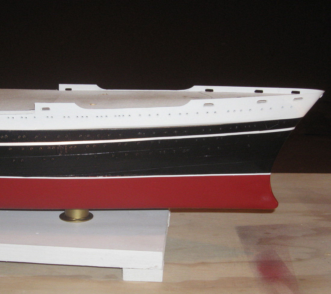
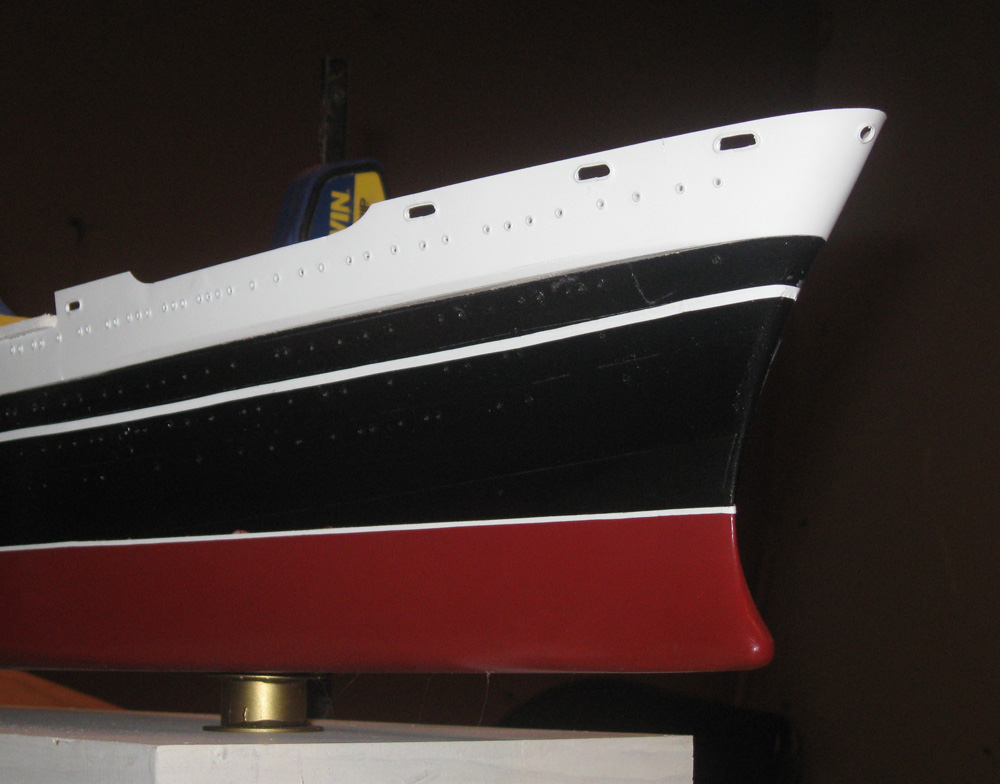
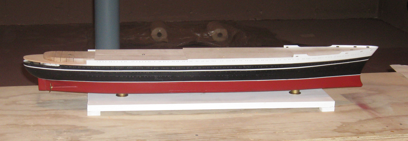
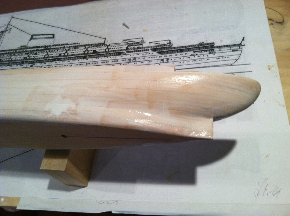
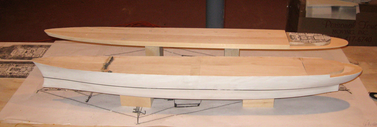
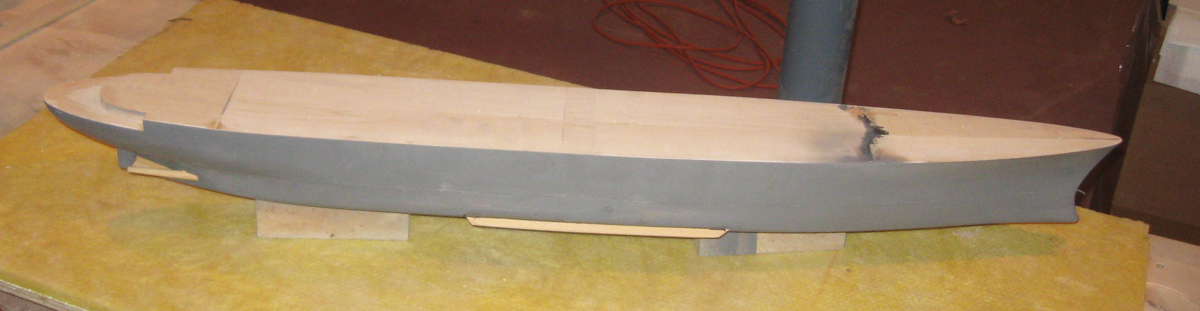
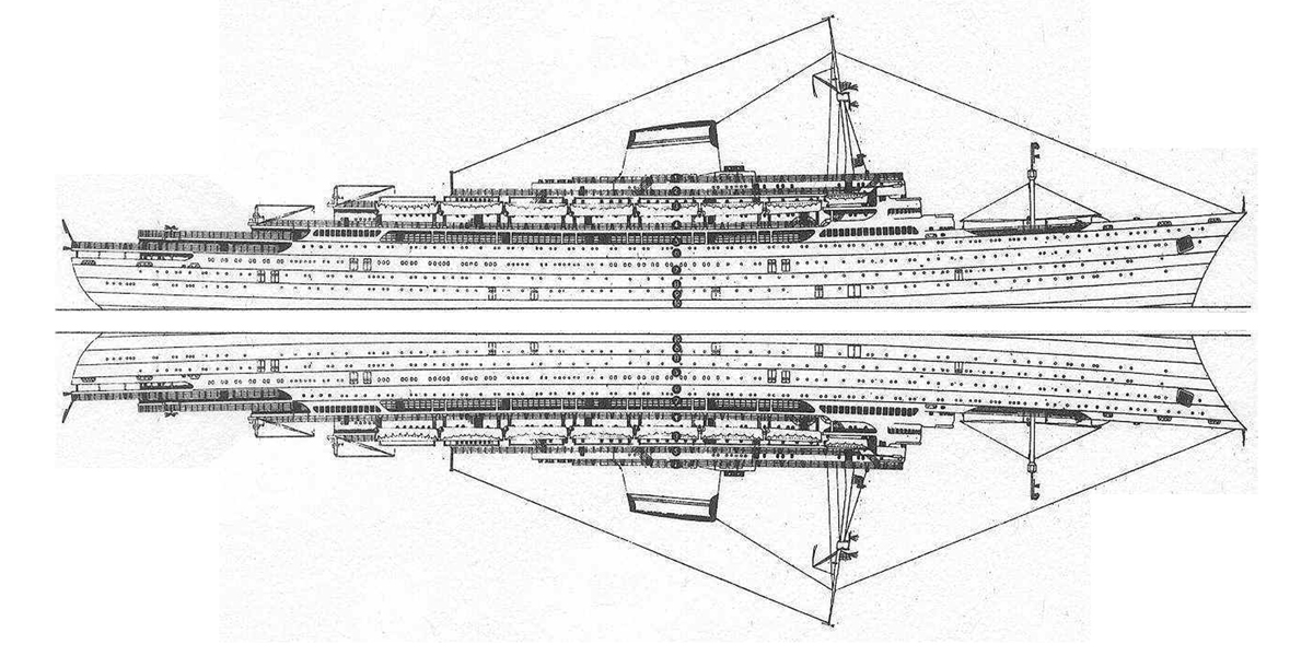
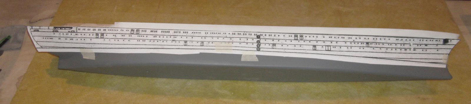
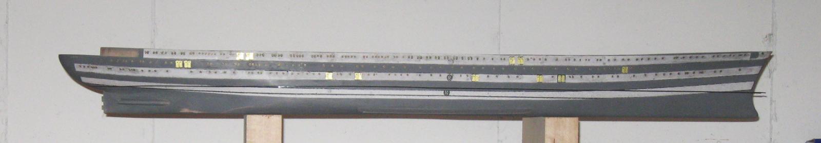
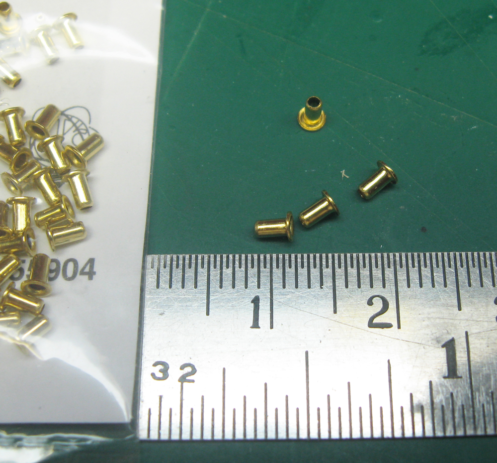
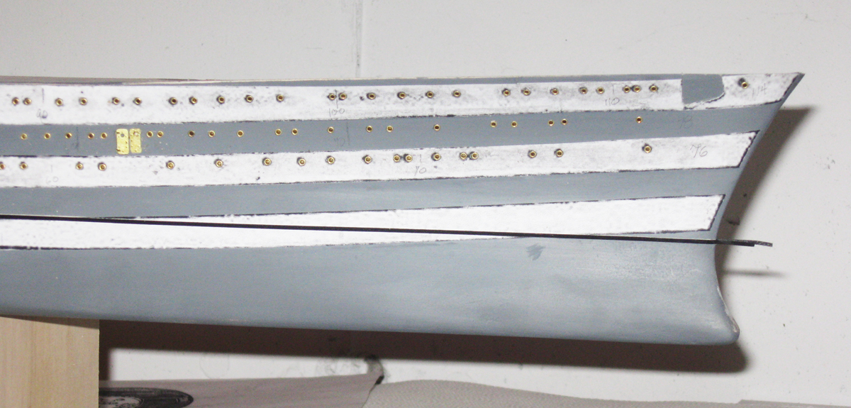
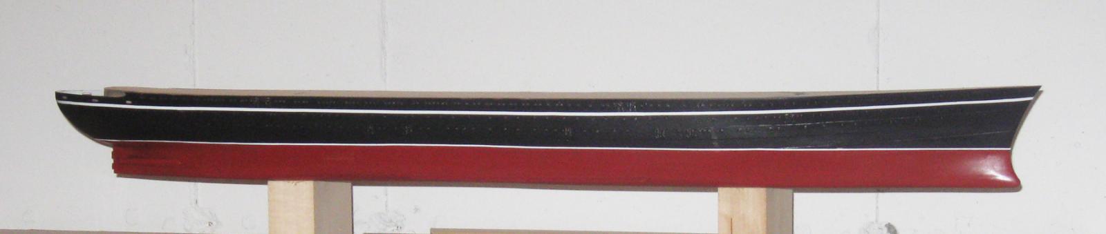
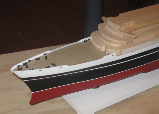
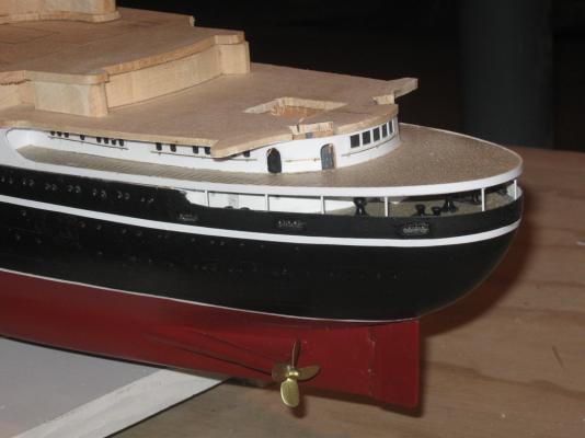
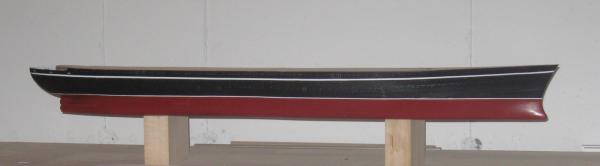
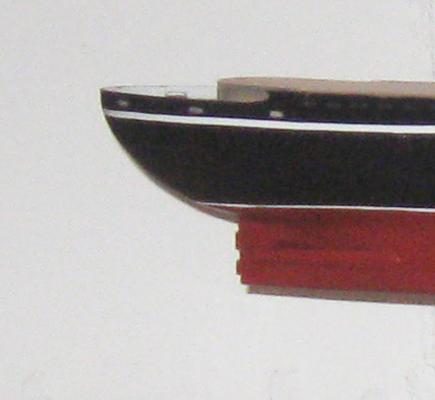
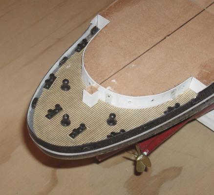
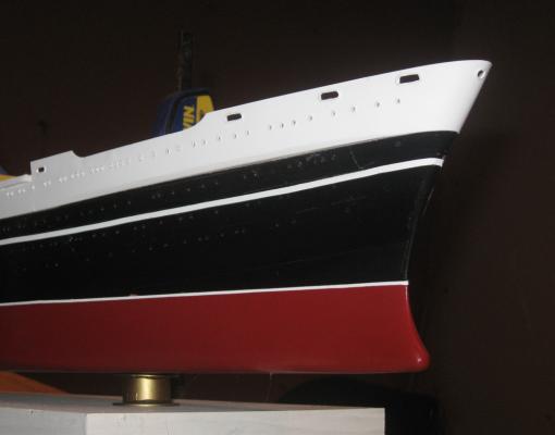
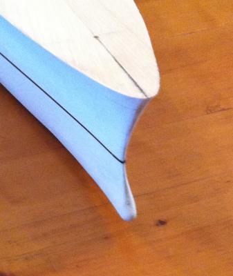
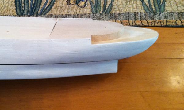
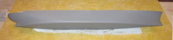
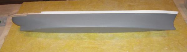
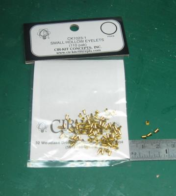
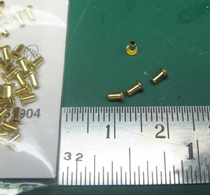
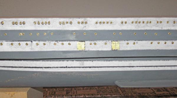
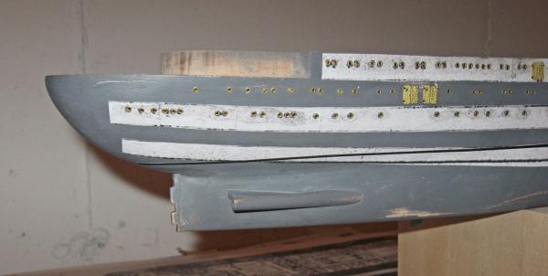
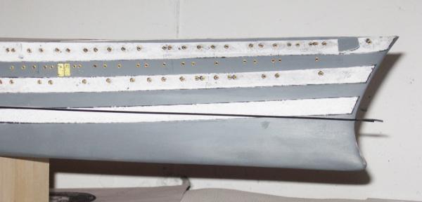
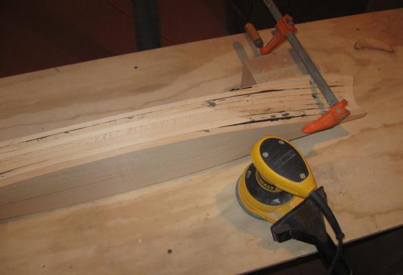
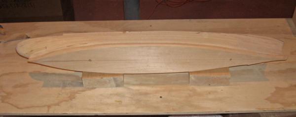
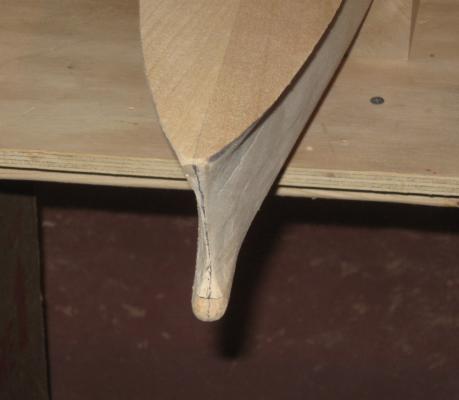
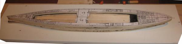
Build log 4 – finishing the lower hull Thanks to all for the likes and comments. I was only five when the accident happened and I did not realize how memorable it was to so many of our community. I trust that I will do her justice. Here is where the last segment left the model – all of the lifts for the lower hull have been laid up, then shaped until the hull was smooth and close to the final dimensions and curves. From there it was simply a process of continued shaping and making educated estimates for how the curves would fair into each other. I had the longitudinal cross section plan so I could make templates for the bow and stern, and I did. But these were of limited usefulness since I did not have any station lines to guide the shaping of the rest of the hull. Nonetheless, I used the curves from the deck plans, the photographs I could locate, and my experience with other liner hulls to get a pretty close match. Sanding rods of various diameters and grits did the final shaping. Once I was happy with the result, I sealed the surface with Minwax Wood Hardener. This product goes on as a thin clear liquid, but dries to a very hard solid. It is used to stabilize soft and rotted wood so new repairs will have something to grab onto. In modeling it makes a wood surface that will not move and is highly resistant to dings and dents. It is also a bear to shape, so I always get the part as close to final tolerances as possible before painting it on. It raises the grain a little, so once it was dry I gave the hull another sanding. But the hardener does not fill grain or any voids between lifts. To do this I painted the model with a slurry of thinned plaster of paris. Here it is on the stern while it was drying. While I could still see the black glue lines between the lift layers I took the opportunity to lay on a 1/16” vinyl tape at the waterline, just above the top of the third lift. When the plaster was dry it was sanded with several finer and finer grits until the surface was completely smooth. At the bow the sharp entry is clearly seen, although I have left it a little thick to allow for final adjustments. At the stern I have laid on a separate piece which housed the salon and stairways on the Foyer (Vestibule) deck. This has been faired to the outer hull, leaving open the area that will become the aft working deck for handling the stern lines. From the side you can see how the wedge shaped lift is tilting up the deck house along the sheer. The tape for the waterline runs around the counter just above where the rudder will hang, as the plans show. With the lower hull almost fully shaped I roughed out the next layer, the Upper Deck. It was started on a continuous sheet of 1/8” basswood that fit on the lower hull and took the curve of the sheer quite well. Then there was a ½” layer that extended almost all the way back along the length of the hull. The thicker wood took some persuading to accept the sheer curve. It was wetted down with water on both sides before being clamped to the work surface amidships. Wedges were used to lift the bow and stern ends further than the sheer curve required. This was left to dry for several days, and even had to be repeated before it held the required curve after allowing for springback in the wood. You can see how it lies on the lower hull snugly without clamps or other force. The aft deck house for the Upper Deck salon has been added as well. The mating edges were shaped to each other, with a small allowance in the upper layer for the plastic sheathing to come. I also did the final shaping of the lower bow which would fair into the upper overhanging bulwarks. The upper section was set aside and the lower hull was primed with Krylon spray sandable gray primer. This exposed some additional roughness, which was sanded smooth before priming again. Then the hull was sanded and primed three more times. It can't be seen, but the tape is still there, marking the waterline for later. The fit of the Upper Deck was tested again, this time with it painted white for contrast. It is starting to look like a hull at this point. It was by looking at this photo that I realized I had made a pretty big mistake. Without any guide from a section plan I had left the curve from the flat bottom of the ship to the vertical side (the chine) too sharp. Although it was hardened, plastered, and primed I got out the power sander and rounded it till it matched the curve in the launching photo shown in build log segment 1. Sanding, hardening, plastering, and priming got those areas back matching the rest of the hull. Now I could fashion and attach short bilge keels amidships on either side, as well as tapered propeller shaft housings secured by solid webs to the hull just forward of the rudder post. The surface of the lower hull is highly complicated, although the elements are quite subtle. The major ones include the portholes, exterior doors, and the well for the anchor. But the first one to be addressed was the most subtle, the plating strakes. These do not show up at all in photographs of the ship after it was painted, but close examination of a number of construction photos convinced me that it was built with several strakes of in-and-out plates. These also looked to have been welded, since no rivet heads were evident. These strakes followed the lines of the decks, which meant that the portholes followed the same lines. To get them located I had the exterior deck plan to work with. I knew that I would have to have separate plans for each side of the ship, so in Photoshop I mirrored the plan and flipped it vertically to make one plan that could be printed out. This was printed and trimmed before being tested on the hull. It turned out that the curve of the hull meant that the plan had to be slightly lengthened to match the photos. When I had it sized correctly I had the shop print out another one onto acid-free art paper which was a bit thicker than their usual stock. This was taped to the hull and the location of each of more than 700 portholes was set by piercing through the plan and into the hull with a sharp awl. Then the plan was sliced up and the three ‘out’ strakes were glued to the hull with pH neutral PVA glue. When the strakes were dry, holes for the portholes were drilled with a battery-powered Dremel and filled with tiny brass eyelets. The exterior doors were photoetched brass items from Gold Medal Models and Bluejacket. The porthole eyelets are the smallest I have been able to find. They are used as electrical connectors for dollhouse lighting systems, but work perfectly here. They come in packs of 110 for not a lot of money, so I buy 1100 at a time. They measure 0.097” across the outer flange, or 18.6 inches in full scale. The opening tapers a bit, but visually appears to be about 0.056”, or just under 11 inches. This is more than close enough for me. Here in the midships view you can see how the portholes line up along the plating strakes. After drilling out all of the holes I dabbed glue into each then inserted an eyelet using the tip of a modified wooden skewer. As you might imagine, this is a tedious and repetitive activity, like tying ratlines, but good music and occasional breaks for a sip of good libation goes a long way toward making it agreeable. I have to say that the final product is worth the effort. At the stern here are the strakes, as well as the propeller shaft and the hinges for the rudder which have been cut into the rudder post. The spot where the primer has been sanded off reflects the ongoing process of examination, evaluation, and adjustment that will go on until the model finally leaves my hands. At the bow the plating rises with the sheer. In the upper strake the well for the anchor has been cut out and the hull will be carved out in a shallow box as seen in the photos. This box extends up into the white upper works, but that is for later. When everything was dry I gave the hull a final coat of primer and a long, thorough examination. After a few minor adjustments and an overall fine sanding, the lower hull was painted with Krylon enamel in a medium dark “Farm Equipment Red”. The waterline tape was removed and the red was masked off, then the upper portion was painted gloss Black. White striping tapes were used to lay on the waterline and the upper sheer line decoration. I use the tapes because my hand is completely inadequate to paint, or even mask, such long lines with any consistency. The waterline is 1/16” wide, while the sheer line is 1/8”. I used Detail Master and Super Stripe tapes which are called pin-striping tapes for automobiles and their models. Using the tapes also allowed me to easily reposition the lines as needed, especially the sheer line which did not have the guide that the waterline had. A few coats of clear gloss were laid on to protect the tapes and color coats and to even out any differences in sheen. The lower hull was now ready for the rudder and a few additional details before being mated to the upper works. I will get to that in the next segment. Be well Dan


- 108 replies
-
- 17
-
-
- andrea doria
- ocean liner
- (and 1 more)
-
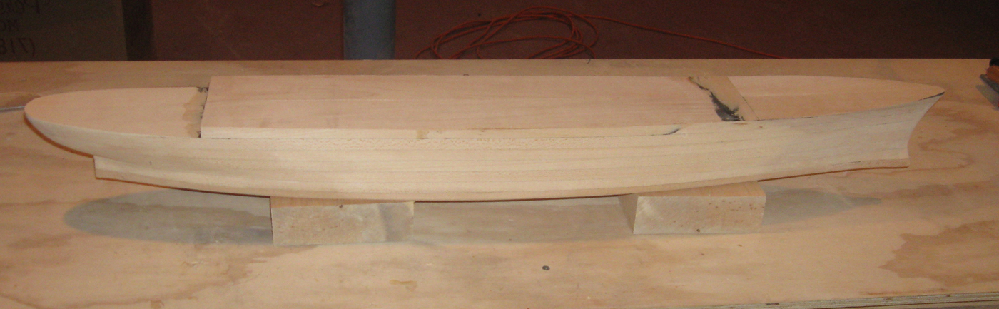
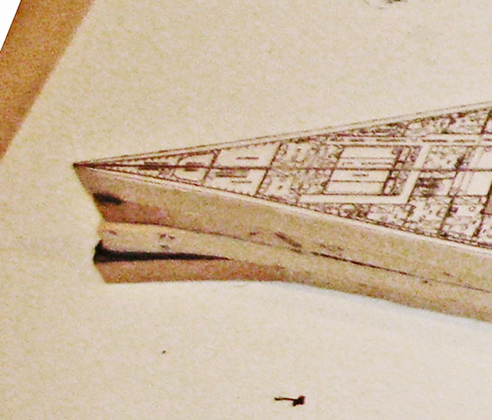
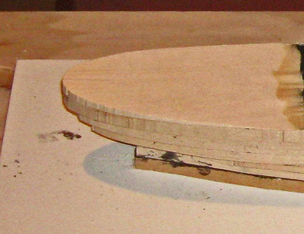
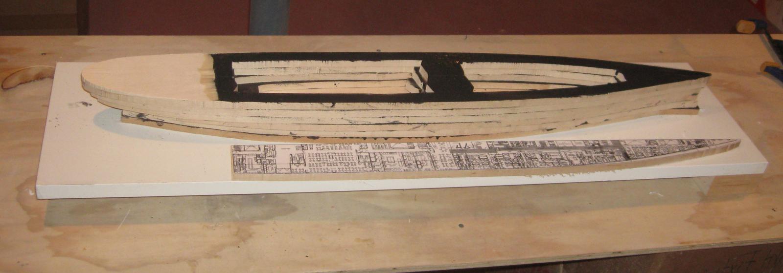
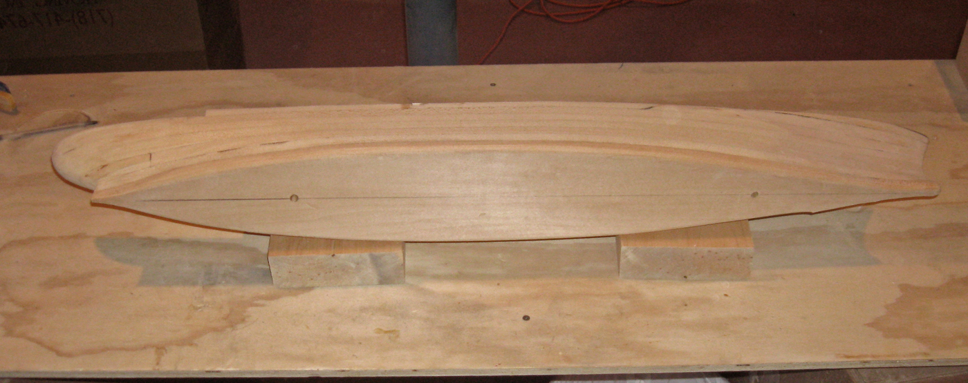
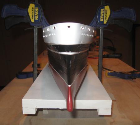
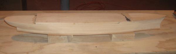
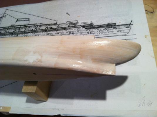
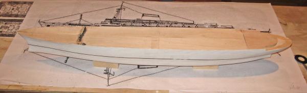
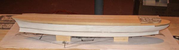
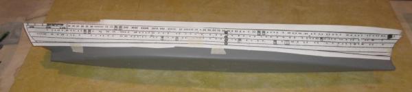
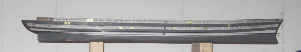
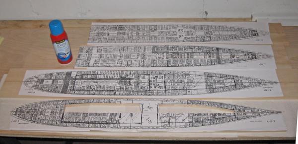
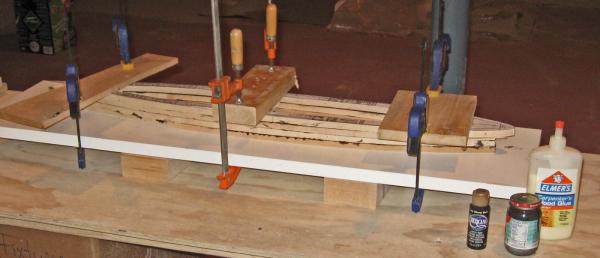
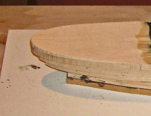
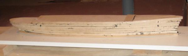
Build Log 3 – laying up the hull With the lifts set and adjusted in the computer I took a disc with the files to the blueprint shop and had them print out two sets – one to use and the other as backup for the inevitable mistakes. They were done on the least expensive paper in the shop, so getting two sets was easily affordable. A word of caution for those who use this sort of service - although their printouts are quite accurate, their usual customer does not build directly from the plans, but from the listed dimensions. Since I would be cutting directly from the drawings, I had them check. The first page was about 2% off. This is not much in a printed document, but in a 43 inch model this is about an inch. They corrected the problem and the rest were spot on. I had already determined that the maximum breadth of the model would be just over 5 ½ inches (90.25 feet at 1/192 = 5.64 inches), so I ordered a number of planks of seasoned and dried basswood ½” x 6” x 48” from National Balsa, a reliable supplier in Massachusetts that I have used before. I also ordered a number of ½” planks only 3 inches wide, together with 3/32” sheets for the decks. These were all left in the shop for a week to acclimatize. The 3” planks were something of an experiment. On previous liner models I had created hollows in the lifts to lighten the model and give the wood some space to move rather than cracking the exterior of the hull. But I was not happy with the process. I would cut out the center of the middle lifts on my tabletop band saw, but its small throat meant that I was frequently turning and backing the blade. Also, there was always a small kerf in one side of each lift that had to be filled and sanded and which created a weak spot. This time I tried using two half width lifts that would make up one already split along the centerline. I would have access to the center of the lift without going through the outside. Here you can see the process. Each lift plan was cut from the sheet and sprayed with Scotch spray mount, which allows some repositioning during adhesion, and removes cleanly with mineral spirits. For the solid lifts a centerline was drawn on the wood and the plan pasted down along it. For the split lifts the two 3” planks were held together with clamps while the plan was laid down along the line where they abutted each other. While still clamped the plan was split along the line with a sharp hobby knife. For each lift the material to be removed was drawn on the plan and then cut out on the band saw. A central bar was left solid for rigidity and to make sure the hull did not shift. That may have been unnecessary, but I felt more comfortable with it there. In the photo you can see that Lift 5, at the bottom, has been split and the voids cut out of the port side. I started with two full width lifts to make a solid base for the hull. A pair of T-nuts were fitted into the lowest lift in holes drilled through from the outside in to minimize any chipping around the visible hole. A matching pair of holes was drilled in the second lift so the mounting bolts could come through into the hull and be as long as needed. This second lift trapped the nuts so they could not shift. Each lift was painted with glue and positioned on the one below. When the glue set up enough to prevent movement the top lift was clamped down with three cauls and left to dry. You can see that I have used black glue. It is simply made by adding a few drops of acrylic craft paint to wood glue. Doing this gave me a set of true horizontal layout lines that would never disappear no matter how much material had to be removed in the shaping process. These lines could be viewed from any angle to get the curves accurate and symmetrical. Also, in the past I have had some trouble laying out and keeping a level waterline and I thought I could rely on the lift junctions as a guide. Here are the first four lifts cut out and glued up. The angled sides of the center bar were necessary to accommodate the shallow throat of the band saw, but these would be hidden deep inside the hull. Here is the bow with the extra material added to the bottom two lifts. And the stern with the third lift split into the two half layers to match the plans. After the sixth flat lift had been glued up I had to make the first of the wedge shaped lifts, the half height one (7A) at the stern. It was cut to the shape of the aft end of the Foyer deck and the length as taken from the lift plan. Then I tapered it down and forward with a block plane until the front edge was feathered to next to nothing. It was glued down and would later be sanded to a gentle curve to match the sheer. With 7A installed I could add the forward section of lift 7. Here is the hull painted with glue and ready for it. This lift was made solid since it would be the last (almost) full lift below the color separation line. The final lift for the lower hull was the wedge lift at the bow. This was roughed out and installed and the rough hull block was complete. Now it was just a process of shaping the exterior to match the plans. The boxy midships areas could be brought down with a palm sander. To reduce the dust generated I attached one of the small hose ends of the shop vac to the dust port on the sander. Whenever I sanded I had the vacuum sucking up as much dust as possible. There was still some, so I wore a dust mask. Ear protectors too. Running both machines at once was quite loud. Using the sander, a sanding drum in the Dremel, wood rasps, and whatever else would remove wood, the hull was brought down to a rough but close approximation of the hull shape. In this view from below the two mounting holes can be clearly seen. At the stern the rudder post and counter are approaching their final shapes. The working area of the Foyer deck has been sanded to the gentle curve of the sheer. At the bow the split line of the half lifts gave me an indelible line to shape the knife edge at the waterline and the bulb below. So here is where this segment ends, with the lower hull laid up and approaching its final shape. Be well Dan


- 108 replies
-
- 19
-
-
- andrea doria
- ocean liner
- (and 1 more)
-
Mark - Those PDFs were excellent and the decorations will make this an outstanding model. Dan
-
John - You are obviously more restrained than I am. My usual exclamation is "Merde!!" Dan