HOLIDAY DONATION DRIVE - SUPPORT MSW - DO YOUR PART TO KEEP THIS GREAT FORUM GOING! (89 donations so far out of 49,000 members - C'mon guys!)
×


shipmodel
-
Posts
941 -
Joined
-
Last visited
Content Type
Profiles
Forums
Gallery
Events
Everything posted by shipmodel
-
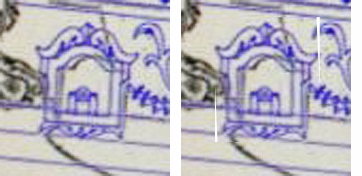
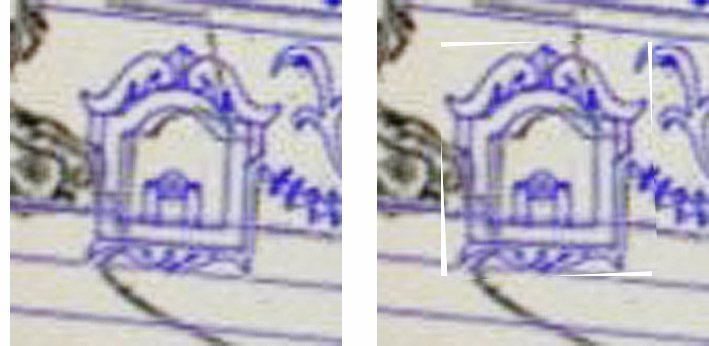
 Hi Marc - I think the fact that several of us have noticed the tipped gunports on the Heller casting means that they are eye-catching elements and should be adjusted if it can be done without too much work. Looking at your drawing carefully it seems that the tipping is more apparent than real. Here is how I would go about changing the model and the drawings: For the model, not much work is needed. Even the sides of the aftmost gunport need to be shifted only about 2 degrees. All of the others are closer to vertical and need less adjustment. The insides of the port can be modified with a needle file. It may be that only doing the verticals would be enough to change the look of the piece. Doing something physical on the model might make a nice change from all the drafting. As for the drawing, I do not know the program that you are using, but check to see if there is some 'rotate' or 'skew' function that you can apply to a selected portion of your drawing. The Photoshop Elements program that I use has several. Here I have simply taken a square outline of the gunport and rotated it to vertical. The second has the gunport skewed, which leaves the sill tipped. The program also lets me more carefully select just the gunport by using the 'lasso' function, but that is a much more time consuming process. If your program does not allow you to do this, I could do it for you if you send me a JPEG file of your entire hull. Dan
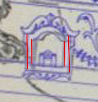
- 2,697 replies
-
- 2
-

-
- heller
- soleil royal
- (and 9 more)
-
Hi Marc, E.J. - I am highly enjoying your discussions about the interpretations of these artworks as research tools. I am learning a great deal from your thoughts and M. Saunier's as well. Thinking about the question of open or closed galleries, it occurred to me that perhaps there could have been removable shutters to protect against sun, wind and elements. Then when the 'photographs' were taken, sometimes they were on, and sometimes not. It makes sense from a practical point of view, but is that something that has ever come up in your readings? Dan
- 2,697 replies
-
- 2
-
-
- heller
- soleil royal
- (and 9 more)
-
Beautiful work, Chuck. A faithful honoring of the historical details and shipbuilding methods, without ever losing sight of the artistic whole. Such elegant solutions to so many construction challenges along the way. And such ingenious business sense to turn your efforts into your mini-kits so we can all benefit. Thanks for leading the journey. Dan
- 1,051 replies
-
- 8
-
-
- cheerful
- Syren Ship Model Company
- (and 1 more)
-
Hi Frank - What a lot of great work has been done since I looked in. Very precise and clean. This promises to be an excellent model. One small suggestion. For the ceiling planks it does not matter so much, but when you go to show treenails or bolts in the hull or deck planking, you should stagger the two for each plank diagonally left and right along the beam or frame. Putting them in a straight line puts the line of weakness from the holes and the line of strain from the bolts all along the same grain line in the wood. This would increase the danger of splitting along that line. I've never seen it done that way except in ships with wooden decks over a steel framework. Of course, if your excellent and thorough research and photos shows otherwise, I am fully prepared to be wrong. Be well Dan
-
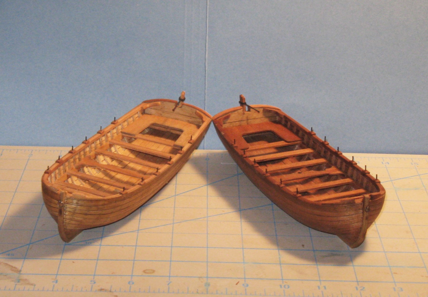
Hi Eddie - I am following along as well and looking forward to your progress. The two woods that you have chosen are pretty dark. You may not like the boat that color. You can always stain a wood darker, but not lighter. For comparison, here are two boats that I did, and the lighter one is always the more popular. They are in the same scale as your build, 1:36. The lighter one is stained basswood, the darker is cherry. Whatever you choose, best of success. Dan

-
Hi Doris - I found the drawing that I was thinking of. It turned out to be the Royal Katherine herself as drawn by VdV the Elder in 1673 and reproduced in Frank Fox's book "Great Ships - The Battlefleet of King Charles II". As he shows, the half gangway goes up only to the entry port, which is much closer to the forward gunport than I would have expected. This may have been forced on the builder by the forward location of the main channel, which would have been much more difficult to move. Please be assured that none of this nit-picking detracts in any way from the beautiful work that you are doing. Be well Dan
- 1,035 replies
-
- 14
-
-
- royal katherine
- ship of the line
- (and 1 more)
-
Hi Doris - Thanks for pointing me to the models. I think I see how it works. The steps only go up to the level of the entry port, which is offset aft. This is the officers' entry. For the rest, a rope ladder, probably with wooden steps, would have been lowered from the rail and over the closed gunport. In combat it would have been pulled up, of course. I saw this feature in some Van de Velde sketches, but thought that the incomplete ladder was just an artistic shortcut. I should never doubt the master. Dan
detail.jpg.043af16d361fa163643a5476b1997271.jpg)
- 1,035 replies
-
- 7
-
-
- royal katherine
- ship of the line
- (and 1 more)
-
Hi Doris - Beautiful work, as always. Your build logs have elevated my own work, even on such different subjects as the ocean liners that I have built. I have one small question - do you think that your entry port is too far aft? Is there enough room for the crew to secure the train and breeching tackle for the gun immediately aft of the port? How will the steps for the gangway run up to the top rail? I have seen the painting of the ship with this feature placed as you have it, but I can't figure out how it would work. Thanks Dan
- 1,035 replies
-
- 5
-
-
- royal katherine
- ship of the line
- (and 1 more)
-
Hi Marc - I see the same issues as M. Saunier. The detailed drawing that he provided should give you a lot of information. It certainly looks better than some of the other drawings of the head structures. Perhaps you can develop a drawing of the bow from above (plan view) which will give you a better feel for the relative positions and sizes of the catheads, headrails, and carvings. The two-dimensional drawings distort the look and placement of the catheads. The placement and size of the carvings as drawn may set the catheads so far forward that it would be impossible to work the anchors without damaging the headrails. Another question is about the number of gun decks at the bow. i do not recall seeing a plan or drawing of the bow which shows 4 decks of cannon as you have them. Rather, the Berain painting that you included seems to show only 3. How are you resolving this conflict? Lots to think about, but you are up to it, I know. Dan
- 2,697 replies
-
- 3
-
-
- heller
- soleil royal
- (and 9 more)
-
Hi Doris - Great to see you back in the shipyard. What you do with cardboard is truly spectacular. I will be following along with great interest. Be well Dan
- 1,035 replies
-
- 9
-
-
- royal katherine
- ship of the line
- (and 1 more)
-
Hi Marc - Love the way this is coming along. You are certainly doing everything you can to make her accurate, according to the information you have. I don't envy your huge task in making all of the decorations and carved work. The horse-headed catheads are particularly complicated, and I imagine that they will be difficult to work out how to add the decorations and still have a working anchor davit. One quick question - the surrounds for the third deck gunports, the ones with the antler/acanthus decorations, are slanted at the fore and aft ends of the line. They are the only gunports that are tipped this way. Is this how they are on the ship or is this an artifact of the drawing process? Looking forward to seeing her in person. Dan
- 2,697 replies
-
- 3
-
-
- heller
- soleil royal
- (and 9 more)
-
Hi Nils - Yes, it was the unavailability of cylindrical ones that small that clinched the decision. Dan
- 287 replies
-
- 4
-
-
- michelangelo
- ocean liner
- (and 1 more)
-
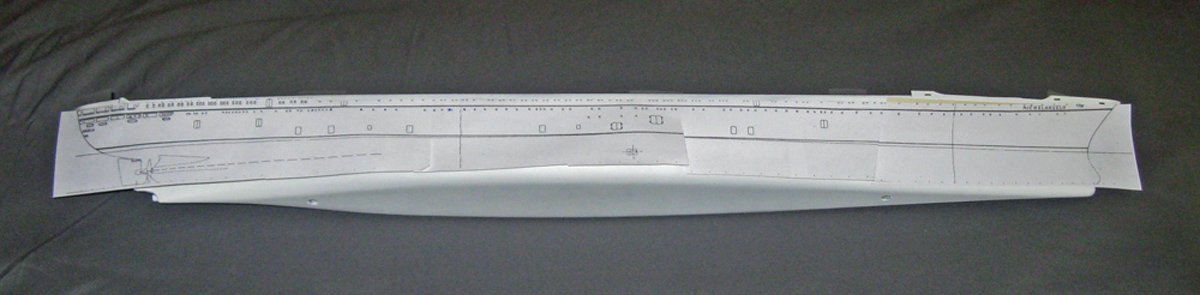
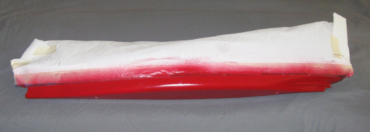
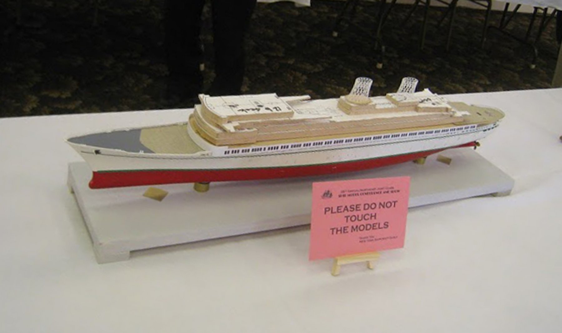
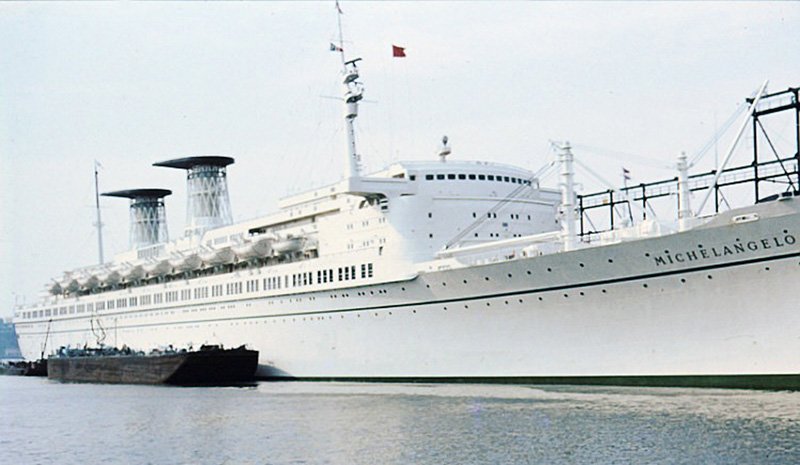
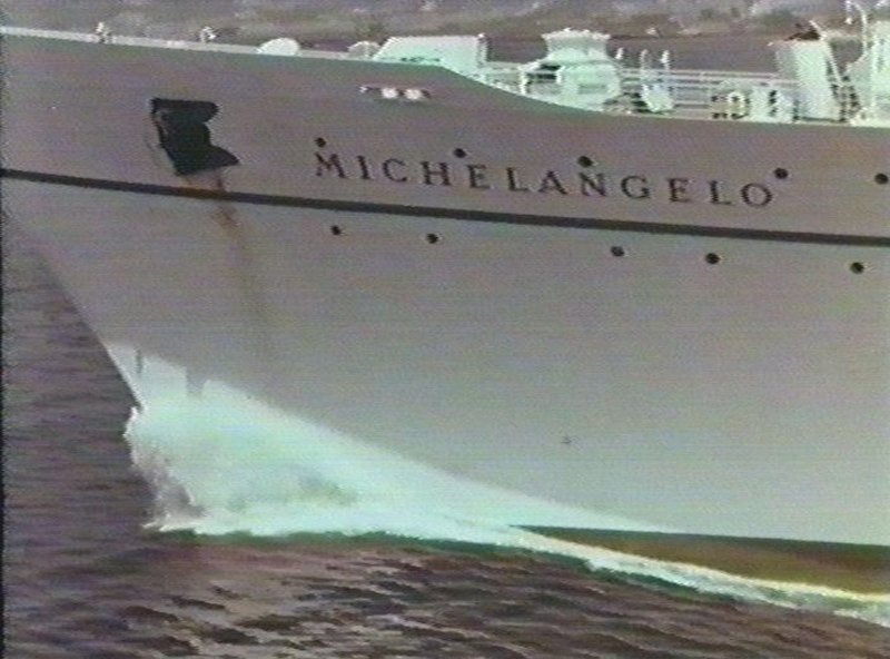
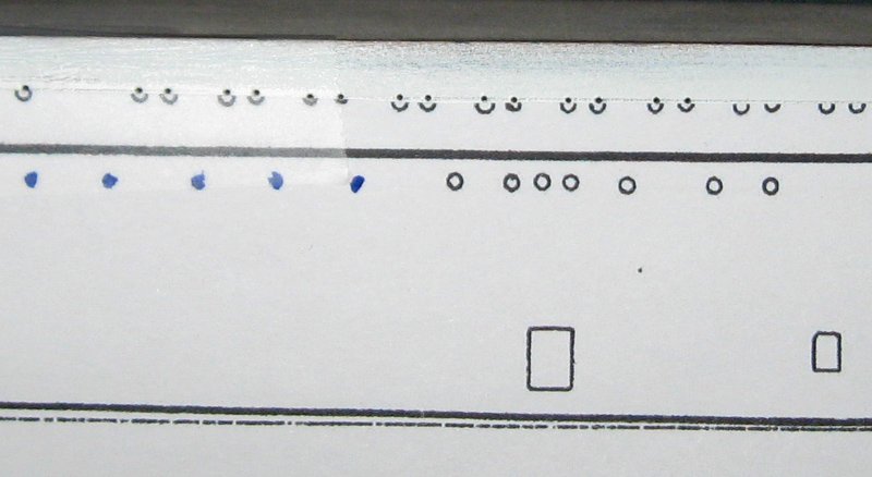
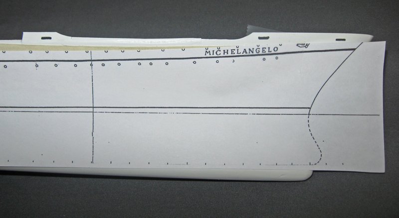
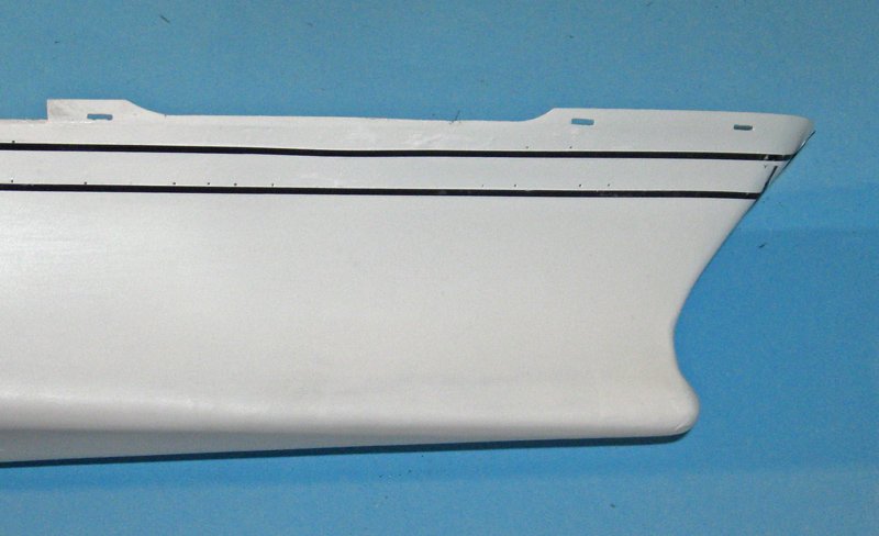
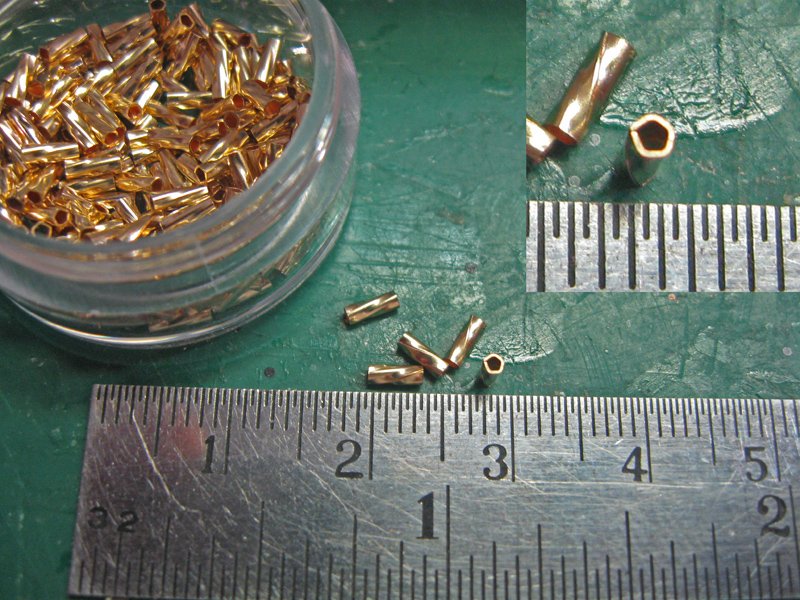
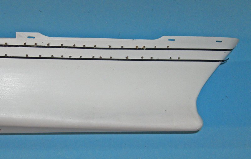
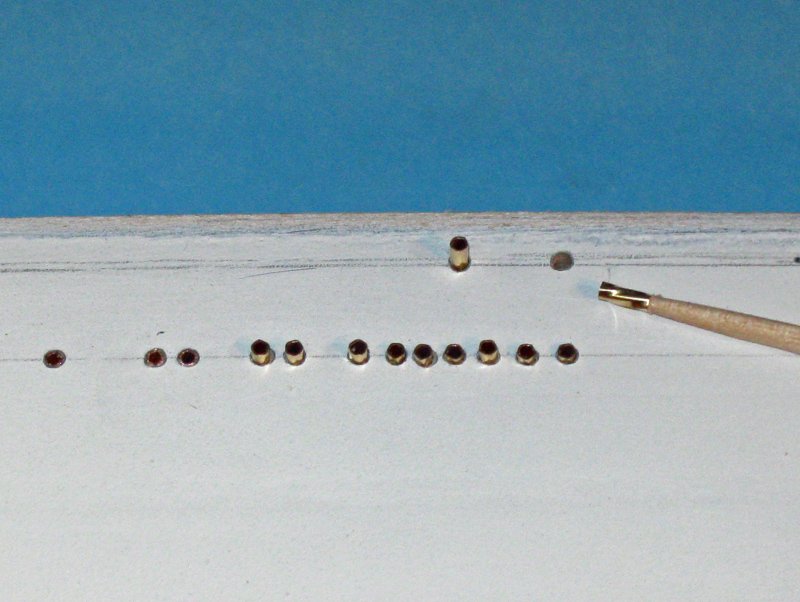
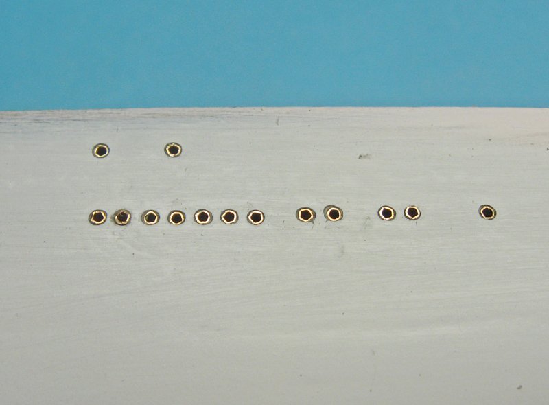
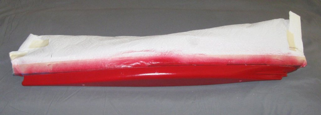
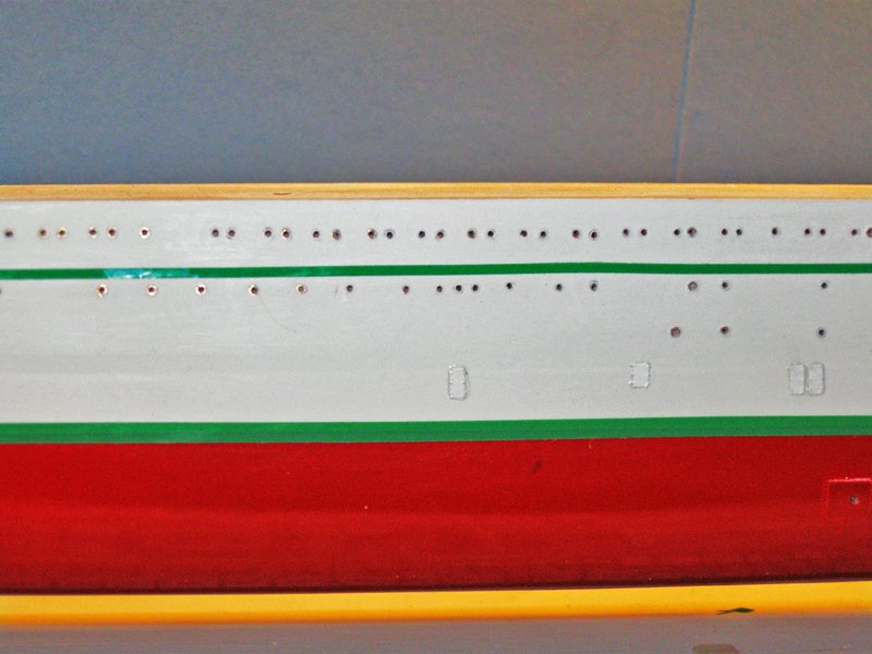
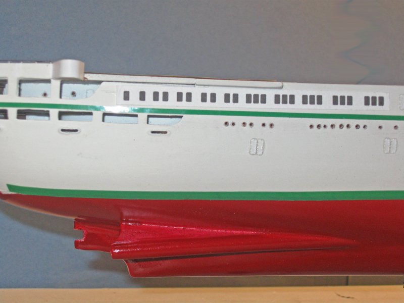
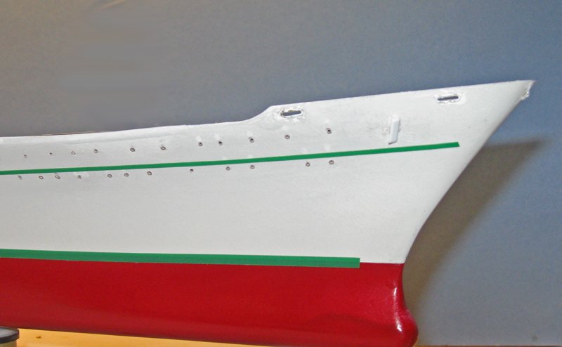
Hi all – Thanks again for the compliments and likes. I have to say that the questions and discussions always stimulate my mental juices. Keep them coming, and please don’t worry about pointing out things that can be improved. It is always better to hear about them during the building process when they can be corrected. The last segment ended with the hull smoothed and primed. Next came the process of detailing it. In the two photos below you can see that the surface was very smooth. Construction was done with welded plates, edge joined rather than having strakes of overlapping in-and-out plates as earlier ocean liners had. This meant that the hull would be simpler, but what was done would have to be more precise. This was especially true for the two lines of portholes. Which are the most obvious features other than the ship name and the green detail stripe. Close examination of these and other photos, as well as the plans, indicated that the lines of portholes followed the curve of the sheer. None of the photographs of the portholes show any detail, no matter how close the photograph was taken or how much I enlarged it. They simply look like holes in the hull. I am sure that there were small lips around them, but I never could see any. The first step was to offer up the plans to the hull and to compare the porthole locations on the paper, one by one, to the portholes that I could see in the photos. It turned out that the plans did not show some 15 portholes on either side of the hull. They were marked on the plans for future use. Then the plans were cut right through the top line of portholes and taped to the hull. As you can see, the line on the plans wanders a bit up and down, so the plans could not be used “out of the box.” Using a compass, the distance from the sheer edge of the hull block to the first line of portholes was set and a light line drawn along the length of the hull. An awl was used to make starter holes along the pencil line at each porthole location. At the bow the flare of the hull pulled the plans up, so the portholes would have ended up too high on the hull. The curves also made it impossible for me to just use the compass to set the line. My solution was to apply 1/16” black striping tapes just below the porthole locations. I could apply them, eyeball them, and adjust them as needed to get two matching sets of straight lines on both sides of the hull. The plans were then used to set the horizontal locations for the portholes, and starter holes were made with the awl. I next had to decide how the portholes were going to be modeled. Since they had no detail, I could have simply made holes in the hull. I tried it on some scrap, but the edges of the holes often came out ragged. This was unacceptable. A sleeve of some sort would solve this. In prior models I had used small brass grommets, but I could not find any which were small enough. They had to be around 18” in scale, or about 0.05” on the model, for the interior diameter. The length was less important, but something around 3/16” would be good for ease of handling. I could have sourced some brass tubing and cut off individual pieces. I even have a powered cutoff saw that uses an abrasive disc rather than a saw blade. But making over 500 of them without burrs or flash which would need additional cleanup was not something I wanted to try. Instead, I found 1mm x 4mm fluted brass beads on the Fire Mountain Gems website. This was a perfect size, but when they came in I saw that they were not perfectly round. The fluting process turned them into rounded pentagons. The difference was only visible under magnification, so I decided to use them. The outside diameter of the beads was 0.060” at its largest, so an 0.062” drill was used to make all of the holes in the hull. A toothpick was the perfect size to pick up a bead and slide it part way into a drilled hole, leaving them proud of the surface. The friction fit between the beads and the holes was probably enough to secure them, but the sides were painted with dilute white glue to be sure. Then a small tack hammer was used to set them down flush with the hull. Before the glue set the line was eyeballed and any beads that were slightly high or low were nudged into proper place. The hull was given another coat of primer to blend in the portholes and fill any small gaps around the beads. When I was satisfied the upper hull was given a final coat of gloss white. The paint was left for 24 hours to dry, then the upper hull was masked at the waterline with tape and paper towels. The lower hull was painted an OSHA red that closely matched my best color photos of the hull. At this point it was only a few days till the Joint Clubs Conference on April 29, so I did a few things a little out of sequence to make a better impression. Photoetched brass doors from Gold Medal Models and Tom’s Modelworks were painted white and applied to the hull following the locations on the plans and photos. Self-adhesive green striping tapes were applied to the hull. The one at the waterline is 1/8” wide, while the upper decorative one is 1/16” wide. These green stripes are only temporary. Although they are the right color, they are a bit too thick and the upper one is a bit too wide. The thinner tapes do not come in the right color, so I may have to take thin white tapes and paint them. More on this later. Similarly, the windows here at the stern are paper place-holders until I can make up the custom decals that ultimately will be used. At the bow I can see that some touch-up work is needed, but nothing that can’t be accomplished with a bit of elbow grease. So here she is at the conference again. The prominent line of windows of the promenade deck have been printed on pieces of paper to test the fit. The paper ones will be replaced with laser-cut ones done in either 0.020" styrene or a thin plastic-impregnated circuitboard material. Unfortunately, she has to be set aside for a bit so I can complete the QAR. I will pick her up again when I can. Until then, be well. Dan


- 287 replies
-
- 14
-
-
- michelangelo
- ocean liner
- (and 1 more)
-
Hi Nils - It doesn't look like your material took the sharp bend that it has to at the top edge of the bulwarks. You might try burnishing the foil down with a hard, smooth tool. A burnisher for the bookmaking craft would be best, but anything smooth and curved will do, including the back of a small spoon. You may need to use thinner material, as Gerhard suggests, but you could try this first. Dan
- 2,625 replies
-
- 5
-
-
- kaiser wilhelm der grosse
- passenger steamer
- (and 1 more)
-
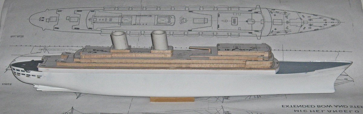
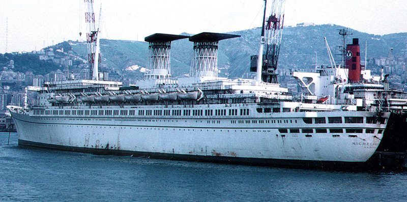
Hello all - Just a quick photo for those who could not make it to the Joint Clubs Conference in New London last Saturday. Bob Marvin brought me the funnel cages from Shapeways. They were perfect. Here they are, temporarily set on the rough cut superstructures. They need no sanding, just priming and painting. In the fullness of time I will fill them with the multiple tubes and struts of the funnel pipes. As you can see, there has been some more progress on the hull, but I have not had time to write up the log. More soon. Dan

- 287 replies
-
- 14
-
-
- michelangelo
- ocean liner
- (and 1 more)
-
Hi Dan - This may be your first scratch-built model, but you clearly have experience and skills. Nice, tight joinery on the keel and stem. I will be following along and enjoying your photos. Best of success with the project. (another) Dan
-
Hi Jay - I completely agree with Popeye and Jorgen. There is little sense in worrying about perfect historic accuracy for a model of a ship that never existed. The best that we can do is to include all the deck furniture and machinery that would be needed for a working vessel of the period and the place. For that, the books of Howard Chapelle are an excellent source. He was a trained marine architect and did many of his drawings and plans after looking at the actual ships and boats. Of course, as Jorgen says, individual variations are up to the builder. Best of success with the project. Dan
- 714 replies
-
- 3
-
-
- lady nelson
- victory models
- (and 1 more)
-
Jay - Sounds like you are learning lots of good lessons, including how to adapt, adjust, and overcome issues as they come up. Spreading out the adjustment of the port planks was an excellent idea. Looking forward to seeing your progress. Be well Dan
- 714 replies
-
- 5
-
-
- lady nelson
- victory models
- (and 1 more)
-
Hi Jay - Just found this log and have enjoyed reading about your progress. It looks like you are steadily working your way up the learning curve, and coming out with a nice model. A few planking suggestions learned by reading everything in sight and by trial and error this past 30 years - 1. The garboard strake, and even the next strake known as the first broad strake, flare at the stern on actual ships. On a narrow hull like a cutter this may eliminate the need for any stealers at the stern. 2. At the bow, keep the tip of the garboard plank low. The more it is allowed to rise up the stem the less room you will have for the upper planking strakes, so the more they will have to taper or you will have to use more drop planks. 3. Don't worry about locations of butt joints in the hull planking. They were pretty much random, and governed by the availability of various plank lengths. The only general principal is that you do not want butt joints on the same frame unless they are separated by two or three solid strakes. The 3 and 4-step planking layout applies to the deck, not the hull. 4. The best resource I have found for hull planking, deck planking too, is "Planking the Built-Up Ship Model" by Jim Roberts and available from Model Expo and/or other book sellers. Hope this helps a bit. Be well Dan
- 714 replies
-
- 8
-
-
- lady nelson
- victory models
- (and 1 more)
-
Michael - I was going to say that your work on the binnacle is superb. But if you are going to end up with a better one, I will hold off for now. I am in danger of running out of superlatives. Superb, nonetheless. Dan
-
Hi all - Thanks so much for the compliments. There is a lot more experimentation on this ship than others at larger scales. Glad you think I have succeeded. Kenny - yes, I was thinking along those lines too, but getting a vacuum around something the size of the model was a problem I couldn't figure out. I will use your method for the lifeboats if I can't source satisfactory ones. Dan
- 287 replies
-
- 6
-
-
- michelangelo
- ocean liner
- (and 1 more)
-
Hi Nils Sweet work, as always. KWdG will make a wonderful and beautiful addition to your home. For situations like adding the molding to the bridge, I find that this method works for me: First, I shape the piece and dry fit it. When I am satisfied with the fit I clamp it into place with small clips. Once perfectly aligned, I tack it in place by introducing thin cyano in a few selected spots. It runs behind the piece by capillary action and any excess I quickly blot away with a light swipe of paper towel. When that first gluing is set, I remove the clips and check alignment again. If all is still OK I feed thin cyano all along the edge of the piece, blotting as before. No mess, no smeared paint, no glued fingertips. Hope this is useful for you. Dan
- 2,625 replies
-
- 4
-
-
- kaiser wilhelm der grosse
- passenger steamer
- (and 1 more)
-
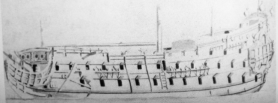
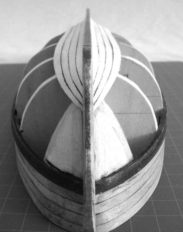
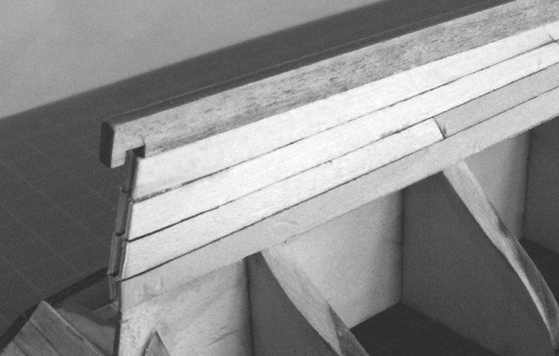
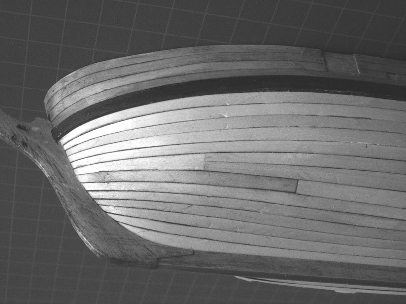
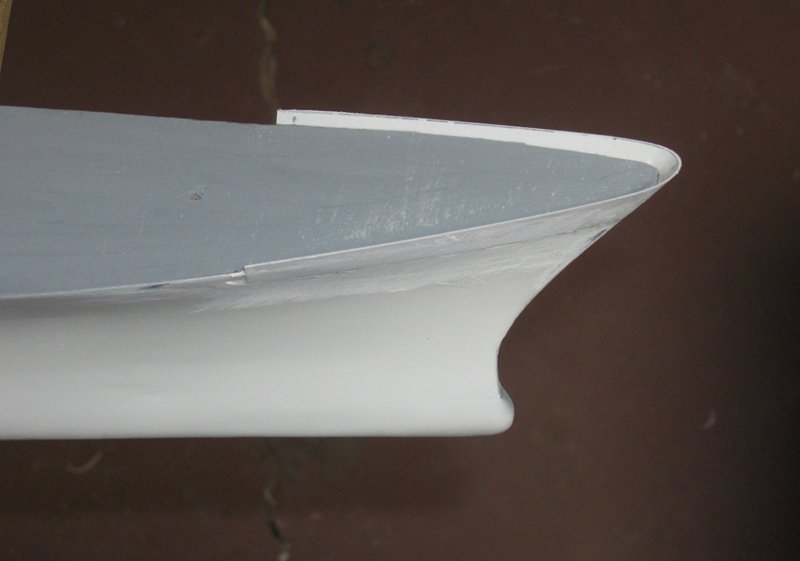
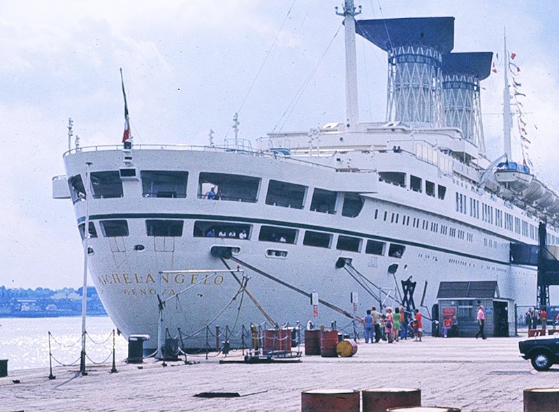
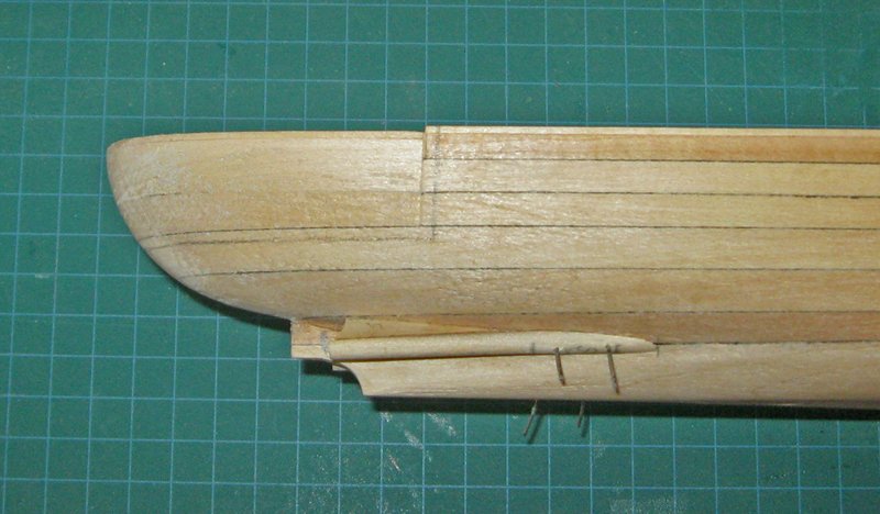
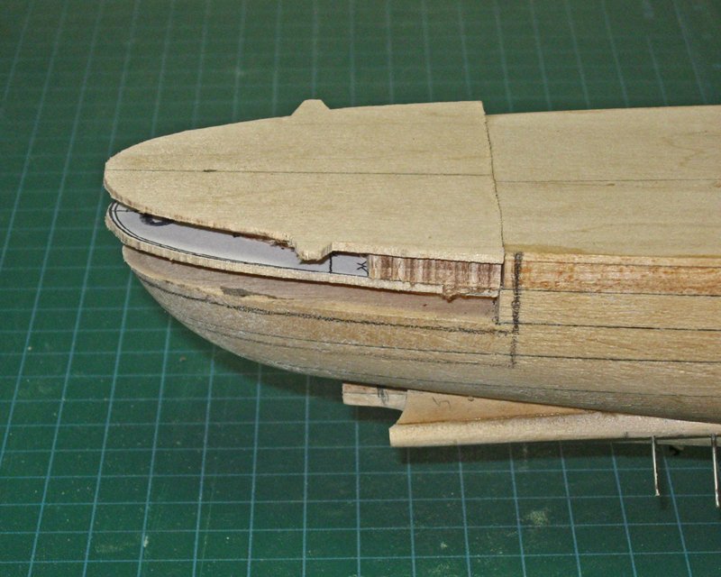
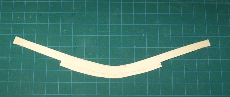
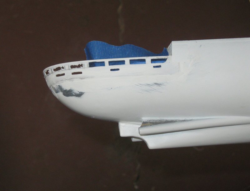
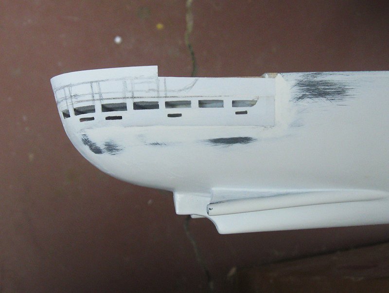
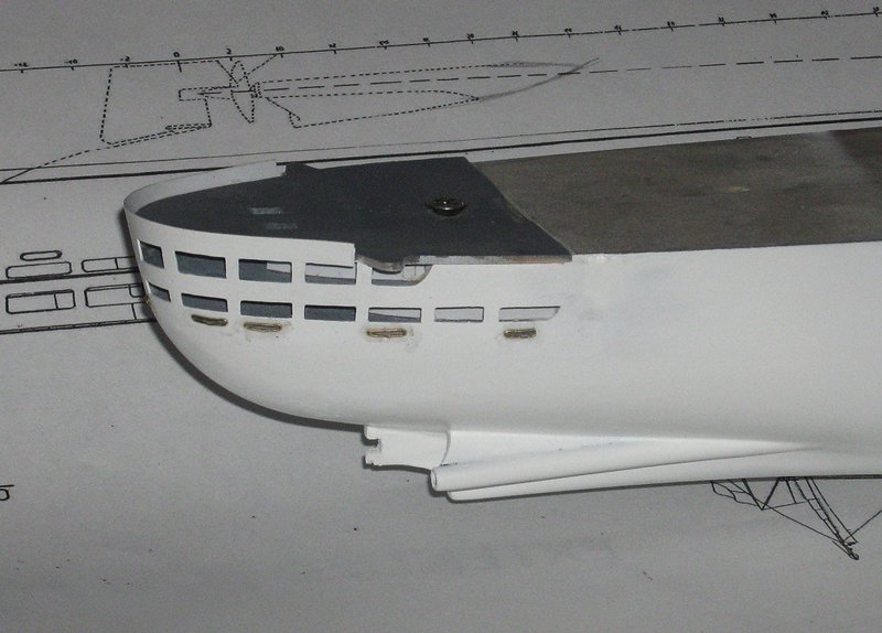
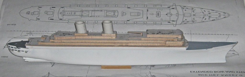
Hi all – I hope everyone has had a nice Easter, Passover, or other spring holiday of your choosing. Thanks, as always, for the comments and the likes. It is so nice to get feedback from our modeling family – both the in-laws and the outlaws. You can decide which you are. The last segment concluded with me working on the bow to get the shapes right and the surface smooth, as well as cutting and installing the flared bulwark pieces. While I continued to refine, smooth, and fair the bow, I turned to the challenges of the stern. As seen in the photo, it has a smooth, rounded, but flared shape with two decks that are each pierced with large openings for viewing. The lower ones are not as tall compared with the upper ones, or rather, the bulwarks are higher, as can be seen from the postures of the people looking out. In the upper openings the bulwarks are lower, but a single open railing is mounted on top for safety. This same solid bulwark and upper railing system is an almost universal design feature of the ship, and can be seen as well above the topmost bulwark at the stern. The lower deck also has a number of round and elongated hawse holes for mooring lines, so the bulwarks have to be pierced for them as well. All of this meant that the model’s stern would have to be some sort of pierced shell, like a lacework Easter egg. To get that shell I first tried to drape-mold styrene in one sheet. I had already built up a solid stern block which I hoped to use as the form. I screwed it down onto the hull block and made sure all the edges met. I then put a sheet of 0.020” styrene in a bath of simmering water. While it softened I heated the stern of the hull with a hair dryer. When I thought everything had reached a workable temperature I pulled the plastic out of its bath and pulled it down on the hull form. It did not behave. Pleats and wrinkles formed which could not be flattened. I tried several more times, making the plastic sheet hotter in an oven, moving around the points where I pulled on the plastic, etc. Ultimately I only ended up with half a dozen sheets of unusable plastic which had to be discarded. I will not embarrass myself by posting photos of the trash. I decided that I would have to build up and pierce each deck separately, and then work on the seam between them. This would be slower, but used techniques that I was already familiar with. I first had to establish the shape of the stern with just the deckhouses and decks stacked together to get a feel for the internal structures. They were cut according to the deck plans, but a little oversize, and were temporarily screwed to each other and the hull. These pieces were faired to each other with a sanding block, checking frequently to see that they created the flared shape desired. When I was satisfied, the upper wooden pieces were taken off, leaving only the lowest deck house and deck. A piece of cardstock was used to make a pattern for a curved piece of plastic sheet, much like the one that was created for the bow bulwark. The plastic was cut oversize and then refined by trial and trimming until it fit well. As at the bow, a rabbet was cut into the solid hull to bed the edge of the plastic into. The piece was secured with gap filling cyano. When the glue was solid the gaps at the edges were filled with Squadron white putty in several layers to build up the filler to compensate for shrinkage as it dried. Then the surface was sanded flush with the hull, with special care being taken at the edges. You can see where my smoothing process went through the layers of white primer and into the grey primer below. The color change proved to be a good warning that I should not go deeper in that spot. Then the locations of the window openings were drawn on the plastic in pencil, and the centers were ground out with a small burr, staying well away from the lines. A sharp #11 knife was used to carefully whittle away the remaining plastic until the openings were the proper sizes and shapes. The hawse holes were done in a similar fashion. From there I repeated the process for the upper deck. But first, the lower deckhouse and the underside of the lower deck were painted and permanently installed. At this point I was committed. It was no longer easy to remove the stern pieces and redo them. As before, a cardstock pattern was created, plastic sheet was cut and fit, glued into the rabbet and faired to the hull and the lower deck bulwark. The viewing openings were drawn on, pierced and whittled away as before. In the previous photo you can still see some spots where additional refinement and whittling of the lower openings is needed. This was a continuing process and done very carefully. A slip here might mean that the entire piece would have to be stripped out and replaced. Fortunately, it ultimately came out as I wanted. After a coat of primer it is, I believe, quite difficult to tell that it was pieced together. So here is the current state of work, with the rough superstructure laid on. It sure will be great when I can replace the plumbing pipe funnels for the lacework cages that Bob made up. Can’t wait. But there are many more miles to go before I can reach that point, and many more postings. Until the next one – Be well Dan
- 287 replies
-
- 21
-
-
- michelangelo
- ocean liner
- (and 1 more)
-
Nils - She gets more impressive with each posting. What will be her final port of call? Dan
- 2,625 replies
-
- 5
-
-
- kaiser wilhelm der grosse
- passenger steamer
- (and 1 more)