shipmodel
-
Posts
941 -
Joined
-
Last visited
Content Type
Profiles
Forums
Gallery
Events
Everything posted by shipmodel
-
 Hi Ken, and Happy New Year - The detail work is coming along very nicely. Congratulations. As for the carved canines (hounds has another nautical meaning), you might try stiffening them with Minwax wood hardener before doing more detailed carving. It dries clear and does not seem to interfere with gluing strength. It makes carving a bit harder, but significantly reduces breaking along the grain. Of course, test on some scrap before letting the dogs out. Be well Dan
- 481 replies
-
- 2
-

-
- rattlesnake
- model shipways
- (and 1 more)
-
Hi Ken - Belaying was always somewhat flexible and could be changed at the discretion of the captain. So if you want to add kevils, that would not be an inconsistent thing to do. That said, I have rarely seen a lot of kevils on a ship this small. For what it is worth, Lees has a belaying chart for a Frigate of about 1810 which gives the belaying point for the fore yard lift as being "Fore jeer bitts". The main yard lift goes to the "Second pin of the main pin rail". The crossjack yard only has a truss pendant and braces, since it did not move up and down. The model of the Rattlesnake by William Hitchcock, which I have seen a few photos of, has pinrails and shroud cleats, although there could be some kevils which are not in view. Your ship, captain. Your choice. Dan
- 481 replies
-
- 1
-
-
- rattlesnake
- model shipways
- (and 1 more)
-
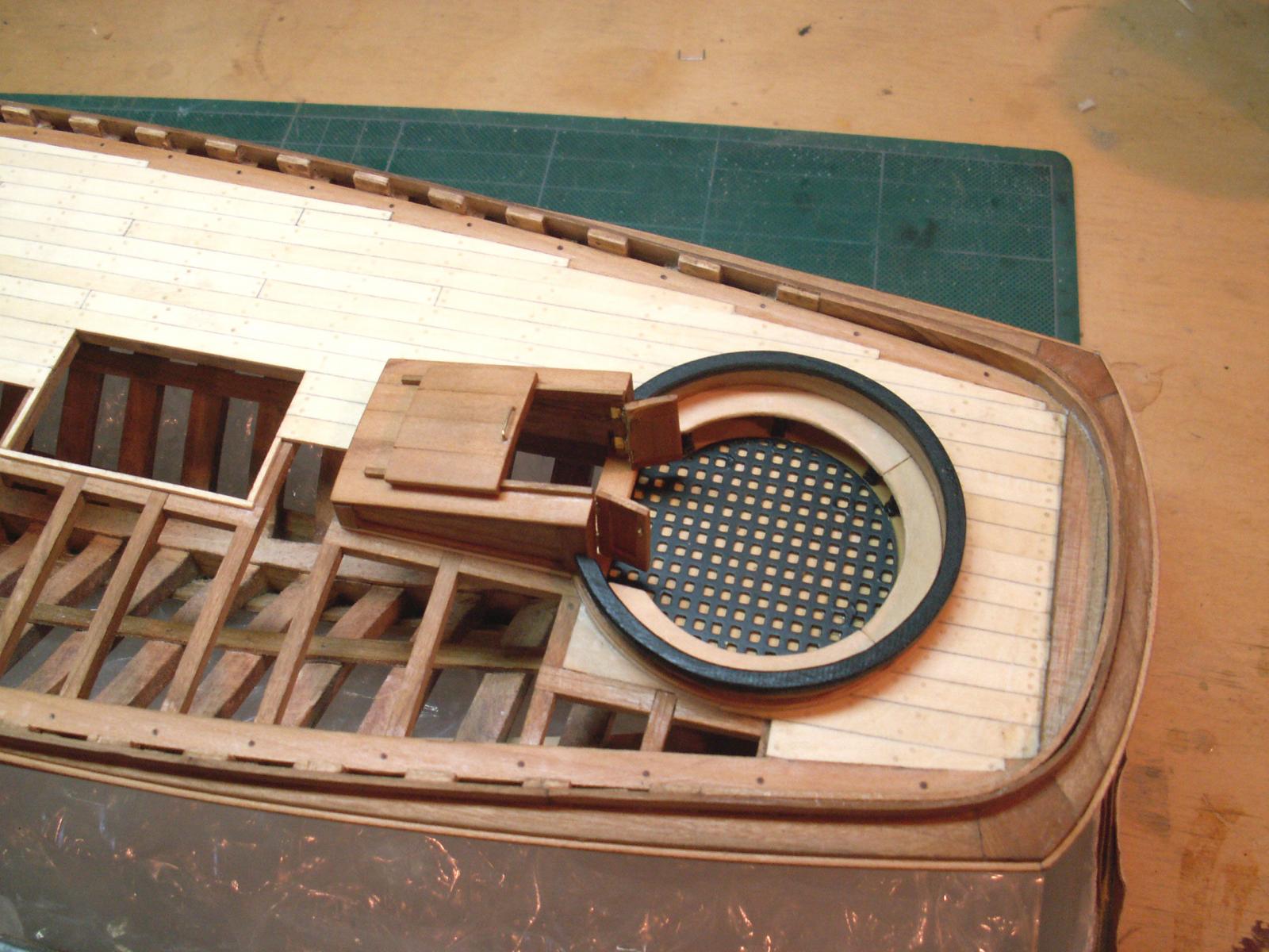
Hi Mark - That planking is coming along very nicely, and that is not easy with the odd shape of French hulls from that period. Well done Dan
-
Teriffic progress. The black really sets off the lettering and the portholes. Sweeeet. Dan
- 2,625 replies
-
- 4
-
-
- kaiser wilhelm der grosse
- passenger steamer
- (and 1 more)
-
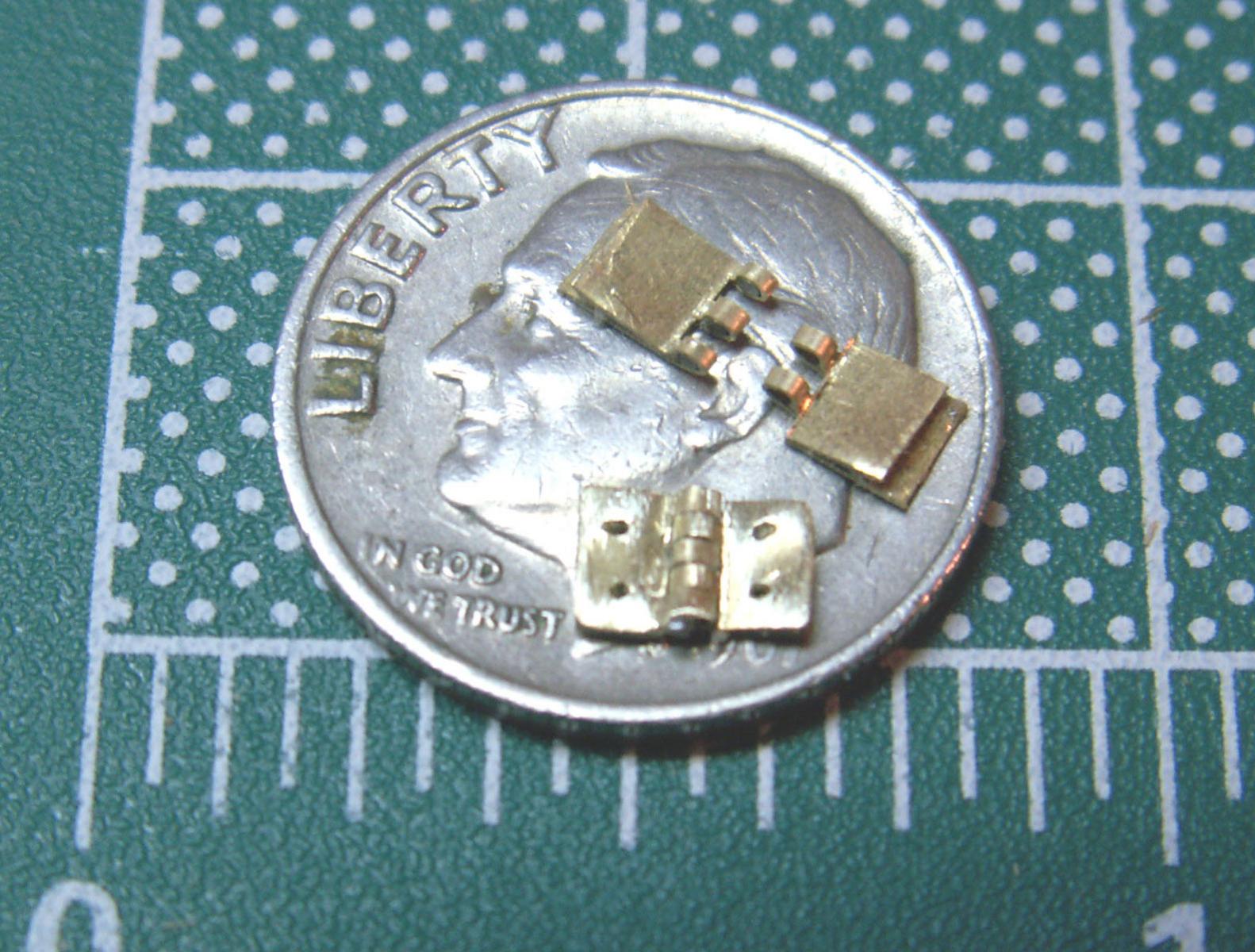
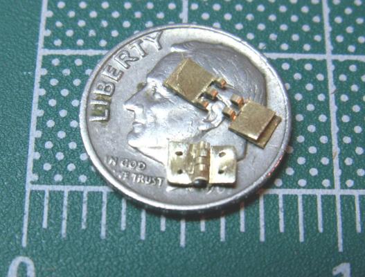
Hi Michael - Really nice hinges. I used a similar method to make working hinges for the companionway door of a yacht America model some time ago. I do not have your skill with a jeweler's saw, so I used a length of soft iron wire inside to form the hinge barrels, and then cut straight through the whole thing with a metal cutting blade in the Preac. I think they came out pretty well. Either great minds think alike, or fools rarely differ, whichever one applies. :-)) Dan
-
Beautiful work, Nils, especially the bow decorations. Is your sailor cursing the gods or just shielding his eyes from the sun? Dan
- 2,625 replies
-
- 5
-
-
- kaiser wilhelm der grosse
- passenger steamer
- (and 1 more)
-
G'day all - And I say that because three of the comments are from Oz, and the other from Canada. Hard to remember how hard it was to make a long distance call to the next state, and now it is routine to be mates with friends halfway around the world. Amazing . . . Greg - yes, I will post a link and set it up on my profile. John - I did put in a binnacle, but I have no idea if the telegraph is right. It just seemed that the spot needed something, although it could have been a telephone station. etc. . . I never found any clear evidence, and I am not enough of an ocean liner expert to know. Never even heard the term "monkey island" before, but it's a perfect description. Dan
- 108 replies
-
- 6
-
-
- andrea doria
- ocean liner
- (and 1 more)
-
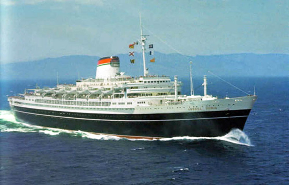
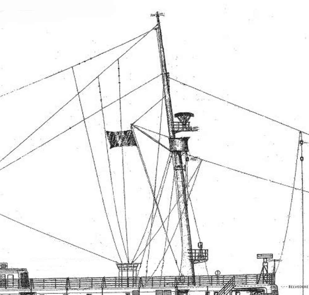
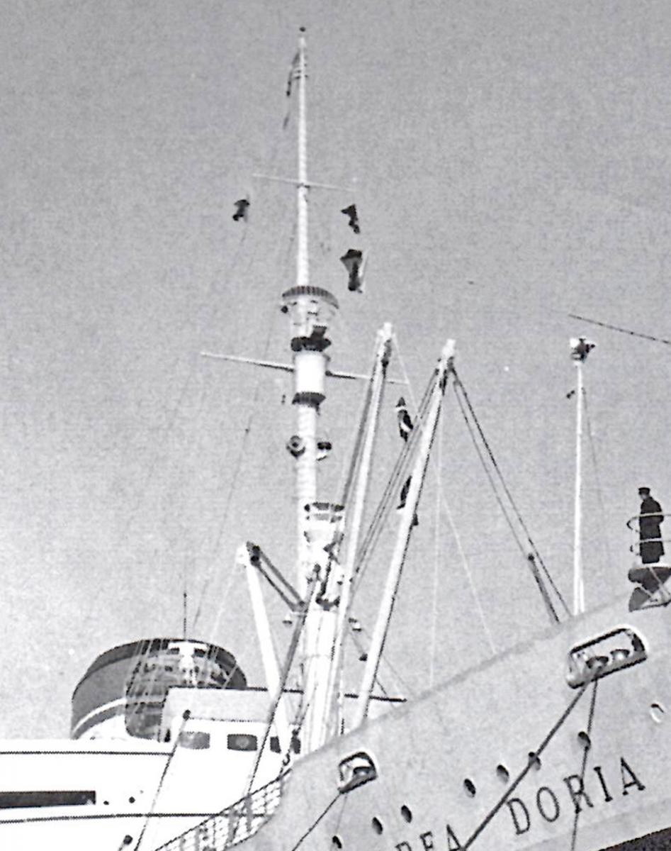
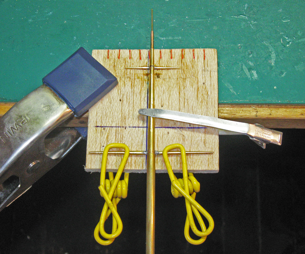
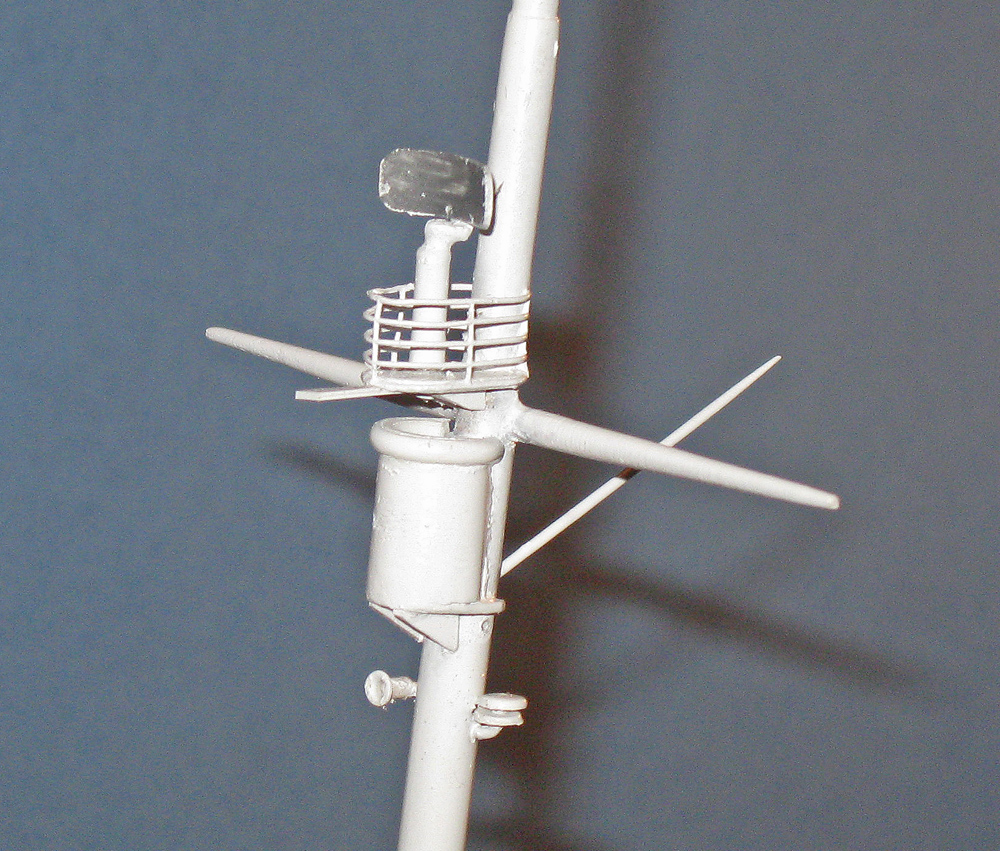
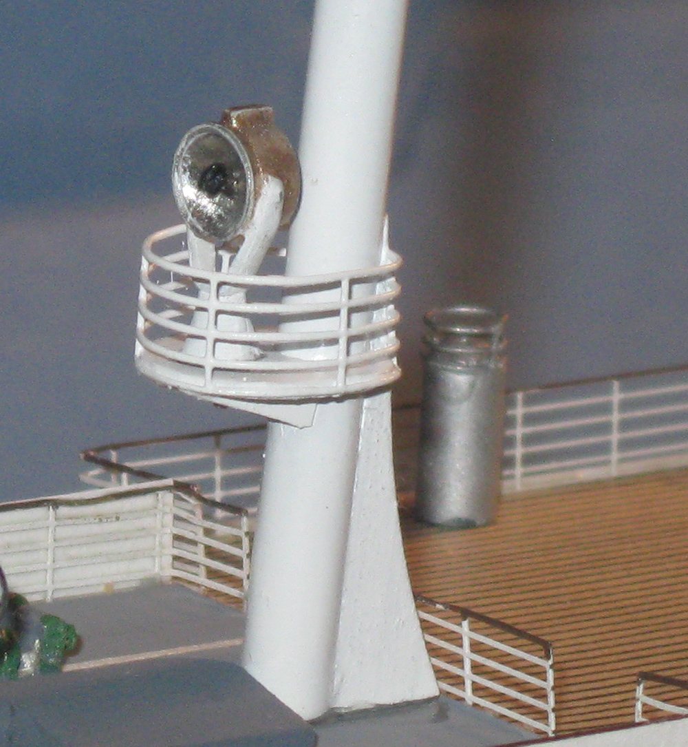
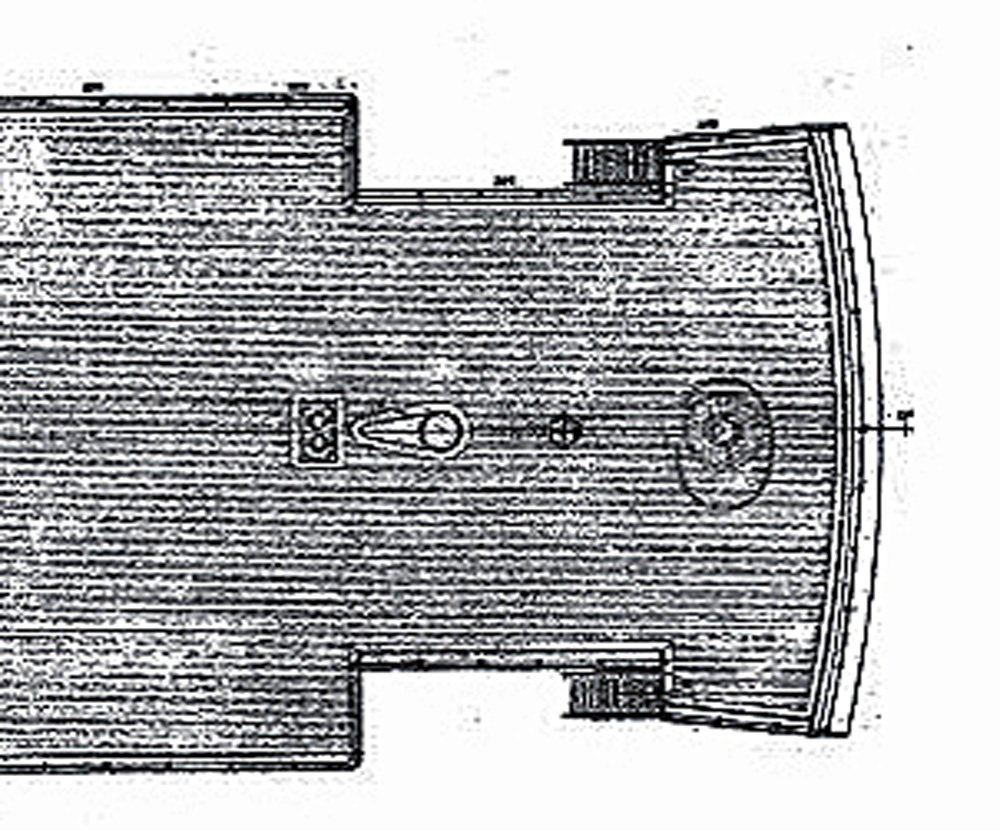
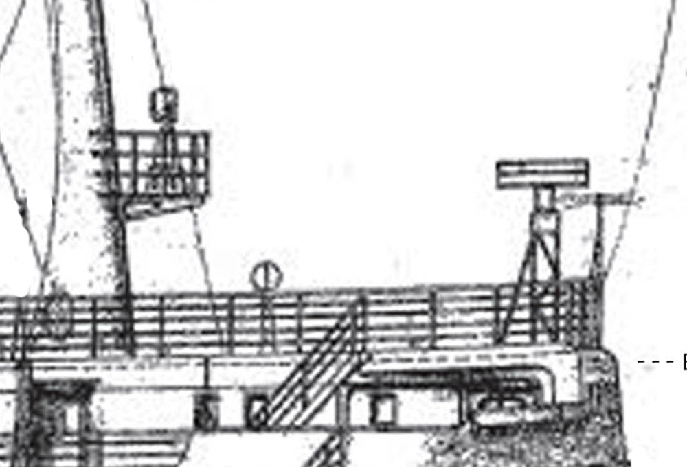
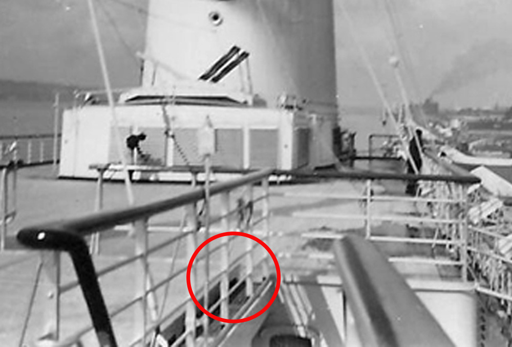
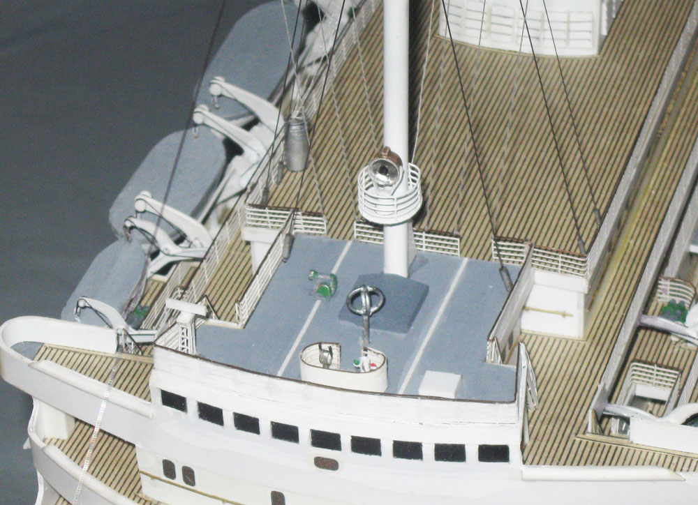
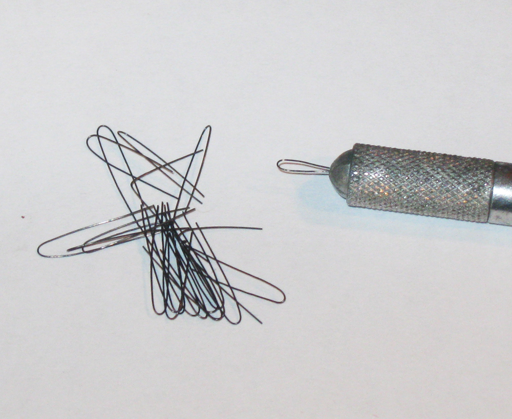
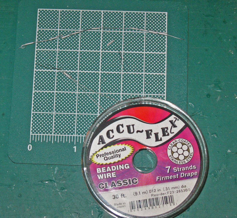
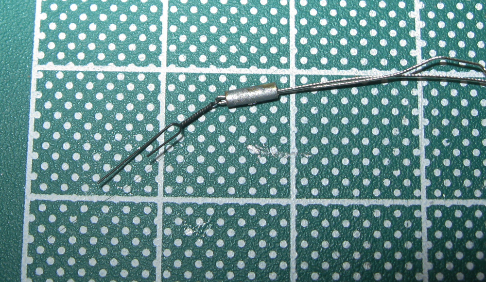
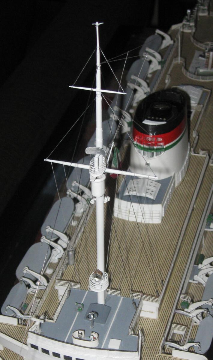
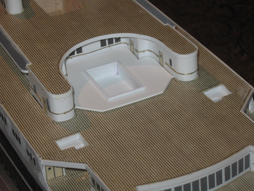
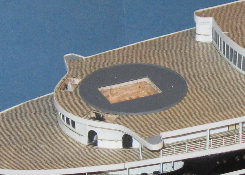
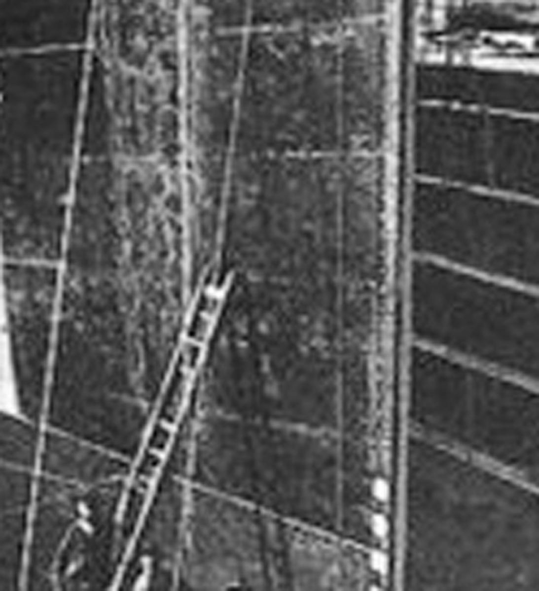
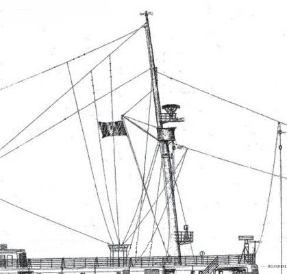
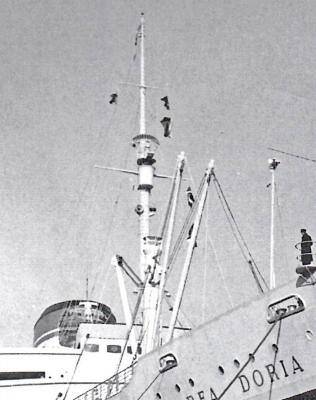
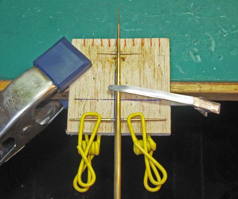
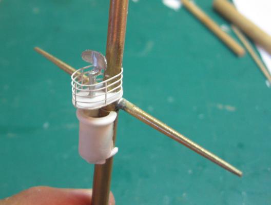
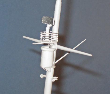
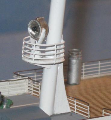
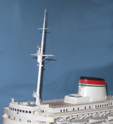
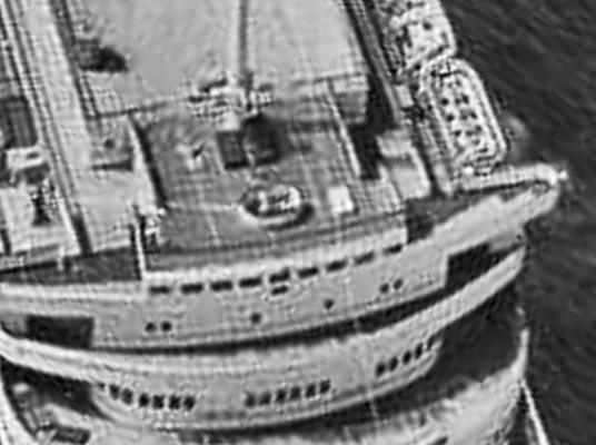
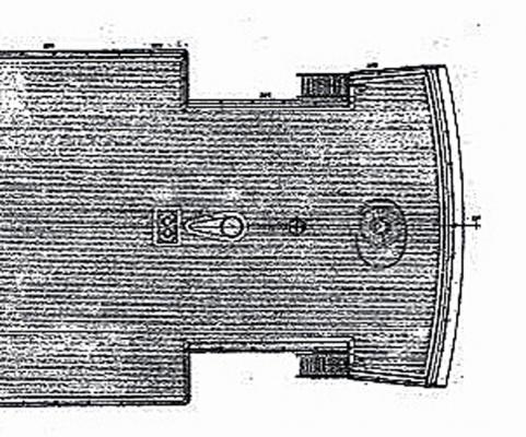
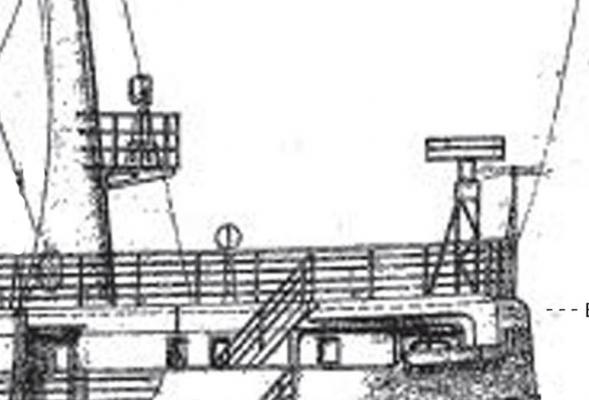
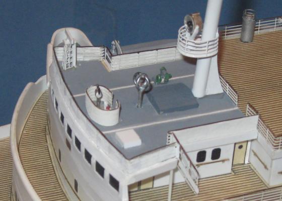
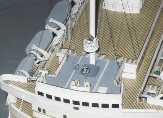
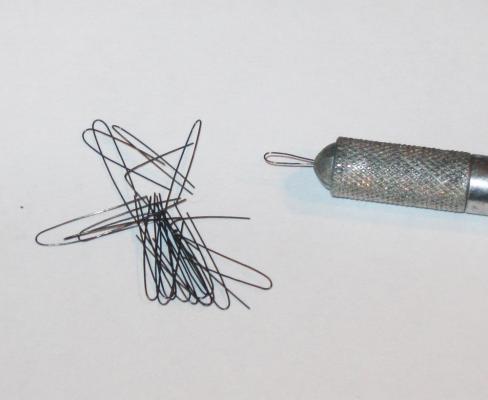
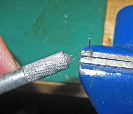
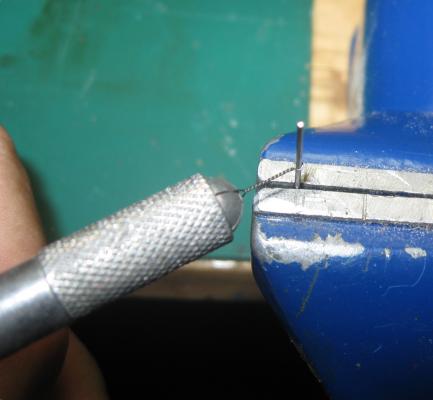
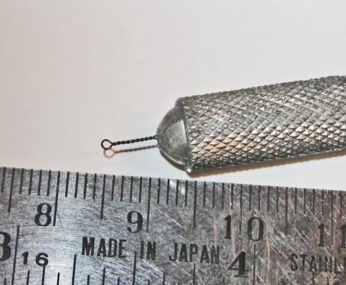
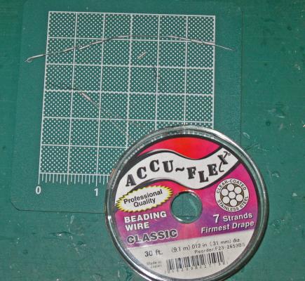
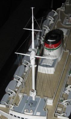
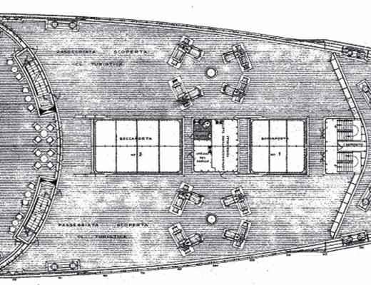
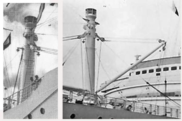
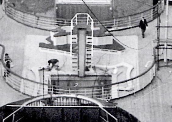
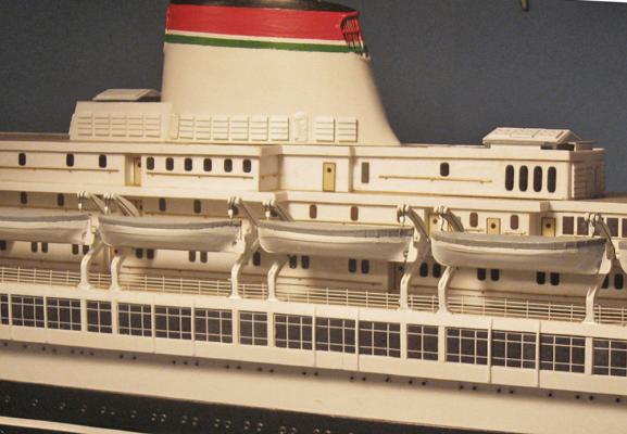
Build log 14 – lookout mast and command deck Thanks, as always, for the likes and comments. Greg, I’m sorry too that it is coming to an end, but I will be back with another project sometime soon. Happy that you have been enjoying the voyage. The final major visual component of the ship is the tall mast that supports the lookout post, radar position, and a searchlight platform. It was also used to hang the radio wires as well as signal and display flags. As you can see, it reaches way up, to almost three times the height of the funnel. From the plans the basic dimensions were taken, as well as the sizes and locations of the radar, lookout, and searchlight stations. The mast itself is tapered, but seems to have a number of steps, rather than a continuous surface. The gaff for the flag halyard is shown, but not the large and small yards that cross the mast. There are a few small fittings whose shape and purpose have yet to be determined. This is the best detailed photo of the mast. Although the searchlight is hidden behind the cargo crane, the rest of the details are pretty clear, including a horn on the starboard side of the mast below the lookout station, and a small fitting, still unclear, to port. The two spars can be clearly seen, so their sizes and locations were taken from the photo and not the plans. The mast was built up from 6 lengths of thin brass tubing that telescoped into each other, topped by a final section of brass rod. Where they come together the larger, lower, tubing was tapered so there would not be a distinct step between sections. These were soldered together to match the plans. The base was filled with a wooden dowel so a brass rod could be inserted to support the mast on the model. 1/8” and 1/16” brass rods made up the spars. They were given a double taper in the drill press by grinding with a stone wheel in a Dremel. The high grinding speed achieved by positioning the rotations against each other made quick work of the job. The surfaces were smoothed with a fine file to prepare them for soldering. First, a 1/8” half-round channel was ground across the mast and the lower spar was soldered into it. A second channel, 1/16” wide, was ground into an upper segment for the topmast spar. Using just a scrap of wood and a few clamps the upper spar was held down on the same plane as the lower spar and soldered into place. Unfortunately, only after everything was solid and true did I review the photo to discover that although the upper spar is mounted to the front of the mast, as if it were a sailing ship, the lower spar mounts to the back of the mast. This must have been to allow room for the crew to climb an internal ladder to the lookout platform. I thought that I might have to scrap the mast already made, but I was able to unsolder one of the joints between the two spars and rotate the top 180 degrees, which fixed the problem. The lookout station was built up from a flat base with a section of tubing above it. The back ends of both were cut and ground to fit tightly against the mast. This was detailed with a rim of half-round strip at the top edge, and two small support triangles below. The radar platform has a base made in a similar way, with 4-bar railing wrapped around it and a Bluejacket casting of a radar dish cleaned up and detailed. The radar post was too short, according to the photos, so it was removed and a taller shaft was fashioned from plastic tube. The horn and the other fitting were made up and inserted into holes drilled in the mast below the lookout station. A tapered brass rod made up the flag gaff. In the photos I could see a flat tongue that extended out from under the radar platform. I have seen similar fittings above lookout posts on other ships that do not have radars, so this must have something to do with the lookouts. Perhaps it provides a way to block the glare of direct sunlight, but I just don’t know. Perhaps one of you with more experience with liners can fill me in. The searchlight platform was constructed in a very similar manner. I used a casting for the searchlight, adding a bar on top. The reflector was ground smooth with a round carving bitt, the unpainted white metal making a convincing silver appearance. The central light source is a tiny nail inserted into a hole in the reflector and touched with black paint for contrast. The bronze color for the body of the searchlight may not be strictly correct, but it makes the fitting stand out in a way that I like. So here is the finished mast, painted and installed. At the base of the mast, the forward end of the Sun Deck is separated by a railing and has a number of fittings and structures. I call it the Command Deck, but this is just my personal notation. Here is the best photo that I found, which is not too good. Further enlargement pixillates it and the detail is lost; reduction makes it impossible to see those details. It is clear that the Command Deck has a different surface than the rest of the decking, but what it is made of is unclear. On the deck there are six elements in addition to the mast. First, an oval structure which looks to be surrounded by railing in a position usually reserved for a captain’s post. In the forward starboard corner is a radar with a flat receiver, seen better in the earlier photo of the mast. The rest are open for interpretation and speculation. The plans are not much help. In the deck plan there are just three elements shown with the mast along the centerline. The captain’s oval shaped station is forward. Next is a cross in a circle, which from other evidence seems to be a radio direction finder, I think. Behind the mast is a rectangular fixture whose purpose never became clear, and which never appeared in detail in any photograph. The deck is shown planked like the rest of the Sun Deck, which is clearly not how it was. In profile, the plans show the radar and the radio direction finder, but nothing else. I was just going to paint the Command Deck a light grey to match the lifeboat covers until I found this photo. At first glance, the fact that all of the handrails were at the same height led me to believe that the Command Deck was flush with the level of the Sun Deck. But then I noticed, in the red circle, that the corner of the deck is raised about a step above the Sun Deck level and built up inside the railings. This one small view, out of all of the plans and photographs of the ship, was the only indication of this construction detail. This is why I go back and back to the photographs, and I still get things wrong. After making a paper pattern I cut out a sheet of plastic 1mm (8 scale inches) thick and laid it in place inside the railings. On it are my interpretations of the several elements. The captain’s post has a telegraph and a binnacle. The radar sits on a tripod mast. The radio direction finder was made up from a brass rod and two split rings cut apart and soldered together. The rest are shaped to match my interpretations of what I can see in the photos. They match the shapes and sizes, although I am far from certain what their exact nature and functions are. With the Command Deck done I could add the shrouds to the mast without them getting in the way. There are three to each side, with the lowest being the thickest and mounted furthest forward. Each was secured to the deck under tension with a turnbuckle as seen in the photos. Since these turnbuckles are less than ¼” tall, I made them up simply, but I think they give a fairly convincing appearance. The turnbuckles are secured to the deck with very small eyebolts that still have to be quite strong and secure. Here is how I made them. I have explained this in other build logs, but the method works so well that I thought I would go over it again. I cannot claim that this is entirely my development, just a small improvement over what others have come up with. Soft iron wire is cut into lengths about 1 ½” long. When I have 20 or so they are held together and bent in the middle to form tight “U” shapes. The legs of one are slid into the blade slot of a hobby knife handle and tightened. As long as the legs do not cross each other inside the handle the wire cannot be pulled out easily. It is the use of the handle that is my new wrinkle. Not a great advance, but it works for me. A drill bitt of the desired inside diameter of the eyebolt is selected and secured upside down in a vise with the shank sticking up about half an inch. The wire is looped over the bitt. Pulling back gently to maintain tension, the handle is rotated to start the twist that forms the shank of the eyebolt. The twist is continued, under tension, until the wire tightens around the drill bitt and the twisted shank reaches the head of the handle. Using the handle allows me to spin up the shank very easily and quickly, much more so than other tools that I have seen used for the same purpose. The formed eyebolt can now be slid off the drill bitt and released from the handle. Once you have the technique down, it takes only a few seconds to make one up from the bent wire to the finished eyebolt. This one has an i.d. of 0.030” and was made with wire 0.015” thick. I have made them even smaller, and much larger, using this same method. To use the eyebolt, the shank is clipped to the desired length and secured in a hole with a drop of glue. The twists in the wire help the glue grip the shank, forming a very strong rigging point even when the shank is less than 1/8” long. I wanted the shrouds to look like steel cable, so that is what I used. Accu-Flex beading wire is made of multiple stainless steel fibers covered in plastic. It comes in diameters from 0.024” down to 0.012”, which is thin enough for anything I have ever needed. A 30 ft. spool is less than $5, and 100 feet is under $10. It is available in a range of colors and metals to suit any need. The disadvantage to beading wire is that it is so stiff that any sharp bend in it forms a kink that does not go away. However, if gently handled it makes very realistic metal cables. To make up a turnbuckle, one end of the wire was threaded through an eyebolt and folded back on itself. A small section of brass tube was cut and painted, then slid down to form the body. In larger scales I have further detailed the fitting, but this is so small that it was not necessary. The excess wire was trimmed off and the shaft of the eyebolt cut to length. This first turnbuckle was secured into a hole in the edge of the deck. On the other side the corresponding eyebolt was installed without the turnbuckle. I had previously drilled three holes through the mast at the attachment points for the shrouds. When the eyebolts were set and the glue dry the cable was fed through the appropriate hole in the mast. A turnbuckle body was slid on and up and the free end of the cable was led through the empty eyebolt. Pulling up strongly to tension the system the cable was crimped around the eyebolt. The free end was threaded back up through the turnbuckle body, which was slid down to trap the end without releasing the tension. Drops of glue secured the second turnbuckle and the excess cable was trimmed. A stay was made up in a similar way from the largest beading wire and run from near the top of the mast to an eyebolt and turnbuckle in the bow. The rigging to the mast was finished with lifts for the spars and the ensign gaff. The beading wire was too stiff to make tiny knots, so polished threads were used, then painted with steel colored enamel. Here is the finished and rigged mast. It is best seen if you click on the photo to enlarge it. In the photo you can see some of the lines for the shortwave radio antenna. In the next segment I will go into them and some of the other penultimate details of the model. Be well Dan


- 108 replies
-
- 18
-
-
- andrea doria
- ocean liner
- (and 1 more)
-
Really coming along well, Charlie - I love that fact that you are checking your hull shape so often, and checking, and checking, and checking. That's the only way to make sure you get it right, or at least how you catch mistakes before they pile up on each other. For the planking, have you considered an outer planking layer of veneer, then a middle layer of 1/16" wood for strength and to build up the thickness of the bulwark, and a final inner layer of veneer planking. That might eliminate the need for a carved notch along the length of the hull to fair the outer planks to the hull. Just another way to go. Dan
-
Hi Michael - There should be a term for that senior moment when I realize that the glasses that I am looking for are perched on my head !! Outstanding metal work, as usual. When you get all your photos together, it would be great if you could post your lessons here, or maybe even turn them into a book. Just get together with Bob Friedman at Seawatch Books and see what he says. I know I would be at the head of the line to buy it. Be well Dan
-
Cristiano - Thanks so much for pointing me to the site. The brochure confirmed that most of what I built is pretty accurate, so there is nothing that I have to rip out and replace. I have bookmarked the site and will certainly refer back to it when I do my next ocean liner. Dan
- 108 replies
-
- 4
-
-
- andrea doria
- ocean liner
- (and 1 more)
-
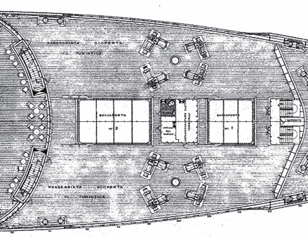
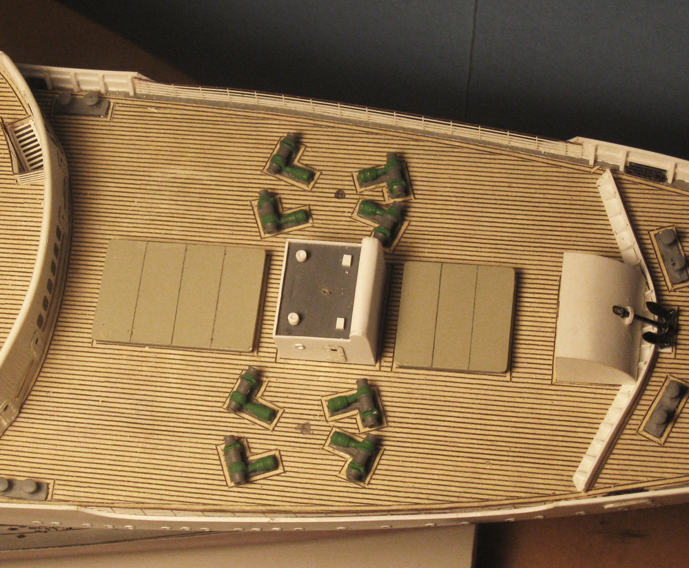
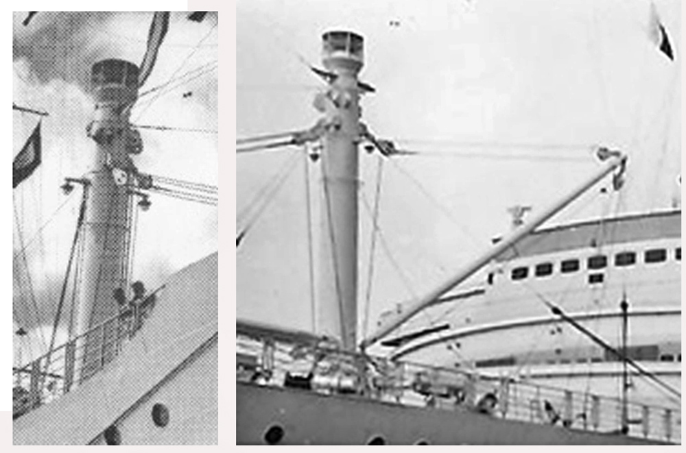
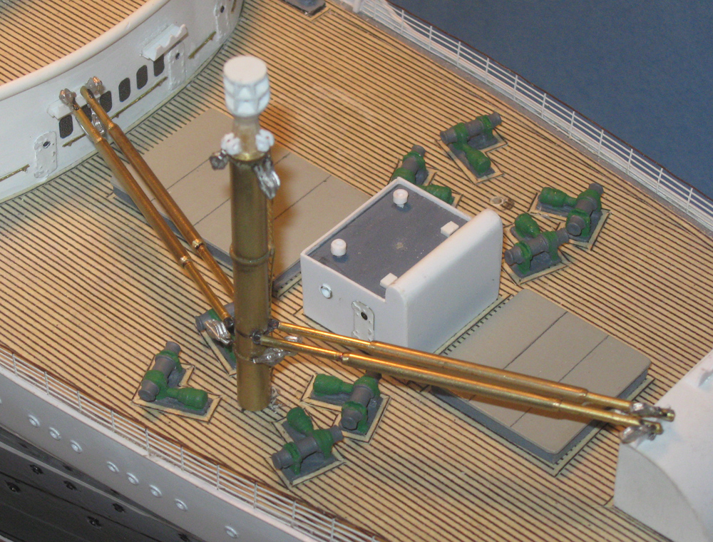
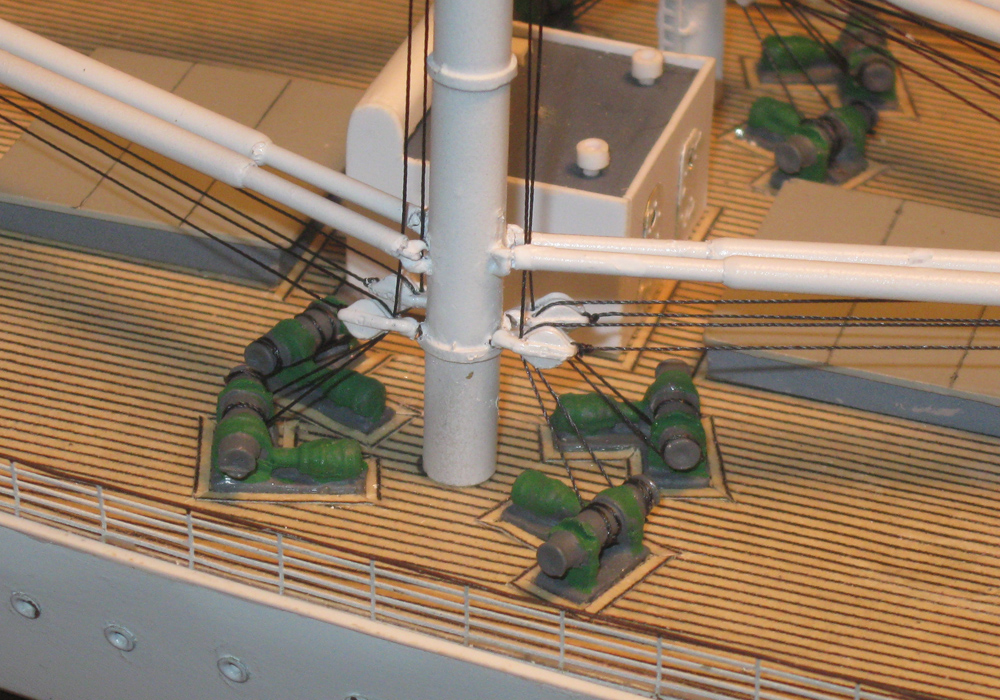
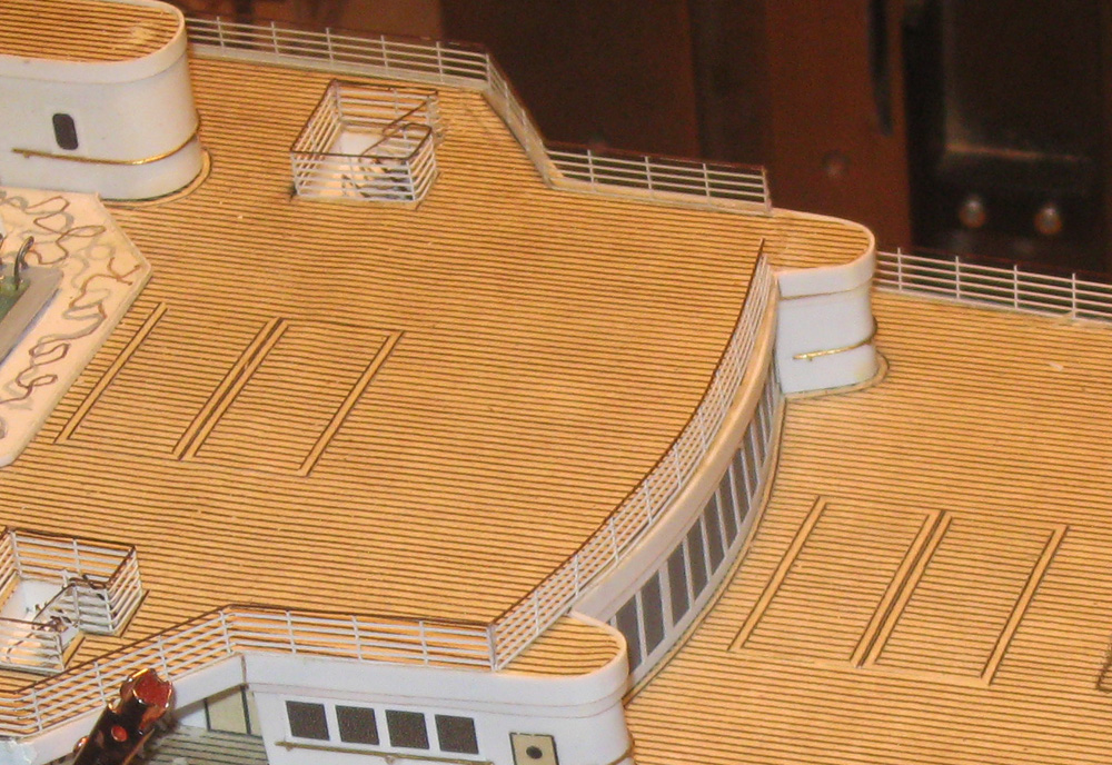
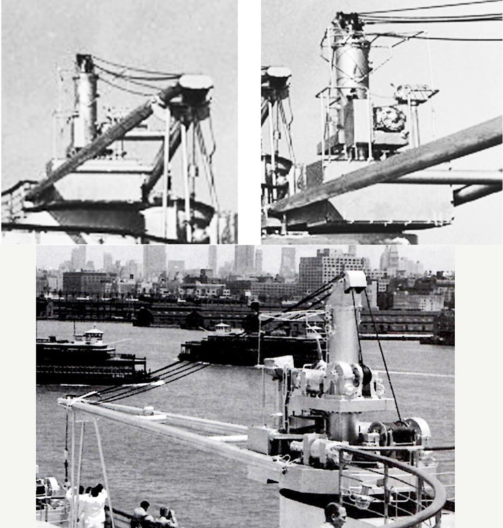
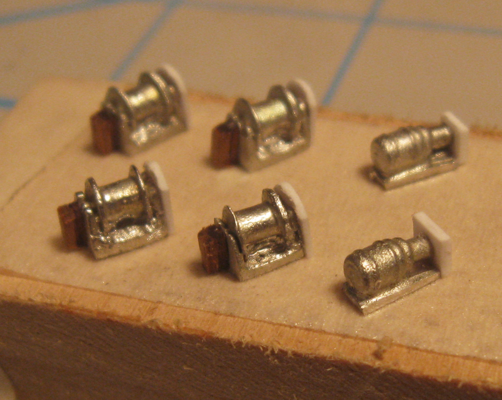
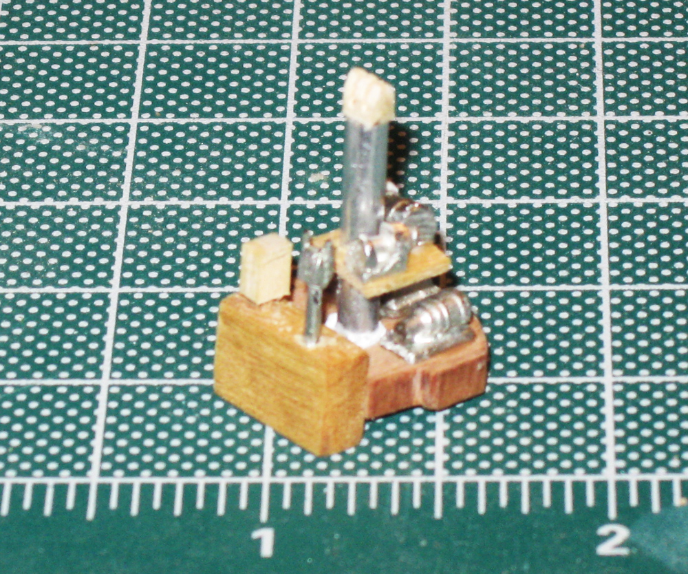
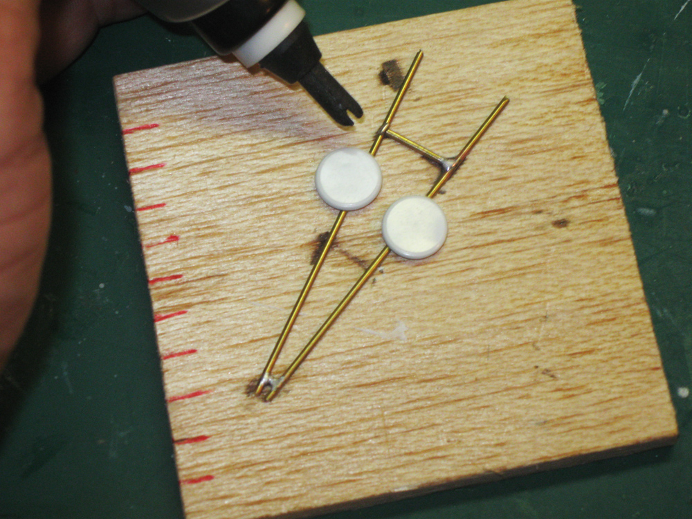
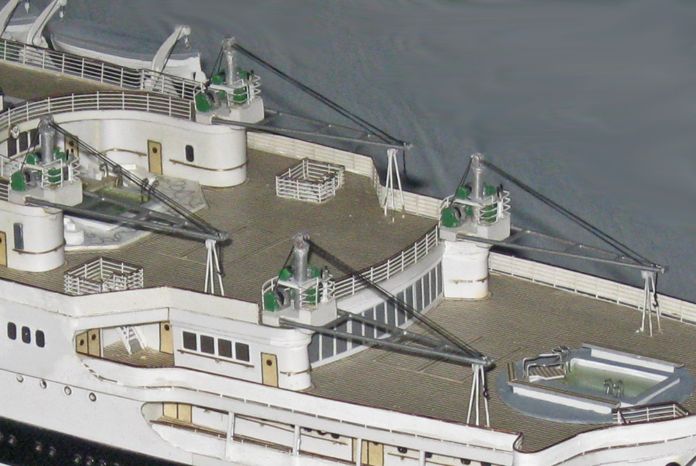
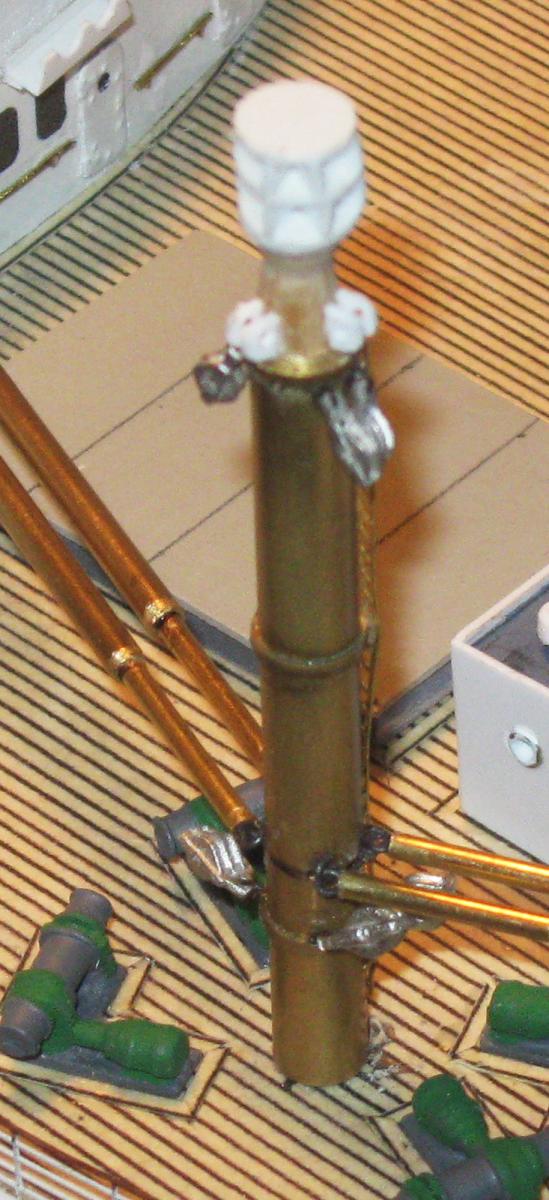
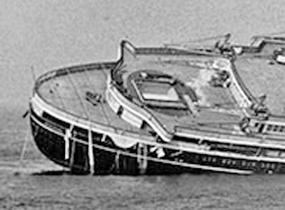
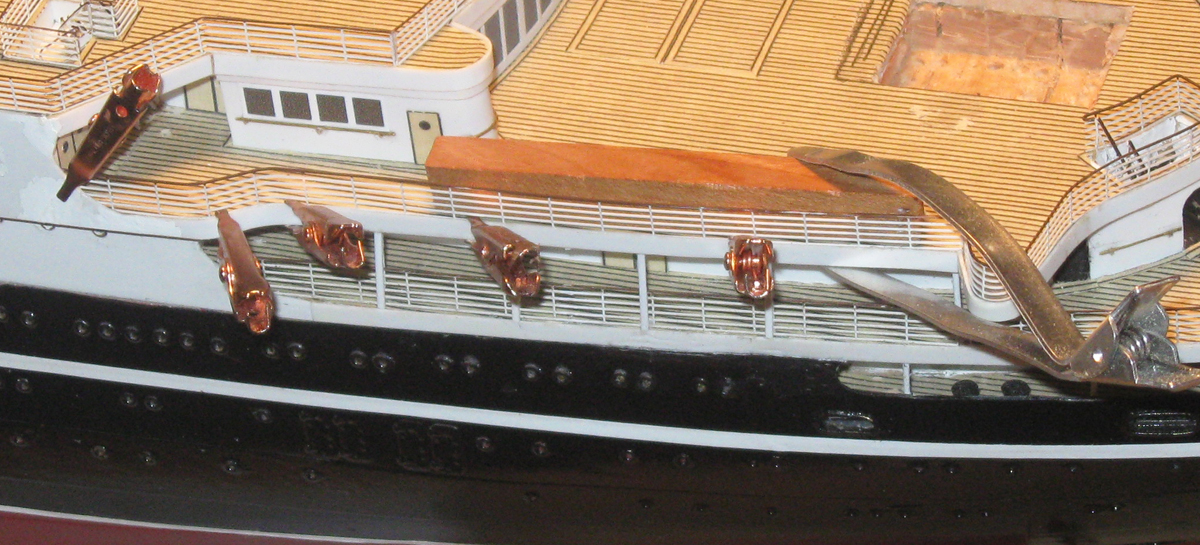
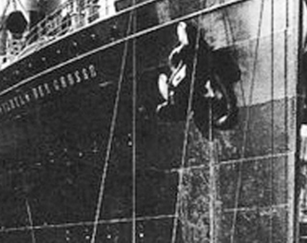
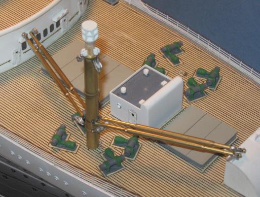
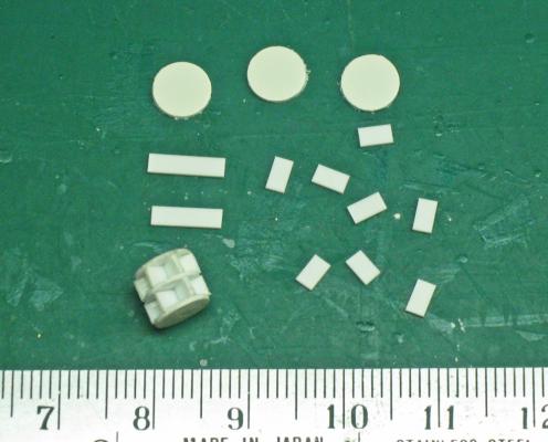
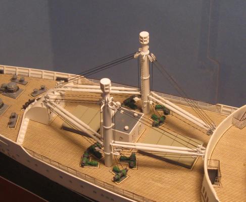
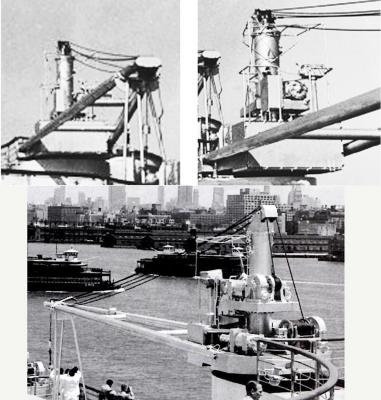
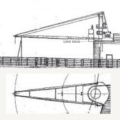
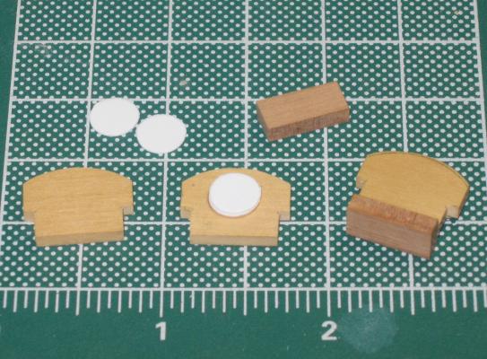
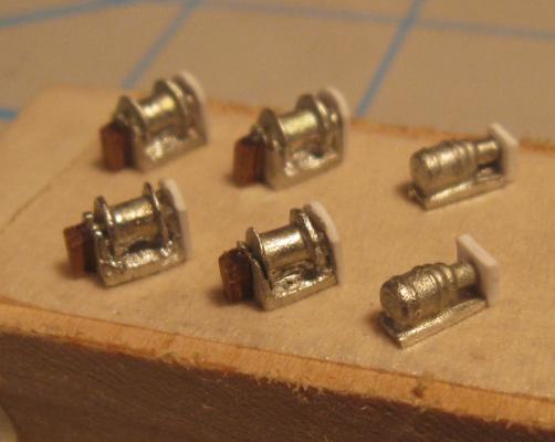
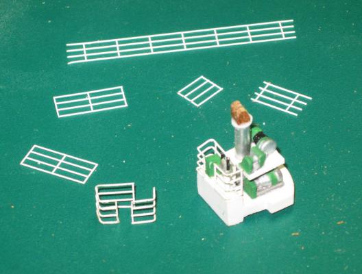
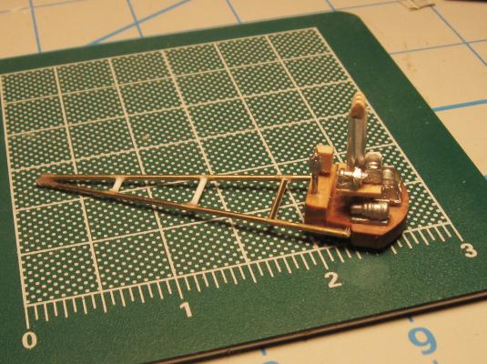
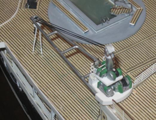
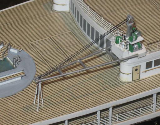
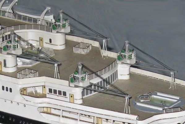
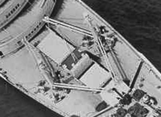
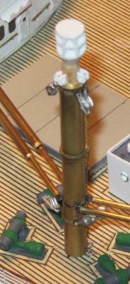
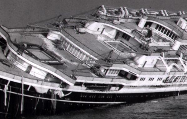
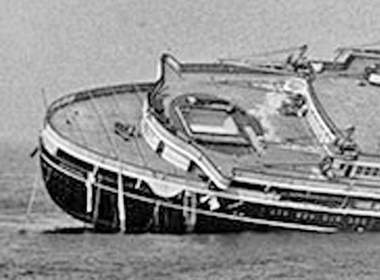
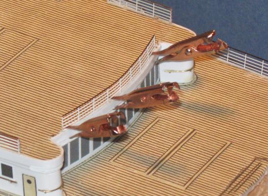
Build Log 13 - Cargo cranes Thanks to all who looked in, and for the compliments that I am not sure I deserve. During construction it felt like I was just muddling through, taking shortcuts that a truly dedicated modeler would avoid. This is the curse of the commissioned model – it has to get done without spending the rest of my life on it. Glad you liked the results, though. Next to be detailed was the cargo deck at the bow. This area contains two deck houses which are mostly companionways and for ventilation; two raised cargo hatches with multi-part covers; and two cargo cranes with four booms and four corresponding winches for the lifting cables. Here is how it looks on the deck plans: Photos of the area and the cranes are surprisingly scarce. With several upper decks looking over the working area I expected to find many photos, as I have seen with other ships. In fact, I found none of any detail or resolution from that angle. This is the best that I found, taken from above during the sinking, so I just went with what I could figure out. The deck houses are basswood sheathed with plastic, the portholes are my usual tiny grommets, and the watertight doors are photoetched aftermarket items. The raised cargo hatches are simple wooden platforms topped with plastic sheet. The hatch seams are scribed into the plastic after painting. The eight winches are Scott style and are cleaned up and detailed Bluejacket castings. All of the structures and fittings got margin plank strips in the usual way. These are the best photos that I could find of the cranes themselves and the cargo booms. Not a great deal of detail, but I puzzled out what I could and made educated guesses for the rest. Based on the number of cables running from the pulleys it looks like the cargo masts are fitted with a single block near the top that connects to a single block on the upper end of the boom. A similar single block is under the end of the boom, whose cable runs below the boom to a block on the mast near the deck. Here is the result. The booms were built up from brass rod slid through a sleeve of brass tube. Holes were drilled in the rods near the outer ends for the twisted wire strops of the cargo blocks, also Bluejacket castings. The booms attach to the mast with a pair of linked eyebolts that allow movement in all directions. The mast is a brass tube with a wooden dowel through it. This allowed me to insert a sturdy brass rod in the bottom to secure it to the deck, and to taper the upper end as seen in the photos. Three narrow brass bands were sliced off and attached to the mast tube. These support the photoetched ladder that you can just see mounted on the inner side of the mast. Plastic support lugs were shaped and attached as seen in the photos, although I do not know what their use was. Four single blocks were installed at the top and four double blocks at the bottom. The entire structure was topped with a complicated cap which may have some ventilation purpose, or maybe not. It was pieced together with three discs punched out from plastic sheet and twelve pieces of styrene strip, six in each layer. The masts and booms were primed and painted gloss white before being installed in the center of the crowd of deck winches. Cable of 0.008 polished threads were run through the pulley blocks and around the barrels of the winch heads. Cradles for the booms were made up from “L” angle strips of styrene with hollows for the tips, then installed on top of the curved deck house and the forward bulwark of the Upper Deck house. The cables were run loosely until the booms were secured in the cradles, then everything was tightened and trimmed. Given the lack of photos, I’m not completely sure that all the details are correct, but I believe that they are as close as reasonably possible. At the stern the cargo hatches are smaller and flush with the decks. Their locations and sizes are shown on the plans but do not show up on any of the photos that I found. So I made them simply by running strips of margin plank with mitered corners to define the perimeters of the hatch covers. No need to fill the centers since the eye cannot resolve such small changes in height. The cranes for these hatches are complicated assemblies, but very prominent features, so I could not skimp on them. They are made up from a wide base with a vertical cylindrical post that supports a second smaller platform. A winch and electric motor on the base raise the “A” frame arm, while a smaller winch and motor control the lifting cable and hook. At the front of the base is a platform for the winch controls and an electric panel box. Here are the two views from the plans which were used to determine the heights and sizes for the various elements of the crane. The base was made up from hardwood pieces with two discs of plastic to raise the base above the lip of the deck perimeter. The winches and electric motors were made up from various castings that were cut apart, trimmed and refined before small plastic and wood elements were added to match what I thought I saw in the photos. A length of aluminum tube was fitted into the base to make the vertical post, and a platform of thin hardwood was drilled and cut to slide down it. The winches and motors were added, as was the winch control, another Bluejacket casting. The electrical box was a tiny bit of wood, as was the fitting that housed to the pulleys at the top of the post. Sorry that this is not a better photo, but I must have been too busy building the crane to check the focus. The base and platforms were painted white, as were the railings, while the post, the motors and winches were silver with green and black details. The lifting arms are made of brass rods with two cross-members soldered between them to make a strong unit. Two other cross members were made up from plastic rod since they would not be under any stress. A tripod support, as seen in the photos, was made up from brass wires soldered to a bit of brass strip and painted white. Cables were run from the winches and a hook hung from the business end. The final piece was a curved cover for the pulley sheaves at the top of the post. Here is this one finished and installed as seen from the other angle. And here are the four as they look on the completed model. Not too many segments left. The end is in sight. Dan


- 108 replies
-
- 21
-
-
- andrea doria
- ocean liner
- (and 1 more)
-
Hi Nils - You asked about figures for your model. I did a quick Google search for "1/144 scale figures" and got a bunch of hits. Preiser makes figures that scale both painted and unpainted. They are available from a number of hobby sites in Europe, mostly England, but I found one in Germany. Prices seem to be around 10 Euros for 18 unpainted figures or 6 painted ones. I know that I paid a good deal more for them here in the USA Hope that helps Dan
- 2,625 replies
-
- 4
-
-
- kaiser wilhelm der grosse
- passenger steamer
- (and 1 more)
-
Nils - I did a quick Google search for "1/144 scale figures" and got a bunch of hits. Preiser makes figures that scale both painted and unpainted. They are available from a number of hobby sites in Europe, mostly England, but I found one in Germany. Prices seem to be around 10 Euros for 18 unpainted figures or 6 painted ones. I know that I paid a good deal more for them here in the USA Hope that helps I'll also post this on your KWdG log to be sure you get it. Dan
- 108 replies
-
- 5
-
-
- andrea doria
- ocean liner
- (and 1 more)
-
Hi all - Thanks for the likes and compliments, as always. Nils - they are 1/200 or 1/192 (1/16"), and they are not that great for their price. I don't think I have a line on 1/144 scale figures. I'll check some of my sources and get back to you if I find any. Dan
- 108 replies
-
- 5
-
-
- andrea doria
- ocean liner
- (and 1 more)
-
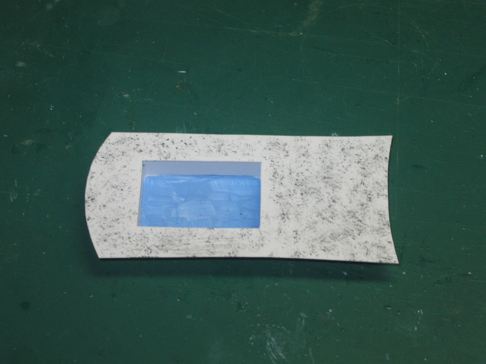
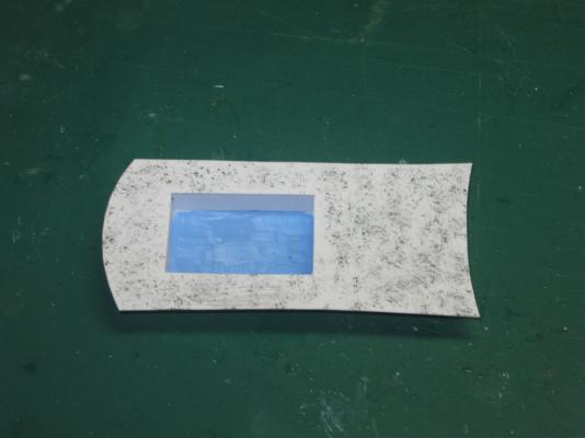
Hi Nils - Just coming back to this. AOL is having some issues with my automatic email from MSW, so I'm a bit behind the curve. Very pretty work, as usual, since I last stopped by. I completely agree that you have hit on a clever solution to the 'glassing' problem. The portholes look totally realistic on the test piece. As for the color separation line, here is a technique that has not been mentioned, but worked for me in a similar situation on an irregular surface: Instead of using just tape, paint a layer of rubber cement over the line. Cover the rivet heads and everything else with a perceptable thickness of rubber. You may need a few coats to get that thick. Once it has hardened, use a metal straightedge to guide a sharp blade along the line. Do it a few times to make sure you have cut through to the hull. Then just peel off the unwanted side of the line. If there is some that sticks where you don't want it, rub it with a gum eraser and it will come right up. Mask over the rubber with tape and paint as usual. Maybe that will work for you. Best of success. Getting that line crisp and clean is a major challenge, but you have repeatedly shown that your skills are up to the task. Dan
- 2,625 replies
-
- 3
-
-
- kaiser wilhelm der grosse
- passenger steamer
- (and 1 more)
-
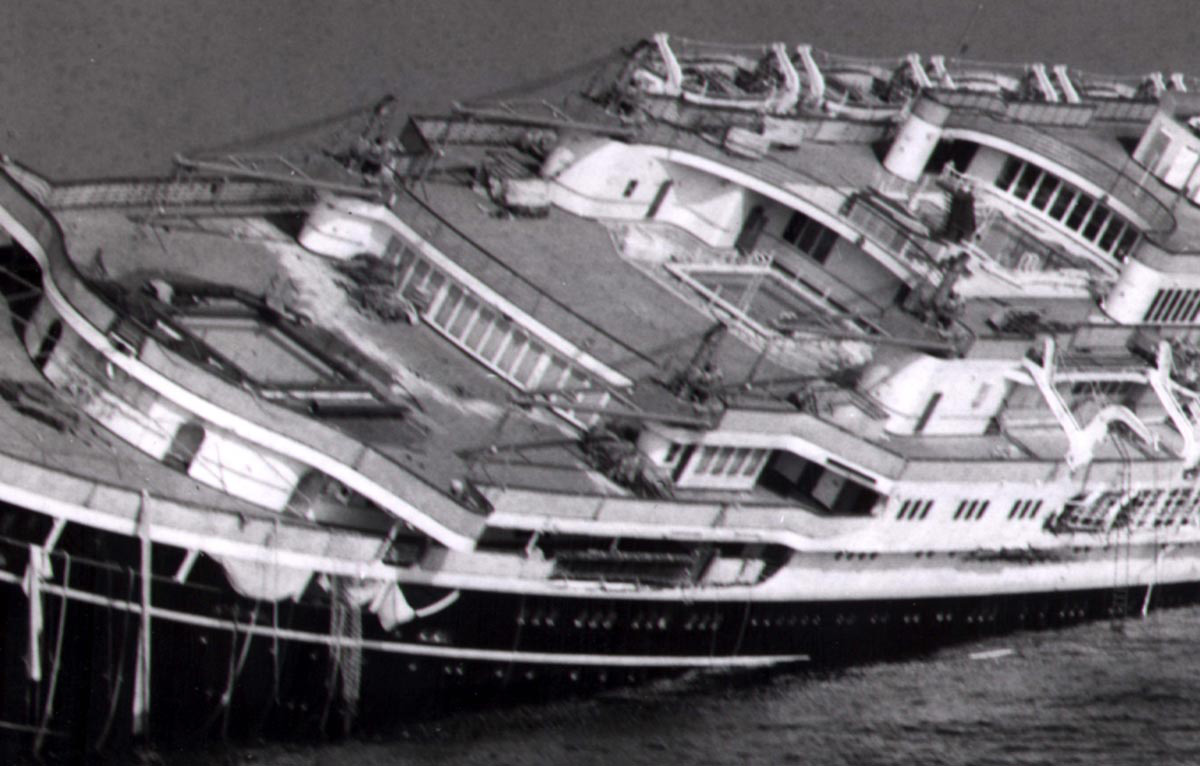
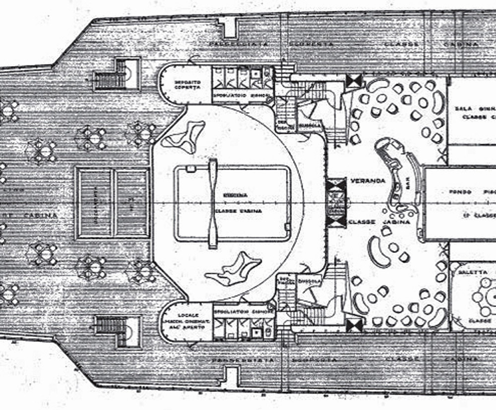
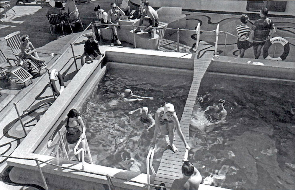
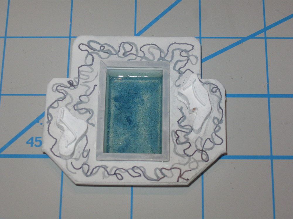
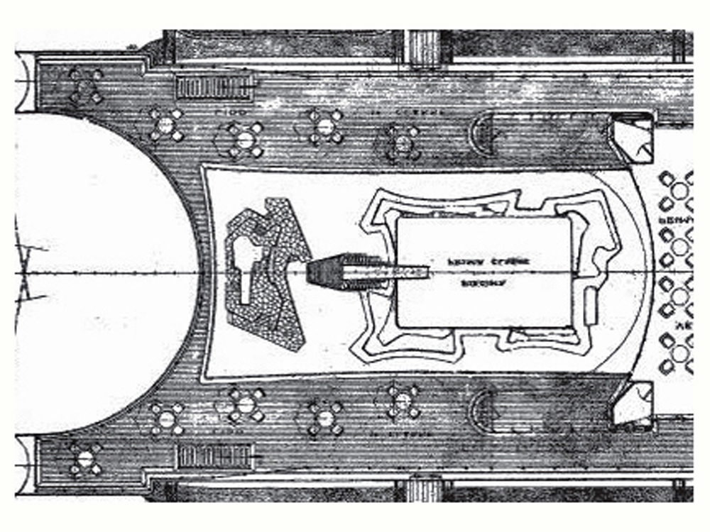
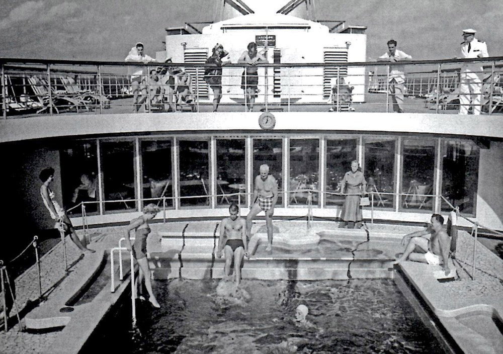
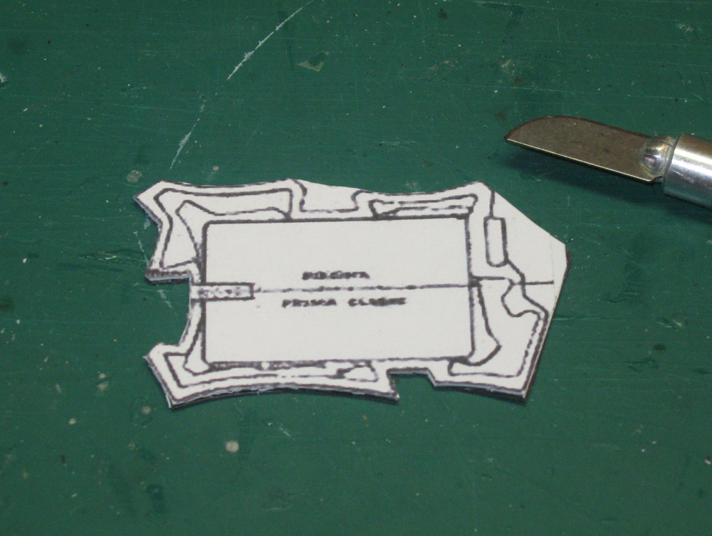
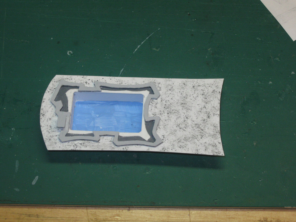
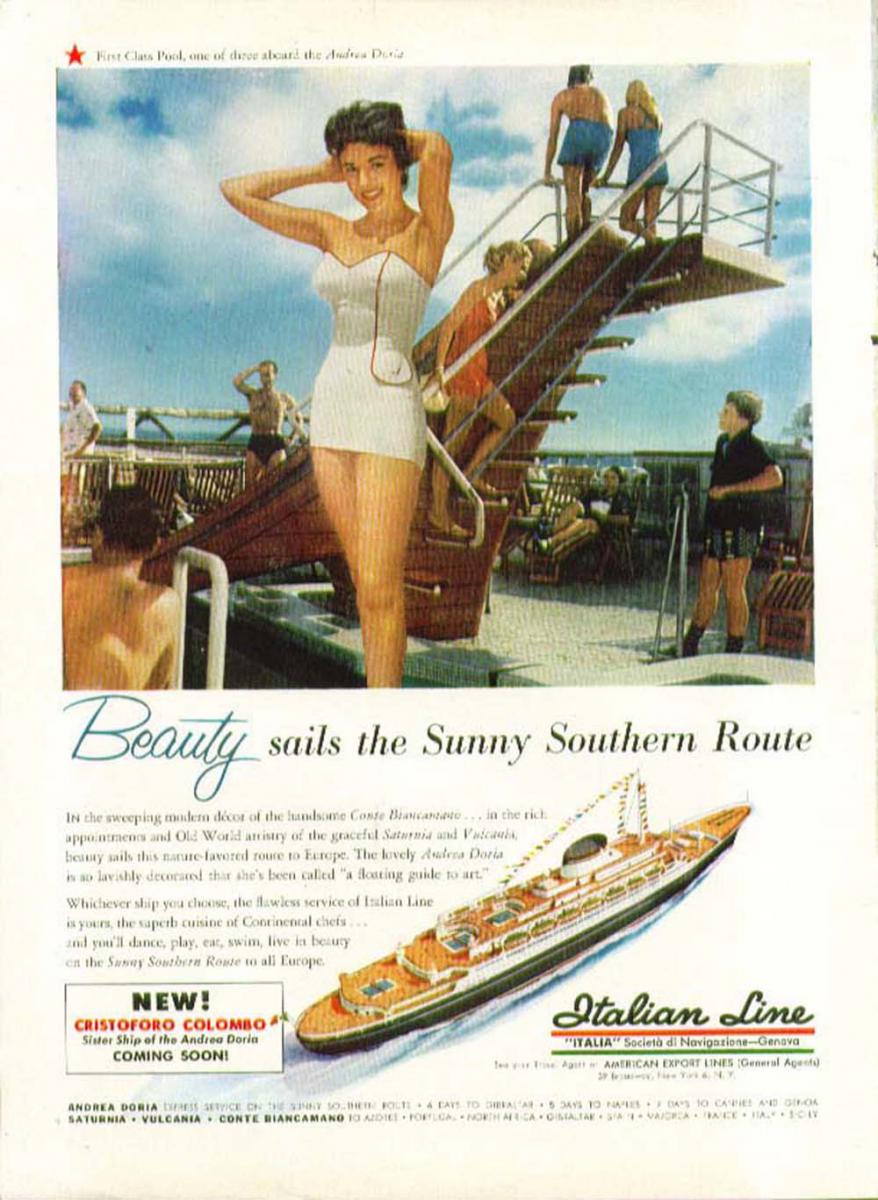
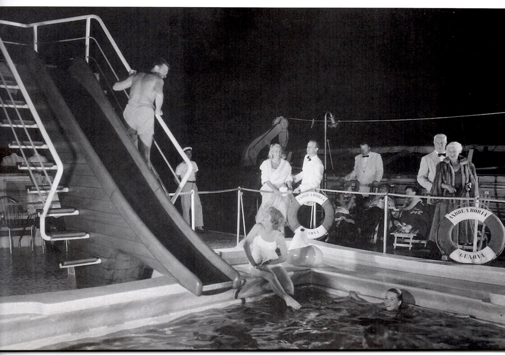
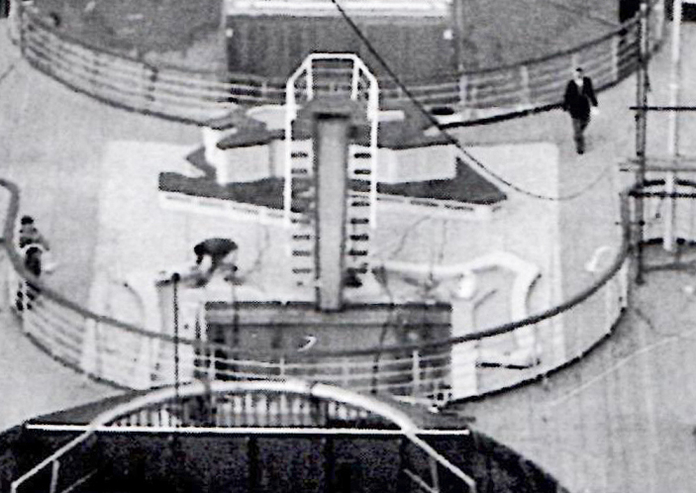
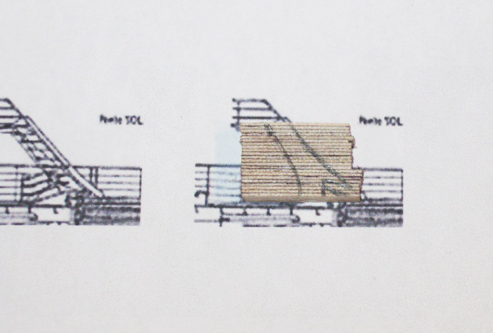
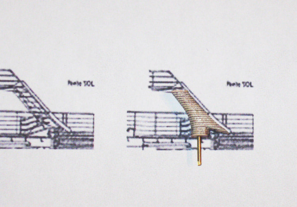
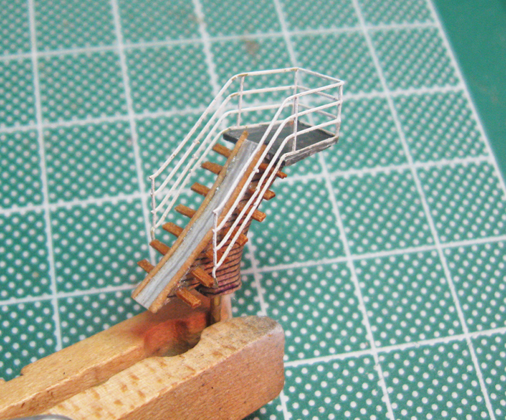
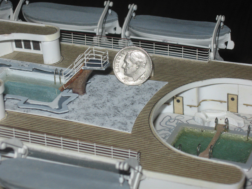
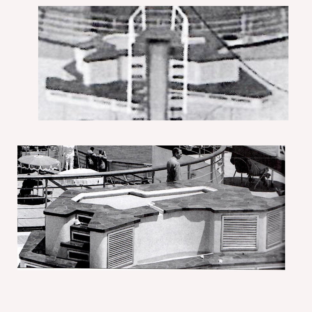
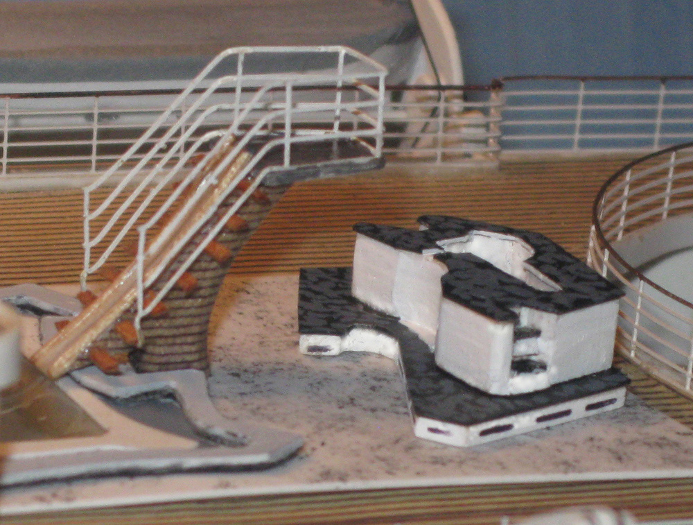
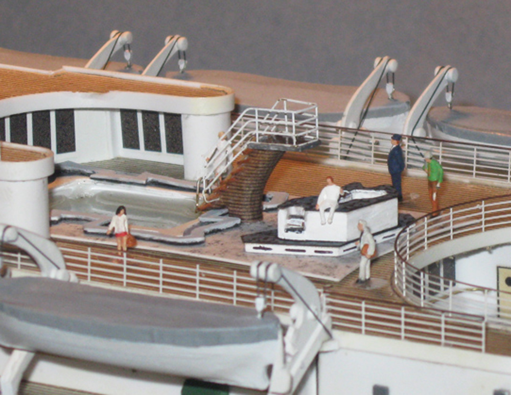
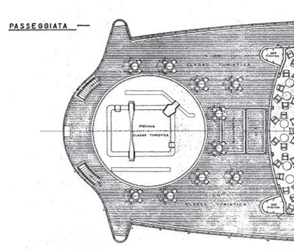
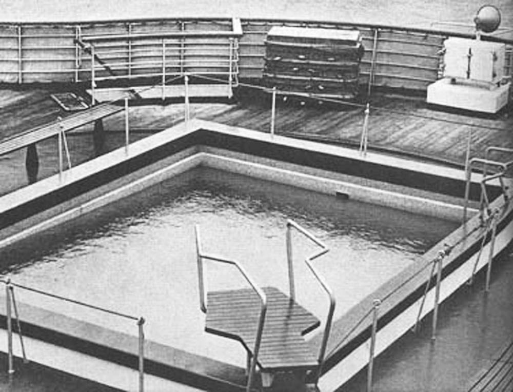
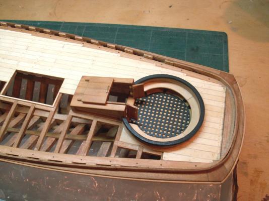
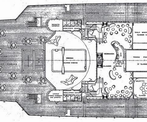
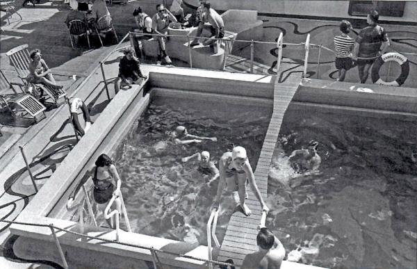
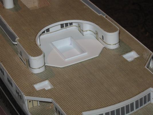
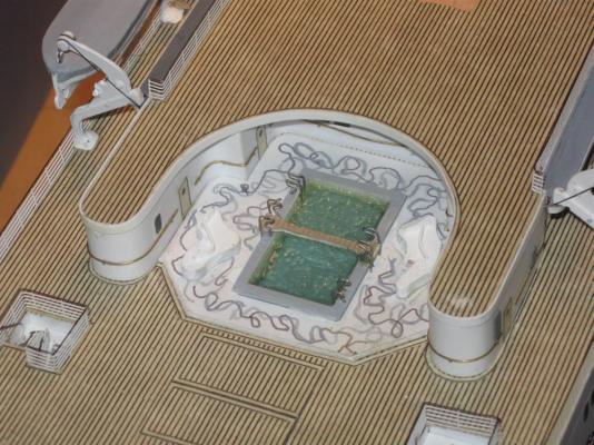
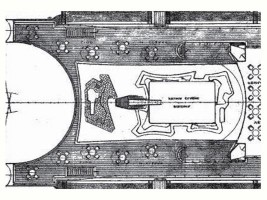
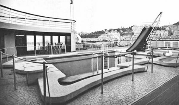
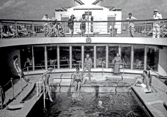
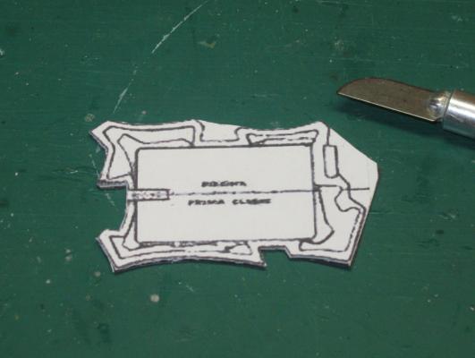
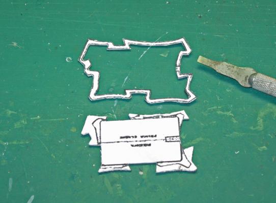
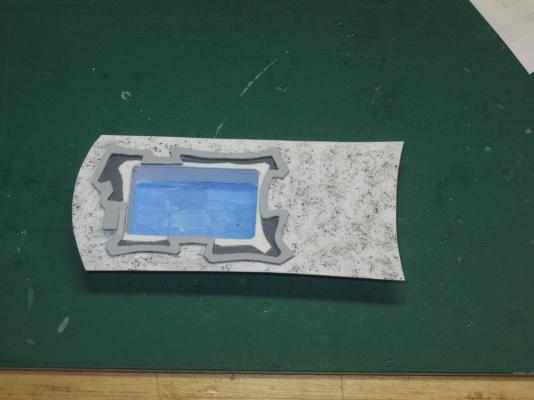
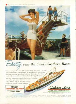
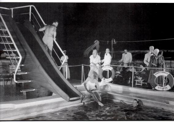
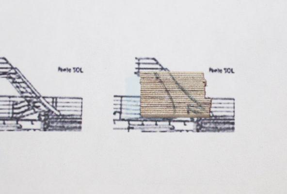
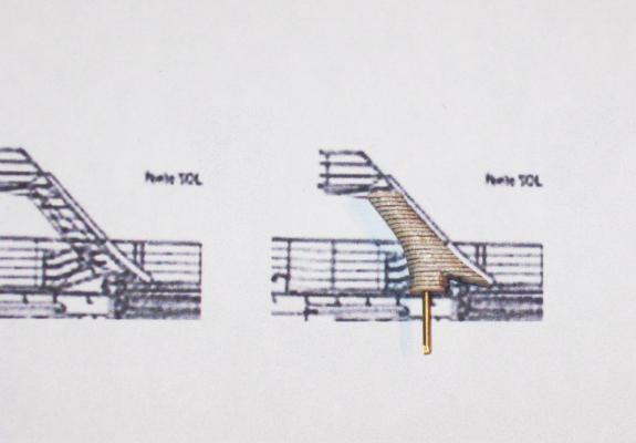
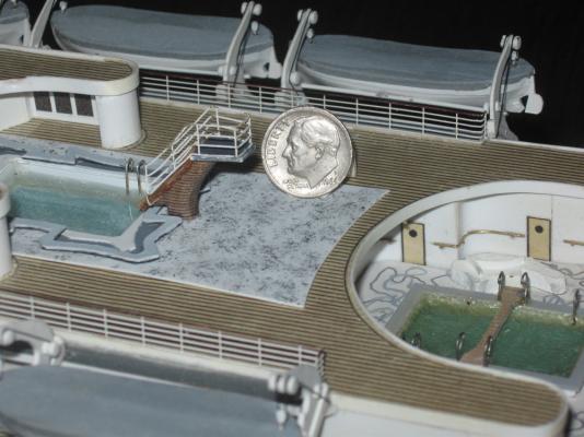
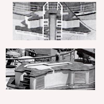
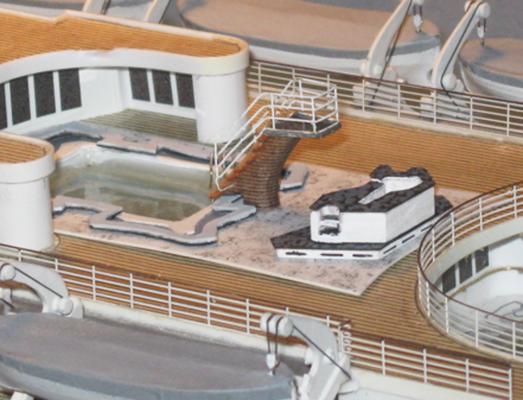
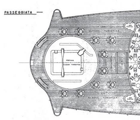
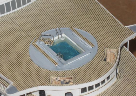
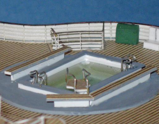
Build Log 12 – 2nd and 1st Class Pools Good to see so many of you at the NRG conference last weekend. There were lots of excellent models and interesting talks. The tabletop demonstrations were done by master modelers, and I learned some new tricks to try on my own work. Here is the next segment of the build log. It is heavy on photos and light on text, so to get the full effect you can click on any of the photos and it should open in a larger and more detailed format. You can scroll from there through them without the text if you want. After finishing the 3d Class pool I moved onward and upward to the 2nd and 1st Class pools. Here you can see them all together and the relationships between them and the rest of the ship. The 2nd Class pool is tucked between two arms of the Boat Deck house and below the overhang of the Lido Deck. On the plans it looks like this. The pool is rectangular with an hourglass shaped with something unidentified across it. The surround fills the space between the arms, with a wedge shaped aft end and two amoeba-like somethings on either side. Thanks to this and other photos I learned that the hourglass was a planked balance beam sort of thing which must have been fun to use in rough seas. The amoebas turned out to be seating units that looked to be made of some cast material. The surround was decorated with swirling lines in three shades. I did not find a color photo, so I ultimately went with a simple selection of light grey, medium grey and black. The pool tub was constructed as before, as was the surround. A paper template was made up to determine the fit between the deck houses and the plastic piece cut and fit to match. The hole for the pool was located and cut and the tub dropped in. The bottom of the pool tub was painted a light blue. I purposely left brush marks and areas of incomplete coverage which give the bottom some definition under the epoxy layers. The surround was given an overall coat of very light grey, with random squiggly lines of medium grey and black painted on. I did not have a complete look at the designs on the surround, so this is just an impression of what might have been. I carved the seats from 1/8” hardwood for seats 24 inches high, and added backs of 3/32” tall plastic in the style seen in the photo. I cannot swear that these seats are 100% accurate, but they are pretty close. The balance beam was cut from styrene and topped with decking. The handrails for the balance beam are taller than those for the ladders and face the other way. All were installed before a second layer of epoxy was poured. The assembly was installed and a margin plank fit around it. About a week later the top layer of epoxy started to get an ‘orange peel’ effect. I have no idea why this happened. I used the same product, Devcon 2-ton epoxy, in the same mixture as the other pools where this did not happen. It was too late to remove and replace the pool without causing major damage, so I tried to tone down the effect with a top layer of white glue, with only middling success. I could not try anything else because the pool was already full so I left it. The effect is not unpleasant, just different than the smooth surfaces of the other two pools. The 1st Class pool is the largest and most complicated of the three, of course. The plans show that it fits between two arms that extend aft from the Lido Deck house and under the overhang of the Sun Deck. The construction of those arms are not clear, but they are not drawn as if they are solid. The surround flares at its aft end, while the pool has an intricate structure around it, with two unidentified items toward the aft end of the surround. The photos clear up most of this. There are more of them for this pool than the others. I guess the first class passengers had access to more cameras. This one turned out to be the most useful. You can see that the pool is even more complicated than I first thought. The structure around the pool is not only intricate, but has multiple levels to it. Perhaps as contrast, the ladders have simple rectangular handrails. The surround has a surface composed of what look like small random tiles, while there is a large slide at the aft end. The other structure behind the slide is still a mystery. The arms of the deck house are, indeed, hollow, and are basically windbreaks made of large windows. Looking in the other direction I decided that there were four levels to the pool seating. Each seems to be about 6 inches thick. The ladder that the woman is on sits on a raised lip which goes completely around the pool. Behind its irregular shape in some places the level goes down to the level of the surface of the surround. Behind and around everything is a level two steps up. The final level is only the small raised platform between the woman on the ladder and the seated man. Construction began as usual, but this time the pool tub was attached flush under the hole in the surround. I could not make those small irregular tiles, but dark grey stippling seemed to give approximately the same look from a distance. The shapes of the seating levels were taken from the plans. Here a copy of the plan has been glued to a sheet of the proper thickness and the outside of the second level is being trimmed away with a sharp blade. Then the inside of the level was chiseled out with a narrow blade, separating the piece. The plan was removed with a few drops of mineral spirits which does not affect the plastic. The same process was used for the first level before they were assembled on the surround. The zero level was painted a dark grey, the first level left white, and the second level painted a light grey, as was the fourth level, the platform. Now I turned to the slide. I knew from my review of the photos and brochures that this was one of the high points of the ship’s details. Here it is in a color advertisement. Once I pulled my eyes away from the pretty woman I could see that it was not going to be a simple thing to build. The main part was made of wood, with the look of a high-heeled shoe. The upper platform and the steps were cantilevered out from it. The handrails were bent in several directions with minimal attachment points. This shot confirmed all of that, and added that the ‘shoe’ base was actually made up of wooden lifts with dark lines between them. Note the life preservers, which will come up later on, and the woman on the right in her mink coat, who will not. From above, in the photo of the funnel, the slide appears as well. Here the shape of the upper platform is seen as being wider at the step edge than at the back. The absence of any risers between the steps makes for a see-through effect. Behind the slide is that other structure, whose purpose I still could not make out . I cropped and printed out in actual size the small portion of the profile plan that included the side view of the slide. A stack of 22 layers of veneer was glued up with black glue and the shoe shape of the base was drawn on the stack. The stack was cut, carved, and sanded to shape. A brass pin was fit into a hole in this base. The upper platform was cut and added, then the slide, which was made from two side pieces of wood and a middle of thin plastic. The steps were cut from a strip of boxwood and glued to the base. I thought about supporting them with individual wires but the glue seemed to be quite strong enough for such tiny pieces. I used medium cyano initially, to give the parts a quick, strong bond. But cyano can be brittle, so the joints were reinforced with a painted coat of white glue, which remains flexible, to cushion the cyano from shocks. The railing is photoetched 3-bar railing. It was bent to fit around the upper platform then skewed down the line of the steps. One vertical post on each side was clipped off while a long leg was left on the lowest rail. This leg was bent under the second step and secured into the base. The wood was given a finish of cherry stain to match the tone of the brochure image. Here are the pool and slide temporarily installed with FDR looking on. Another photo finally gave me the answer to the identity of the structure behind the slide. It turns out to be some sort of spa or hot tub! I can’t think of anything else that would have steps up into it with an overflow channel. The lower level is about 1 foot high, the upper another 3 feet tall, each with a thin top of dark stone tiles. The layers were made of hardwood cut to shape and painted. The stone tiles were made from thin black plastic mottled with dark grey spots. The hot tub itself was carved out with drill bitts and grinding burrs. A drop of epoxy filled the hot tub and everything was permanently installed. A margin plank at the aft end of the surround finished off the pool. I have to say that it does look inviting, but I just couldn’t get down there to use them. At least these Preiser figures can enjoy a quick dip or a long soak. Next up will be the large cargo cranes on the fore deck and the rotating ones on the ends of the arms of the Boat and Lido decks. I should have this out soon. Till then, be well. Dan


- 108 replies
-
- 19
-
-
- andrea doria
- ocean liner
- (and 1 more)
-
Outstanding work, Nils - Your strake edges are crisp, clean and straight. That's not easy with metal foil. You even have the rivet heads lining up at the intersections of the vertical columns and horizontal rows. No doubling or offset of the pattern. Congratulations. Coal hatches are a nice touch. Did you solder the hinges? Dan
- 2,625 replies
-
- 6
-
-
- kaiser wilhelm der grosse
- passenger steamer
- (and 1 more)
-
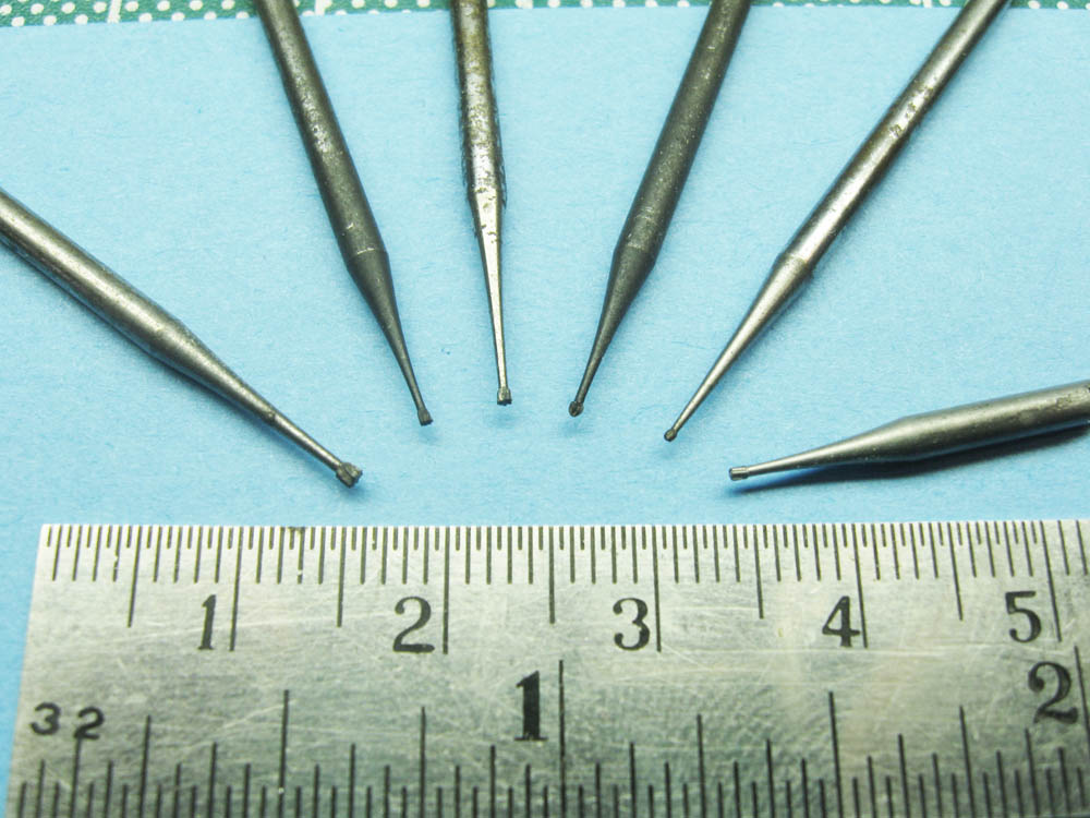
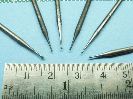
Hi Mark - Looking good. That stack of lifts for the longboat should work out well. Looking forward to your progress. For carving those really small letters, I have had some good success by using micro-bitts for the Dremel that I have accumulated over the years. Here is a photo of some of the smaller ones. The last on the right is from my dentist, who is a great source of tiny tools. Dan
-
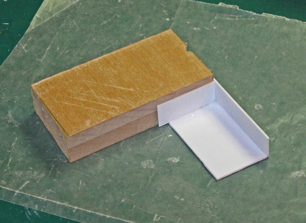
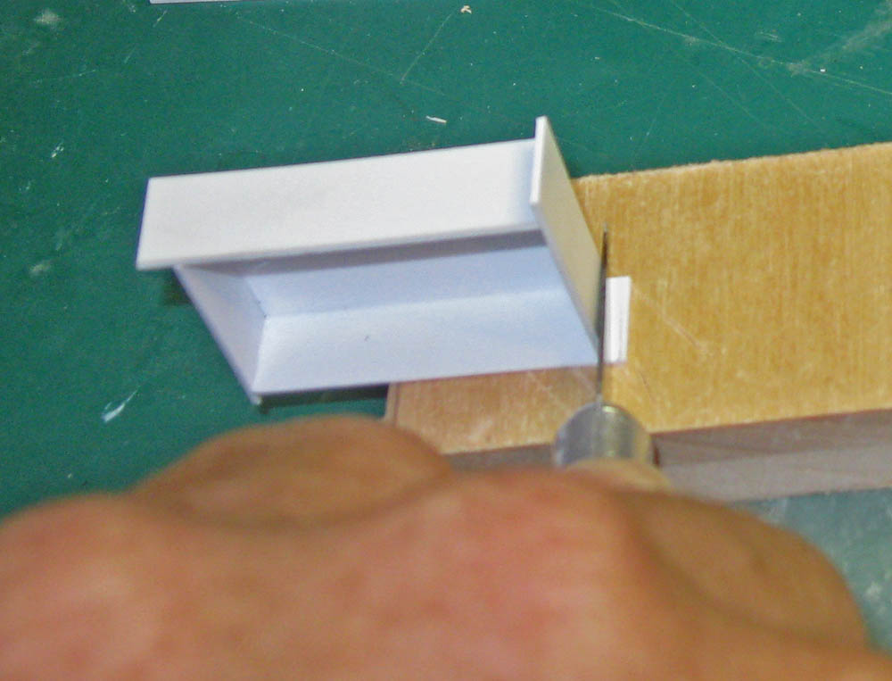
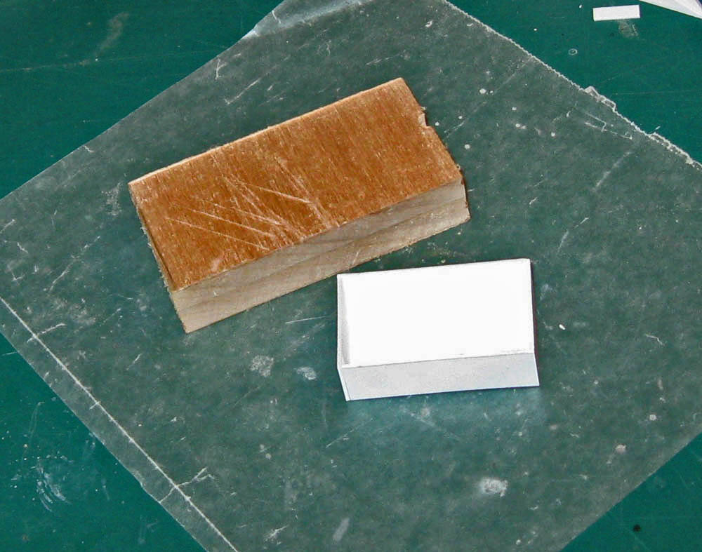
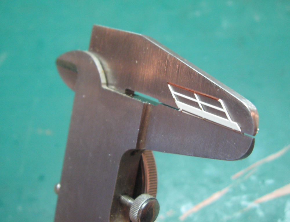
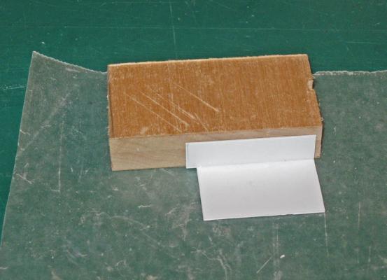
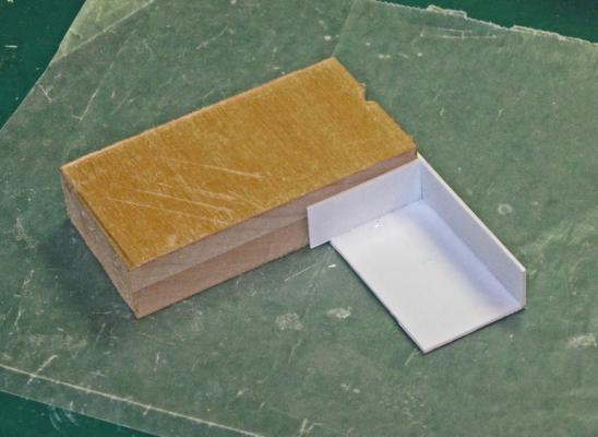
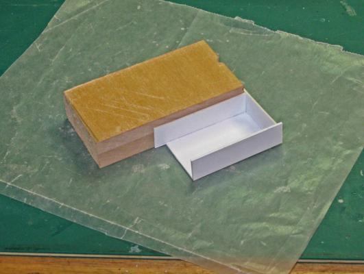
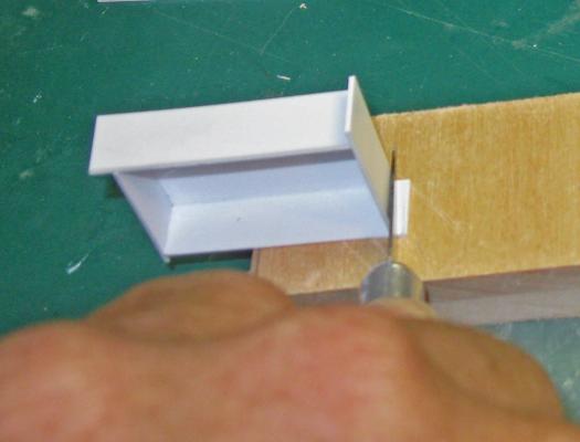
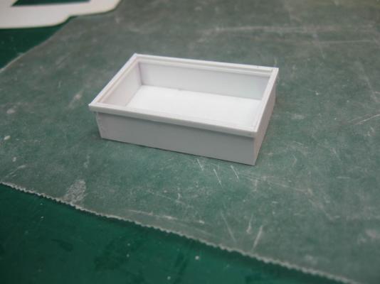
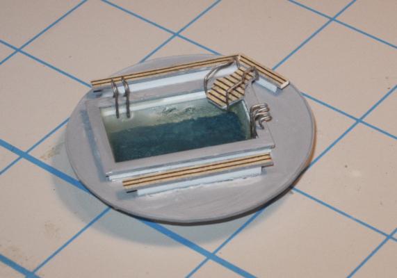
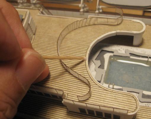
Build Log 11 - the 3rd Class pool Since you are reading this, the posting went through, which tells me that I can't put more than about 25 photos in any one post. So here is the rest of what would have been Log 10. It is heavy on photos and light on text, but short enough not to run up against any limits within the programming. In some of the photos in the last segment you can see the rough empty hole in the Promenade Deck which was carved to hold the 3rd class pool. This was the simplest of the three pools on the ship, and on the lowest deck, so it was the one I started with. Some deduction as to its appearance was required, as with many of the final details of the ship. Here is all that the plans provided. And here is the best of the overall photographs. No color photograph was located with enough detail to conclusively tell me what color the circular surround was. The best I could infer was a uniform grey/brown. I did locate a nice detail shot of the pool, which was my main guide for the construction. Note the stylish Italian design of the handrails of the ladders and around the diving platform. The lip of the pool and the surround seem to be made of small flat tiles, but I couldn’t be sure. In any event, I worked to get as close to this look as possible. All three pools began with the pool tub, made up from plastic. The base of the pool was cut according to the plans, but reduced by the thickness of the four sides. A strip of 0.020” styrene was cut from a sheet of stock that was long enough to make up all four sides and high enough to make a reasonably deep pool. Four lengths were cut, each one longer than the side of the pool that it would become. As should be clear by now, I don’t really follow the old rule about measuring and cutting. I find it better to work out a procedure so there is no measuring at all. Here is how it worked for the pool tubs: The first side was held against the base using a piece of scrapwood with square sides. One end of the side was carefully aligned with one end of the base, leaving the extra length of the side to go past the other end. Cyano was fed along the seam and allowed to dry. A piece of waxed paper was used to keep the piece from being glued to the work surface. The second side was held against the next edge of the base and against the first side using the same scrapwood to align it vertically. This was glued to the base and to the first side. The third side and the fourth sides were done in the same manner. With all four sides glued in place the extra tabs were cut off flush with the tub sides. And here is the completed tub. A thin strip was glued to the inner faces of the sides to represent the drain gutter seen in the photo. Another strip was added to the outside perimeter, set flush with the top of the sides. Its height set the distance that the pool sticks up above the tile surround. The circle of the surround was cut from thin sheet and a lip was glued to the perimeter. The hole for the pool tub was cut to fit snugly around the tub, so the thickness of the perimeter strip would keep the tub from sliding through. The strip also hid any tiny gaps. The tub was dropped into the surround and secured. A top lip was added and the surround and lip painted grey. The bottom of the pool was painted a Carribean light blue before a first layer of clear epoxy was poured for the water. The handrails for the ladders were bent up from wire, as was the railing around the diving platform. The platform and benches were given ‘wooden’ slats before the final epoxy pour locked the ladders in place. I tried to add metal rungs to the ladders, but that proved to be above and beyond my limits. The finished pool was loosely test fit in place in the deck to check its appearance. Once I was happy it was removed for safekeeping and was not secured until much later in the build. Here it is at that later stage. I took the photo from much the same angle as the initial photo that I relied on. I leave it to you to decide how close to an accurate representation I managed to come. Next time I continue with the larger and more complicated assemblies for the 2nd and 1st Class pools. Dan


- 108 replies
-
- 12
-
-
- andrea doria
- ocean liner
- (and 1 more)
-
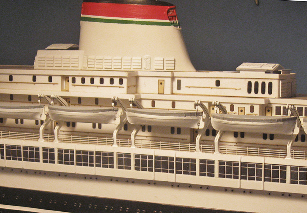
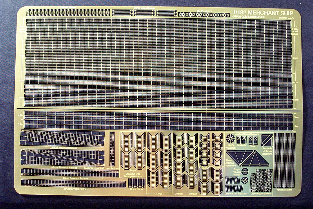
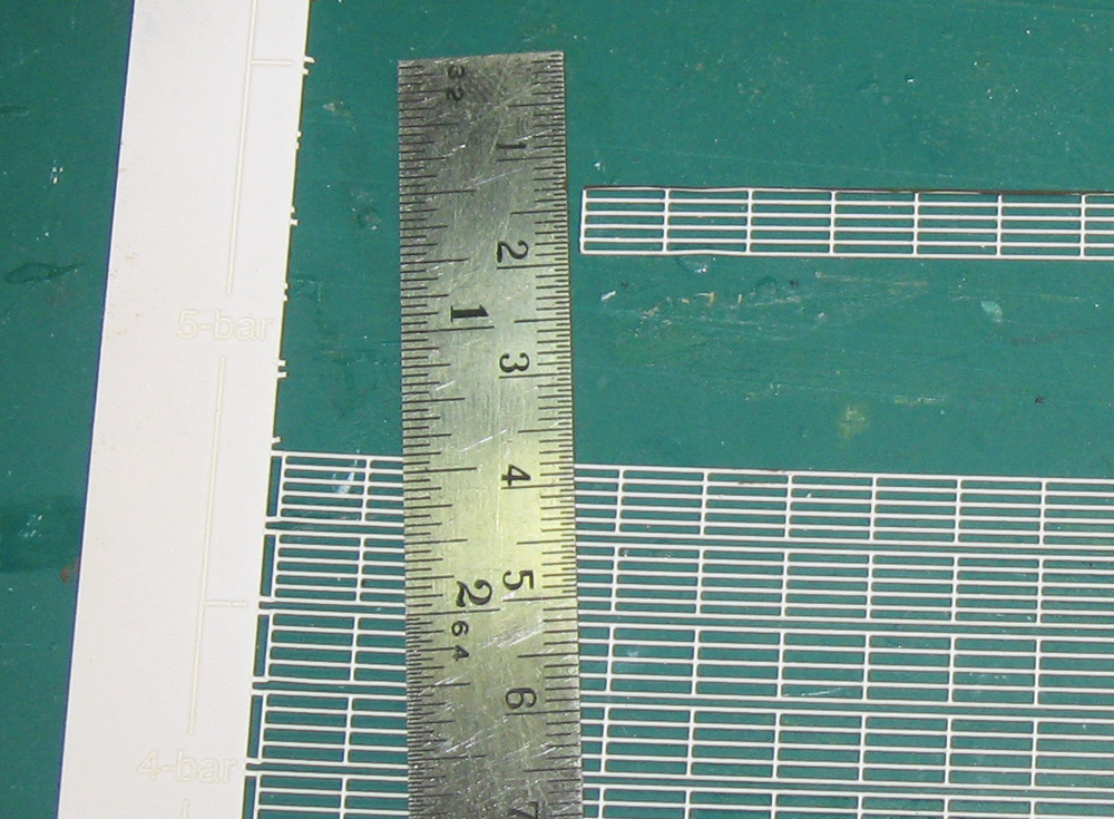
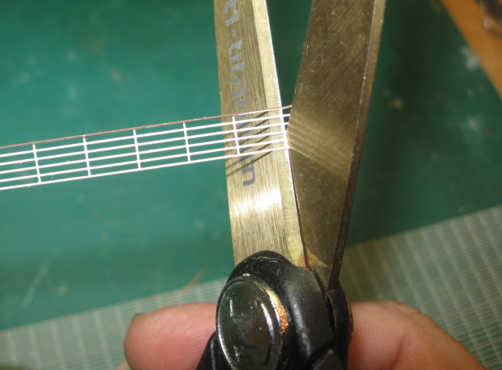
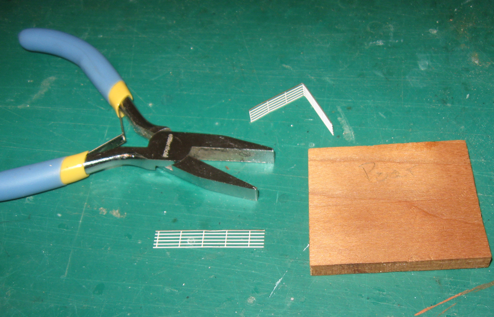
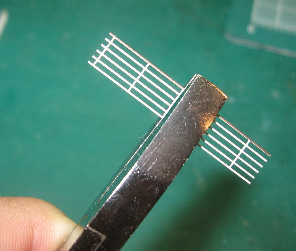
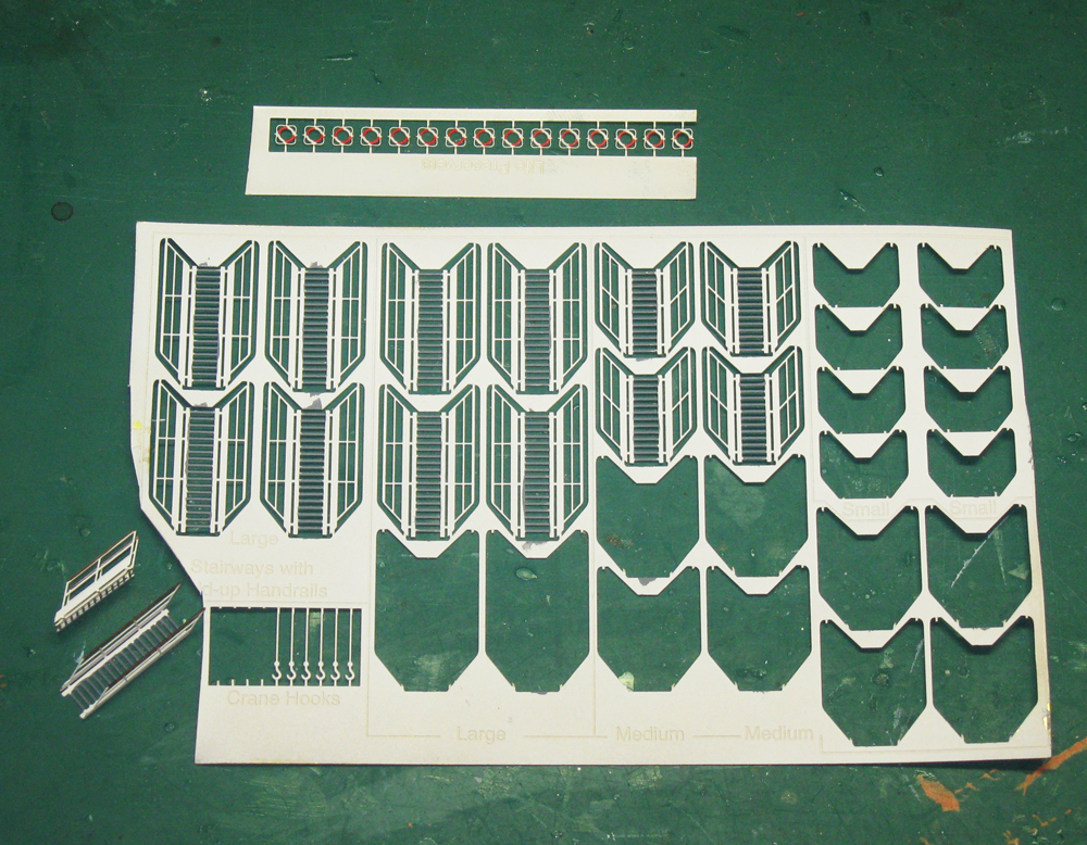
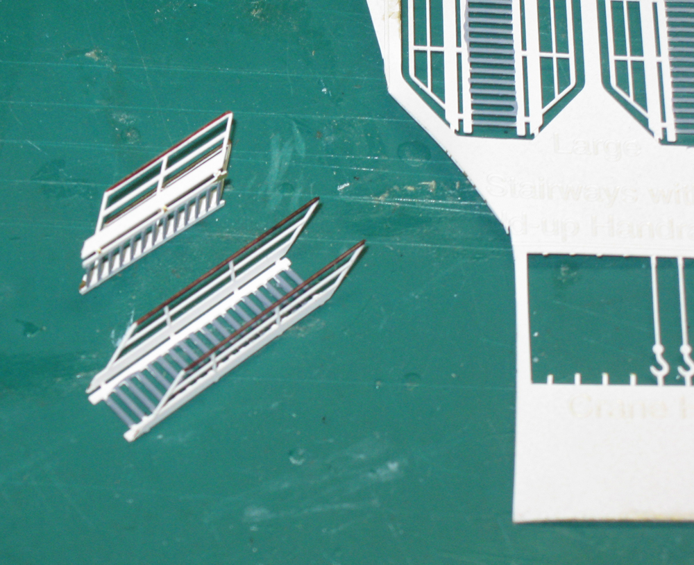
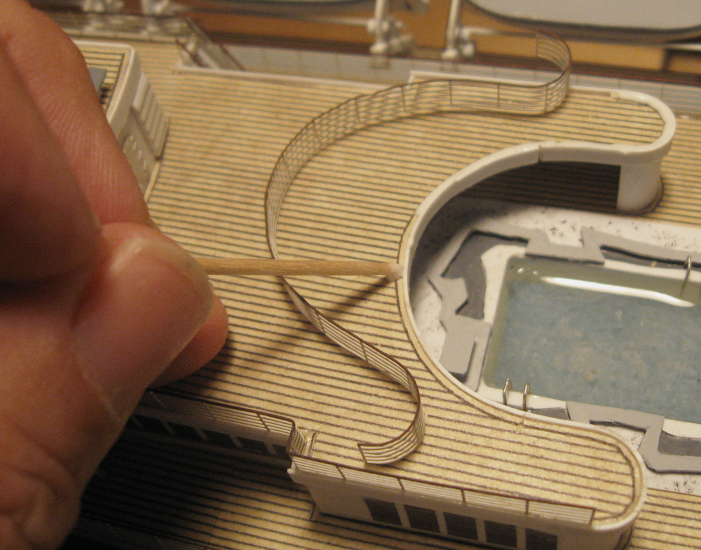
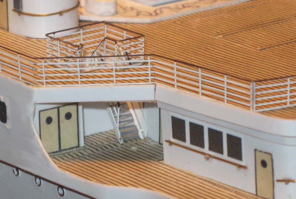
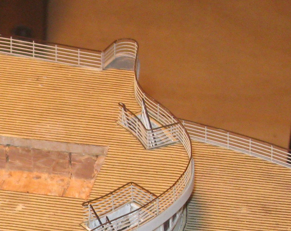
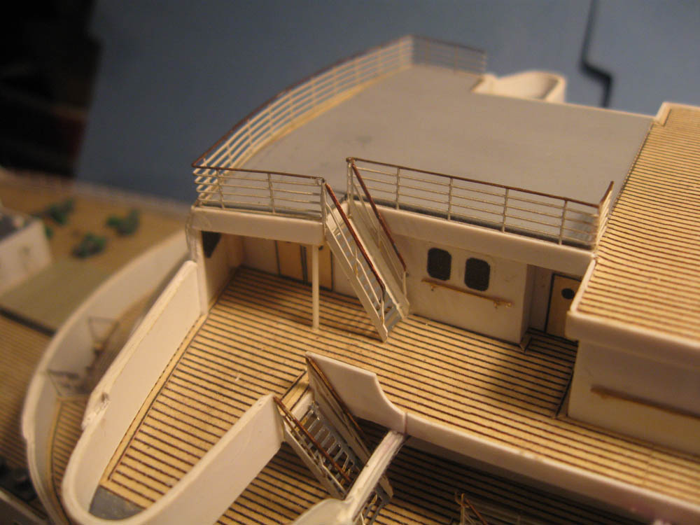
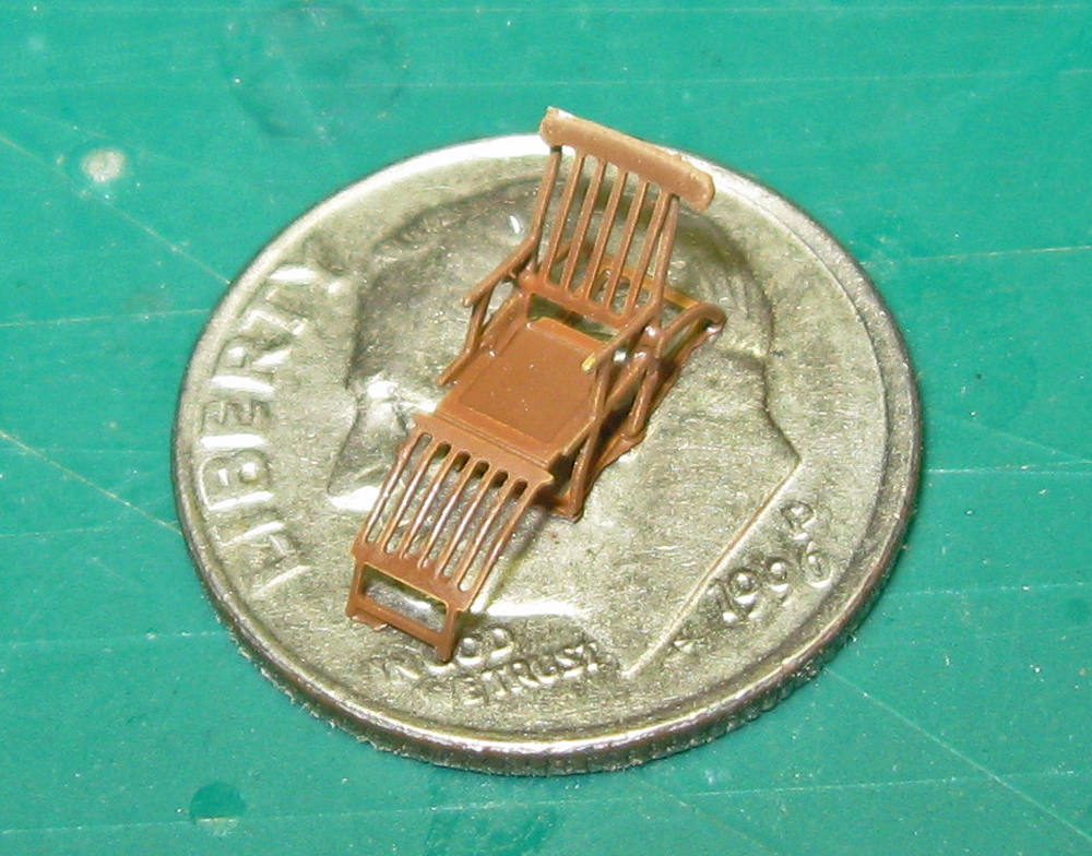
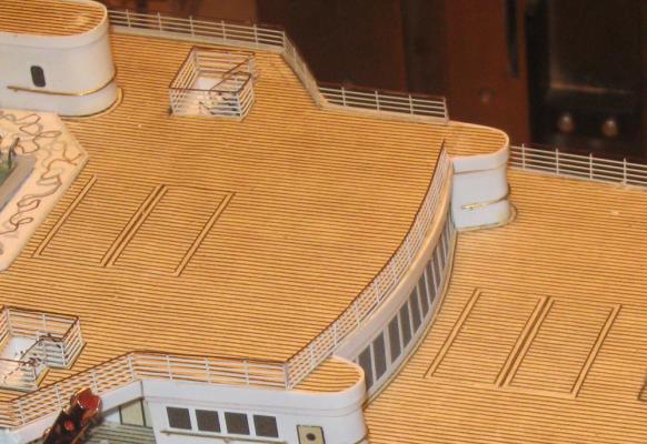
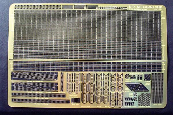
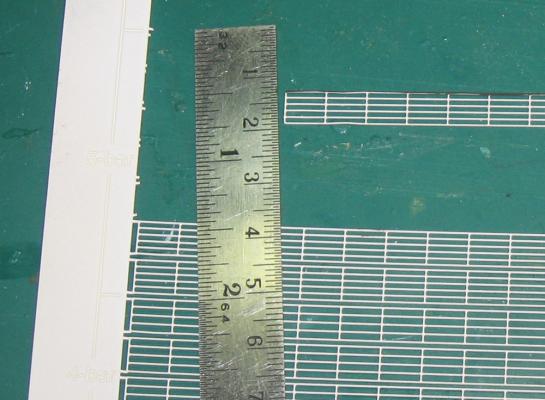
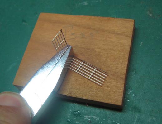
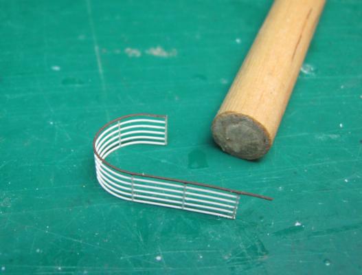
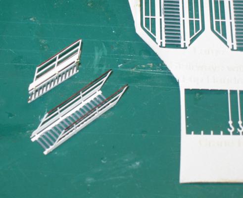
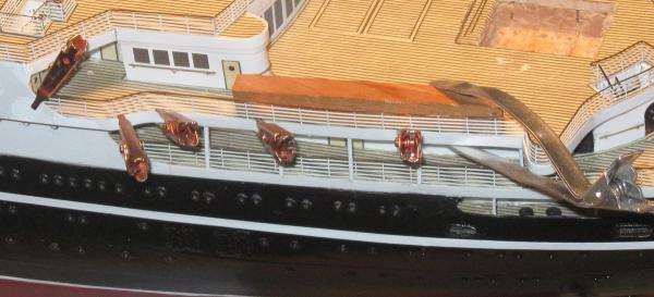
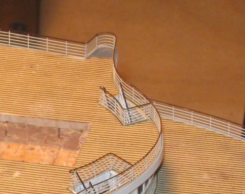
Build log 10 – railings Thank you all, as always, for your likes and comments. Please keep them coming. A belated Happy Columbus Day to my Italian-American friends and to all of my Canadian friends, a very Happy Thanksgiving. I was going to post this on Monday as a longer piece, but when I did, the system crashed and would not let me back on the site for a while. I think it had to do with my trying to download too many photos at once, so I have broken it down into two sections. The next will cover the 3rd class pool and will be posted right away, if I do it right. In the last segment I showed the railings that were installed under the boats on the Boat Deck. I think they really set off the decks and give them a sense of human scale without putting figures on the ship, which my customer does not want. Here is how they are set up. All of the railings are from the Gold Medal Models photoetched brass sheet designated “1/192 Merchant Ship”. The sheet was designed to be used with models of that scale of the Titanic and Lusitania, but the railings and other details are perfect for any ocean liner. The fret is 0.010” thick and made from an alloy that is quite stiff and strong, yet bendable with minimal springback. It is not inexpensive, but well worth the money for several important details that I cannot produce on my own. The sheet has 12 lengths of 5-bar railing, the most common on ocean liners. 5 of them have a thicker top handrail and 7 do not, but the difference is minimal, and I use them pretty much interchangeably. The sheet is 18” wide, so each length is just under 17” long, making a total of over 200 inches (about 17 running feet) of 5-bar railing. This is enough to do most liner models. There are also lengths of 4-bar and 3-bar railings, which were used around some of the crew decks, although not on the Doria. 2-bar and 1-bar railings are provided, but are of limited use. The first thing I do is to give the entire sheet a few coats of white primer. This prepares the railings for whatever I want to do with them. I don’t use the gloss white because the top rail gets hand-painted dark brown with artists’ acrylic paint, which adheres better over the primer. The railings are attached to the perimeter of the sheet and to each other with tiny tabs that are etched halfway through. I cut the rest of the way through on a cutting mat by pressing straight down with a sturdy #10 blade, then sanding off any resulting nub. Working with the railings is pretty easy if I am gentle and use the right tools. Once a length of railing is freed and painted it can be cut to length with sharp scissors with hardened blades. I have a pair of titanium ones that are only used for this task and have lasted many years. Bending railings is done with a pair of flat-jaw pliers and a piece of hardwood. The sides of the pliers have to align and form a flat face. The railing is held in the jaws with the edge of the pliers along one of the vertical posts or parallel to it. The rail is folded against the hardwood, making a tight, straight bend. The angle of the first bend is usually right around 90 degrees, but it is adjusted as needed with gentle pressure before the pliers are opened. Where the railing has to curve it is wrapped around a dowel that is a bit smaller than the desired diameter. Springback opens the railing to the final size. In the photo you can see that when I cut one end I left an extra length of the handrail attached. This will later be bent and trimmed to mate with the handrail of a stairway leading between decks. The GMM fret provides stairways in three sizes to match most deck heights. There are ten with 16 treads, twelve with 12 treads, and eight with 6 treads. For the Doria I needed all three sizes. The fret also provides scale life preservers and even cargo hooks. The stair treads are painted grey (or brown if they were wood) while still on the fret. They are freed by cutting four attachment points and the handrails are painted. Then the sides have to be bent up. The problem is that the sides cannot be bent with the flat jawed pliers, which are too wide to fit between them. I first tried a flat jawed needle nosed pliers, but it was not really satisfactory. The thickness of the brass being held meant that the tips did not close and the piece was loose. This made the bend sloppy and out of true. Then I realized that I had a clamp with straight, parallel, square jaws – my dial calipers. It worked a treat. With these few techniques the railings could be bent to whatever shape was needed. Here the railing of the Belvidere Deck is being installed at a later stage of the model. The perimeter strips of styrene around the deck edge form a raised lip which is filled with white glue on the end of a toothpick. The bottom rail is also painted with white glue to make sure there is complete contact between the mating surfaces. The flat-jawed copper clamps are used to hold the railing until the glue sets. To make sure the railing is vertical as the glue dries, especially when there is a long straight length, a piece of square wood is softly clamped against the railing with a hair clip. Using these techniques the railings were installed around the decks and stairwells. The aft ends of the decks were the most complex, with curved railings even around the stairwells. Note how the handrail of the stairwell curves back to meet, almost, the stairway handrail. Without these photoetched aftermarket parts I could not begin to build such a realistic and detailed model. A heartfelt shoutout goes to Loren Perry of GMM. I am looking forward to using even more modern techniques in future projects. Of course, I could get really obsessive and populate the model with figures, or even scale sized deck chairs. Then I could rearrange them whenever disaster loomed. Dan


- 108 replies
-
- 13
-
-
- andrea doria
- ocean liner
- (and 1 more)
-
Hi Nils - AOL had a glitch with my MSW emails, so I was out of the loop for a while. You have accomplished great work in that time. The plating and rivets look perfect for your artistic vision of the model. I don't know a supplier of aluminum, self-adhesive foil, but I get that type of foil in copper from stained glass craft suppliers. They are great for copper plating a sailing ship since they come in so many widths. Maybe that can work for you if you are painting the hull. Dan
- 2,625 replies
-
- 6
-
-
- kaiser wilhelm der grosse
- passenger steamer
- (and 1 more)
-
Hi Bob - Just linked back to your build. Really good work on the kit. Your stern gallery and lights came out very well, and the contrasting colors of the hull planks will really pop when you get a finish on them. Quite remarkable when considering how fully stocked your shop is not. A suggestion, if you don't mind - a dedicated digital camera, even one in the $200 range, will give you much better results and will let you see your work in much greater detail. I know that I am always going back to the model after looking at my construction photos. Best of success. You're off to an excellent start. Dan
-
Hi Bob - my eyes are not what they used to be, and they never were that good, but I enlarged the photo around the anchor and I just see portholes, not rivets On the other hand, when I squint a bit I see a double line of rivets in a "Z" pattern down the side of the stem just where the hull plates would be secured. They might well be like the rivets on Nils' excellent rudder. Curiouser and curiouser ... Dan


- 2,625 replies
-
- 9
-
-
- kaiser wilhelm der grosse
- passenger steamer
- (and 1 more)