shipmodel
-
Posts
941 -
Joined
-
Last visited
Content Type
Profiles
Forums
Gallery
Events
Everything posted by shipmodel
-
 Hi Marc - I don't know if you can use fimo or the US equivalent, Sculpey, to make the mold. I know that it is great for the carvings themselves, but wonder about it capturing the detail that you want in the negative mold. I don't know if your idea of stamping out the molds will work. If you are using a latex RTV (room temperature vulcanized) mold, it will not hold the shape until it is fully cured. But you can make one small one, then use the master and the first molded one to make two more molds, then use them to make four copies, then eight, then 16, etc, etc. until you can fill the universe with them - LOL For the carvings I have had success with a two-part plastic product called Alumilite that mixes and pours into the mold. It hardens quickly and holds excellent detail. Dan
- 2,699 replies
-
- 4
-

-
- heller
- soleil royal
- (and 9 more)
-
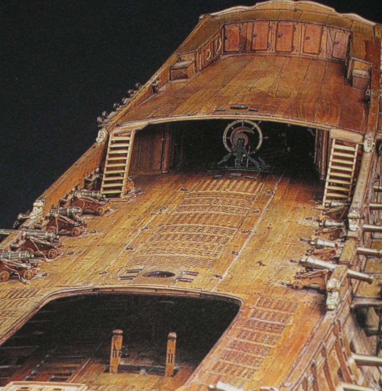
Hi Chuck - I agree with Highlander that the chase guns would be pointed as high toward the bow as possible when they were in use. The point of a chase port is to fire as directly ahead as possible. You would also want to tack/wear/yaw as little as possible from side to side to get both guns into action. Even then, the rate of fire would be much lower than a broadside gun. There would be plenty of time to slew the gun around as needed to worm, sponge, and reload. If the guns, especially the port one, can be maneuvered with the trucks in back fitted between the knees for the windlass and the bowsprit it looks like there would be just enough room to reload. If you can move the cannon around to that position in the limited space without lifting it off the deck it should have been possible for the crew to do so as well. Just trying to put myself into the shoes of the sailors. Dan
- 1,051 replies
-
- 10
-
-
- cheerful
- Syren Ship Model Company
- (and 1 more)
-
Nils - The America is at 1:192, like the Andrea Doria, the Rex, and the Uruguay. Why change a winning style. The chairs are the same scale. I don't remember where I got them, but I still have one and it measures out to 3/8", which is right if the chair is 6 feet long. Was it Tom's Modelworks ? If anyone knows let me know, because I might need some more for a future project. Dan
- 2,625 replies
-
- 6
-
-
- kaiser wilhelm der grosse
- passenger steamer
- (and 1 more)
-
Hi Nils - No, there is no build log for the SS America. I did it before I joined MSW. I have lots of construction photos, so I may post them one day. I thought that I had some in the NRG home page Gallery, but I can't seem to find them any more. The railings are photoetch from Gold Medal Models. I spray the entire sheet with white primer and paint. Then the railing lengths are individually cut off and the handrail is brush painted with acrylics. I may have mentioned this in the build log for the Andrea Doria. Be well Dan
- 2,625 replies
-
- 6
-
-
- kaiser wilhelm der grosse
- passenger steamer
- (and 1 more)
-
Hi Nils - Checking in after the summer and love what I am seeing. I second the compliments from everyone else and look forward to following your progress. As for the deck chairs, here is a photo of the same photoetched ones that I used on the SS America. I did decide to paint them with a simple brown spray, holding them down by sticking them to masking tape laid face up on some wood scrap. They came off easily after painting without destroying the CA joints. Be well Dan

- 2,625 replies
-
- 19
-
-
- kaiser wilhelm der grosse
- passenger steamer
- (and 1 more)
-
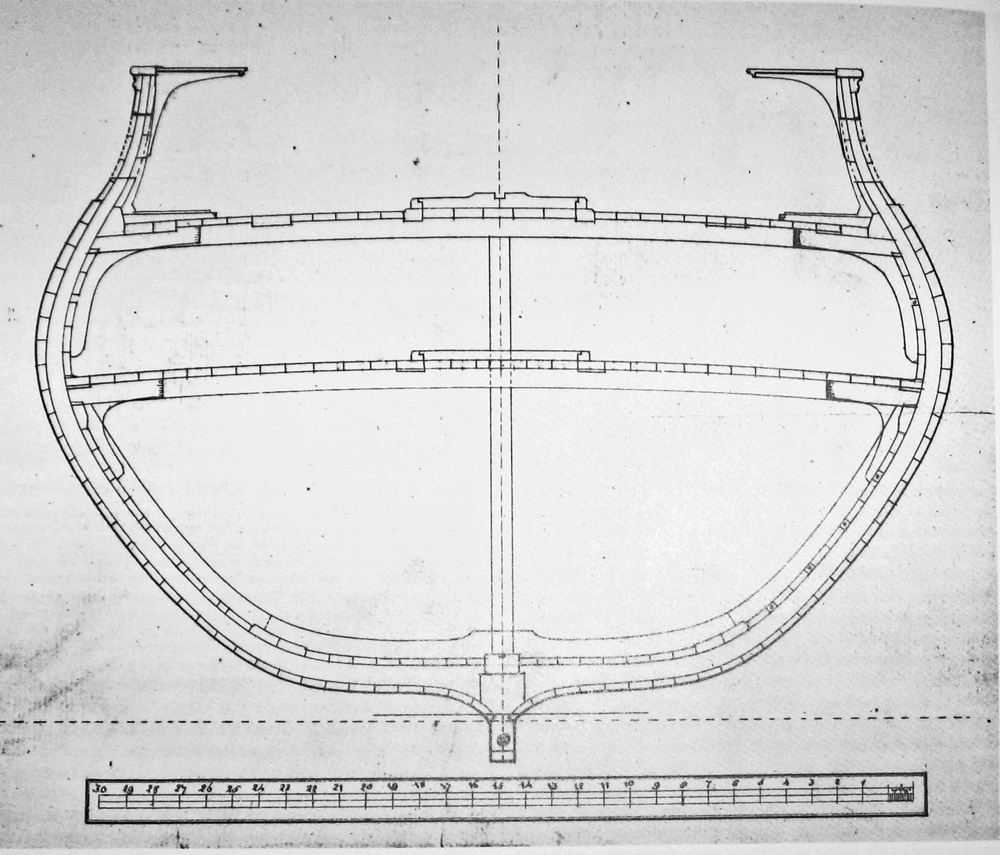
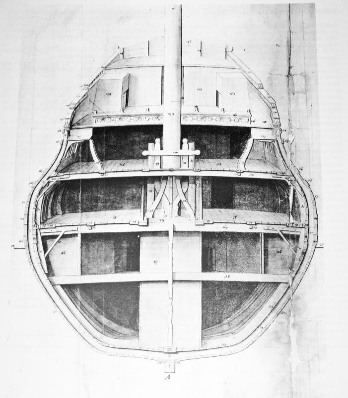
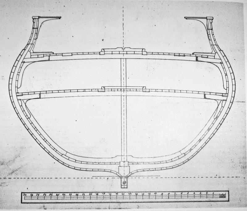
Hi Mark - Checking in again and love what I am seeing. Those deck beams are very nicely done, and you should be justifiably proud of them. As for decking, you have to be careful about the differences between British and French practice. Since the French were strategically blockaded by the British for most of this period, their ship designs favored speed over carrying capacity. With lighter hulls and scantlings they could make more knots, but the ships 'worked' much more than their British counterpart of similar size. To counteract this they strengthened the decks with longitudinal stiffeners called binding strakes that were thicker and set into the deck beams, much the way the stringers stiffened the fuselage in those balsa wood planes we all built as kids. Here are several contemporary cross sections of French ships. Note that the outer binding strakes are set into the deck beams but do not rise above the deck surface. However, the ones toward the center rise above the rest of the deck level. In fact, the entire center section of the deck is raised. Frequently these binding strakes are shown on models as being contrasting color from the rest of the deck. Whether this was true on actual ships, I do not know. Further, as seen in the models, the gratings are set flush with this raised section of deck and do not have the coamings that are such a feature of British ships. Didn't mean to make extra work for you, but hope it helps. Be well Dan


-
Hi Mark - I guess we came up with similar solutions. Not surprising, but nice to know. Is it the angle of the photos, or do your structural arches angle down across the line of the wales? The drawing seems to show them more level with the wales. Dan
-
Just beautiful, Druxey - Those serpents on the oar blades are above and beyond magnificent at your scale. You are an artist in the art of ship modeling. Thanks for sharing your talents. Dan
- 641 replies
-
- 3
-
-
- greenwich hospital
- barge
- (and 1 more)
-
Hi Mark - Very nice progress since I last looked in. It will be a fine model when finished. I puzzled over the stern galleries on all my sailing models and found that I can visualize them best when I just make them up first as a solid. I take a block of an easily worked wood like balsa or basswood and cut and carve the surface that mates with the ship, then the sides and last, the outer face. I am always surprised at how different the final shape is from what I imagined from the plans. With this in hand I can make more intelligent decisions on how to fit it out. I have even cut apart the solid to make up structural members, knowing that they already fit together. Best of success. Dan
-
Hi Ken - Just catching up on your build and enjoying the nice workmanship. Thanks for sharing. I think you have made the better choice on the gangway. Utility would have trumped looks all the time, back then. Your solution looks more user friendly, where the outer handholds and steps match with the stairway on the other side of the gangway, and the spacing of the steps leads to the caprail and then one more up to the gangway, which is as high as possible to clear headroom for the gunners. The stairs could then be easily taken down and stowed when clearing for action. Lookin' good. Dan
- 481 replies
-
- 1
-
-
- rattlesnake
- model shipways
- (and 1 more)
-
Top notch work, Nils. It's those eye-catching complicated fittings that make your work so captivating. Dan
- 2,625 replies
-
- 5
-
-
- kaiser wilhelm der grosse
- passenger steamer
- (and 1 more)
-
Hi Druxey - Gerhard said it perfectly. Sweet work. . . I didn't realize until I saw your build that the access to the cabin was only from aft, and there is no door towards the bow. That means that the passenger boarding was from over their private deck at the stern which was probably off limits to the crew except for the ship captain (helmsman?) standing on his separate raised platform. That also explains the extensions of the upper strakes, which I imagined were only decorative. I learn so much from your build without your even saying anything. Thanks Dan
- 641 replies
-
- 8
-
-
- greenwich hospital
- barge
- (and 1 more)
-
Druxey - That explains it. They will look really good with glass. In the scale that you are working, will a microscope slide cover be large enough? As for PFB, I did not remember the windows from when I saw Lloyd McCaffery's version, but then I was focused on the figure that Lloyd carved of himself seated on a thwart and turning a splice into a line. That man sure can carve wood. Be well Dan
- 641 replies
-
- 5
-
-
- greenwich hospital
- barge
- (and 1 more)
-
Hi Druxey - The last several posts have been nothing less than stunning - and you know that I don't give out compliments like that lightly. As usual you remind me why I love the artistic puzzle that is model shipcraft, and how how high you and a few others set the bar. Many thanks for the inspiration. If I can put in one thought, it is that the openings might not have been glazed at all, but had roll down screens of thin oiled fabric, much like the stagecoaches of the same period. They would have been used only in inclement weather. Light curtains for privacy also could be hung. My sources here are closer to Forrester and O'Brian than to actual historic research, so I could be wildly off base. Be well Dan
- 641 replies
-
- 7
-
-
- greenwich hospital
- barge
- (and 1 more)
-
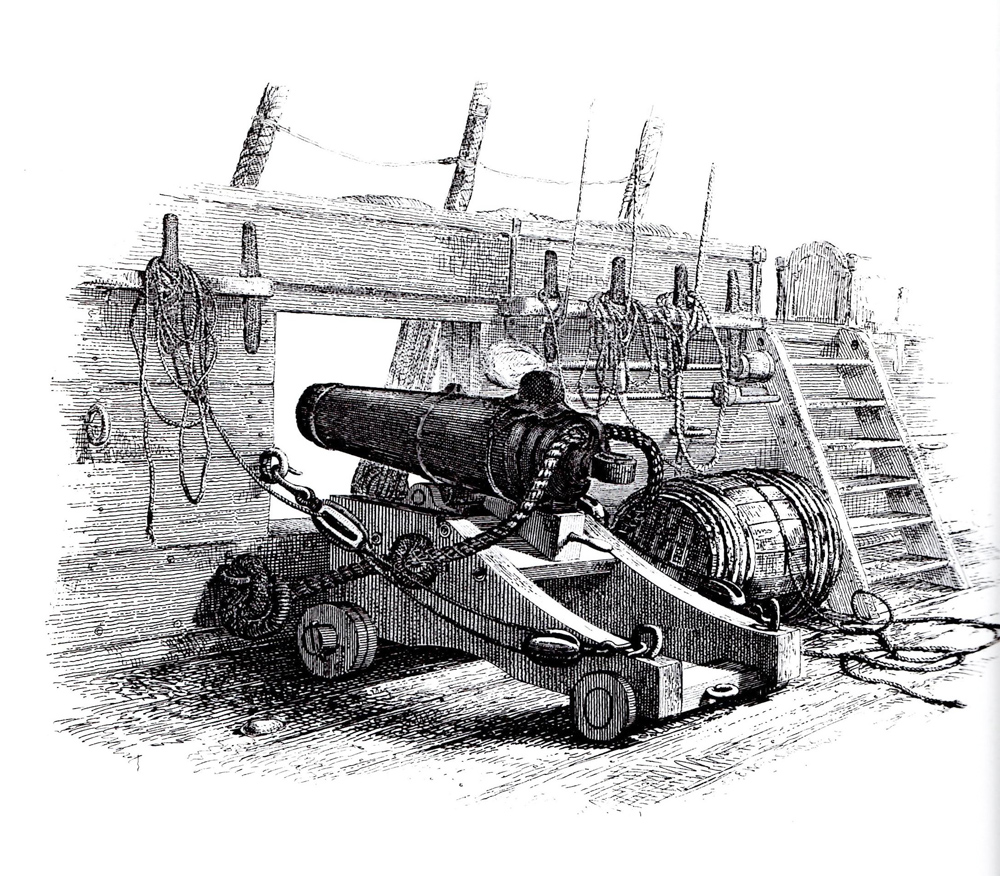
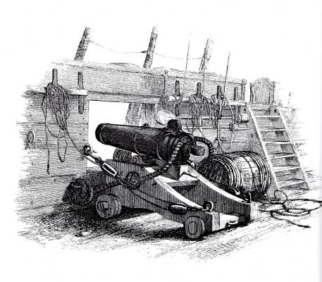
Hi Chuck - Breeching rope looks good, and the rest of the carronade is up to your usual excellent standards. I don't know if you have seen this, but E.W. Cooke did a drawing of a 12-pounder carronade on an English brig of war in the mid 1800s. Although I usually trust an artist to reproduce what he sees, the breaching rope here sure looks like there wouldn't be much recoil allowed, unless the excess line is coiled at the bulwark. Following along with interest. Dan
- 1,051 replies
-
- 10
-
-
- cheerful
- Syren Ship Model Company
- (and 1 more)
-
Congratulations, Grant. She is a beautiful build. The photos of the ends really demonstrate your fidelity to engineering and construction methods. The deck shots show your fine artistic use of wood colors and contrasts. Bravo. Dan
- 456 replies
-
- 3
-
-
- finished
- bomb ketch
- (and 2 more)
-
Hi Druxey - Always a pleasure to watch you work. I have long wanted to do a similar ceremonial barge, but my questionable skills at the final decorative fiddly bits always held me back. I have a handy supply of popcorn and Makers Mark and have settled in to enjoy. I am wondering how you will make the butt joints between planks in each strake. In full size practice they are beveled scarfs pinned with the same rivets as the lap between the planks. Are your joints going to lie on the ribs that you will install later? Dan
- 641 replies
-
- 7
-
-
- greenwich hospital
- barge
- (and 1 more)
-
Hi Grant - I join with everyone else in admiring your deadeyes. Very nice work. Sorry about the chainplates. At least they gave out now rather than when you tried to rig the shrouds. There is a lot of stress here, and soldering, even silver soldering has never held up for me. Here is how I worked out the issue on the Queen Anne's Revenge, whose chainplates look a lot like yours: The upper hook is narrowed to fit the loop of the deadeye strop. Once the deadeye is installed the loop is closed and soldered. It is also strengthened by being sandwiched between the channel and the cap molding so it cannot open. I did not have any failures during rigging. I really enjoy your log and how you are solving the problems that come up. Thanks for sharing. Dan
- 456 replies
-
- 8
-
-
- finished
- bomb ketch
- (and 2 more)
-
Hi Ken - Looking really good. Nice work on the wolf-hounds. From experience I suggest that you locate and dry-fit the catheads before working out the top rail. They fit together and the location of the cathead has a major influence on the size and shape of that top rail. Dan
- 481 replies
-
- 1
-
-
- rattlesnake
- model shipways
- (and 1 more)
-
Tom - Looks like it could go either way. Looking forward to seeing how it comes out. Be well Dan
- 1,354 replies
-
- 1
-
-
- constitution
- model shipways
- (and 1 more)
-
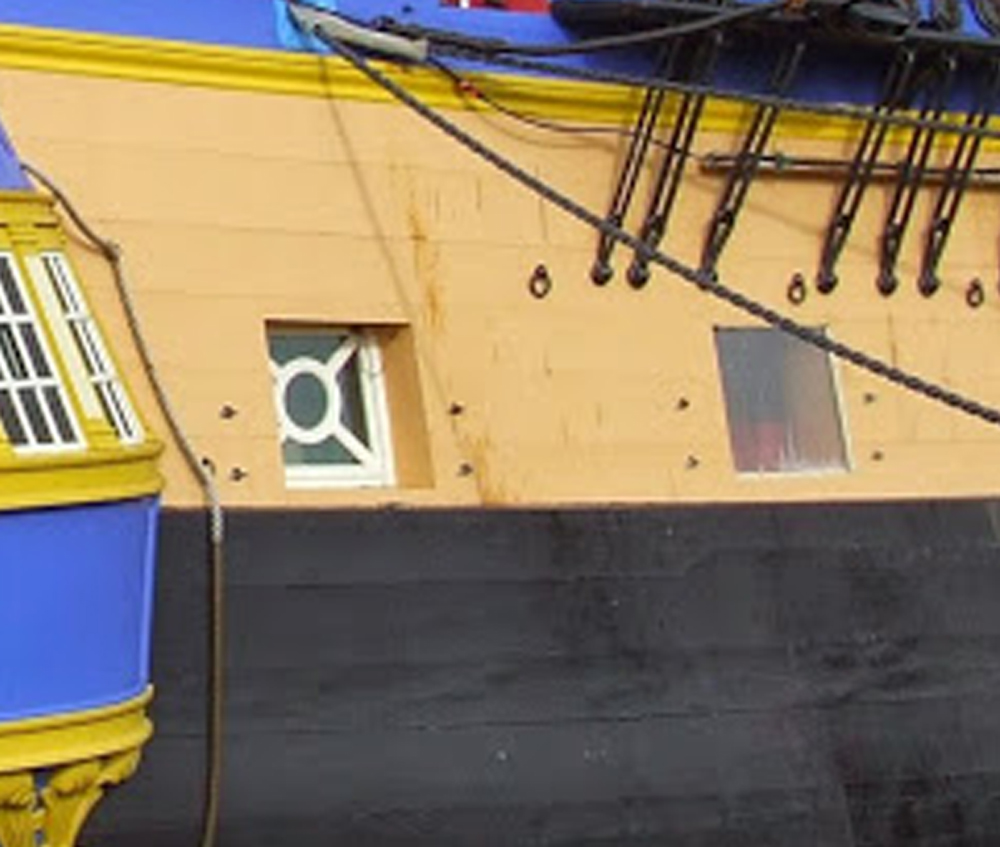
Tom - Thanks for showing the artwork. To my mind this does not look like a cannon muzzle, but perhaps a wooden framework that the canvas was mounted to. The circle with outward rays was a common pattern for glass windows at the time. It is very different from the artist's drawing of the cannon in the port on the right. A wooden framework could also solve the problem of how to secure the canvas in the port since it did not have to roll down. The photo is of the reconstructed L'Hermione. Dan

- 1,354 replies
-
- 3
-
-
- constitution
- model shipways
- (and 1 more)
-
Hi Nils and Happy New Year to you too. I will be following along this coming year and looking forward to many excellent developments. Be well Dan
- 2,625 replies
-
- 5
-
-
- kaiser wilhelm der grosse
- passenger steamer
- (and 1 more)
-
Hi Tom - Just looked over this log and was quite impressed. You are getting excellent results technically and artistically, and with full attention to historic accuracy. Bravo. I am no Constitution expert, and I have not looked at any of the artwork that was mentioned, but I am wondering about those canvas gunport covers. The reason for canvas rather than wood, I would think, was so the captain could roll them down a bit to get some air without having to open them fully, or at least halfway by removing the upper split cover. In that case, would there have been a hole, or would the cannon be stowed inboard somewhere with a solid canvas curtain to cover the port? Just my brain spinning along. If I am way off base, just ignore this. Be well Dan
- 1,354 replies
-
- 1
-
-
- constitution
- model shipways
- (and 1 more)
-
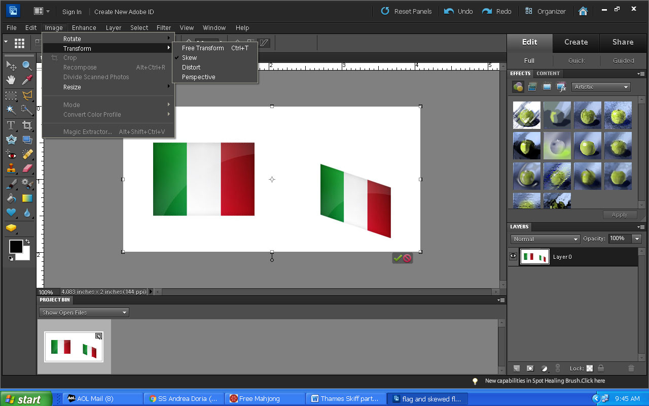
Hi all. Yes, i think my customer will be pleased. With some small exceptions I am happy with it too, which is not the same thing at all. Tom - I go over my flag method in the Queen Anne's Revenge log. It is spelled out in some length on page 11, but here is a shorter version: I find a digital image of the flag on the net and import it into my PhotoShop program. I use an older, middle priced version called Elements 10, but there are lots of similar programs which can do similar things. In PhotoShop I resize the image and then skew down the outer end of the flag so it becomes a parallelogram. Doing this allows the flag to hang more naturally, without a buildup of material at the lower inside corner. Here is a screen capture of the PhotoShop program with the Image/Transform/Skew menus opened and the original and skewed images of the flag shown. Then it is just a question of selecting the material that fits my scale; silkspan here and batik for the QAR. I do print it out onto a test piece of paper first, using just a home inkjet printer. I tape a smaller piece of silkspan over the image, then print again over the top. It gets sealed, then cut out with a little extra to secure it to the halyard, hung and curled till I like the look. Hope that explains it. Thanks again for the compliments and for following along. Be well. Dan

- 108 replies
-
- 5
-
-
- andrea doria
- ocean liner
- (and 1 more)
-
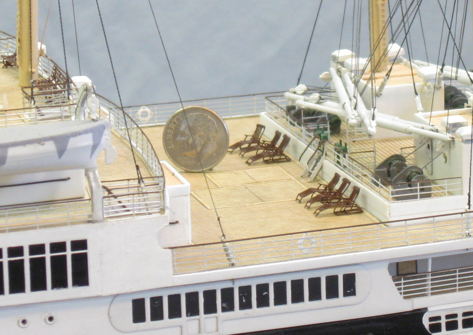
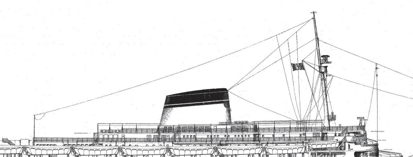
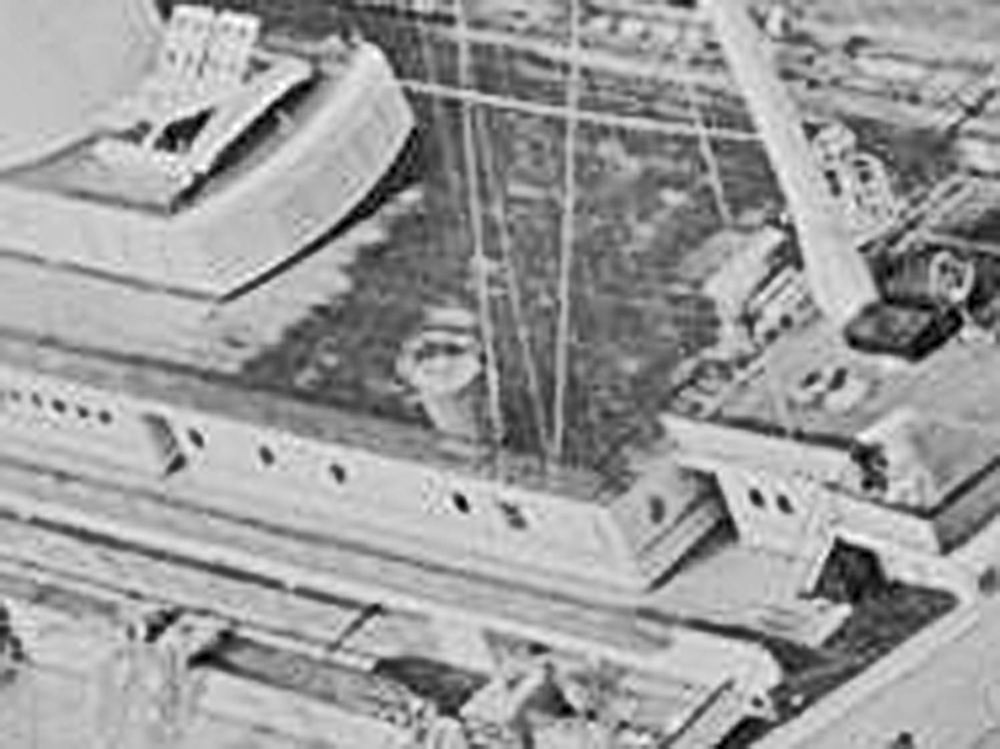
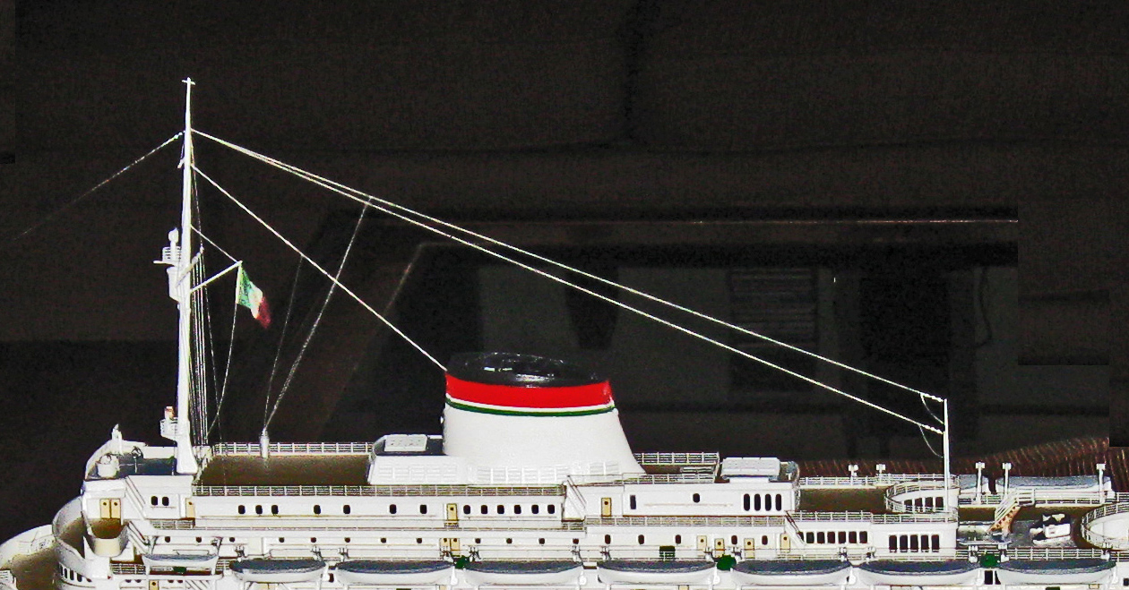
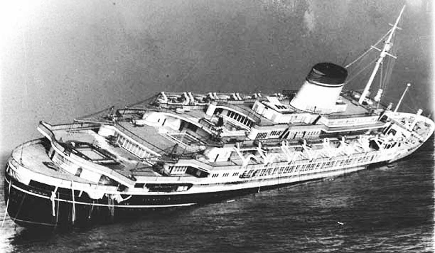
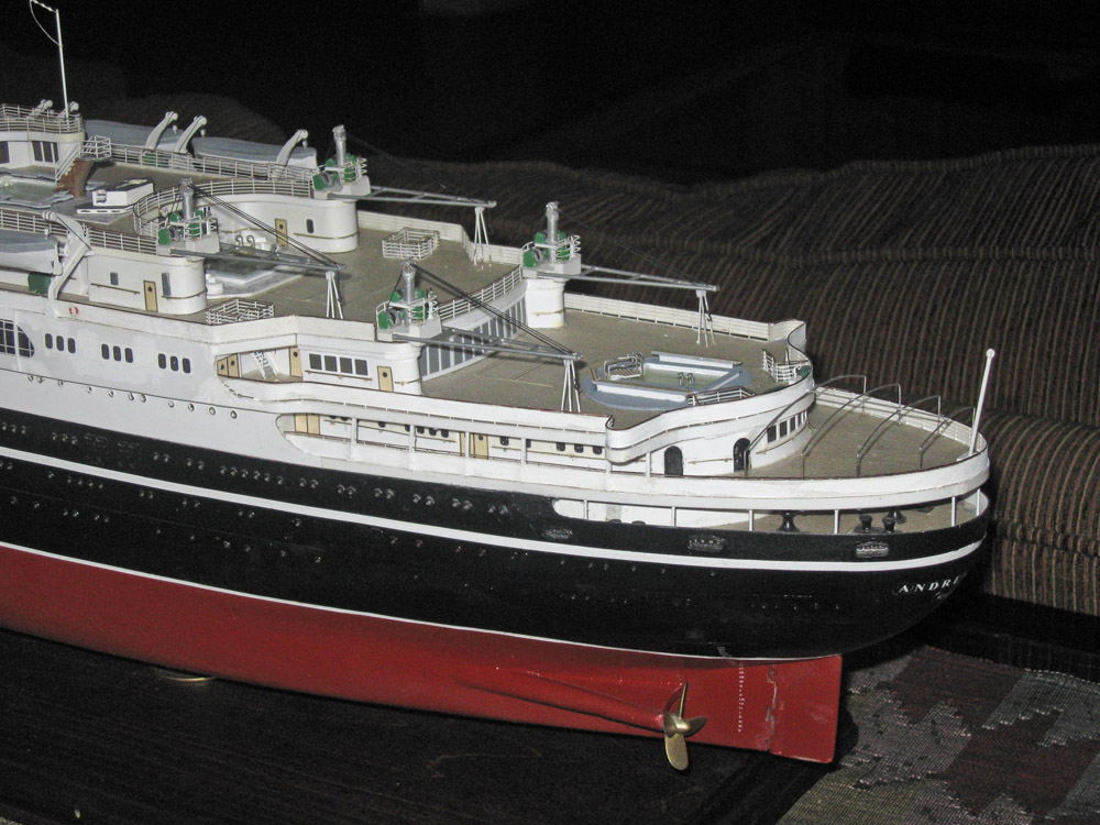
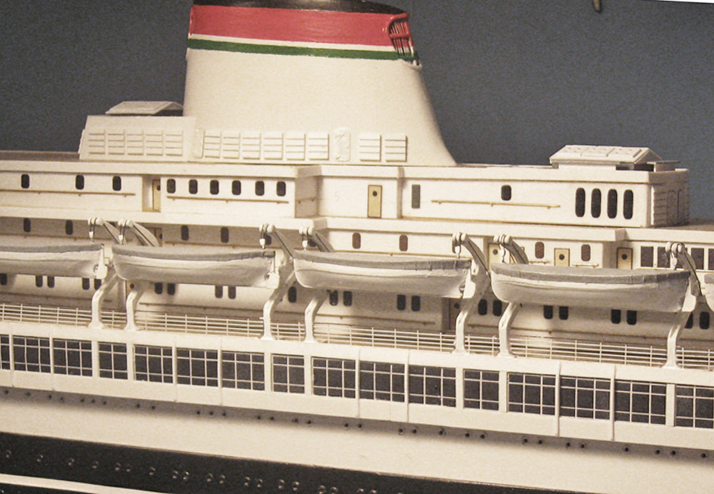
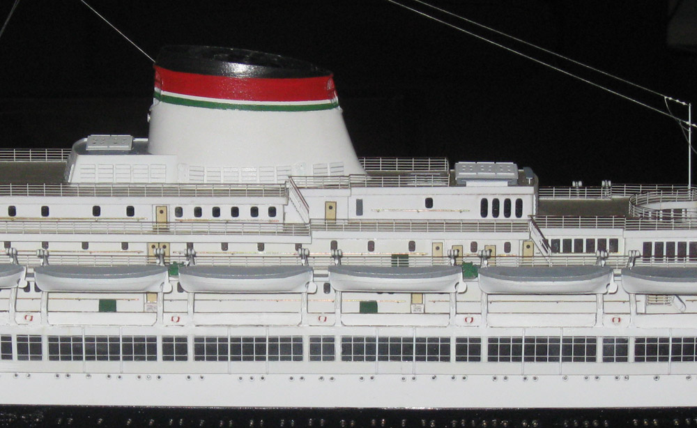
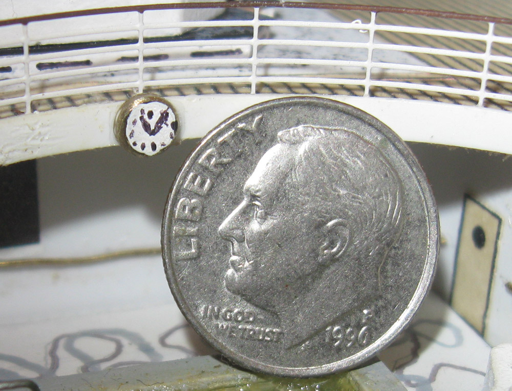
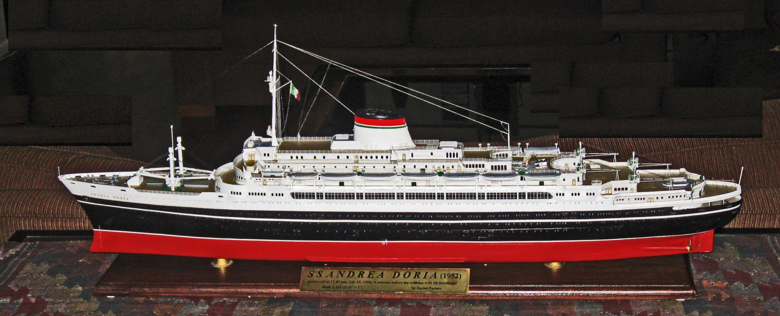
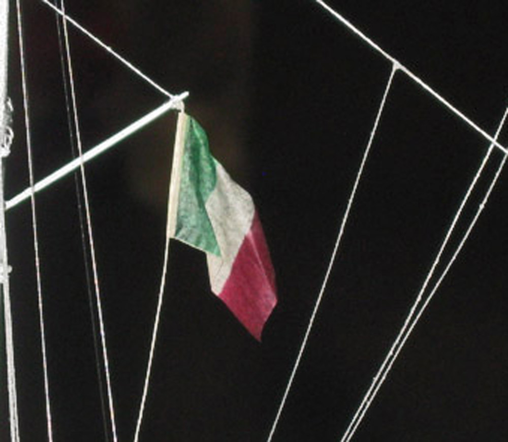
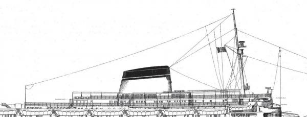
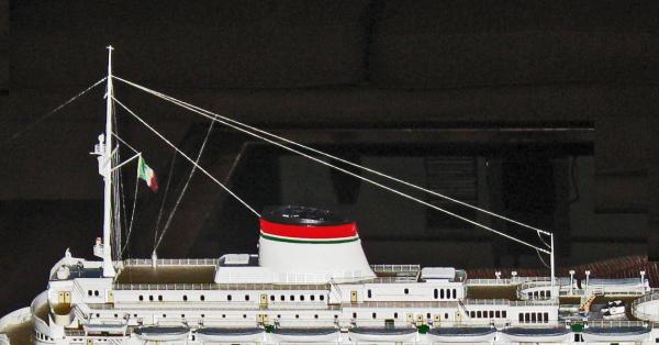
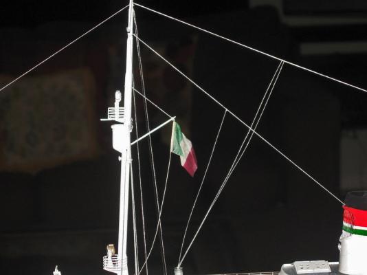
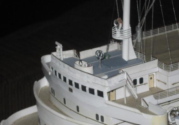
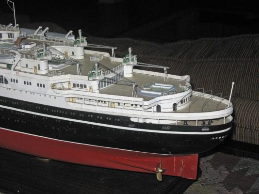
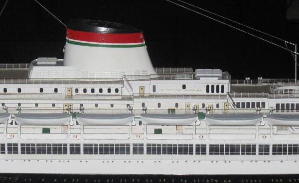
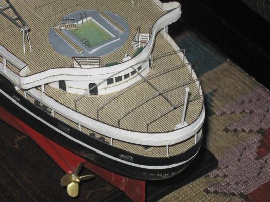
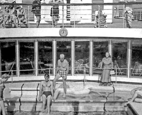
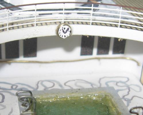
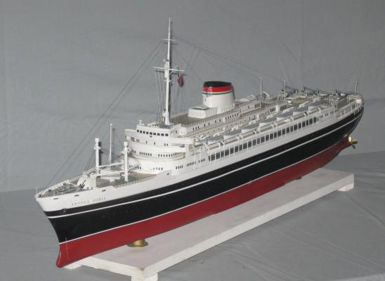
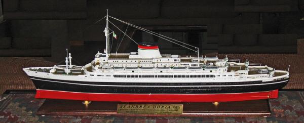
Build Log 15 – Final Details Hi and Happy New Year to all, and thanks as ever for the likes and comments. This will be the last installment of this build log, covering the final details that add another level of interest to the model. Many of these are elements that can be changed at the discretion of the captain, so I used as my guide the photographs taken at the time of the sinking. The first detail was the wires for the short wave radio antenna. These do not show up very well in photographs since they are so thin. On the plans they are shown, but not separated from the mast support wires. Close examination of various photographs show that not all of these wires were installed on the actual ship. Presumably the antenna wires changed as the radio was upgraded during the life of the ship. There is a cylindrical structure on the starboard side of the Sun Deck just aft of the Command Deck area. Several wires lead to it so, although it is never identified, it is clearly part of the radio system. Without any clear guide, I decided to include three wires for the antenna. Two lead from near the top of the mast to thin poles at the aft ends, port and starboard, on the Lido Deck. The antenna wires are separated from the poles by short lines with three insulators. These were made by mixing white paint with white glue, then attaching small drops to the line with a toothpick. Several coats were needed since the glue shrinks as it dries and had to be filled out again. The third line runs from a bit lower on the mast to the top of the funnel. All three lines are then connected to the radio fitting with vertical lines. All of the radio wires were made from fine embroidery linen in an off-white tone. I tried several other materials and colors, but this gave the best look, in my opinion. It is light enough to show up in most light, but thin enough not to be overpowering. In photographs of the ship taken on different days, there appear or disappear various sets of canvas railing cloths to protect the passengers from sea spray. These were hung on the outside of the railings and laced to them. On the day of the sinking there were railing cloths up to the level of the boat deck and around the command deck. I modeled the cloths with stiffened batik fabric cut to fit and glued against the appropriate railings. Unfortunately, once everything was dry the fabric proved too transparent, and had to be given a coat of opaque white acrylic. But the glue proved too strong and I risked damage to the rails, so the first ones had to be hand painted on the model, while I could paint later ones before installation. Live and learn, eh? I was surprised at how much of a visual difference the cloths made to the overall appearance of the model, especially when viewed from amidships. Here are before and after photos. The passengers were also protected from the weather and sun by canvas awnings supported by metal frames, although no photo shows the awnings spread. Perhaps that was only done in port. The simple frames on the Lido deck are mostly hidden behind the lifeboats, so I did not model them, but the aft taffrail deck was set up with a large awning over a complicated and interesting metal frame. It would be a nice element to include. The frame was made up of four flat arches of differing widths set across the deck and tilting down from forward to aft. They were connected to each other with a straight bar running along the centerline. For the model the frames were bent up from 0.030” brass rod. Getting them to fit predrilled holes in the deck and still have the correct arch took a lot of trials and even more errors. Once they were shaped the problems first started. I planned to solder them together in a jig, then electroplate them in chrome. I was spectacularly unsuccessful. Once soldered in the jig, the assembly bent and/or came apart as it was removed. Several times. Metalworking skills are not my strong suit. I never even attempted electroplating. The final solution was to mount the arches on the model with the connecting bar attached with small dots of epoxy. Once everything was set in place the deck was protected with a piece of paper toweling and the brass was hand painted with primer then silver acrylic paint. Happily, it turned out to be quite strong and convincingly metallic. Some small details were added around the ship. A dozen green storage bins were scattered around, a searchlight was installed on the aft end of the Promenade Deck near the third class pool, and photoetched life preserver rings were mounted outside of the railing cloths on the boat deck. Ensign staffs were mounted at the extreme bow and stern. All of these give the model a bit more 'texture' and realism. It was finally time, a year after laying the keel, to hang the flag on the ship and get her ready for launch. It was made in my usual way by printing out a skewed image of the flag. At this scale the material was silkspan, which is transparent enough that I did not have to print the reverse side. It was hung on a halyard running from the tip of a gaff to a cleat on the base of the mast, then misted with water and gently curled. There was one final detail to attend to. You may have noticed in earlier photographs of the first and second class pools that a clock was mounted on the overhang at the forward end of each area. I made them up from 1/10” o.d. brass tubing filled with a wooden dowel. After flush sanding the wood the brass bezel was chamfered on a sanding belt. The wooden face was painted white. Tiny black dots for the numbers were touched on with the tip of a sharpened toothpick. With my finest 10/0 brush the hands were put on. The extreme close-up photos show that I was less than perfect, but with the entire clock being less than 1/8" in diameter, I have reached the limits of my talents. The clocks are set to 11:05 p.m. In five minutes the lives of Linda Morgan’s parents, sister, and dozens of others will end and she will be thrust into unwanted publicity. In just five minutes. But for now, in miniature, she sails off the workbench to the customer. I hope you liked the journey despite my sometimes clunky sense of humor. I will post a photo tour of the finished model when I can. Until then . . . Be well Dan


- 108 replies
-
- 21
-
-
- andrea doria
- ocean liner
- (and 1 more)