shipmodel
-
Posts
941 -
Joined
-
Last visited
Content Type
Profiles
Forums
Gallery
Events
Everything posted by shipmodel
-
 Bob - That looks well nigh perfect. The only thing that would have to change is that the staves meet dead center at the lower forward edge, not on either side. Is that a big deal? Dan
- 287 replies
-
- 4
-

-
- michelangelo
- ocean liner
- (and 1 more)
-
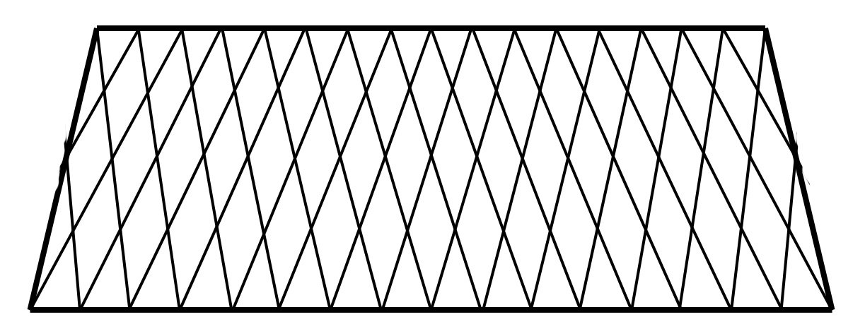
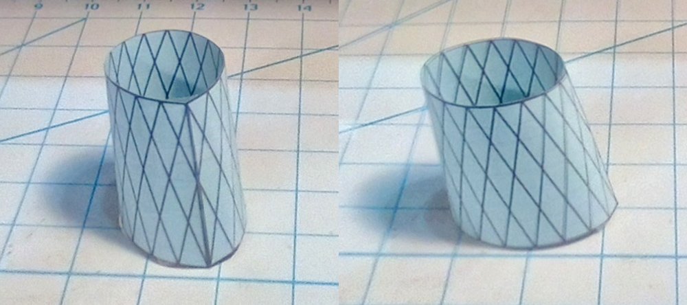
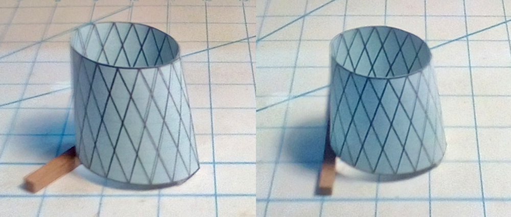
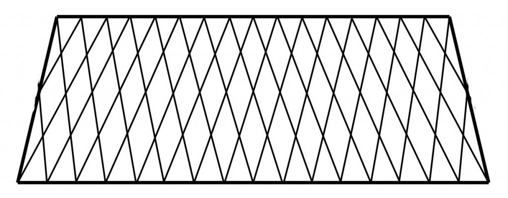
Hi Michael, Bob - Thanks for your input. Yes, it should be possible to lay out the framework mathematically, but it is beyond my capabilities. It is not as simple as doing a flat expansion. I can determine the circumferences of the base and top ovals. The base is 37mm on the long axis and 22mm on the short one. Using the : Pi x (square root of 2) x ((1/2 long axis)squared + (1/2 short axis)squared) - this results in a circumference of 96mm, or 6mm between each of the 16 joinder points around the base. Similarly, the top oval is 31 x 19, giving a circumference of 80mm, or 5mm between points. I can lay out the grid as a trapezoid with those lengths and a height of 34mm as taken from the plans. But when I pull the sides around to form a tapered cylinder, much less a tapered ovoid, the top and bottom edges deform and do not remain flat and horizontal. As you can see, there is a point developed at the lower bow, matched by a dip at the top. It also makes the funnel lean back aft. If I straighten up the aft edge, as on the ship, the problem is more pronounced. To correct these issues, the top and bottom of the layout have to be curved. If this were a tapered cylinder, the curve would be smooth and continuous. But this is an oval, and the curve will be tighter at the ends than in the middle. Deriving these lines, top and bottom, is what is out of my reach. So, at the moment I am still working on some sort of lattice built up over a form. I will test Michael’s idea of using flat strips that are rounded by loading them with paint. I am sure that numerous failures will be required before two acceptable ones are produced. Bob, I would love to work with you on doing it with 3-D printing. I have no experience with it, but it looks cool. Let’s talk when I get closer to needing them. Be well Dan
- 287 replies
-
- 7
-
-
- michelangelo
- ocean liner
- (and 1 more)
-
Aaaaarrrggghhhhhh ! I have enough trouble with the one that whispers, "What harm can one doughnut do?" :-)) Dan
- 287 replies
-
- 9
-
-
- michelangelo
- ocean liner
- (and 1 more)
-
Michael - I know that your metalworking skills are far above mine. But if you can half lap 80 interlocking intersections in brass rod of .03" diameter you get my vote for the modelers' Hall of Fame. :-)) Dan
- 287 replies
-
- 8
-
-
- michelangelo
- ocean liner
- (and 1 more)
-
Pulling up a chair to watch. The Hahn method is one that I have always admired, but never tried. Always something new to learn. Boy, and I thought I had a lot of clamps . . . Be well Dan
-
Hi Michael - glad to have you along. I am thinking along the same channels at the moment, but then what can be done at all of the overlaps, where the staves cross? If I use brass rod the double thickness will make for a very visible lumpy surface, rather than the smooth surface that photoetching would give me. And now I am leaning towards Druxey . . . This sort of thing keeps me up at night - in a good way. For me, it is one of the best parts of ship modeling. Be well Dan
- 287 replies
-
- 8
-
-
- michelangelo
- ocean liner
- (and 1 more)
-
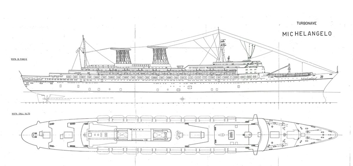
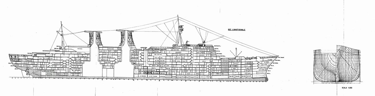
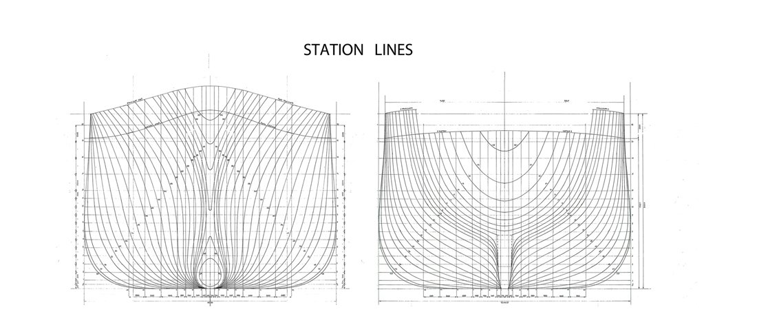
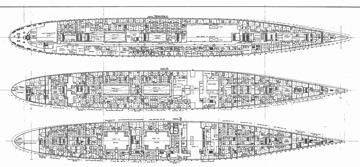
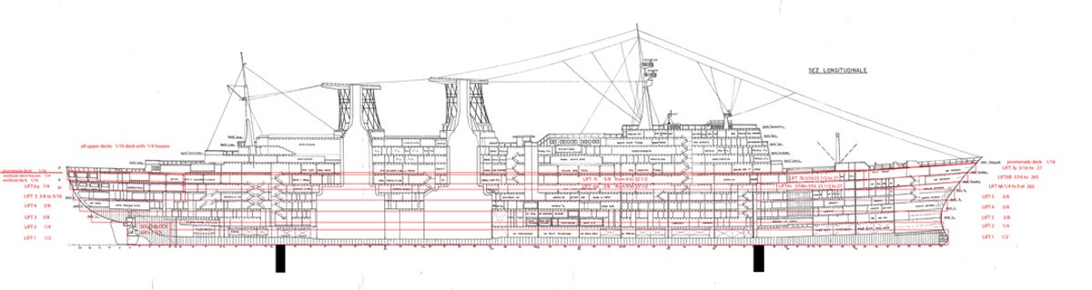
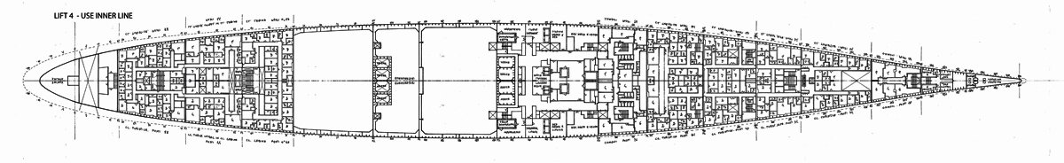
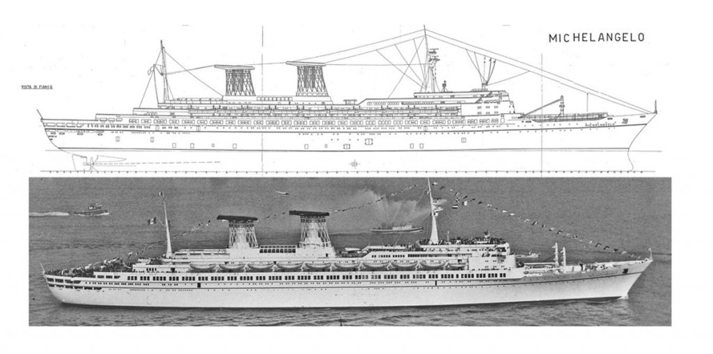
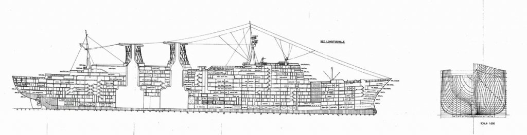
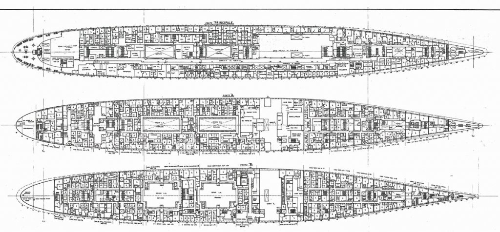
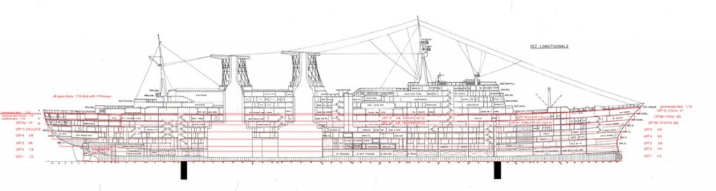
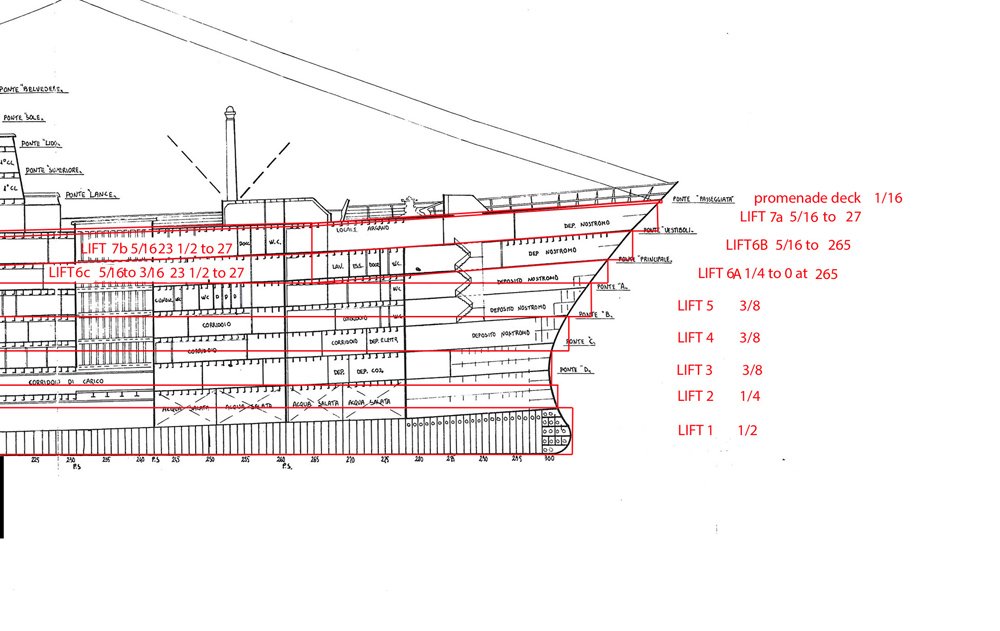
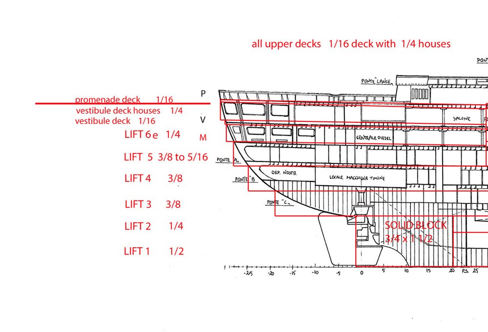
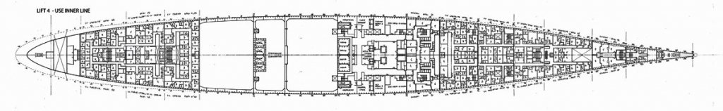
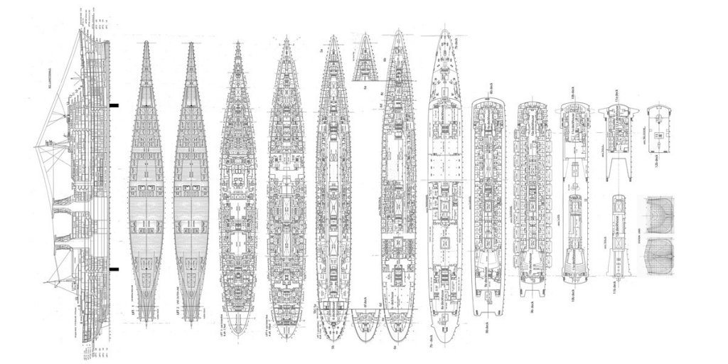
Hi all – The plans were obtained through the good graces of fellow modeler and good guy, Bill Zebb in Connecticut. He is an ocean liner enthusiast, and we got to talking at the NRG Conference in Mystic. He said that he had exactly the plans that I was considering ordering from Italy. They were in his basement somewhere but he would dig them out for me. He did, and they were. Published by the Associazione Navimodellisti Bolognesi at the stated scale of 1:200 they came in two very long paper rolls. Fortunately, this did not phase my blueprint company, who digitized them at 300 px/in. Unfortunately, this made for one huge file which was too large for my Photoshop Elements program to work with. I had to get a friend with a more powerful program to cut the file in segments that I could deal with. The first segment was the overall profile and plan. I wanted them to be printable at the exact size of the model. This was not as simple as reducing by 200/350 since the plans must have been copied a bit off size along the way from the draftsman to my hands. From the usual sources I found that the LOA of the ship was 276.2 m (906 ft 2 in). Reduced to 1/350 this is 78.9 cm or 31.06”. Using the rulers in the program I resized the image until it matched those dimensions. This segment, like all the others, also had some distortion. For example, you can see the vertical lines where the plans were folded at some point. The plan visibly nods down to the right of the right crease, making a bend in the waterline stripe. There are other, smaller defects, all of which were corrected on the final working plans. But these views were used only as guides, so they only needed to be resized. This let me take the photograph of the ship in profile and set them alongside each other as a very handy comparison tool. The first segment to be properly adjusted was the interior cross section and station lines. The cross section is labeled for the various decks, which were all straightened out, piece by piece, using the rotate, skew and transform functions of the program. The plan is also numbered at the keel starting from 0 at the hinge of the rudder. Why this location was used is a mystery to me. These station lines run from 300 at the bow to -25 at the stern. The station lines plan was taken off and straightened separately. When I was happy with the result I cut it apart at the centerline, copied and mirrored each section, then merged it to its partner. Having these views makes it much easier for me to visualize the forward and aft shapes, although the letters and numbers on one side are reversed. Each deck plan was treated similarly. First it was straightened along the centerline. The starboard side, with the station numbers, was separated, mirrored and joined to its partner. This ensured that the decks were symmetrical. Using the station line numbers the size of each was checked and corrected as needed. Here are the plans for decks A, B, and Main. With all the deck plans set, the corrected cross section was divided into horizontal lifts which matched, as much as possible, the deck heights. They were also selected to match basswood plank thicknesses available from National Balsa Co. Each was numbered for reference with thicknesses noted. The rising sheer meant that the line of the lifts does not match the line of the decks, especially at the bow. The first 5 lifts could be flat, but to get the curve of the sheer, lifts 6 and 7 had to be broken up into segments. In fact, lift 6 had to be broken into 5 segments, with 6A being a wedge that tapers from ¼” at the bow to nothing at station line 265. At the stern the problem is similar, but smaller. I could have added a 1/16” wedge on top of lift 5, but it became easier to start with a thicker piece and taper it. I could not make the wedge at the level of lift 6 because this deck has open windows and hawse holes where the interior will be visible. The rising sheer also meant that even flat lifts did not match the deck plans. If the plans had been used without modifications the shapes would have been wrong – sometimes too narrow, sometimes too wide. Each lift was studied to see which deck plan was the best fit for the top of the lift. From lifts 3 and up I had to use the plan from one deck for the stern and another for the bow. Here is lift #4, with the stern of deck C and the bow of deck D. After all of the lifts were laid out, the superstructure decks were sized, adjusted, and lined up matching their locations above the hull plans. It was easiest to work with them in this configuration, but when they were all set it became easier to turn them sideways and print them out on a 36” paper roll. The blueprint company made several copies for very little money, and even redid it free when the first printing proved to be slightly small. Next time, the wood starts flying. Be well Dan


- 287 replies
-
- 12
-
-
- michelangelo
- ocean liner
- (and 1 more)
-
Thanks Ken - I'll check them out. As far as I know, only Michelangelo and her sister, SS Rafaello, had these cages around the funnels. Dan
- 287 replies
-
- 4
-
-
- michelangelo
- ocean liner
- (and 1 more)
-
Well done, Tom - Sorry we won't see her, or you, in New London. On the other hand, you could bring the whole family to see the models. Only $5 to view about 100 quality entries by builders from Boston to Philadelphia. Happy birthday to all Dan
-
Hi all - Nice to see so many familiar faces in the audience. Thanks for the interest. This performance will be at a more relaxed tempo than the 4-page Doria sprint. Michelangelo is at the weekend house which I do not visit much in the winter, so progress is episodic and irregular. Also, my club, the New York Shipcraft Guild, is hosting the Northeast Joint Clubs Ship Model Conference and Show at the end of April. Lots to do and organize. Druxey, I only wish that I could figure out how to make them with photoetch techniques. The first problem is that the cages are not cylinders. They are ovoid, and the top oval is smaller than the base. These are then divided into 16 segments for the points where the vertical staves meet and are secured. Flattening this web has to require curves top and bottom which are joined by a very precise pattern of staves. I don't know that I have the skill or mathematics to make the pattern to be etched. The second problem is that once it is made, I am pretty certain that I could not roll it into the smooth oval cylinder shape needed without messing it up. My current thinking is along the lines of building an internal framework and hand applying the staves made from styrene strips. But I am completely open to suggestions. Fortunately, it will be quite a while before I get to them, so there is plenty of time for experimentation. Dan
- 287 replies
-
- 6
-
-
- michelangelo
- ocean liner
- (and 1 more)
-
Hello to all who followed this build. I am working on my next ocean liner, SS Michelangelo at the smaller scale of 1/350, which should be a bit of a challenge since I want to incorporate close to the same level of detail as in this build. Hopefully it will work out. You can find it here -
- 108 replies
-
- 5
-
-
- andrea doria
- ocean liner
- (and 1 more)
-
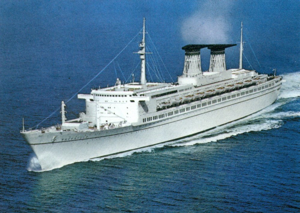
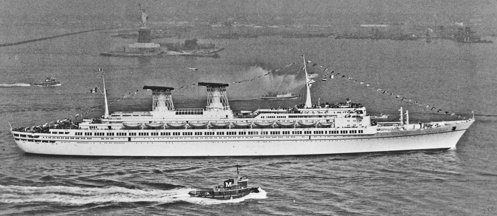
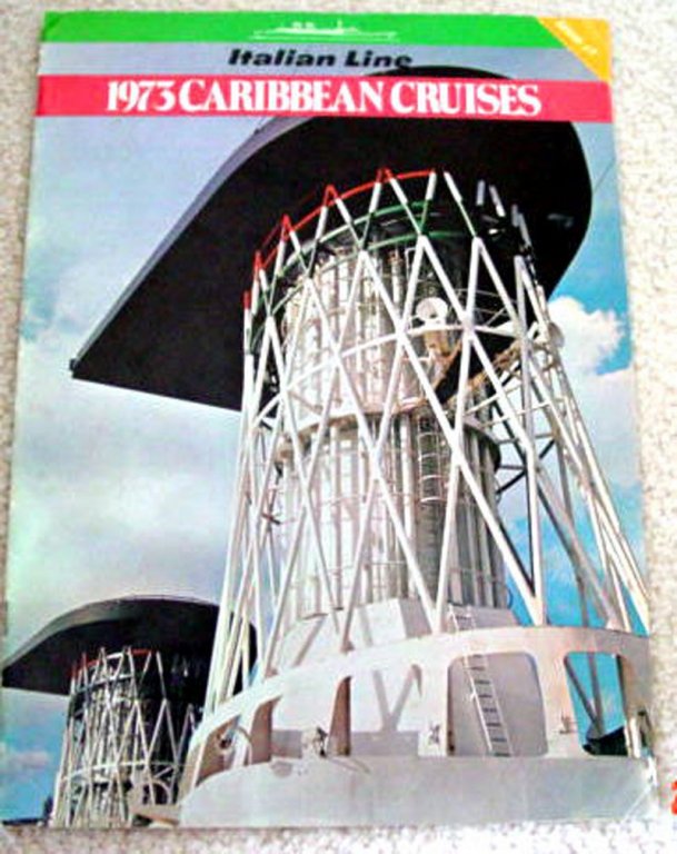
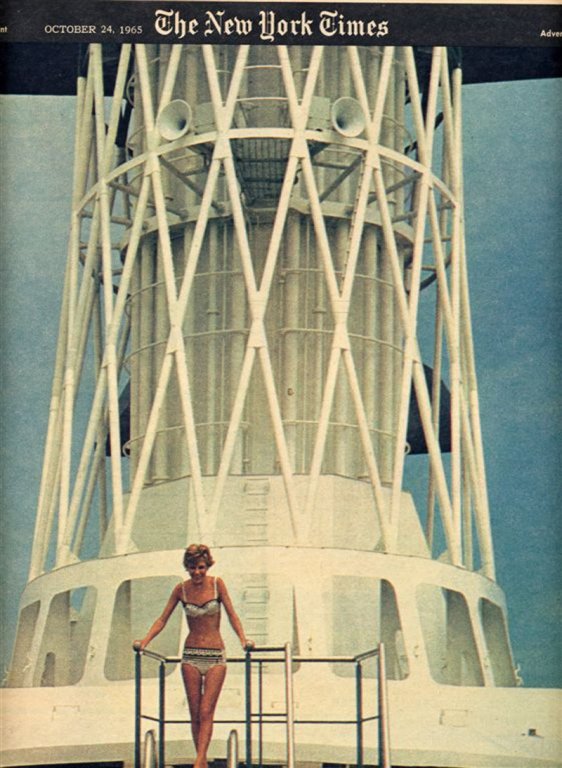
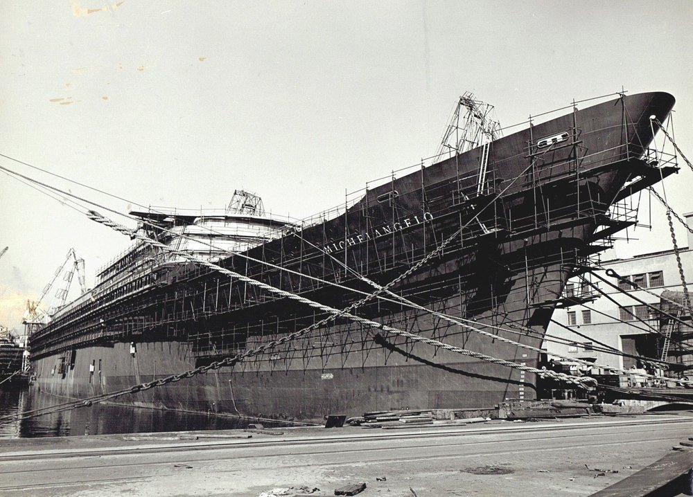
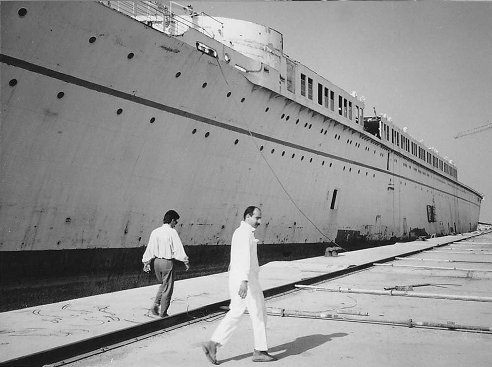
Hello all - Welcome to those of you who followed my build log of my previous ocean liner, the SS Andrea Doria. If you have not seen it, you can reach it by clicking the link below my profile, below. The Michelangelo was a slightly newer ship and sleeker in appearance. To give myself a bit more of a challenge, the model is being built to the scale of 1/350 rather than 1/200 as were my previous liner models. This means that the model's overall length is just over 31", which is a reasonable size for home display. I hope to still incorporate the same level of detail as at the larger scale, with some windows laser cut and others done with custom decals. Railings, ladders, etc. will be done in photoetched brass, and let me tell you, those pieces are tiny! The primary challenge of the build will be to replicate the cages around the funnels at this scale. The cages are one of the most visually appealing aspects of the ship, and were magnets for publicity photographs and even made it to the cover of the New York Times Magazine section. Nice shape, don't you think? As usual, my research began with trolling the internet, various books and other publications for images of the ship that would confirm and supplement the engineering drawings that would be ordered from the Italian naval archives. Out of about a thousand images some 200 were selected that were of such sufficient clarity and resolution to be useful. The covered almost every aspect of the ship, from her construction in the Anseldo Shipyards in Genoa to her ultimate end in the Pakistani breakers yard in 1991 Next time I will go into the process that I used to go from the plans to a laid-up basswood hull. Until then, be well Dan
- 287 replies
-
- 14
-
-
- michelangelo
- ocean liner
- (and 1 more)
-
Hi Tom - Your Connie is coming along very nicely. Really clean work on the tops. One quick suggestion - if you are planning to install crowsfeet from the tops to the stays, you should drill the holes now before installing the tops. It is a real bear to get them drilled neatly afterwards. Will we see her in New London at the Joint Clubs Conference at the end of April? Dan
- 1,350 replies
-
- 2
-
-
- constitution
- model shipways
- (and 1 more)
-
Hi Marc - Fascinating discussion. You are clearly doing your homework, and then some. Have you drawn an expansion of the layout from the top (plan view) for the three decks where you have balconies? Figuring out a reasonable interior layout may help you with the exterior decisions - the locations of doors to the balconies, for example. You might also get an idea of how wide (deep) the balconies are. Obviously, they need to be wide enough to permit a man to walk along them between the windows and the rails. One thing you have not mentioned, probably because it has not come up yet, is that it seems to me that the central sections of the balconies are extended aft to make a larger area for sitting. and that is what is shown on the side view. Is this how you see it? I really like the added depth of the sills for the gunports and your attention to the small detail that the lower ports have deeper sills than the upper ones. Be well Dan
- 2,699 replies
-
- 2
-
-
- heller
- soleil royal
- (and 9 more)
-
Mark - A very nice example of how to merge modern technology and techniques with traditional building methods. You are on the laser cutting edge of this and I am looking forward to your future postings of your thoughts on how it all comes together. Dan
-
Hi Charlie - Coming along really nicely. Love the crisp edges and corners you are creating. On the restored ships that I have been on, where I could tell anything about the coaming joints under various layers of paint or varnish, there was no consistent height for the coaming, nor for the placement of the lock joint. Also, sometimes there was a quarter-round molding around the coaming to protect the butt ends of the deck planks from rot. As for the carronade, I suspect most every foundry had its own pattern for the casting, which probably also changed over time, even within any one country. As for which of the commercial items to use, it depends on how you are going to mount it. The brass ones are drilled for a trunnion and carriage mount, like most cannon. The pewter one has a lug on the bottom for a slide carriage. You will have to modify them if you want to use the non-matching style. The pewter one, I think, is the most accurate overall. The brass ones do not have a vertical breeching ring, but that horizontal 'doughnut' which I think is wrong. It looks like a part of a metal elevating screw system, although the Caldercraft plans show a wooden quoin wedge for that purpose. Hope that helps. Dan PS - what an Amazing/Hearbreaking game! Had no real rooting interest, but it certainly wasn't boring.
- 362 replies
-
- 2
-
-
- active
- revenue cutter
- (and 1 more)
-
Hi Charlie - There are good descriptions and drawings of some carronades in both of the volumes of the NRG's Ship Modelers' Shop Notes, which I thought you had. There were a number of styles and shapes depending on the nation of origin and the year of manufacture, so you just have to pick the one that you think fits best with your ship. The article by Mark Lardas is a good start. He is a well known and respected ship modeler and author. That said, the pivot mount for your guns is not very much like the slide mounts for broadside carronades. You can see the one I did for USS Oneida (1812) when you come to the meeting tonight. It was taken from Chapelle's description in History of the American Sailing Navy. I cannot locate the exact page at the moment. Then there are scale drawings in three perspective views in any Anatomy of the Ship book which examines a ship that carried carronades. All drawings are labeled with numbered parts, so you can see that your 'hook' is actually a 'breaching ring' and your 'lump' is part of the sighting and aligning system. Really looking forward to seeing how your laser cut parts come out. Dan
- 362 replies
-
- 5
-
-
- active
- revenue cutter
- (and 1 more)
-
Hi Charlie - Just got a chance to review the last page or so. Wow, lots of thought going into your artistic choices. The experiments on wood species and finish will be referred to often, I'm sure. They certainly would make for a top notch Shop Note in the Journal. My two cents on some of your questions and techniques that worked for me: - both 'naked' and finished holly look good, but look best if they match in tone the surrounding bulwarks and deck pieces. In your last two photos both decks look good, although one is much lighter than the other. But both sit well with the rest of the model. - If you are finishing the deck, just make sure that the ink in your marker is not dissolved by the finish you use. I had to scrap a whole deck once before I learned that lesson. - the planking diagram you are using is very good, but has a small problem. Just ahead of the main hatch there are butt joints indicated that are about a foot from the coaming. No shipyard would have created an extra leakage point, just used a longer plank. Don't be rigidly locked to the drawing if it does not match common woodworking sense. - if you are scoring the butt joints into the veneer, try highlighting the groove with a sharp pencil. This has to be sealed to prevent smearing, so it will not work if you are leaving the deck unfinished. I have used a similar technique for the plank fasteners using a dull mechanical pencil. I hold it vertically on the desired spot and give it a quick spin, making a round mark. Really looking forward to seeing how your models evolve. Dan
- 362 replies
-
- 6
-
-
- active
- revenue cutter
- (and 1 more)
-
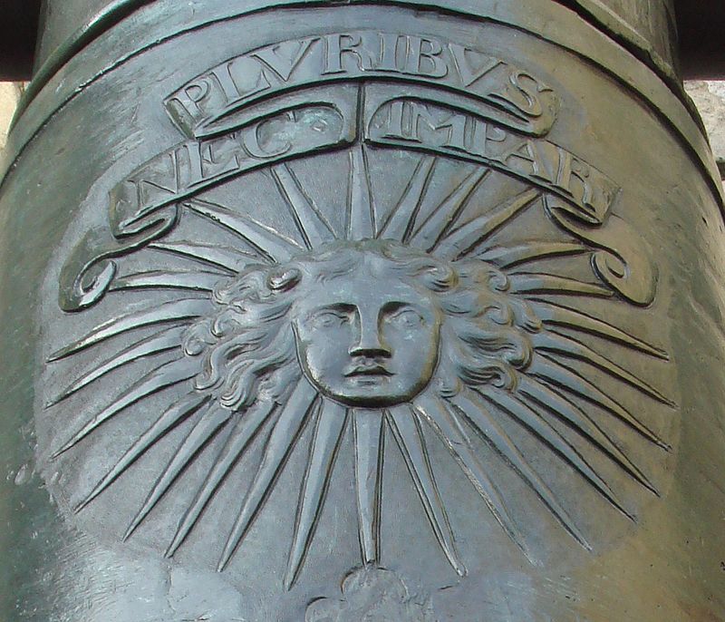
Here is an illustration of it, and how it was rendered on a cannon. Dan

- 2,699 replies
-
- 6
-
-
- heller
- soleil royal
- (and 9 more)
-
Hi Marc - The scroll looks great, but Louis XIV already has a motto, "Nec Pluribus Impar", which is said to be quite difficult to translate. The general meaning is along the lines of "Not Unequal to Many", implying that he was the equal of many suns in his power and illumination. As for placement, I have never seen any decoration across the square tuck portion of the stern. Possibly because it would be really subject to destruction from any following sea. Maybe it could go across the railing of the lowest gallery of the stern cabins? Dan
- 2,699 replies
-
- 2
-
-
- heller
- soleil royal
- (and 9 more)
-
Hi Marc - Just stopped bye when you posted so let me wade in first. I agree with you that the top hamper would have been removed during battle,. Certainly during the period that you are interested in, and especially for the large ships of the line. They were slow and wallowing, and once into the line maneuvering was not part of the battle plan. I have the impression that it was actively discouraged, although I don't recall a specific example. This was why having the weather gauge was so important. Only much later, with Nelson and a few others, do the tactics change to a more fluid attack. Single ship actions between frigates and other mid-sized ships were different, and it might me interesting to check if they are shown with top hamper during battle. I'll keep an eye out. Happy Holidays to you and yours. Dan
- 2,699 replies
-
- 4
-
-
- heller
- soleil royal
- (and 9 more)
-
Hi Nils - Really fine work on the anchor machinery. Where did you source the stud-link chain? Or did you make it yourself? Love the warning sign. Dan
- 2,625 replies
-
- 6
-
-
- kaiser wilhelm der grosse
- passenger steamer
- (and 1 more)
-
Hi Marc - The more time I spend on the drawing/planning/thinking part of a project, the less time I spend rebuilding what I did not sufficiently think/plan/draw the first time around. You are certainly putting in your due diligence. The building should go so much smoother for the work done now. As for the window, the baroque embellishments look really good. But is it really a window? If it is the one I am thinking of, the placement and the fact that there are a line of them makes me think that they are gunports on the quarterdeck. Dan
- 2,699 replies
-
- 2
-
-
- heller
- soleil royal
- (and 9 more)
-
Charlie - The planking looks great. Nice even tapers and a fair run back to midships. Congratulations. Dan
- 362 replies
-
- 3
-
-
- active
- revenue cutter
- (and 1 more)
-
Hi Charlie - The stands came out nicely. They will support your models through all the tribulations yet to come. But you also need a way to hold and support the hull upside down when you are doing the planking. The easiest way I found for a small hull is to temporarily screw a square cut "handle", maybe 1" x 1", down the centerline of the deck. You can position the screws so the holes will later be covered by deck houses or other fittings. Then the model can be flipped over and the handle held in a vise. I see you have a Keel Klamper device, which may work for you. As far as planking widths, here is another wrinkle - the plank that runs along the keel is called the 'garboard strake' and is wider, about 1 1/2 times the width of the majority of the hull planks. The next plank up, known as the 'first broad strake' is also wider than hull planks, but not quite as wide as the garboard. This is rarely seen on a model, especially since most are either painted below the waterline to simulate the tarry stuff used to combat teredo worm, or the hull is coppered, covering everything. Not an important nit to pick, but you seem to want to get the details right, a mindset that I applaud. I am enjoying watching your progress. Dan
- 362 replies
-
- 6
-
-
- active
- revenue cutter
- (and 1 more)