


shipmodel
-
Posts
908 -
Joined
-
Last visited
Reputation Activity
-

 shipmodel got a reaction from uss frolick in SS Mayaguez c.1975 by shipmodel - FINISHED - scale 1/16" = 1' (1:192) - Dan Pariser
SS Mayaguez (c. 1975), scale 1:192 by Dan Pariser
Hi to everyone who followed me from the build log of the restoration of the bone and ivory POW model to this one, and hello to any modeler who might be interested in a completely different subject using completely different materials. I hope that I can make this build log as informative as the last one.
The subject here is the SS Mayaguez, an American container ship that was involved in a famous incident of piracy at sea. On May 12, 1975, about a week after the fall of Saigon, and a month after the fall of Cambodia (renamed Kampuchea) to the communist Khmer Rouge, Mayaguez was en route from Hong Kong on what was to be a routine voyage. Travelling through a disputed area, the ship was accosted by a gunboat flying a red flag which fired machine guns and a rocket over the bow. The ship stopped and was taken over by Kampuchean sailors. The crew were captured and removed from the ship. Upon learning of this, American planes were scrambled from nearby bases and photographs of the ship and gunboats were taken as hurried plans were made to recapture the ship and free the crew.
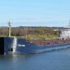
SS Mayaguez was launched in April 1944 as SS White Falcon, a Maritime Commission C2-S-AJ1 freighter built in North Carolina. Type C2 ships were all-purpose cargo ships with five holds, but were remarkable for their versatility, speed and fuel economy. U.S. shipyards built 328 of them from 1939 to 1945 similar to this one shown in wartime camouflage.
After her service in World War II the ship was sold to Grace Line and carried coffee from South America. In 1960 she was converted into one of the first all-container ships, with a capacity of 382 boxes below deck plus 96 on deck.
To do this she was lengthened from 459 feet to 504 by adding a midships section and widened from 63 feet to 74 by adding oddly shaped and angled sponsons on each side.
To support and level the containers on deck above the curved sheer of the hull, structures similar to railroad trestles were built. Because few ports at the time had equipment built to handle containers the ship was also fitted with two rolling cranes, one forward of the superstructure and one aft, riding on rails mounted on those levelling trestles.
The cranes had wings that could hinge up to shuttle the containers out and over the docks and onto or off of waiting trucks or trains. In this photo the wings are up and extended, while they are down in the prior one. Notice that these are extended even though they are over the water side. I suppose that this was done to help balance the ship during loading operations.
In 1964 the ship was sold to the container line Sea-Land Service and renamed SS Mayaguez after the city in Puerto Rico. In 1967 she began regular container service in support of US combat forces in Vietnam and Southeast Asia. After the US withdrawal in 1973 the Mayaguez began sailing a commercial route between Hong Kong, Thailand and Singapore. It was on one of those runs that she was captured.
I was recently asked to build a waterline model on an ocean base commemorating the event for the U.S. Merchant Marine Academy museum in their preferred scale of 1/16” = 1’, or 1:192. As usual, I scoured the internet for plans and images of the ship so my model could be as accurate as possible. Unfortunately, I could not find any plans of the ship available from after its conversion to work from. I even contacted Sea-Land, without success, so the project became mostly an exercise in photo interpretation.
I found many images, most of which were of only moderate resolution, but all of which gave me some information or viewpoint that let me develop the details. I did locate a plan of a generic C2 cargo ship which gave me the general outline of the original ship.
I then located two photos taken by the US Air Force during and just after the incident that were of high resolution and taken from almost exactly overhead on the centerline. These gave me the outline of the expanded deck which could be combined with the C2 plan and photos of the sponsons to give me a good idea of the final shape of the hull.
Armed with this information I could lay out the lifts that I would need to build the hull. I first used Photoshop to resize both the C2 plans and the overhead photos to match the overall dimensions of the model (504 feet x 12 / 192 = 31.5 inches). On the C2 plans I marked out ½” lifts from below the waterline to the beginning of the upward curve of the sheer of the ship. A 5/8” tapered wedge at the bow and a similar 3/8” wedge at the stern gave me the basic curve of the deck.
½” basswood sheets were cut for the lower lifts according to the plans, then attached with wood glue colored black with acrylic paint. This gave me indelible horizontal guides to guide the shaping process, especially the waterline. Here the bow has been assembled and the 5/8” sheer wedge has been planed to shape and attached. The wedge was sanded to a smooth shallow curve and the 1/8” deck piece was cut a bit oversize to allow for adjustment, then secured.
At the stern the same process was used, just with a flatter wedge. The raised fore and stern castles were cut to shape from the photo and attached, fairing them to the lower hull.
The hardest part of the hull construction was to fashion the sponsons, which had to match the overhang of the deck piece, fit snugly against the curves of the original C2 hull, and match the shapes seen in the photos of the sides of the hull. They were built up in several pieces, being pinned to the hull temporarily with wooden dowels during shaping. Several attempts had to be made to get everything to fit, and even here in this photo of my third stern sponson there were problems (notice how the bottom edge of the aft piece is curved and not straight) and the piece was discarded.
Eventually I learned from my mistakes and the sponsons took on the shapes that I wanted. Once that was done the entire hull got a thin coating of plaster of paris to seal the wood and fill the larger joints.
This layer was mostly sanded off to give me a smooth surface for the first of half a dozen primer coats. These were individually sanded as well until any small defects were filled and smooth. The hull then got a color coat of rust resistant red paint below the waterline and a navy blue coat above, as seen in the few color photos. The deck was also filled and sanded, but left with just the primer coat.
While this was going on I was also fiddling with the layout and construction of the superstructure. That will be the subject of the next installment.
Until then, be well.
Dan
-

 shipmodel got a reaction from CiscoH in SS Mayaguez c.1975 by shipmodel - FINISHED - scale 1/16" = 1' (1:192) - Dan Pariser
Hello again –
Thank you all for your well wishes on my health. I do seem to be recovering, slowly, on the long covid front. I can mostly sleep at night without coughing or sitting up, but it does come back with a vengeance from time to time. The silver lining to this cloud is that I can get more done during the insomniac periods. Hence, this post somewhat quickly after the last one.
As in most builds, especially with modern ships, I work on several sub-projects at the same time. While the superstructure was still being finished I turned to the containers on deck. In an earlier build of a container ship model for the museum, the El Faro (build log soon to be written), I had researched these ‘intermodal containers’. I found that ninety percent of the global container fleet are closed rectangular boxes, almost all 8 feet (2.44 m) wide, and of either 20 or 40 feet (6.10 or 12.19 m) standard length, and with a standard height of 8 feet 6 inches (2.59m) as defined by the International Organization for Standardization (ISO) regulation 668:2020.
The height and width of the containers on the Mayaguez seem to fit these dimensions in this photograph taken just after the recapture of the ship. You can also see that they are stacked in sets of three, and in two layers.
However, to my surprise, when I used Photoshop rulers and scaled out the length of the containers from the overhead shots, they measured out to only 35 feet long, a size that I had not encountered before.
Back to the books! After a good deal of reading I located a single sentence in “An Act of Piracy, The Seizure of the American-flag Merchant Ship Mayaguez in 1975” by Gerald Reminick. There he says that when Grace Line sold its Santa Eliana, ex-White Falcon, to Sea-Land Service in 1965 the ship was sent for a second conversion where the container cells on board were enlarged to accommodate the new 35 ft. containers. It was Sea-Land that changed her name to Mayaguez later that year.
Now that I had confirmation of the correct sizes, I had to determine the details of their structures. Modern containers have sides of pressed metal with the corrugations quite close together, like those in a cardboard box. Instead, the 1965 containers had smooth sides reinforced with square section battens spaced much further apart. In the detailed photographs of the Mayaguez containers only 16 of these battens can be counted. With the two ends there are 17 panels, so in 35 feet the battens must be close to 2 feet apart.
I tried a number of ways to create this look. I started with looking around for what was commercially available, but none of the Evergreen Plastics sheets were close. Neither their railroad car, passenger car or siding extrusions were close to what I needed. Then I tried making them myself, gluing 0.01” square strips to smooth plastic sheets at a spacing of 1/8”, but I could never keep the long strips straight. If I did it by eye, they wandered all over before the glue dried. If I held them against a metal or wood straightedge, then they got glued to the straightedge. This happened even when I used thin glue meant just for plastic, which melted the plastic, but the melted plastic then would attach again to the straightedge. I tried cutting narrow parallel channels with a thin blade in the Preac table saw, to be filled with thin strips, but the depths could not be cut consistently.
Ultimately I decided to compromise on the look a little in order to get it done. Evergreen has a product which represents a metal roof with batten supports (#4521). It comes as a sheet 0.04” thick with channels 0.015” deep set 3/16” apart. These channels are to be filled with thin strips 0.01” x 0.03” which are supplied with the sheet. Doing this is a tedious process, to say the least. Each strip had to be turned on edge and set into the start of the channel. It was tacked there with a small drop of Tamiya extra thin plastic glue (which is mostly acetone), which welds the strip to the sheet. Then the rest of the strip, still set upright, had to be fed into the length of the channel and glued there.
There was a distinct learning curve and a good bit of wastage of these expensive sheets before I got the hang of it. The final product looked very much like the photos of the container sides, although the spacing of the battens was 3’ rather than 2’ apart. As mentioned before – GEFGW.
With the strips in place the six pieces for each rectangular box had to be designed and cut. Each had to be sized to compensate for the thickness of the material so that the final assembled size was 0.50” x 0.53” x 2.19” (8’ x 8.5’ x 35’). I also had to compensate for the various edging strips that were added to make up the look of the corners of the boxes. Once all the calculations were done, the pieces for the sides were parted off the sheet on the Preac.
These ribbed side pieces then had to have edging around all four sides, made from strips 0.02” x 0.06”. The final piece is shown in the insert below.
The final components are shown below. These are the ones needed for a set of three containers. To minimize the number of ribbed pieces only the outside sides, ends and tops of the containers are ribbed. Where the side will not be seen it is not ribbed.
The first step to assemble each container was to set a side piece against a top piece using wood blocks to hold them perpendicular. Thin plastic glue was fed along the seam and held until it was hard.
Turning it over the matching ribs can be seen.
The second side is attached in a similar manner, but using a specially cut wood spacer to keep the sides parallel. I marked it in blue so I would not throw it out by mistake.
Each end was installed using the spacer block again to make sure it was vertical.
Finally the open box was turned over and laid on the base, which had been cut a bit oversize. When the glue was dry the excess was trimmed and the container complete.
To give some differentiation and interest to the containers they were randomly painted in three different metallic colors: dark steel, flat antique nickel, and titanium silver.
Placards with the Sea-Land logo and name were created in my computer and printed out onto thin acid-free paper. Two different styles for the larger side labels and small ones for the ends as seen in the photographs.
With the labels attached the containers were attached in sets of three to an underlying base plate and stacked on deck to judge how well they fit.
Here they all are, 8 stacks of 12 containers each.
Sitting here you can see the curve of the sheer of the deck. Without some levelling structures the cranes would not have been able to move them consistently. Those structures will be covered in the next installment.
Thank you all for following along and for your interest and comments.
Be well
Dan
-
 shipmodel got a reaction from lmagna in SS Mayaguez c.1975 by shipmodel - FINISHED - scale 1/16" = 1' (1:192) - Dan Pariser
Hello again –
Thank you all for your well wishes on my health. I do seem to be recovering, slowly, on the long covid front. I can mostly sleep at night without coughing or sitting up, but it does come back with a vengeance from time to time. The silver lining to this cloud is that I can get more done during the insomniac periods. Hence, this post somewhat quickly after the last one.
As in most builds, especially with modern ships, I work on several sub-projects at the same time. While the superstructure was still being finished I turned to the containers on deck. In an earlier build of a container ship model for the museum, the El Faro (build log soon to be written), I had researched these ‘intermodal containers’. I found that ninety percent of the global container fleet are closed rectangular boxes, almost all 8 feet (2.44 m) wide, and of either 20 or 40 feet (6.10 or 12.19 m) standard length, and with a standard height of 8 feet 6 inches (2.59m) as defined by the International Organization for Standardization (ISO) regulation 668:2020.
The height and width of the containers on the Mayaguez seem to fit these dimensions in this photograph taken just after the recapture of the ship. You can also see that they are stacked in sets of three, and in two layers.
However, to my surprise, when I used Photoshop rulers and scaled out the length of the containers from the overhead shots, they measured out to only 35 feet long, a size that I had not encountered before.
Back to the books! After a good deal of reading I located a single sentence in “An Act of Piracy, The Seizure of the American-flag Merchant Ship Mayaguez in 1975” by Gerald Reminick. There he says that when Grace Line sold its Santa Eliana, ex-White Falcon, to Sea-Land Service in 1965 the ship was sent for a second conversion where the container cells on board were enlarged to accommodate the new 35 ft. containers. It was Sea-Land that changed her name to Mayaguez later that year.
Now that I had confirmation of the correct sizes, I had to determine the details of their structures. Modern containers have sides of pressed metal with the corrugations quite close together, like those in a cardboard box. Instead, the 1965 containers had smooth sides reinforced with square section battens spaced much further apart. In the detailed photographs of the Mayaguez containers only 16 of these battens can be counted. With the two ends there are 17 panels, so in 35 feet the battens must be close to 2 feet apart.
I tried a number of ways to create this look. I started with looking around for what was commercially available, but none of the Evergreen Plastics sheets were close. Neither their railroad car, passenger car or siding extrusions were close to what I needed. Then I tried making them myself, gluing 0.01” square strips to smooth plastic sheets at a spacing of 1/8”, but I could never keep the long strips straight. If I did it by eye, they wandered all over before the glue dried. If I held them against a metal or wood straightedge, then they got glued to the straightedge. This happened even when I used thin glue meant just for plastic, which melted the plastic, but the melted plastic then would attach again to the straightedge. I tried cutting narrow parallel channels with a thin blade in the Preac table saw, to be filled with thin strips, but the depths could not be cut consistently.
Ultimately I decided to compromise on the look a little in order to get it done. Evergreen has a product which represents a metal roof with batten supports (#4521). It comes as a sheet 0.04” thick with channels 0.015” deep set 3/16” apart. These channels are to be filled with thin strips 0.01” x 0.03” which are supplied with the sheet. Doing this is a tedious process, to say the least. Each strip had to be turned on edge and set into the start of the channel. It was tacked there with a small drop of Tamiya extra thin plastic glue (which is mostly acetone), which welds the strip to the sheet. Then the rest of the strip, still set upright, had to be fed into the length of the channel and glued there.
There was a distinct learning curve and a good bit of wastage of these expensive sheets before I got the hang of it. The final product looked very much like the photos of the container sides, although the spacing of the battens was 3’ rather than 2’ apart. As mentioned before – GEFGW.
With the strips in place the six pieces for each rectangular box had to be designed and cut. Each had to be sized to compensate for the thickness of the material so that the final assembled size was 0.50” x 0.53” x 2.19” (8’ x 8.5’ x 35’). I also had to compensate for the various edging strips that were added to make up the look of the corners of the boxes. Once all the calculations were done, the pieces for the sides were parted off the sheet on the Preac.
These ribbed side pieces then had to have edging around all four sides, made from strips 0.02” x 0.06”. The final piece is shown in the insert below.
The final components are shown below. These are the ones needed for a set of three containers. To minimize the number of ribbed pieces only the outside sides, ends and tops of the containers are ribbed. Where the side will not be seen it is not ribbed.
The first step to assemble each container was to set a side piece against a top piece using wood blocks to hold them perpendicular. Thin plastic glue was fed along the seam and held until it was hard.
Turning it over the matching ribs can be seen.
The second side is attached in a similar manner, but using a specially cut wood spacer to keep the sides parallel. I marked it in blue so I would not throw it out by mistake.
Each end was installed using the spacer block again to make sure it was vertical.
Finally the open box was turned over and laid on the base, which had been cut a bit oversize. When the glue was dry the excess was trimmed and the container complete.
To give some differentiation and interest to the containers they were randomly painted in three different metallic colors: dark steel, flat antique nickel, and titanium silver.
Placards with the Sea-Land logo and name were created in my computer and printed out onto thin acid-free paper. Two different styles for the larger side labels and small ones for the ends as seen in the photographs.
With the labels attached the containers were attached in sets of three to an underlying base plate and stacked on deck to judge how well they fit.
Here they all are, 8 stacks of 12 containers each.
Sitting here you can see the curve of the sheer of the deck. Without some levelling structures the cranes would not have been able to move them consistently. Those structures will be covered in the next installment.
Thank you all for following along and for your interest and comments.
Be well
Dan
-
 shipmodel reacted to KeithAug in SS Mayaguez c.1975 by shipmodel - FINISHED - scale 1/16" = 1' (1:192) - Dan Pariser
Very nice superstructure Dan, but god only knows how you manage to interpret those fuzzy images. It would do my head in.
-
 shipmodel got a reaction from Mirabell61 in SS Mayaguez c.1975 by shipmodel - FINISHED - scale 1/16" = 1' (1:192) - Dan Pariser
Hello again to all –
Thanks for all the likes and comments. Keep them coming.
Sorry for the long delay since my last post. I have been fighting a long covid problem that gives me bronchitis which makes me cough, especially at night, so I am having a lot of trouble sleeping. Also I have had cataract surgery on both eyes, which has interfered with writing this blog.
But enough about me – back to the model.
At the end of the last segment I had completed the basic structure of the hull and was proceeding to work out the superstructure. This began, as with the rest of the model, with a careful examination of the photographs of the ship. Fortunately there were a few images of high resolution like this one of the entire ship.
Once enlarged I got a good, if a little fuzzy, picture of the 5 decks and deck houses of the superstructure. I was able to tease out some sense of the complex shapes of the various decks and overhangs. Porthole, door, and stairway locations can be seen, as well as the fact that the top deck house is taller than all the others.
In this slightly clearer image I could start the actual analysis of the dimensions and relationships of the shapes that can be seen. I started with the assumption that the original superstructure footprint had been retained, which is the lowest deck house with the curved fillets on either side. Then, when the hull was widened by 8 feet on each side, some changes were made. The supports for the lifeboat davits had to be built out and supported by pillars reaching to the outer edge of the deck. There is an overhang to the right of the lifeboat that extends to the new deck edge and is supported by three diagonal braces. The bridge wings had to be extended, and a number of other small details all had to be changed.
These images and analysis was integrated with the information from the overhead photos of the ship taken during the incident and rescue, such as this one from just after the recapture.
The image was enlarged and straightened out to give a top view that could be worked with. Always being aware that the image is not precisely taken from directly overhead, I could make out many more details, such as the stairways marked with the red arrows. Hours of staring at these images, individually and collectively, were needed to determine what the various elements and details were. I am still not 100% sure of all of them, and even where I am sure of the shape of things, I am not sure of their purpose. But since this is for the US Merchant Marine Academy, it is good enough for government work.
Other images which were not full pictures of the decks and deck houses also informed a number of details of railings, stairways, overhangs, supports, etc. Here, for example, is one of the Marines taking control of the ship. I would not have seen the tall ventilator/filter under the stairs at the side of the bridge except for this picture.
So, taking all the information in hand, I laid out the shape of the lowest deck house over the top image.
Using this as my basic starting point I laid on the shapes of the stairway platforms and lifeboat davit supports to the first level. Then using the relationships seen in the photos, I drew on the shapes of the second and third decks, deck houses, and overhangs in contrasting colors, giving this image.
Based on these drawings I cut ½” planks of basswood to the shapes of the deck houses (less 0.04” all around) and sheathed them with 0.02” styrene (restoring the full sizes). The decks were cut to the full size of the deck houses and painted grey before being edged with styrene. This gave a pleasing delineation to the decks, which can be seen in the photos. The edges extended just a bit above the deck level, making a lip that anchored the photoetched railings when they were added later. Portholes are the brass dollhouse electric circuit pieces, while the handrails are 0.015” round rod. Here the superstructure stack is about half done, with all the upper details still to be done.
Here is an enlarged shot of some of the details. Notice the diagonal supports for the overhangs of the second deck and bridge wing. The railings and stairways are photoetched brass from Gold Medal Models’ ocean liner set. It is expensive, but makes for a very convincing impression when painted, folded and installed.
The railings come in long frets four scale feet tall (1/4”) with horizontal rails numbering from one to five to be used as needed. The photos of the ship show that the railings mostly have three rails, so these were the frets that were used. They were spray painted gloss white before being cut apart. Unfortunately the paint was a bit brittle, so it chipped off when bent, as can be seen in the last photo, but that was easily touched up later.
The stairways come as part of a larger fret with hooks, steering wheels, etc. They have a central length of steps flanked by angled wings for the side railings. They come in three different lengths. Mostly the middle length was used, but occasionally the short or long ones were needed for a particular location. Small adjustments to length were made by trimming the bottom of the stairways.
The basic stairway is made by bending up the wings of the piece to form the railings at either side of the steps (left image). But this is meant for use on the ocean liners, so it is wider and less steep than the stairways on merchant ships. To make them steeper the railings are pressed down towards the steps till the supporting posts are vertical when the stairs are at the steeper angle (middle image). Where the stairs had to be narrow, one side railing and some of the width of the steps was cut off and the stairs supported by an added strip of styrene (right image).
Work continued on the superstructure with detail added as they were identified in the photos. Note the cross supports between the lower and upper bridge wings and the fact that the front facing of the upper bride wing is taller at the bridge house than it is at the outer end. The funnel has now been sheathed and is set in place so I could determine the location and size of the many details on the upper decks.
While this analysis and work on the superstructure continued I was also starting to puzzle out the size and shape of the 96 containers that had to be installed on deck, and how to build them in a reasonably efficient manner. This will be the topic of the next segment.
Till then, may your health be better than mine.
Dan
-
 shipmodel got a reaction from Rick310 in SS Mayaguez c.1975 by shipmodel - FINISHED - scale 1/16" = 1' (1:192) - Dan Pariser
Hello again to all –
Thanks for all the likes and comments. Keep them coming.
Sorry for the long delay since my last post. I have been fighting a long covid problem that gives me bronchitis which makes me cough, especially at night, so I am having a lot of trouble sleeping. Also I have had cataract surgery on both eyes, which has interfered with writing this blog.
But enough about me – back to the model.
At the end of the last segment I had completed the basic structure of the hull and was proceeding to work out the superstructure. This began, as with the rest of the model, with a careful examination of the photographs of the ship. Fortunately there were a few images of high resolution like this one of the entire ship.
Once enlarged I got a good, if a little fuzzy, picture of the 5 decks and deck houses of the superstructure. I was able to tease out some sense of the complex shapes of the various decks and overhangs. Porthole, door, and stairway locations can be seen, as well as the fact that the top deck house is taller than all the others.
In this slightly clearer image I could start the actual analysis of the dimensions and relationships of the shapes that can be seen. I started with the assumption that the original superstructure footprint had been retained, which is the lowest deck house with the curved fillets on either side. Then, when the hull was widened by 8 feet on each side, some changes were made. The supports for the lifeboat davits had to be built out and supported by pillars reaching to the outer edge of the deck. There is an overhang to the right of the lifeboat that extends to the new deck edge and is supported by three diagonal braces. The bridge wings had to be extended, and a number of other small details all had to be changed.
These images and analysis was integrated with the information from the overhead photos of the ship taken during the incident and rescue, such as this one from just after the recapture.
The image was enlarged and straightened out to give a top view that could be worked with. Always being aware that the image is not precisely taken from directly overhead, I could make out many more details, such as the stairways marked with the red arrows. Hours of staring at these images, individually and collectively, were needed to determine what the various elements and details were. I am still not 100% sure of all of them, and even where I am sure of the shape of things, I am not sure of their purpose. But since this is for the US Merchant Marine Academy, it is good enough for government work.
Other images which were not full pictures of the decks and deck houses also informed a number of details of railings, stairways, overhangs, supports, etc. Here, for example, is one of the Marines taking control of the ship. I would not have seen the tall ventilator/filter under the stairs at the side of the bridge except for this picture.
So, taking all the information in hand, I laid out the shape of the lowest deck house over the top image.
Using this as my basic starting point I laid on the shapes of the stairway platforms and lifeboat davit supports to the first level. Then using the relationships seen in the photos, I drew on the shapes of the second and third decks, deck houses, and overhangs in contrasting colors, giving this image.
Based on these drawings I cut ½” planks of basswood to the shapes of the deck houses (less 0.04” all around) and sheathed them with 0.02” styrene (restoring the full sizes). The decks were cut to the full size of the deck houses and painted grey before being edged with styrene. This gave a pleasing delineation to the decks, which can be seen in the photos. The edges extended just a bit above the deck level, making a lip that anchored the photoetched railings when they were added later. Portholes are the brass dollhouse electric circuit pieces, while the handrails are 0.015” round rod. Here the superstructure stack is about half done, with all the upper details still to be done.
Here is an enlarged shot of some of the details. Notice the diagonal supports for the overhangs of the second deck and bridge wing. The railings and stairways are photoetched brass from Gold Medal Models’ ocean liner set. It is expensive, but makes for a very convincing impression when painted, folded and installed.
The railings come in long frets four scale feet tall (1/4”) with horizontal rails numbering from one to five to be used as needed. The photos of the ship show that the railings mostly have three rails, so these were the frets that were used. They were spray painted gloss white before being cut apart. Unfortunately the paint was a bit brittle, so it chipped off when bent, as can be seen in the last photo, but that was easily touched up later.
The stairways come as part of a larger fret with hooks, steering wheels, etc. They have a central length of steps flanked by angled wings for the side railings. They come in three different lengths. Mostly the middle length was used, but occasionally the short or long ones were needed for a particular location. Small adjustments to length were made by trimming the bottom of the stairways.
The basic stairway is made by bending up the wings of the piece to form the railings at either side of the steps (left image). But this is meant for use on the ocean liners, so it is wider and less steep than the stairways on merchant ships. To make them steeper the railings are pressed down towards the steps till the supporting posts are vertical when the stairs are at the steeper angle (middle image). Where the stairs had to be narrow, one side railing and some of the width of the steps was cut off and the stairs supported by an added strip of styrene (right image).
Work continued on the superstructure with detail added as they were identified in the photos. Note the cross supports between the lower and upper bridge wings and the fact that the front facing of the upper bride wing is taller at the bridge house than it is at the outer end. The funnel has now been sheathed and is set in place so I could determine the location and size of the many details on the upper decks.
While this analysis and work on the superstructure continued I was also starting to puzzle out the size and shape of the 96 containers that had to be installed on deck, and how to build them in a reasonably efficient manner. This will be the topic of the next segment.
Till then, may your health be better than mine.
Dan
-
shipmodel reacted to KeithAug in Germania Nova 1911 by KeithAug - FINISHED - Scale 1:36 - replica of schooner Germania 1908
Thank you Keith, Steve, Andy and Brian, your comments are always welcome. Thanks to everyone for the likes.
It got very hot here for a couple of days - 40.3 deg C a few miles up the road. The workshop faces north west so it never got higher than 25 deg. A good excuse for a couple of days of boat work.
For a while I have been contemplating the sails. They are quite large requiring about 1.5 square meters of cloth. It would have been good to model them full of wind but at the size they are I don't think it will be practical to get the material to hold a curved shape. I am not planning to do all that sewing some of you are very good at. At 1/36 scale my quality of stitching would be much too heavy, so I will go with the "pencil" approach to detailing the seams. As for the material I got a sample of Silkspan (tissue) but rejected this as too flimsy. I also bought some low weight polyester (kite material) but didn't like the patten of the reinforcing threads so that was also rejected. I visited some of the local material shops to look at cotton but couldn't find anything I liked. In the end I defaulted back to what I have used before Amity sail cloth from Cornwall Model Boats. I think it is a polyester.
The size of the Amity sheets is 1m x 0.7m so I had to buy two packs. I have a little left over from the previous model and hopefully this will make up for the slight shortfall relative to my estimated requirement. I also bought a couple of rolls of ripstop tape for reinforcing edges and adding the sail reinforcing details.
I decided hot weather was the ideal time to get the sheets prepared.
I started by building a frame just a bit larger than the maximum sheet size. I made it disassembleable learning from previous mistakes.
I mounted the material on the frame stretched by elastic bands.
I then gave it a couple of coats of 1/2 and 1/2 PVA diluted with water. Ideally the material wouldn't stretch but unfortunately it does. I tried to minimise the distortion but I would have liked to have done better. It will be interesting to see how it turns out.
The 2 sheets are done and dry courtesy of our record breaking weather. It's an ill wind that blows nobody any good!!!!
-
shipmodel reacted to dvm27 in Speedwell 1752 by dvm27 (Greg Herbert) - FINISHED - Ketch Rigged Sloop
Not too much progress to note on Speedwell but the standing rigging has commenced. A photo of her in her current state is shown below. She needs twenty belaying pins. For the most part I find commercial belaying pins clunky and like to make them myself. I have seen several different techniques but they did not work particularly well in my hands so, if you have a lathe, maybe try this technique.
I discovered early in my machining, self-taught trials that in order to turn a very small diameter like the 0.020" leg of the belaying pin you have to turn against a much thicker stock or deflection occurs. In the first photo the 0.020" diameter is turned from 0.25" boxwood. The speed is high and the feed is very slow and consistent to avoid warping and deflection.
The cutting tool backed off 0.020" to form the diameter of the head of the pin.
The next step was impossible to photograph but a very fine Swiss file was used to reduce the area just above the transition.
The rest of the head was shaped with a fine Swiss file. The finished belaying pin was parted with the knife edge of the file while shaping it's curved profile. Many extras were made to insure consistency. You can see the delicate elongated shape of the pins against the illustration by David Antscherl in our Speedwell book.
The key takeaway for new home machinists is that you can turn very small diameters even in wood if you turn against a thicker stock. I can't say for sure exactly how thick but I should think at least four times the desired finished diameter.
-
shipmodel reacted to jerome in SS Mayaguez c.1975 by shipmodel - FINISHED - scale 1/16" = 1' (1:192) - Dan Pariser
Dan,
She’s coming along nicely.
sorry to hear about your Covid issues.
the Academy’s ship model fleet will be awesome soon enough.
-
shipmodel reacted to lmagna in SS Mayaguez c.1975 by shipmodel - FINISHED - scale 1/16" = 1' (1:192) - Dan Pariser
Amazing work, at least to me, considering source material you are working from. And it is also amazing that you have accompliched so much while undergoing surgery, COVID, and bronchitis/ sleep deprivation. I hope things get a little better health wise and a little easier building wise.
-
shipmodel reacted to Jim Lad in SS Mayaguez c.1975 by shipmodel - FINISHED - scale 1/16" = 1' (1:192) - Dan Pariser
Coming along nicely, Dan. An interesting commentary on the work involved in teasing out the details of fixtures and fitting from those photographs.
I trust the cataract surgery went to plan and hope you get through the long covid OK.
John
-
shipmodel reacted to mtaylor in SS Mayaguez c.1975 by shipmodel - FINISHED - scale 1/16" = 1' (1:192) - Dan Pariser
That's good news on the surgery and the recovery from COVID. She's looking a proper ship to my eye with all the details being added. Thanks for the insights on how you arrive at shapes and sizes of all those tiny bits.
-
shipmodel got a reaction from CiscoH in SS Mayaguez c.1975 by shipmodel - FINISHED - scale 1/16" = 1' (1:192) - Dan Pariser
Hello again to all –
Thanks for all the likes and comments. Keep them coming.
Sorry for the long delay since my last post. I have been fighting a long covid problem that gives me bronchitis which makes me cough, especially at night, so I am having a lot of trouble sleeping. Also I have had cataract surgery on both eyes, which has interfered with writing this blog.
But enough about me – back to the model.
At the end of the last segment I had completed the basic structure of the hull and was proceeding to work out the superstructure. This began, as with the rest of the model, with a careful examination of the photographs of the ship. Fortunately there were a few images of high resolution like this one of the entire ship.
Once enlarged I got a good, if a little fuzzy, picture of the 5 decks and deck houses of the superstructure. I was able to tease out some sense of the complex shapes of the various decks and overhangs. Porthole, door, and stairway locations can be seen, as well as the fact that the top deck house is taller than all the others.
In this slightly clearer image I could start the actual analysis of the dimensions and relationships of the shapes that can be seen. I started with the assumption that the original superstructure footprint had been retained, which is the lowest deck house with the curved fillets on either side. Then, when the hull was widened by 8 feet on each side, some changes were made. The supports for the lifeboat davits had to be built out and supported by pillars reaching to the outer edge of the deck. There is an overhang to the right of the lifeboat that extends to the new deck edge and is supported by three diagonal braces. The bridge wings had to be extended, and a number of other small details all had to be changed.
These images and analysis was integrated with the information from the overhead photos of the ship taken during the incident and rescue, such as this one from just after the recapture.
The image was enlarged and straightened out to give a top view that could be worked with. Always being aware that the image is not precisely taken from directly overhead, I could make out many more details, such as the stairways marked with the red arrows. Hours of staring at these images, individually and collectively, were needed to determine what the various elements and details were. I am still not 100% sure of all of them, and even where I am sure of the shape of things, I am not sure of their purpose. But since this is for the US Merchant Marine Academy, it is good enough for government work.
Other images which were not full pictures of the decks and deck houses also informed a number of details of railings, stairways, overhangs, supports, etc. Here, for example, is one of the Marines taking control of the ship. I would not have seen the tall ventilator/filter under the stairs at the side of the bridge except for this picture.
So, taking all the information in hand, I laid out the shape of the lowest deck house over the top image.
Using this as my basic starting point I laid on the shapes of the stairway platforms and lifeboat davit supports to the first level. Then using the relationships seen in the photos, I drew on the shapes of the second and third decks, deck houses, and overhangs in contrasting colors, giving this image.
Based on these drawings I cut ½” planks of basswood to the shapes of the deck houses (less 0.04” all around) and sheathed them with 0.02” styrene (restoring the full sizes). The decks were cut to the full size of the deck houses and painted grey before being edged with styrene. This gave a pleasing delineation to the decks, which can be seen in the photos. The edges extended just a bit above the deck level, making a lip that anchored the photoetched railings when they were added later. Portholes are the brass dollhouse electric circuit pieces, while the handrails are 0.015” round rod. Here the superstructure stack is about half done, with all the upper details still to be done.
Here is an enlarged shot of some of the details. Notice the diagonal supports for the overhangs of the second deck and bridge wing. The railings and stairways are photoetched brass from Gold Medal Models’ ocean liner set. It is expensive, but makes for a very convincing impression when painted, folded and installed.
The railings come in long frets four scale feet tall (1/4”) with horizontal rails numbering from one to five to be used as needed. The photos of the ship show that the railings mostly have three rails, so these were the frets that were used. They were spray painted gloss white before being cut apart. Unfortunately the paint was a bit brittle, so it chipped off when bent, as can be seen in the last photo, but that was easily touched up later.
The stairways come as part of a larger fret with hooks, steering wheels, etc. They have a central length of steps flanked by angled wings for the side railings. They come in three different lengths. Mostly the middle length was used, but occasionally the short or long ones were needed for a particular location. Small adjustments to length were made by trimming the bottom of the stairways.
The basic stairway is made by bending up the wings of the piece to form the railings at either side of the steps (left image). But this is meant for use on the ocean liners, so it is wider and less steep than the stairways on merchant ships. To make them steeper the railings are pressed down towards the steps till the supporting posts are vertical when the stairs are at the steeper angle (middle image). Where the stairs had to be narrow, one side railing and some of the width of the steps was cut off and the stairs supported by an added strip of styrene (right image).
Work continued on the superstructure with detail added as they were identified in the photos. Note the cross supports between the lower and upper bridge wings and the fact that the front facing of the upper bride wing is taller at the bridge house than it is at the outer end. The funnel has now been sheathed and is set in place so I could determine the location and size of the many details on the upper decks.
While this analysis and work on the superstructure continued I was also starting to puzzle out the size and shape of the 96 containers that had to be installed on deck, and how to build them in a reasonably efficient manner. This will be the topic of the next segment.
Till then, may your health be better than mine.
Dan
-
 shipmodel got a reaction from JKC27 in SS Mayaguez c.1975 by shipmodel - FINISHED - scale 1/16" = 1' (1:192) - Dan Pariser
Hello again to all –
Thanks for all the likes and comments. Keep them coming.
Sorry for the long delay since my last post. I have been fighting a long covid problem that gives me bronchitis which makes me cough, especially at night, so I am having a lot of trouble sleeping. Also I have had cataract surgery on both eyes, which has interfered with writing this blog.
But enough about me – back to the model.
At the end of the last segment I had completed the basic structure of the hull and was proceeding to work out the superstructure. This began, as with the rest of the model, with a careful examination of the photographs of the ship. Fortunately there were a few images of high resolution like this one of the entire ship.
Once enlarged I got a good, if a little fuzzy, picture of the 5 decks and deck houses of the superstructure. I was able to tease out some sense of the complex shapes of the various decks and overhangs. Porthole, door, and stairway locations can be seen, as well as the fact that the top deck house is taller than all the others.
In this slightly clearer image I could start the actual analysis of the dimensions and relationships of the shapes that can be seen. I started with the assumption that the original superstructure footprint had been retained, which is the lowest deck house with the curved fillets on either side. Then, when the hull was widened by 8 feet on each side, some changes were made. The supports for the lifeboat davits had to be built out and supported by pillars reaching to the outer edge of the deck. There is an overhang to the right of the lifeboat that extends to the new deck edge and is supported by three diagonal braces. The bridge wings had to be extended, and a number of other small details all had to be changed.
These images and analysis was integrated with the information from the overhead photos of the ship taken during the incident and rescue, such as this one from just after the recapture.
The image was enlarged and straightened out to give a top view that could be worked with. Always being aware that the image is not precisely taken from directly overhead, I could make out many more details, such as the stairways marked with the red arrows. Hours of staring at these images, individually and collectively, were needed to determine what the various elements and details were. I am still not 100% sure of all of them, and even where I am sure of the shape of things, I am not sure of their purpose. But since this is for the US Merchant Marine Academy, it is good enough for government work.
Other images which were not full pictures of the decks and deck houses also informed a number of details of railings, stairways, overhangs, supports, etc. Here, for example, is one of the Marines taking control of the ship. I would not have seen the tall ventilator/filter under the stairs at the side of the bridge except for this picture.
So, taking all the information in hand, I laid out the shape of the lowest deck house over the top image.
Using this as my basic starting point I laid on the shapes of the stairway platforms and lifeboat davit supports to the first level. Then using the relationships seen in the photos, I drew on the shapes of the second and third decks, deck houses, and overhangs in contrasting colors, giving this image.
Based on these drawings I cut ½” planks of basswood to the shapes of the deck houses (less 0.04” all around) and sheathed them with 0.02” styrene (restoring the full sizes). The decks were cut to the full size of the deck houses and painted grey before being edged with styrene. This gave a pleasing delineation to the decks, which can be seen in the photos. The edges extended just a bit above the deck level, making a lip that anchored the photoetched railings when they were added later. Portholes are the brass dollhouse electric circuit pieces, while the handrails are 0.015” round rod. Here the superstructure stack is about half done, with all the upper details still to be done.
Here is an enlarged shot of some of the details. Notice the diagonal supports for the overhangs of the second deck and bridge wing. The railings and stairways are photoetched brass from Gold Medal Models’ ocean liner set. It is expensive, but makes for a very convincing impression when painted, folded and installed.
The railings come in long frets four scale feet tall (1/4”) with horizontal rails numbering from one to five to be used as needed. The photos of the ship show that the railings mostly have three rails, so these were the frets that were used. They were spray painted gloss white before being cut apart. Unfortunately the paint was a bit brittle, so it chipped off when bent, as can be seen in the last photo, but that was easily touched up later.
The stairways come as part of a larger fret with hooks, steering wheels, etc. They have a central length of steps flanked by angled wings for the side railings. They come in three different lengths. Mostly the middle length was used, but occasionally the short or long ones were needed for a particular location. Small adjustments to length were made by trimming the bottom of the stairways.
The basic stairway is made by bending up the wings of the piece to form the railings at either side of the steps (left image). But this is meant for use on the ocean liners, so it is wider and less steep than the stairways on merchant ships. To make them steeper the railings are pressed down towards the steps till the supporting posts are vertical when the stairs are at the steeper angle (middle image). Where the stairs had to be narrow, one side railing and some of the width of the steps was cut off and the stairs supported by an added strip of styrene (right image).
Work continued on the superstructure with detail added as they were identified in the photos. Note the cross supports between the lower and upper bridge wings and the fact that the front facing of the upper bride wing is taller at the bridge house than it is at the outer end. The funnel has now been sheathed and is set in place so I could determine the location and size of the many details on the upper decks.
While this analysis and work on the superstructure continued I was also starting to puzzle out the size and shape of the 96 containers that had to be installed on deck, and how to build them in a reasonably efficient manner. This will be the topic of the next segment.
Till then, may your health be better than mine.
Dan
-
 shipmodel got a reaction from usedtosail in SS Mayaguez c.1975 by shipmodel - FINISHED - scale 1/16" = 1' (1:192) - Dan Pariser
Hello again to all –
Thanks for all the likes and comments. Keep them coming.
Sorry for the long delay since my last post. I have been fighting a long covid problem that gives me bronchitis which makes me cough, especially at night, so I am having a lot of trouble sleeping. Also I have had cataract surgery on both eyes, which has interfered with writing this blog.
But enough about me – back to the model.
At the end of the last segment I had completed the basic structure of the hull and was proceeding to work out the superstructure. This began, as with the rest of the model, with a careful examination of the photographs of the ship. Fortunately there were a few images of high resolution like this one of the entire ship.
Once enlarged I got a good, if a little fuzzy, picture of the 5 decks and deck houses of the superstructure. I was able to tease out some sense of the complex shapes of the various decks and overhangs. Porthole, door, and stairway locations can be seen, as well as the fact that the top deck house is taller than all the others.
In this slightly clearer image I could start the actual analysis of the dimensions and relationships of the shapes that can be seen. I started with the assumption that the original superstructure footprint had been retained, which is the lowest deck house with the curved fillets on either side. Then, when the hull was widened by 8 feet on each side, some changes were made. The supports for the lifeboat davits had to be built out and supported by pillars reaching to the outer edge of the deck. There is an overhang to the right of the lifeboat that extends to the new deck edge and is supported by three diagonal braces. The bridge wings had to be extended, and a number of other small details all had to be changed.
These images and analysis was integrated with the information from the overhead photos of the ship taken during the incident and rescue, such as this one from just after the recapture.
The image was enlarged and straightened out to give a top view that could be worked with. Always being aware that the image is not precisely taken from directly overhead, I could make out many more details, such as the stairways marked with the red arrows. Hours of staring at these images, individually and collectively, were needed to determine what the various elements and details were. I am still not 100% sure of all of them, and even where I am sure of the shape of things, I am not sure of their purpose. But since this is for the US Merchant Marine Academy, it is good enough for government work.
Other images which were not full pictures of the decks and deck houses also informed a number of details of railings, stairways, overhangs, supports, etc. Here, for example, is one of the Marines taking control of the ship. I would not have seen the tall ventilator/filter under the stairs at the side of the bridge except for this picture.
So, taking all the information in hand, I laid out the shape of the lowest deck house over the top image.
Using this as my basic starting point I laid on the shapes of the stairway platforms and lifeboat davit supports to the first level. Then using the relationships seen in the photos, I drew on the shapes of the second and third decks, deck houses, and overhangs in contrasting colors, giving this image.
Based on these drawings I cut ½” planks of basswood to the shapes of the deck houses (less 0.04” all around) and sheathed them with 0.02” styrene (restoring the full sizes). The decks were cut to the full size of the deck houses and painted grey before being edged with styrene. This gave a pleasing delineation to the decks, which can be seen in the photos. The edges extended just a bit above the deck level, making a lip that anchored the photoetched railings when they were added later. Portholes are the brass dollhouse electric circuit pieces, while the handrails are 0.015” round rod. Here the superstructure stack is about half done, with all the upper details still to be done.
Here is an enlarged shot of some of the details. Notice the diagonal supports for the overhangs of the second deck and bridge wing. The railings and stairways are photoetched brass from Gold Medal Models’ ocean liner set. It is expensive, but makes for a very convincing impression when painted, folded and installed.
The railings come in long frets four scale feet tall (1/4”) with horizontal rails numbering from one to five to be used as needed. The photos of the ship show that the railings mostly have three rails, so these were the frets that were used. They were spray painted gloss white before being cut apart. Unfortunately the paint was a bit brittle, so it chipped off when bent, as can be seen in the last photo, but that was easily touched up later.
The stairways come as part of a larger fret with hooks, steering wheels, etc. They have a central length of steps flanked by angled wings for the side railings. They come in three different lengths. Mostly the middle length was used, but occasionally the short or long ones were needed for a particular location. Small adjustments to length were made by trimming the bottom of the stairways.
The basic stairway is made by bending up the wings of the piece to form the railings at either side of the steps (left image). But this is meant for use on the ocean liners, so it is wider and less steep than the stairways on merchant ships. To make them steeper the railings are pressed down towards the steps till the supporting posts are vertical when the stairs are at the steeper angle (middle image). Where the stairs had to be narrow, one side railing and some of the width of the steps was cut off and the stairs supported by an added strip of styrene (right image).
Work continued on the superstructure with detail added as they were identified in the photos. Note the cross supports between the lower and upper bridge wings and the fact that the front facing of the upper bride wing is taller at the bridge house than it is at the outer end. The funnel has now been sheathed and is set in place so I could determine the location and size of the many details on the upper decks.
While this analysis and work on the superstructure continued I was also starting to puzzle out the size and shape of the 96 containers that had to be installed on deck, and how to build them in a reasonably efficient manner. This will be the topic of the next segment.
Till then, may your health be better than mine.
Dan
-
 shipmodel got a reaction from Ian_Grant in SS Mayaguez c.1975 by shipmodel - FINISHED - scale 1/16" = 1' (1:192) - Dan Pariser
Hello again to all –
Thanks for all the likes and comments. Keep them coming.
Sorry for the long delay since my last post. I have been fighting a long covid problem that gives me bronchitis which makes me cough, especially at night, so I am having a lot of trouble sleeping. Also I have had cataract surgery on both eyes, which has interfered with writing this blog.
But enough about me – back to the model.
At the end of the last segment I had completed the basic structure of the hull and was proceeding to work out the superstructure. This began, as with the rest of the model, with a careful examination of the photographs of the ship. Fortunately there were a few images of high resolution like this one of the entire ship.
Once enlarged I got a good, if a little fuzzy, picture of the 5 decks and deck houses of the superstructure. I was able to tease out some sense of the complex shapes of the various decks and overhangs. Porthole, door, and stairway locations can be seen, as well as the fact that the top deck house is taller than all the others.
In this slightly clearer image I could start the actual analysis of the dimensions and relationships of the shapes that can be seen. I started with the assumption that the original superstructure footprint had been retained, which is the lowest deck house with the curved fillets on either side. Then, when the hull was widened by 8 feet on each side, some changes were made. The supports for the lifeboat davits had to be built out and supported by pillars reaching to the outer edge of the deck. There is an overhang to the right of the lifeboat that extends to the new deck edge and is supported by three diagonal braces. The bridge wings had to be extended, and a number of other small details all had to be changed.
These images and analysis was integrated with the information from the overhead photos of the ship taken during the incident and rescue, such as this one from just after the recapture.
The image was enlarged and straightened out to give a top view that could be worked with. Always being aware that the image is not precisely taken from directly overhead, I could make out many more details, such as the stairways marked with the red arrows. Hours of staring at these images, individually and collectively, were needed to determine what the various elements and details were. I am still not 100% sure of all of them, and even where I am sure of the shape of things, I am not sure of their purpose. But since this is for the US Merchant Marine Academy, it is good enough for government work.
Other images which were not full pictures of the decks and deck houses also informed a number of details of railings, stairways, overhangs, supports, etc. Here, for example, is one of the Marines taking control of the ship. I would not have seen the tall ventilator/filter under the stairs at the side of the bridge except for this picture.
So, taking all the information in hand, I laid out the shape of the lowest deck house over the top image.
Using this as my basic starting point I laid on the shapes of the stairway platforms and lifeboat davit supports to the first level. Then using the relationships seen in the photos, I drew on the shapes of the second and third decks, deck houses, and overhangs in contrasting colors, giving this image.
Based on these drawings I cut ½” planks of basswood to the shapes of the deck houses (less 0.04” all around) and sheathed them with 0.02” styrene (restoring the full sizes). The decks were cut to the full size of the deck houses and painted grey before being edged with styrene. This gave a pleasing delineation to the decks, which can be seen in the photos. The edges extended just a bit above the deck level, making a lip that anchored the photoetched railings when they were added later. Portholes are the brass dollhouse electric circuit pieces, while the handrails are 0.015” round rod. Here the superstructure stack is about half done, with all the upper details still to be done.
Here is an enlarged shot of some of the details. Notice the diagonal supports for the overhangs of the second deck and bridge wing. The railings and stairways are photoetched brass from Gold Medal Models’ ocean liner set. It is expensive, but makes for a very convincing impression when painted, folded and installed.
The railings come in long frets four scale feet tall (1/4”) with horizontal rails numbering from one to five to be used as needed. The photos of the ship show that the railings mostly have three rails, so these were the frets that were used. They were spray painted gloss white before being cut apart. Unfortunately the paint was a bit brittle, so it chipped off when bent, as can be seen in the last photo, but that was easily touched up later.
The stairways come as part of a larger fret with hooks, steering wheels, etc. They have a central length of steps flanked by angled wings for the side railings. They come in three different lengths. Mostly the middle length was used, but occasionally the short or long ones were needed for a particular location. Small adjustments to length were made by trimming the bottom of the stairways.
The basic stairway is made by bending up the wings of the piece to form the railings at either side of the steps (left image). But this is meant for use on the ocean liners, so it is wider and less steep than the stairways on merchant ships. To make them steeper the railings are pressed down towards the steps till the supporting posts are vertical when the stairs are at the steeper angle (middle image). Where the stairs had to be narrow, one side railing and some of the width of the steps was cut off and the stairs supported by an added strip of styrene (right image).
Work continued on the superstructure with detail added as they were identified in the photos. Note the cross supports between the lower and upper bridge wings and the fact that the front facing of the upper bride wing is taller at the bridge house than it is at the outer end. The funnel has now been sheathed and is set in place so I could determine the location and size of the many details on the upper decks.
While this analysis and work on the superstructure continued I was also starting to puzzle out the size and shape of the 96 containers that had to be installed on deck, and how to build them in a reasonably efficient manner. This will be the topic of the next segment.
Till then, may your health be better than mine.
Dan
-
 shipmodel got a reaction from Canute in SS Mayaguez c.1975 by shipmodel - FINISHED - scale 1/16" = 1' (1:192) - Dan Pariser
Hello again to all –
Thanks for all the likes and comments. Keep them coming.
Sorry for the long delay since my last post. I have been fighting a long covid problem that gives me bronchitis which makes me cough, especially at night, so I am having a lot of trouble sleeping. Also I have had cataract surgery on both eyes, which has interfered with writing this blog.
But enough about me – back to the model.
At the end of the last segment I had completed the basic structure of the hull and was proceeding to work out the superstructure. This began, as with the rest of the model, with a careful examination of the photographs of the ship. Fortunately there were a few images of high resolution like this one of the entire ship.
Once enlarged I got a good, if a little fuzzy, picture of the 5 decks and deck houses of the superstructure. I was able to tease out some sense of the complex shapes of the various decks and overhangs. Porthole, door, and stairway locations can be seen, as well as the fact that the top deck house is taller than all the others.
In this slightly clearer image I could start the actual analysis of the dimensions and relationships of the shapes that can be seen. I started with the assumption that the original superstructure footprint had been retained, which is the lowest deck house with the curved fillets on either side. Then, when the hull was widened by 8 feet on each side, some changes were made. The supports for the lifeboat davits had to be built out and supported by pillars reaching to the outer edge of the deck. There is an overhang to the right of the lifeboat that extends to the new deck edge and is supported by three diagonal braces. The bridge wings had to be extended, and a number of other small details all had to be changed.
These images and analysis was integrated with the information from the overhead photos of the ship taken during the incident and rescue, such as this one from just after the recapture.
The image was enlarged and straightened out to give a top view that could be worked with. Always being aware that the image is not precisely taken from directly overhead, I could make out many more details, such as the stairways marked with the red arrows. Hours of staring at these images, individually and collectively, were needed to determine what the various elements and details were. I am still not 100% sure of all of them, and even where I am sure of the shape of things, I am not sure of their purpose. But since this is for the US Merchant Marine Academy, it is good enough for government work.
Other images which were not full pictures of the decks and deck houses also informed a number of details of railings, stairways, overhangs, supports, etc. Here, for example, is one of the Marines taking control of the ship. I would not have seen the tall ventilator/filter under the stairs at the side of the bridge except for this picture.
So, taking all the information in hand, I laid out the shape of the lowest deck house over the top image.
Using this as my basic starting point I laid on the shapes of the stairway platforms and lifeboat davit supports to the first level. Then using the relationships seen in the photos, I drew on the shapes of the second and third decks, deck houses, and overhangs in contrasting colors, giving this image.
Based on these drawings I cut ½” planks of basswood to the shapes of the deck houses (less 0.04” all around) and sheathed them with 0.02” styrene (restoring the full sizes). The decks were cut to the full size of the deck houses and painted grey before being edged with styrene. This gave a pleasing delineation to the decks, which can be seen in the photos. The edges extended just a bit above the deck level, making a lip that anchored the photoetched railings when they were added later. Portholes are the brass dollhouse electric circuit pieces, while the handrails are 0.015” round rod. Here the superstructure stack is about half done, with all the upper details still to be done.
Here is an enlarged shot of some of the details. Notice the diagonal supports for the overhangs of the second deck and bridge wing. The railings and stairways are photoetched brass from Gold Medal Models’ ocean liner set. It is expensive, but makes for a very convincing impression when painted, folded and installed.
The railings come in long frets four scale feet tall (1/4”) with horizontal rails numbering from one to five to be used as needed. The photos of the ship show that the railings mostly have three rails, so these were the frets that were used. They were spray painted gloss white before being cut apart. Unfortunately the paint was a bit brittle, so it chipped off when bent, as can be seen in the last photo, but that was easily touched up later.
The stairways come as part of a larger fret with hooks, steering wheels, etc. They have a central length of steps flanked by angled wings for the side railings. They come in three different lengths. Mostly the middle length was used, but occasionally the short or long ones were needed for a particular location. Small adjustments to length were made by trimming the bottom of the stairways.
The basic stairway is made by bending up the wings of the piece to form the railings at either side of the steps (left image). But this is meant for use on the ocean liners, so it is wider and less steep than the stairways on merchant ships. To make them steeper the railings are pressed down towards the steps till the supporting posts are vertical when the stairs are at the steeper angle (middle image). Where the stairs had to be narrow, one side railing and some of the width of the steps was cut off and the stairs supported by an added strip of styrene (right image).
Work continued on the superstructure with detail added as they were identified in the photos. Note the cross supports between the lower and upper bridge wings and the fact that the front facing of the upper bride wing is taller at the bridge house than it is at the outer end. The funnel has now been sheathed and is set in place so I could determine the location and size of the many details on the upper decks.
While this analysis and work on the superstructure continued I was also starting to puzzle out the size and shape of the 96 containers that had to be installed on deck, and how to build them in a reasonably efficient manner. This will be the topic of the next segment.
Till then, may your health be better than mine.
Dan
-

 shipmodel got a reaction from GrandpaPhil in SS Mayaguez c.1975 by shipmodel - FINISHED - scale 1/16" = 1' (1:192) - Dan Pariser
Hello again to all –
Thanks for all the likes and comments. Keep them coming.
Sorry for the long delay since my last post. I have been fighting a long covid problem that gives me bronchitis which makes me cough, especially at night, so I am having a lot of trouble sleeping. Also I have had cataract surgery on both eyes, which has interfered with writing this blog.
But enough about me – back to the model.
At the end of the last segment I had completed the basic structure of the hull and was proceeding to work out the superstructure. This began, as with the rest of the model, with a careful examination of the photographs of the ship. Fortunately there were a few images of high resolution like this one of the entire ship.
Once enlarged I got a good, if a little fuzzy, picture of the 5 decks and deck houses of the superstructure. I was able to tease out some sense of the complex shapes of the various decks and overhangs. Porthole, door, and stairway locations can be seen, as well as the fact that the top deck house is taller than all the others.
In this slightly clearer image I could start the actual analysis of the dimensions and relationships of the shapes that can be seen. I started with the assumption that the original superstructure footprint had been retained, which is the lowest deck house with the curved fillets on either side. Then, when the hull was widened by 8 feet on each side, some changes were made. The supports for the lifeboat davits had to be built out and supported by pillars reaching to the outer edge of the deck. There is an overhang to the right of the lifeboat that extends to the new deck edge and is supported by three diagonal braces. The bridge wings had to be extended, and a number of other small details all had to be changed.
These images and analysis was integrated with the information from the overhead photos of the ship taken during the incident and rescue, such as this one from just after the recapture.
The image was enlarged and straightened out to give a top view that could be worked with. Always being aware that the image is not precisely taken from directly overhead, I could make out many more details, such as the stairways marked with the red arrows. Hours of staring at these images, individually and collectively, were needed to determine what the various elements and details were. I am still not 100% sure of all of them, and even where I am sure of the shape of things, I am not sure of their purpose. But since this is for the US Merchant Marine Academy, it is good enough for government work.
Other images which were not full pictures of the decks and deck houses also informed a number of details of railings, stairways, overhangs, supports, etc. Here, for example, is one of the Marines taking control of the ship. I would not have seen the tall ventilator/filter under the stairs at the side of the bridge except for this picture.
So, taking all the information in hand, I laid out the shape of the lowest deck house over the top image.
Using this as my basic starting point I laid on the shapes of the stairway platforms and lifeboat davit supports to the first level. Then using the relationships seen in the photos, I drew on the shapes of the second and third decks, deck houses, and overhangs in contrasting colors, giving this image.
Based on these drawings I cut ½” planks of basswood to the shapes of the deck houses (less 0.04” all around) and sheathed them with 0.02” styrene (restoring the full sizes). The decks were cut to the full size of the deck houses and painted grey before being edged with styrene. This gave a pleasing delineation to the decks, which can be seen in the photos. The edges extended just a bit above the deck level, making a lip that anchored the photoetched railings when they were added later. Portholes are the brass dollhouse electric circuit pieces, while the handrails are 0.015” round rod. Here the superstructure stack is about half done, with all the upper details still to be done.
Here is an enlarged shot of some of the details. Notice the diagonal supports for the overhangs of the second deck and bridge wing. The railings and stairways are photoetched brass from Gold Medal Models’ ocean liner set. It is expensive, but makes for a very convincing impression when painted, folded and installed.
The railings come in long frets four scale feet tall (1/4”) with horizontal rails numbering from one to five to be used as needed. The photos of the ship show that the railings mostly have three rails, so these were the frets that were used. They were spray painted gloss white before being cut apart. Unfortunately the paint was a bit brittle, so it chipped off when bent, as can be seen in the last photo, but that was easily touched up later.
The stairways come as part of a larger fret with hooks, steering wheels, etc. They have a central length of steps flanked by angled wings for the side railings. They come in three different lengths. Mostly the middle length was used, but occasionally the short or long ones were needed for a particular location. Small adjustments to length were made by trimming the bottom of the stairways.
The basic stairway is made by bending up the wings of the piece to form the railings at either side of the steps (left image). But this is meant for use on the ocean liners, so it is wider and less steep than the stairways on merchant ships. To make them steeper the railings are pressed down towards the steps till the supporting posts are vertical when the stairs are at the steeper angle (middle image). Where the stairs had to be narrow, one side railing and some of the width of the steps was cut off and the stairs supported by an added strip of styrene (right image).
Work continued on the superstructure with detail added as they were identified in the photos. Note the cross supports between the lower and upper bridge wings and the fact that the front facing of the upper bride wing is taller at the bridge house than it is at the outer end. The funnel has now been sheathed and is set in place so I could determine the location and size of the many details on the upper decks.
While this analysis and work on the superstructure continued I was also starting to puzzle out the size and shape of the 96 containers that had to be installed on deck, and how to build them in a reasonably efficient manner. This will be the topic of the next segment.
Till then, may your health be better than mine.
Dan
-
 shipmodel got a reaction from yvesvidal in SS Mayaguez c.1975 by shipmodel - FINISHED - scale 1/16" = 1' (1:192) - Dan Pariser
Hello again to all –
Thanks for all the likes and comments. Keep them coming.
Sorry for the long delay since my last post. I have been fighting a long covid problem that gives me bronchitis which makes me cough, especially at night, so I am having a lot of trouble sleeping. Also I have had cataract surgery on both eyes, which has interfered with writing this blog.
But enough about me – back to the model.
At the end of the last segment I had completed the basic structure of the hull and was proceeding to work out the superstructure. This began, as with the rest of the model, with a careful examination of the photographs of the ship. Fortunately there were a few images of high resolution like this one of the entire ship.
Once enlarged I got a good, if a little fuzzy, picture of the 5 decks and deck houses of the superstructure. I was able to tease out some sense of the complex shapes of the various decks and overhangs. Porthole, door, and stairway locations can be seen, as well as the fact that the top deck house is taller than all the others.
In this slightly clearer image I could start the actual analysis of the dimensions and relationships of the shapes that can be seen. I started with the assumption that the original superstructure footprint had been retained, which is the lowest deck house with the curved fillets on either side. Then, when the hull was widened by 8 feet on each side, some changes were made. The supports for the lifeboat davits had to be built out and supported by pillars reaching to the outer edge of the deck. There is an overhang to the right of the lifeboat that extends to the new deck edge and is supported by three diagonal braces. The bridge wings had to be extended, and a number of other small details all had to be changed.
These images and analysis was integrated with the information from the overhead photos of the ship taken during the incident and rescue, such as this one from just after the recapture.
The image was enlarged and straightened out to give a top view that could be worked with. Always being aware that the image is not precisely taken from directly overhead, I could make out many more details, such as the stairways marked with the red arrows. Hours of staring at these images, individually and collectively, were needed to determine what the various elements and details were. I am still not 100% sure of all of them, and even where I am sure of the shape of things, I am not sure of their purpose. But since this is for the US Merchant Marine Academy, it is good enough for government work.
Other images which were not full pictures of the decks and deck houses also informed a number of details of railings, stairways, overhangs, supports, etc. Here, for example, is one of the Marines taking control of the ship. I would not have seen the tall ventilator/filter under the stairs at the side of the bridge except for this picture.
So, taking all the information in hand, I laid out the shape of the lowest deck house over the top image.
Using this as my basic starting point I laid on the shapes of the stairway platforms and lifeboat davit supports to the first level. Then using the relationships seen in the photos, I drew on the shapes of the second and third decks, deck houses, and overhangs in contrasting colors, giving this image.
Based on these drawings I cut ½” planks of basswood to the shapes of the deck houses (less 0.04” all around) and sheathed them with 0.02” styrene (restoring the full sizes). The decks were cut to the full size of the deck houses and painted grey before being edged with styrene. This gave a pleasing delineation to the decks, which can be seen in the photos. The edges extended just a bit above the deck level, making a lip that anchored the photoetched railings when they were added later. Portholes are the brass dollhouse electric circuit pieces, while the handrails are 0.015” round rod. Here the superstructure stack is about half done, with all the upper details still to be done.
Here is an enlarged shot of some of the details. Notice the diagonal supports for the overhangs of the second deck and bridge wing. The railings and stairways are photoetched brass from Gold Medal Models’ ocean liner set. It is expensive, but makes for a very convincing impression when painted, folded and installed.
The railings come in long frets four scale feet tall (1/4”) with horizontal rails numbering from one to five to be used as needed. The photos of the ship show that the railings mostly have three rails, so these were the frets that were used. They were spray painted gloss white before being cut apart. Unfortunately the paint was a bit brittle, so it chipped off when bent, as can be seen in the last photo, but that was easily touched up later.
The stairways come as part of a larger fret with hooks, steering wheels, etc. They have a central length of steps flanked by angled wings for the side railings. They come in three different lengths. Mostly the middle length was used, but occasionally the short or long ones were needed for a particular location. Small adjustments to length were made by trimming the bottom of the stairways.
The basic stairway is made by bending up the wings of the piece to form the railings at either side of the steps (left image). But this is meant for use on the ocean liners, so it is wider and less steep than the stairways on merchant ships. To make them steeper the railings are pressed down towards the steps till the supporting posts are vertical when the stairs are at the steeper angle (middle image). Where the stairs had to be narrow, one side railing and some of the width of the steps was cut off and the stairs supported by an added strip of styrene (right image).
Work continued on the superstructure with detail added as they were identified in the photos. Note the cross supports between the lower and upper bridge wings and the fact that the front facing of the upper bride wing is taller at the bridge house than it is at the outer end. The funnel has now been sheathed and is set in place so I could determine the location and size of the many details on the upper decks.
While this analysis and work on the superstructure continued I was also starting to puzzle out the size and shape of the 96 containers that had to be installed on deck, and how to build them in a reasonably efficient manner. This will be the topic of the next segment.
Till then, may your health be better than mine.
Dan
-
 shipmodel got a reaction from druxey in SS Mayaguez c.1975 by shipmodel - FINISHED - scale 1/16" = 1' (1:192) - Dan Pariser
Hello again to all –
Thanks for all the likes and comments. Keep them coming.
Sorry for the long delay since my last post. I have been fighting a long covid problem that gives me bronchitis which makes me cough, especially at night, so I am having a lot of trouble sleeping. Also I have had cataract surgery on both eyes, which has interfered with writing this blog.
But enough about me – back to the model.
At the end of the last segment I had completed the basic structure of the hull and was proceeding to work out the superstructure. This began, as with the rest of the model, with a careful examination of the photographs of the ship. Fortunately there were a few images of high resolution like this one of the entire ship.
Once enlarged I got a good, if a little fuzzy, picture of the 5 decks and deck houses of the superstructure. I was able to tease out some sense of the complex shapes of the various decks and overhangs. Porthole, door, and stairway locations can be seen, as well as the fact that the top deck house is taller than all the others.
In this slightly clearer image I could start the actual analysis of the dimensions and relationships of the shapes that can be seen. I started with the assumption that the original superstructure footprint had been retained, which is the lowest deck house with the curved fillets on either side. Then, when the hull was widened by 8 feet on each side, some changes were made. The supports for the lifeboat davits had to be built out and supported by pillars reaching to the outer edge of the deck. There is an overhang to the right of the lifeboat that extends to the new deck edge and is supported by three diagonal braces. The bridge wings had to be extended, and a number of other small details all had to be changed.
These images and analysis was integrated with the information from the overhead photos of the ship taken during the incident and rescue, such as this one from just after the recapture.
The image was enlarged and straightened out to give a top view that could be worked with. Always being aware that the image is not precisely taken from directly overhead, I could make out many more details, such as the stairways marked with the red arrows. Hours of staring at these images, individually and collectively, were needed to determine what the various elements and details were. I am still not 100% sure of all of them, and even where I am sure of the shape of things, I am not sure of their purpose. But since this is for the US Merchant Marine Academy, it is good enough for government work.
Other images which were not full pictures of the decks and deck houses also informed a number of details of railings, stairways, overhangs, supports, etc. Here, for example, is one of the Marines taking control of the ship. I would not have seen the tall ventilator/filter under the stairs at the side of the bridge except for this picture.
So, taking all the information in hand, I laid out the shape of the lowest deck house over the top image.
Using this as my basic starting point I laid on the shapes of the stairway platforms and lifeboat davit supports to the first level. Then using the relationships seen in the photos, I drew on the shapes of the second and third decks, deck houses, and overhangs in contrasting colors, giving this image.
Based on these drawings I cut ½” planks of basswood to the shapes of the deck houses (less 0.04” all around) and sheathed them with 0.02” styrene (restoring the full sizes). The decks were cut to the full size of the deck houses and painted grey before being edged with styrene. This gave a pleasing delineation to the decks, which can be seen in the photos. The edges extended just a bit above the deck level, making a lip that anchored the photoetched railings when they were added later. Portholes are the brass dollhouse electric circuit pieces, while the handrails are 0.015” round rod. Here the superstructure stack is about half done, with all the upper details still to be done.
Here is an enlarged shot of some of the details. Notice the diagonal supports for the overhangs of the second deck and bridge wing. The railings and stairways are photoetched brass from Gold Medal Models’ ocean liner set. It is expensive, but makes for a very convincing impression when painted, folded and installed.
The railings come in long frets four scale feet tall (1/4”) with horizontal rails numbering from one to five to be used as needed. The photos of the ship show that the railings mostly have three rails, so these were the frets that were used. They were spray painted gloss white before being cut apart. Unfortunately the paint was a bit brittle, so it chipped off when bent, as can be seen in the last photo, but that was easily touched up later.
The stairways come as part of a larger fret with hooks, steering wheels, etc. They have a central length of steps flanked by angled wings for the side railings. They come in three different lengths. Mostly the middle length was used, but occasionally the short or long ones were needed for a particular location. Small adjustments to length were made by trimming the bottom of the stairways.
The basic stairway is made by bending up the wings of the piece to form the railings at either side of the steps (left image). But this is meant for use on the ocean liners, so it is wider and less steep than the stairways on merchant ships. To make them steeper the railings are pressed down towards the steps till the supporting posts are vertical when the stairs are at the steeper angle (middle image). Where the stairs had to be narrow, one side railing and some of the width of the steps was cut off and the stairs supported by an added strip of styrene (right image).
Work continued on the superstructure with detail added as they were identified in the photos. Note the cross supports between the lower and upper bridge wings and the fact that the front facing of the upper bride wing is taller at the bridge house than it is at the outer end. The funnel has now been sheathed and is set in place so I could determine the location and size of the many details on the upper decks.
While this analysis and work on the superstructure continued I was also starting to puzzle out the size and shape of the 96 containers that had to be installed on deck, and how to build them in a reasonably efficient manner. This will be the topic of the next segment.
Till then, may your health be better than mine.
Dan
-
shipmodel got a reaction from lmagna in SS Mayaguez c.1975 by shipmodel - FINISHED - scale 1/16" = 1' (1:192) - Dan Pariser
Hello again to all –
Thanks for all the likes and comments. Keep them coming.
Sorry for the long delay since my last post. I have been fighting a long covid problem that gives me bronchitis which makes me cough, especially at night, so I am having a lot of trouble sleeping. Also I have had cataract surgery on both eyes, which has interfered with writing this blog.
But enough about me – back to the model.
At the end of the last segment I had completed the basic structure of the hull and was proceeding to work out the superstructure. This began, as with the rest of the model, with a careful examination of the photographs of the ship. Fortunately there were a few images of high resolution like this one of the entire ship.
Once enlarged I got a good, if a little fuzzy, picture of the 5 decks and deck houses of the superstructure. I was able to tease out some sense of the complex shapes of the various decks and overhangs. Porthole, door, and stairway locations can be seen, as well as the fact that the top deck house is taller than all the others.
In this slightly clearer image I could start the actual analysis of the dimensions and relationships of the shapes that can be seen. I started with the assumption that the original superstructure footprint had been retained, which is the lowest deck house with the curved fillets on either side. Then, when the hull was widened by 8 feet on each side, some changes were made. The supports for the lifeboat davits had to be built out and supported by pillars reaching to the outer edge of the deck. There is an overhang to the right of the lifeboat that extends to the new deck edge and is supported by three diagonal braces. The bridge wings had to be extended, and a number of other small details all had to be changed.
These images and analysis was integrated with the information from the overhead photos of the ship taken during the incident and rescue, such as this one from just after the recapture.
The image was enlarged and straightened out to give a top view that could be worked with. Always being aware that the image is not precisely taken from directly overhead, I could make out many more details, such as the stairways marked with the red arrows. Hours of staring at these images, individually and collectively, were needed to determine what the various elements and details were. I am still not 100% sure of all of them, and even where I am sure of the shape of things, I am not sure of their purpose. But since this is for the US Merchant Marine Academy, it is good enough for government work.
Other images which were not full pictures of the decks and deck houses also informed a number of details of railings, stairways, overhangs, supports, etc. Here, for example, is one of the Marines taking control of the ship. I would not have seen the tall ventilator/filter under the stairs at the side of the bridge except for this picture.
So, taking all the information in hand, I laid out the shape of the lowest deck house over the top image.
Using this as my basic starting point I laid on the shapes of the stairway platforms and lifeboat davit supports to the first level. Then using the relationships seen in the photos, I drew on the shapes of the second and third decks, deck houses, and overhangs in contrasting colors, giving this image.
Based on these drawings I cut ½” planks of basswood to the shapes of the deck houses (less 0.04” all around) and sheathed them with 0.02” styrene (restoring the full sizes). The decks were cut to the full size of the deck houses and painted grey before being edged with styrene. This gave a pleasing delineation to the decks, which can be seen in the photos. The edges extended just a bit above the deck level, making a lip that anchored the photoetched railings when they were added later. Portholes are the brass dollhouse electric circuit pieces, while the handrails are 0.015” round rod. Here the superstructure stack is about half done, with all the upper details still to be done.
Here is an enlarged shot of some of the details. Notice the diagonal supports for the overhangs of the second deck and bridge wing. The railings and stairways are photoetched brass from Gold Medal Models’ ocean liner set. It is expensive, but makes for a very convincing impression when painted, folded and installed.
The railings come in long frets four scale feet tall (1/4”) with horizontal rails numbering from one to five to be used as needed. The photos of the ship show that the railings mostly have three rails, so these were the frets that were used. They were spray painted gloss white before being cut apart. Unfortunately the paint was a bit brittle, so it chipped off when bent, as can be seen in the last photo, but that was easily touched up later.
The stairways come as part of a larger fret with hooks, steering wheels, etc. They have a central length of steps flanked by angled wings for the side railings. They come in three different lengths. Mostly the middle length was used, but occasionally the short or long ones were needed for a particular location. Small adjustments to length were made by trimming the bottom of the stairways.
The basic stairway is made by bending up the wings of the piece to form the railings at either side of the steps (left image). But this is meant for use on the ocean liners, so it is wider and less steep than the stairways on merchant ships. To make them steeper the railings are pressed down towards the steps till the supporting posts are vertical when the stairs are at the steeper angle (middle image). Where the stairs had to be narrow, one side railing and some of the width of the steps was cut off and the stairs supported by an added strip of styrene (right image).
Work continued on the superstructure with detail added as they were identified in the photos. Note the cross supports between the lower and upper bridge wings and the fact that the front facing of the upper bride wing is taller at the bridge house than it is at the outer end. The funnel has now been sheathed and is set in place so I could determine the location and size of the many details on the upper decks.
While this analysis and work on the superstructure continued I was also starting to puzzle out the size and shape of the 96 containers that had to be installed on deck, and how to build them in a reasonably efficient manner. This will be the topic of the next segment.
Till then, may your health be better than mine.
Dan
-
 shipmodel got a reaction from ccoyle in SS Mayaguez c.1975 by shipmodel - FINISHED - scale 1/16" = 1' (1:192) - Dan Pariser
Hello again to all –
Thanks for all the likes and comments. Keep them coming.
Sorry for the long delay since my last post. I have been fighting a long covid problem that gives me bronchitis which makes me cough, especially at night, so I am having a lot of trouble sleeping. Also I have had cataract surgery on both eyes, which has interfered with writing this blog.
But enough about me – back to the model.
At the end of the last segment I had completed the basic structure of the hull and was proceeding to work out the superstructure. This began, as with the rest of the model, with a careful examination of the photographs of the ship. Fortunately there were a few images of high resolution like this one of the entire ship.
Once enlarged I got a good, if a little fuzzy, picture of the 5 decks and deck houses of the superstructure. I was able to tease out some sense of the complex shapes of the various decks and overhangs. Porthole, door, and stairway locations can be seen, as well as the fact that the top deck house is taller than all the others.
In this slightly clearer image I could start the actual analysis of the dimensions and relationships of the shapes that can be seen. I started with the assumption that the original superstructure footprint had been retained, which is the lowest deck house with the curved fillets on either side. Then, when the hull was widened by 8 feet on each side, some changes were made. The supports for the lifeboat davits had to be built out and supported by pillars reaching to the outer edge of the deck. There is an overhang to the right of the lifeboat that extends to the new deck edge and is supported by three diagonal braces. The bridge wings had to be extended, and a number of other small details all had to be changed.
These images and analysis was integrated with the information from the overhead photos of the ship taken during the incident and rescue, such as this one from just after the recapture.
The image was enlarged and straightened out to give a top view that could be worked with. Always being aware that the image is not precisely taken from directly overhead, I could make out many more details, such as the stairways marked with the red arrows. Hours of staring at these images, individually and collectively, were needed to determine what the various elements and details were. I am still not 100% sure of all of them, and even where I am sure of the shape of things, I am not sure of their purpose. But since this is for the US Merchant Marine Academy, it is good enough for government work.
Other images which were not full pictures of the decks and deck houses also informed a number of details of railings, stairways, overhangs, supports, etc. Here, for example, is one of the Marines taking control of the ship. I would not have seen the tall ventilator/filter under the stairs at the side of the bridge except for this picture.
So, taking all the information in hand, I laid out the shape of the lowest deck house over the top image.
Using this as my basic starting point I laid on the shapes of the stairway platforms and lifeboat davit supports to the first level. Then using the relationships seen in the photos, I drew on the shapes of the second and third decks, deck houses, and overhangs in contrasting colors, giving this image.
Based on these drawings I cut ½” planks of basswood to the shapes of the deck houses (less 0.04” all around) and sheathed them with 0.02” styrene (restoring the full sizes). The decks were cut to the full size of the deck houses and painted grey before being edged with styrene. This gave a pleasing delineation to the decks, which can be seen in the photos. The edges extended just a bit above the deck level, making a lip that anchored the photoetched railings when they were added later. Portholes are the brass dollhouse electric circuit pieces, while the handrails are 0.015” round rod. Here the superstructure stack is about half done, with all the upper details still to be done.
Here is an enlarged shot of some of the details. Notice the diagonal supports for the overhangs of the second deck and bridge wing. The railings and stairways are photoetched brass from Gold Medal Models’ ocean liner set. It is expensive, but makes for a very convincing impression when painted, folded and installed.
The railings come in long frets four scale feet tall (1/4”) with horizontal rails numbering from one to five to be used as needed. The photos of the ship show that the railings mostly have three rails, so these were the frets that were used. They were spray painted gloss white before being cut apart. Unfortunately the paint was a bit brittle, so it chipped off when bent, as can be seen in the last photo, but that was easily touched up later.
The stairways come as part of a larger fret with hooks, steering wheels, etc. They have a central length of steps flanked by angled wings for the side railings. They come in three different lengths. Mostly the middle length was used, but occasionally the short or long ones were needed for a particular location. Small adjustments to length were made by trimming the bottom of the stairways.
The basic stairway is made by bending up the wings of the piece to form the railings at either side of the steps (left image). But this is meant for use on the ocean liners, so it is wider and less steep than the stairways on merchant ships. To make them steeper the railings are pressed down towards the steps till the supporting posts are vertical when the stairs are at the steeper angle (middle image). Where the stairs had to be narrow, one side railing and some of the width of the steps was cut off and the stairs supported by an added strip of styrene (right image).
Work continued on the superstructure with detail added as they were identified in the photos. Note the cross supports between the lower and upper bridge wings and the fact that the front facing of the upper bride wing is taller at the bridge house than it is at the outer end. The funnel has now been sheathed and is set in place so I could determine the location and size of the many details on the upper decks.
While this analysis and work on the superstructure continued I was also starting to puzzle out the size and shape of the 96 containers that had to be installed on deck, and how to build them in a reasonably efficient manner. This will be the topic of the next segment.
Till then, may your health be better than mine.
Dan
-
-
shipmodel reacted to Hubac's Historian in Soleil Royal by Hubac's Historian - Heller - An Extensive Modification and Partial Scratch-Build
In answer to my own question: a welded bond can be quite difficult to break free. Honestly, I expected that the turrets would pry loose fairly easily. It soon became clear that wasn’t going to happen without something breaking where I didn’t want it to.
So, I used a series of implements to winnow away the problem:
It will only require a little putty to come flush with the plank surface of the beakhead deck; engrave a plank line, paint and it will all disappear.
With the turret out of the way, I could now get the headrail to seat where I want it:
Because of the angle of entry, behind the wings of the figurehead, I still will not get away with flat headrails. I am okay with this concession, though, as I have at least corrected the problematic turret placement.
-
shipmodel reacted to jdbondy in Mary Day by jdbondy - 1:64 scale (3/16" to 1 foot) - Schooner
I am working on a side project for the Mary Day, dedicated to carving her nameplate in miniature. At 3/16" scale, this nameboard comes out to just under 1 inch in length. So this is going to call for the microscope, as well as some specialized carving tools.
My starting tool is the #11 scalpel blade, and from there, I made very fine tools using the smallest Japanese sewing needles I could find. These were ground down using a diamond stone. From left to right, there is a "blunt tip" tool, then a "coarse" (ha ha) chisel, then a fine chisel, then a sharp point tool.
These images were taken under the microscope, focusing on the fancy detail at the edge of the nameboard.
It's simply not possible to capture an image of me actually working on the piece, as one of the eyepieces has to be replaced by the camera insert.
In general, I make tiny stop cuts in the wood using the chisel, then I force the cut open with one of the needle tip tools. Probing around with the tips of those tools frees up tiny bits of wood that are then cleared from the cuts. The cuts gradually become deep enough and wide enough that their detail becomes more visible.
End result.
A dime for scale purposes.
As I said, the overall piece is less than 1 inch long, and perhaps 3/32" in height.
Next is to figure out what paint will work well to fill the letters. So far I have tried a popular water-based acrylic, but it seems too "goopy" so far. I have another brand of acrylic I can try. I do also have my ageing stash of Floquil oil based paints, but I don't know if any still remain in liquid form. I am open to suggestions on the choice of paint.