


Dr PR
-
Posts
2,316 -
Joined
-
Last visited
Content Type
Profiles
Forums
Gallery
Events
Posts posted by Dr PR
-
-
Coffee cups - a good idea!
But at 1:48 a 3" (75 mm) diameter cup would be 1/16 inch (1.6 mm) diameter. That should be doable.
Start with a 1/16 inch (0.0625) brass tube and drill it out with a 0.052 inch drill. That will leave 0.005 inch (0.127 mm) sides for the cup. The handles could be 0.012 inch brass wire.
However, I have been working on the binnacle and it had a two-part sliding cover over the front with knobs to pull them open. I broke two 0.013 inch drill bits (using a hand held pin vise) making holes for the 0.012 inch dimeter wire "knobs." I wonder how many more bits I have left?
Maybe I'll just solder the handles to the cup!
- MAGIC's Craig, Tony Hunt, Canute and 2 others
-
 5
5
-
John,
Thanks. I don't remember what we had on the shelves, but at 1:48 they are way too small to read anyway.
Steve,
It is always helpful to observe people who know what they are doing. Who are you watching?
- Paul Le Wol, Javelin, Desertanimal and 2 others
-
 5
5
-
Here is a bit more progress.
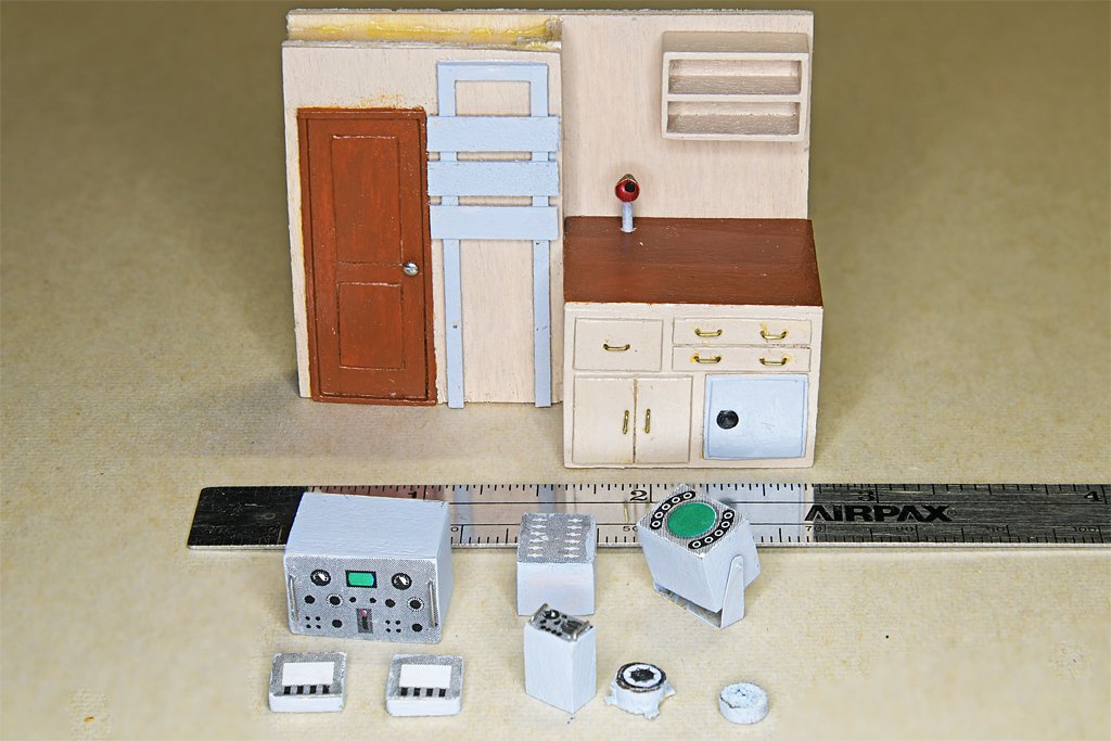 This is the pilot house aft bulkhead and some of the instruments that will be mounted there.
The large box is the Mk VII Magnetic Sweep Controller. Below it are two Navigation Light Panels. The small box is a KY-83S Keyer. Above it is a Transfer Panel for the Mk VII. At lower right are a gyro repeater and a barometer. Most of these parts mount on the gray rack to the right of the radio room door.
I found a photo of the Keyer and used it to create the graphic on the face of the box. The Mk VII controller graphic is fictional - I can't find a photo of it. The Transfer Panel graphic is also guesswork. The gyro repeater and barometer graphics are actual photos. The light panel layout is shown in the blueprints, but the graphic is guesswork.
The box that is mounted on a bracket is the ship's EDO Model 320A radar unit. It will be mounted on the pilot house forward bulkhead.
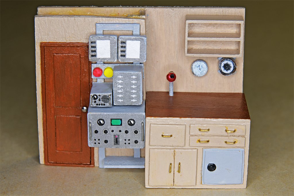
Here is the equipment mounted in place. The red object is the General Alarm switch, and the yellow one is the Chemical Alarm. The actual units were octagonal with a handle, but th 1:48 scale they are too small to model correctly.
The shelf below the Mk VII was for an electric megaphone.
I guess I should put some books in the bookshelf over the chart table.
-
I have been working on some of the fiddly bits in the pilot house.


These are the "megaphone" mouthpieces for the voice tubes. Four will be visible: one on the O2 level above the pilot house, one on the open bridge, one in the pilot house above the helm, and the fourth is on the chart desk in the pilot house. I took the dimension from the blueprint drawings, and printed the (very tiny) paper template from my CAD system. I made the pieces from 0.005 inch (0.13 mm) brass.


Here is a photo of the completed parts (left) on top of the chart desk on the aft bulkhead of the pilot house. One of these tubes came up under and stands above the chart desk surface where the navigator can talk to the bridge or O2 level station. The safe and drawers are shown in detail on one of the blueprint sheets, but I had to estimate the actual dimensions.
On the right is the chart desk positioned against the aft bulkhead. Just to the right of the door to the radio room is a frame for an equipment rack. Several pieces of equipment will be mounted there. All of this is like making dollhouse furniture.
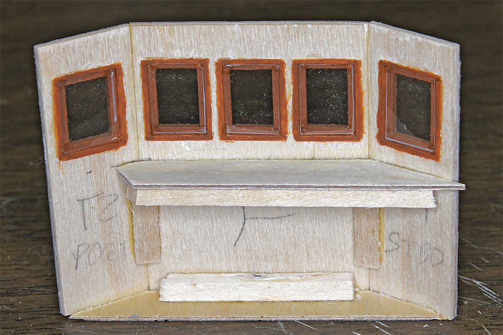
 This is the forward bulkhead for the pilot house. The shelf in front of the helm will support a magnetic compass, a gyro repeater, and propulsion control unit (throttle). There will be several instruments above the windows, and four tachometers for the engines will be mounted on the lower front on either side of the helm. The low shelf at the left will support the navigation radar control unit.
This helm is the Syren 1-1/4 inch (32 mm) kit that is 5 feet (1.5 meters) diameter at 1:48 scale. This is oversized - I learned from the blueprints that the original wheel was 4 feet diameter, or 1 inch (25 mm) at 1:48. The kit has 10 spokes and the original had only eight. If I can find an eight spoke 1" diameter wheel I will use it instead. Maybe I will scratch build one.
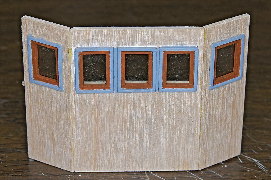
The "mahogany" window trim came out pretty good, especially after a coat of acrylic satin varnish.
The vertical parts were paneled in a light colored wood, hence the "straw" color (you might recognize from my schooner build). This definitely was not a stock Navy paint color. The panel above the windows, and the aft pilot house bulkhead and chart desk front are painted an off white buff color. Again, this isn't what the blueprint painting schedule called for. It says to paint the walls and overhead green. The Navy did use a pale "puke" green in interiors, but the photos I have show an off white color with no hint of green (maybe the colors faded in the slides before I scanned them). And overheads were always painted white.
-
Roel,
I have followed this build over the years, and it has turned out beautiful!
If the damage is on the port side, that means you were on the bridge's starboard, so you had the right of way! I guess the bridge just couldn't move fast enough to get out of the way.
-
-
Your eyes adapt to the darkness in less than 15 minutes, and it is surprising how much you can see in the "dark."
We could see unlighted fishing boats in almost any clear weather and calm seas. Heavy seas and rain made it more difficult. But even a small light could be seen from a great distance. Fishing boats often had a small light pointing down into the water to attract fish, and these were very easy to see at a great distance.
You can also see the glow of bow waves and wakes from light emitted by microscopic marine creatures.
I didn't have any trouble walking around on deck at night, and some of our decks were painted dark gray.
-
-
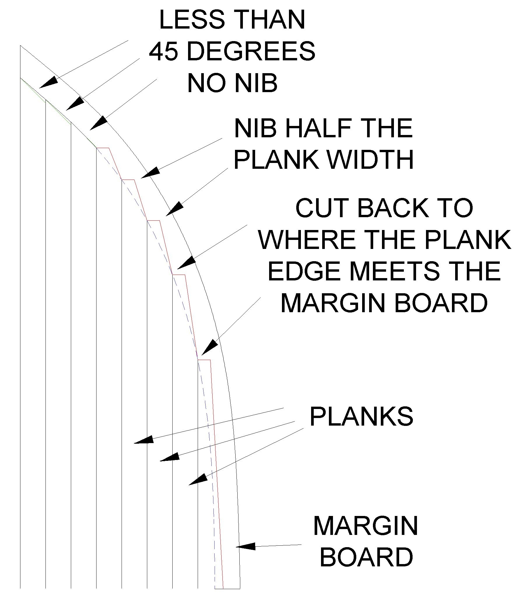
With your nibbing it looks like you are trying to cut each plank at the same angle. This is wrong, and you are about to discover the problem in a big way. The farther aft you go the deeper you are cutting into the waterway/nibbing strake/margin board. Eventually somewhere close to midships you will have to cut all the way through it.
 The purpose of nibbing is to avoid sharp pointed ends on the planks. These will tend to catch on ropes and other things dragged along the deck, and the plank tips will break off. And it is just easier to cut the nib than it is to try and match angles between the planks and margin boards exactly.
As a rule of thumb, never cut more than half way through the margin board. In some cases an even shallower cut is called for.
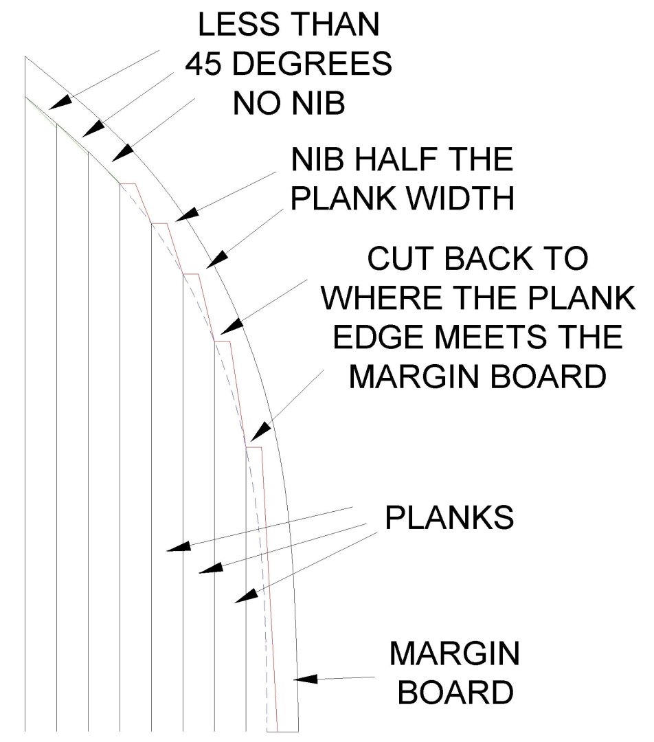
If the angle back along the margin board is less than 45 degrees (green lines - look closely) there is no nib and the plank is cut straight along the edge of the margin board. This is optional - it doesn't hurt to nib these planks too.
If the angle is greater than 45 degrees the plank is always nibbed into the margin board. The width of the squared off part at the end of the plank (red line) is about 1/2 the plank width (I have seen examples where it was 1/3 the plank width).
The angle of the nib at each plank is different. From the center of the plank the angle back is determined by where the edge of the full width plank meets the edge of the uncut margin board (dashed blue line). The nib cut (red line) runs from this point to the center of the plank at the squared-off end.
Near midships the edge of the margin board is almost parallel to the edge of the plank. Here you will need to be creative. Nib the plank as usual at the end. Then cut back to where the plank edge is half way into the margin board. Then cut straight back along the plank edge, never cutting more than half way through the margin board. At the other end of the deck do just the opposite for the outer plank, and nib the remaining planks normally.
- Coyote_6, Kenchington and SaltyScot
-
3
-
I have been working on the O1 level deck house and the pilot house details. First up is framing the windows.
I had already installed the window frames as mentioned above. Now I needed to install the windows themselves. Unfortunately, none of the real mahogany I have is small/thin enough, and I don't have the tools to make a lot of consistently small pieces. The sashes (the parts holding the glass) were 2 inches (51 mm) wide, and that scales to 0.42 inches (1.1 mm) at 1:48 scale. I just happen to have two packages of 0.0416 x 0.416 inch (1 mm x 1 mm) basswood scale lumber from Midwest Products Co.
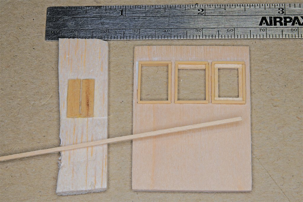
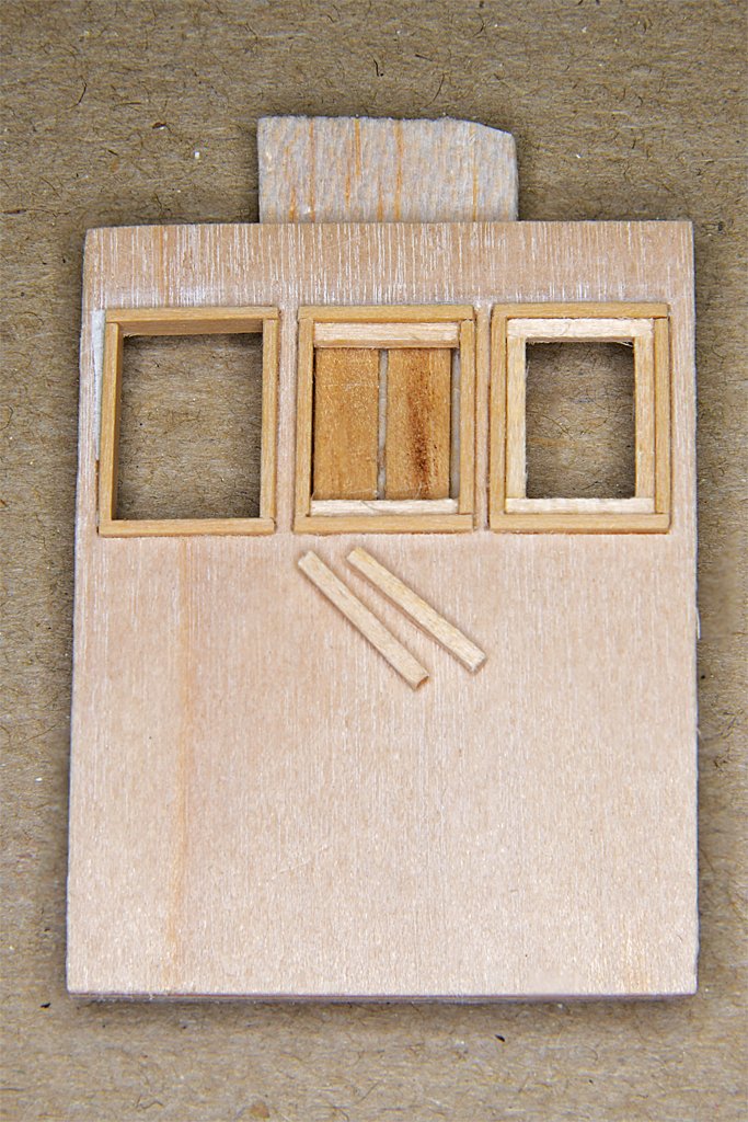 I needed to install strips of this wood into the window openings, more or less centered into the depth of the opening so there would be room for the "glass" behind the sashes. For this I made a tool from a piece of scrap wood (on the left in the picture) as a base and glued on two pieces of wood 1/32 inch (0.8 mm) thick that were shaped to fit into the window openings from the inside.
The window opening was placed over the tool. Pieces of the 0.042 x 0.042 inch basswood were cut to fit into the window opening and glued in place.
This put the sashes recessed a bit into the openings in the window frames, with space behind to install the clear window material. But what should I use for the "glass?"
I thought I would try to cut some glass microscope slide covers. In theory I could get four window panes from a single 22 x 22 mm 1 oz. cover glass. These varied in thickness between 0,0045 to 0.0065 inch (0.114 to 0.165 mm) and would be a perfect fit into the space behind the sashes.
HAH! Fat chance!!
After shattering a half dozen cover slips with nothing resembling a rectangular window pane I decided another solution was needed.
Note to self - never again even think of trying to cut microscope cover slips!
I do have some 0.005 inch (0.127 mm) thick clear styrene sheet from Evergreen Scale Models so I used that for the windows and air ports (seems I tried the cover slips for the air ports on the lower deck house sides and didn't learn the lesson then!).
I eventually finished all the window sashes for pilot house in the forward end of the O1 deck house. The smaller doors into the fan room at the rear were also installed. They were made the same way as the doors in the lower deck house. The air ports also were the same as in the lower deck house.
Next up was painting the window sashes and frames prior to installing the styrene window panes.
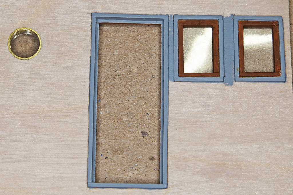
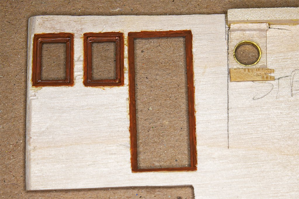
I mixed up a batch of reddish-brown "mahogany" paint for the sashes and internal window and door frames. The external frames were painted the same gray that the house sides will be painted. I wanted to finish painting everything close to the clear window panes so I don't have to worry about getting paint on them when the deckhouses are painted. The interior of the pilot house will be detailed with additional trim around the windows and doors, so I wasn't too anal about getting a clean edge around them now.
After the paint dried I glued the styrene window panes into the openings. The openings were all close to the same size (except one that was actually 1 inch narrower on the ship) but still varied by slight amounts. Each pane was individually cut to size and then glued into the opening with very small drops of Duco Cement in the corners of the openings.
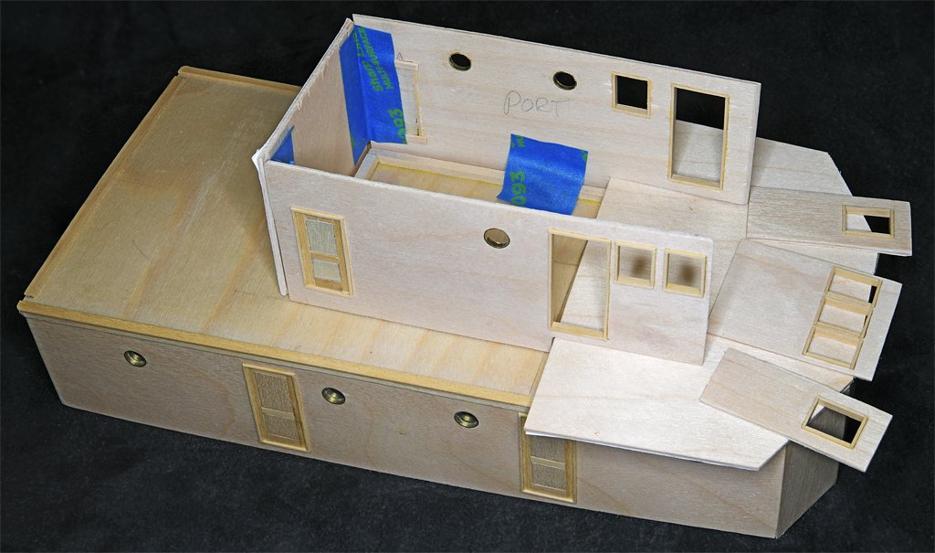
Then it was time to start assembling things. I had a lot of trouble with the forward end of the lower deck house and had to try three times to get everything aligned correctly. The O1 deckhouse was a bit easier. The house sides were parallel, and everything fit to the bridge deck at right angles.
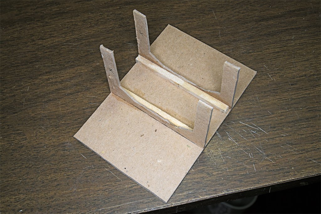
To help with the assembly I made a frame out of thick cardboard that would hold the pieces in place while the glue set. The two side panels for the front of the deckhouse fit to the center panel at 150 degree angles (30 degrees angled back from the front surface). The two vertical parts of the frame were carefully cut to the exact shape.
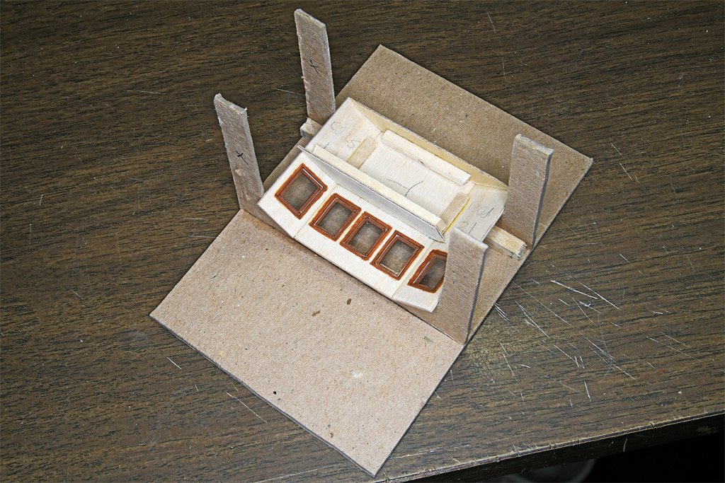
After gluing the three deckhouse front panels together along the edges additional pieces were glued on for reinforcement. A thin (1/32 inch plywood) bottom piece was used to support the angle of the front pieces, but this also serves to support the bottom panel of the interior of the front of the pilot house. Below the windows is the counter top of the interior where several instruments will be positioned in front of the helm.
 This is just the beginning of detailing the pilot house. Most of the interior was paneled, with mahogany trim around the windows and doors.
Nearly every surface was covered with instruments and wiring. The blueprints show the positions of everything in great detail. Making and wiring all of this stuff at 1:48 will be interesting.
The blueprints give the Navy part numbers for all of the equipment, but not much detail is included for what each part looked like. I am searching the Internet for photos, instruction manuals and such.
For example, at the lower left is the EDO Model 320A navigational radar receiver control. Apparently the Navy used these on several small vessels. But I can find only a few mentions of this device on the Internet and no photos. I have lists of US Navy electronic equipment from this period (1950s to 1960s) and none mention this equipment! Just tracking down the EDO company and it's products has been a challenge.
Add to this esoteric items like the Mk VII magnetic sweep controller and "navigational light control panels" and what I end up with will loosely represent all of the equipment here. But it will look like a pilot house, and that is the goal.
-
George,
Now there is a solution I hadn't thought of!
My question really was more general than the example I used. How do you widen a groove to fit another piece - or as you suggest - how do you shrink the other piece to fit the groove?
Some woods do become more pliable when wet than when dry. I have definitely noticed that wood is more "crushable" when soaked with water. So if you wet the wooden plank (bulkhead, whatever) you might be able to squeeze it into the groove. On the other hand, if you wet the sides of the groove you might be able to force a dry piece (wood, plastic, metal, etc.) into the groove. When everything dries the fit should be tight.
One catch is the type of glues you have used on the materials surrounding the groove. Some glues are water soluble, so soaking the sides of the groove could cause things to fall apart.
Another potential problem is that when the wood dries the plank or the surfaces around the groove might be "wrinkled" because of the displaced wood.
-
-
"The Masting and Rigging of English Ships of War 1625-1860" by James Lees (Naval Institute Press, Annapolis, Maryland, USA, 1990) has a lot of information about calculating rigging of square rigged ships. It is published in England by Conway Maritime Press, Limited, London.
"The Global Schooner" by Karl Heinz Marquardt (Naval Institute Press, Annapolis, Maryland, USA, 203) has much information for determining masting and rigging of schooners and other fore-and-aft craft. The ruled for schooner rigging are different from square rigged ship's rigging. Because the tophamper is much lighter than square rigging the masts are somewhat smaller diameter, and this has to be taken into consideration for calculating rope sizes. This book was also published by Conway Maritime Press.
-
I think it is time for another sea tale! This involves the mess decks on the Cape, so you can refer to the former post for a "map" of the main deck house where the mess decks were located.
Ptomaine!
Personnel on ships were grouped in Divisions with similar work and responsibilities. For example, I was the Engineering Officer and was in charge of the Engineering Division that maintained the engines and other equipment. The XO was the First Division Officer and they did most of the dirty work topside. A Division Officer's job (junior officer's job) was mostly involved with personnel matters, and sailors often created some interesting challenges.
I mentioned earlier that we had two of McNamara's 100,000 in the Cape's crew. They were draftees who failed the Navy's entrance exam. But the Navy was short handed so Defense Secretary Robert McNamara ordered 100,000 of them into the Navy to see if they were smart enough to chip paint. One of these fellows on the Cape was a few cans short of a six pack. I will call him "X" to protect the innocent. He was good at chipping paint and handling mooring lines, while under supervision. But he had some strange habits.
He was a momma's boy, and went home every weekend. Apparently his mother had put the fear of food poisoning into his brain, warning him to not trust anything but her cooking, or food she approved of. So when he came back to the ship he always carried a few cases of Coca Cola and canned corn beef hash. I was unaware of this until one of my men, a third class PO named Sylvester, told me about X. All he ate was canned corn beef hash, and all he drank was Coca Cola.
During meals on the mess deck X would wander through saying "Ptomaine, ptomaine!" I can still hear his squeaky voice crying "Ptomaine!" The crew took it in stride, recognizing that X wasn't all there.
One day while X was sitting in a booth in the mess decks drinking cola I enlisted Sylvester in a scheme to reprogram X. I asked him to join me in the booth next to X and just play along.
I told Sylvester about a strange case of vitamin deficiency, speaking loud enough that X could hear. There was a fellow in France who ate only egg whites and drank only white wine. Egg whites contain a substance that binds the vitamin biotin, deactivating it. And white wine contains no biotin. Normally there is enough biotin in a fingerprint to sustain a person for months or years. But after a while this guy flushed all of the biotin out of his system. Sylvester played along, asking questions.
The French guy had very peculiar symptoms that took doctors a long time to figure out. His was the first recorded case of biotin deficiency. So the moral of the story was that we need to have a varied diet so we don't come down with a strange illness no one has ever seen before.
A couple days later Sylvester came up and said "Mr. Hays, did you know that X was eating the ship's food?"
Sure enough, X started dining with the rest of us. I doubt if he told his mother! And he stopped saying "ptomaine" when walking through the mess decks.
Dealing with enlisted men's problems is a part of a Junior Officer's job. X was in the XO's First Division, and not my responsibility. But no one was telling the XO much about X's peculiar habits. Sylvester was one of my men, and perhaps X's best friend on the ship. So he talked to me.
And X did have other problems! Sylvester said X had athlete's foot on both legs all the way above his ankles, and the enlisted men who lived on board feared they would get it from the common shower. So I told the XO, and he told the Captain.
The Captain ordered X to report to the base hospital. Doctors were another of X's hang-ups. Apparently mom had told him only to report to her with medical issues - you couldn't trust doctors. I think she may have been a few cans short too. But X had been programmed in boot camp to follow orders, and the supreme order giver was the Captain. So X reported to the base hospital for treatment. Apparently the Captain outranked mom!
I have always found it humorous how the younger enlisted guys, aged 17 to 20 or so, looked up to junior officers as father figures. I was only 24!
-
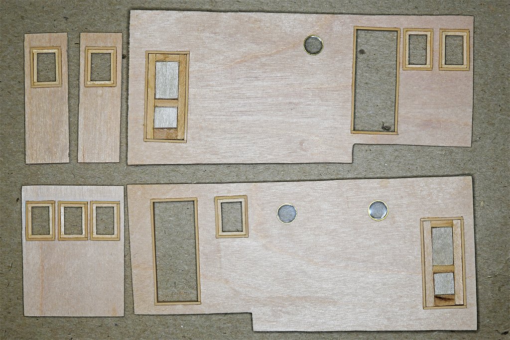
Now that the hull is (mostly) finished I can get back to work on the deckhouse. These are the O1 deckhouse sides.
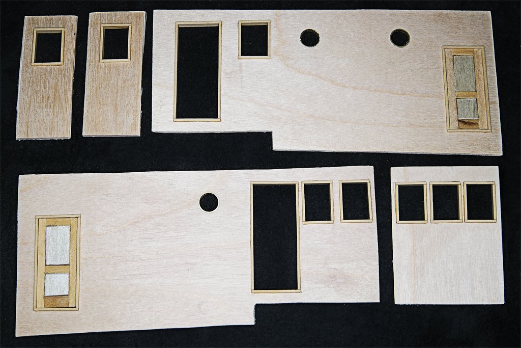
These are a lot more complex than the main deckhouse parts - mainly because of all the windows. I have installed the window and door frames. These are made of 1/32 x 3/32 (0.8 x 2.4 mm) basswood. (I meant to put a ruler in the photo but forgot). The window and door frames were made of mahogany, but on the Cape all of the exterior surfaces were painted gray. On our sister ship USS Cove MSI-1 the exterior parts of these frames were varnished. I debated whether to make the frames from mahogany and varnish them, but I decided to stay true to the real ship. The windows and interior frames were varnished mahogany and I will finish them that way.
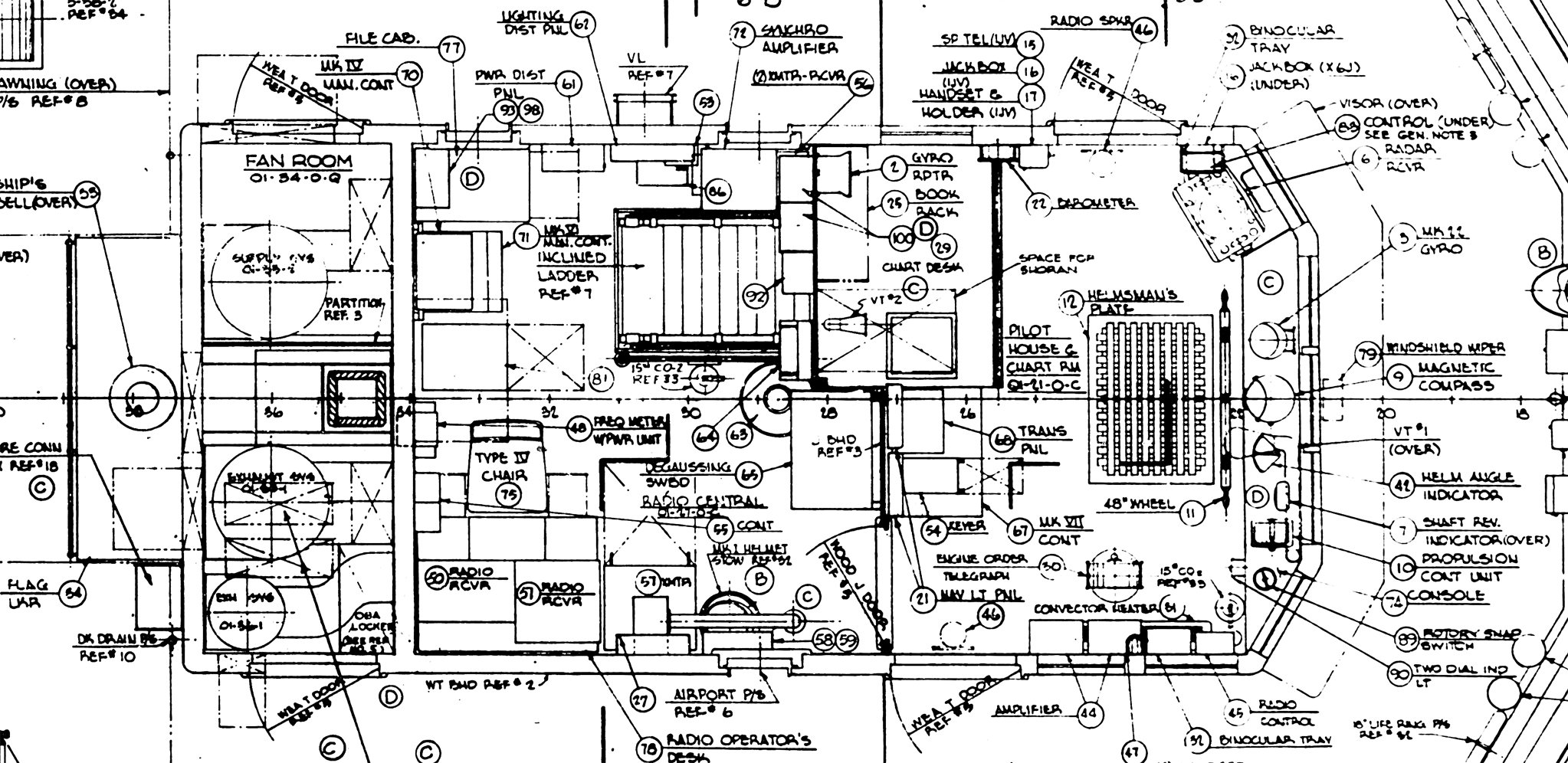
The windows will be an experiment. I will try to cut thin glass microscope slide cover slips to size and sandwich them between 1/64 inch (0.4 mm) wooden parts stained mahogany. Wish me luck on this! I could just put the window parts on the outside, but with the two pilot house doors open and seven windows much of the interior will be visible. I have detailed drawings of where all the equipment was located and one good photo of the pilot house interior, so I intend to fit it out with all those things. Here is a plan of the O1 level house and you can see where most of the equipment was placed in the pilot house.
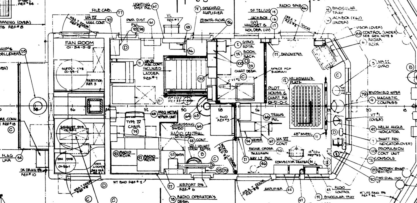
Behind (left) the pilot house was the radio room and a ladder down to the main deck level. You can get an idea how cramped things were from the size of the Type IV chair and the two foot (0.6 meter) wide door openings. The house was only 9 1/2 feet (2.9 meters) wide inside.
Here is a picture of most of the O1 level deckhouse parts in place on the main deckhouse.
The three pieces on the right with windows are the front of the pilot house. The center piece is cut to size, but the outer two narrower pieces with single windows are extra wide and will be fit in place after the other sides are glued together. Perhaps the trickiest part of making these was cutting the window openings from the 0.0625 inch (1.6 mm) plywood house sides. The spacing between those front three window openings is just 0.040 inch (1 mm), thinner than the plywood sheet. That required some very gentle filing to open up the holes without breaking something!
The main deckhouse was where the crew lived (the crews berthing was below decks in the fo'c'sle). Here is the plan for this area.

Up forward (right) were the officer's quarters. The CO's stateroom (C.O.S.R.) on the starboard side had a single bunk. On the port was the wardroom stateroom (W.R.S.R.) that the XO and I shared. It had two over/under berths one small closet and four drawers that we shared. The room was a little over 10 feet (3 meters) long with a sink up forward. The officers shared a small toilet and shower between the two rooms. Aft of the CO stateroom on the starboard side was the "wardroom" (officer's dining room). It had a small table with benches on two sides. Aft of that was the galley And aft of that were two restaurant style tables and benches that could seat maybe 16 crowded people. The crew was 18 enlisted men so the most senior petty officers (two 1st Class POs) dined in the wardroom with the officers. On the port side behind the officer's stateroom was the crew's head and shower and a ladder down to crew's berthing. The rest of the deckhouse held the engine uptakes, fire fighting equipment and the laundry. I have been on active fast attack nuclear submarines and I think they may have been more crowded that we were, but in either case there was a lot of "togetherness" in the crews. But at least we could go outside for fresh air. Of course, I will not be modelling any of these spaces.
- Paul Le Wol, Canute, Ras Ambrioso and 1 other
-
4
-
The blueprints mostly show the "as built" configuration. There were a few minor modification to the Cape over the years that are not shown in the blueprints. The searchlights were moved to the O2 level and the ships boat was stowed in a different position.
The Cleveland class blueprints show a series of modification while the ships were being built. For the Oklahoma City the problem was MUCH larger. That ship underwent major modifications to lower the center of gravity (make the ship more stable) after the original guided missile conversion in the late 1950s that are not shown in the blueprints. I suppose there must be drawings for these changes, but I guess that stayed at the shipyards where the modifications were made. I found no mention of these in the National Archives.
I have photos that I took while aboard both ships that show some changes.
- Canute, Ras Ambrioso, Coyote_6 and 2 others
-
5
-
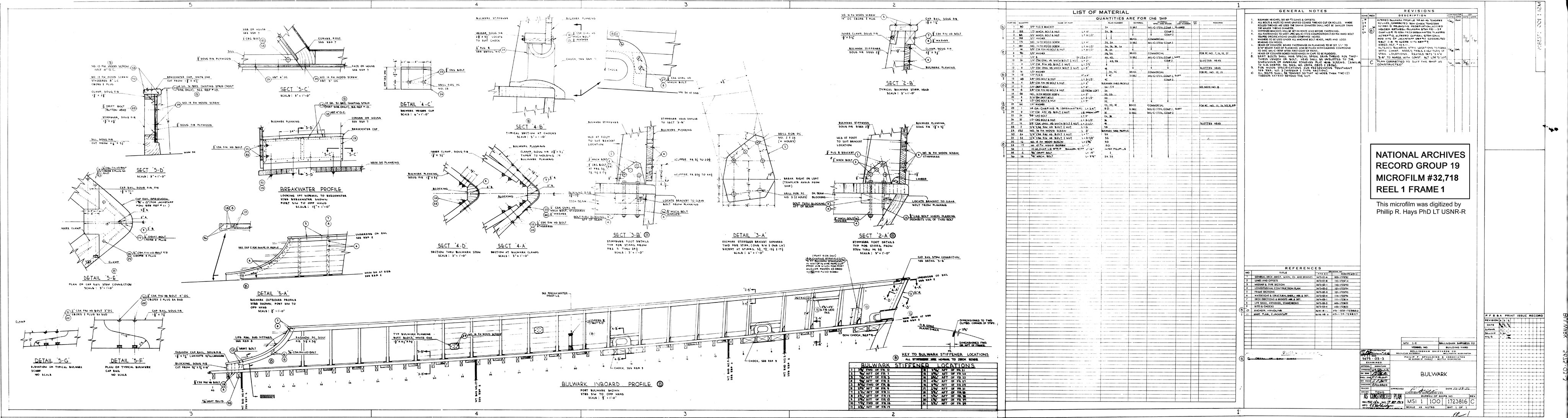
I am using the builder's plans approved by the US Navy Bureau of Ships (BUSHIPS) - microfilm blueprints from the US National Archives. For the MSIs there are 278 "frames" or BUSHIPS numbered drawings on the microfilm. However, some of these drawings have multiple sheets, up to two or three dozen pages. Everything from hull lines to lists of furniture, electrical and plumbing diagrams, door and hatch lists, etc. They even include the calculations for things like wind loading on the masts and the structural design to withstand the maximum expected winds. Very detailed. About 325 to 350 pages in all.
They tell almost everything about how the vessel was built - except, of course, the one small detail you really want to know! For example, they tell the dimensions and material of the planks for the outer sheathing, how to apply the sheathing to the hull (screws, adhesives and underlying waterproofing materials) and the width of the gaps between planks, but there are no clues to how the sheathing was arranged on the hull. I guess everyone already knew that when they were drawing up the plans.
The MSIs were small and only two were made, so the blueprint set is small. For the USS Oklahoma City CLG-5 modified Cleveland class cruiser I modeled (CAD) the index pages alone are a stack 6 inches high (25 to 30 drawings listed per page), with 8971 blueprints for the original Clevelands (27 were built, with many modifications) and another 3023 for the Talos guided missile modifications, plus more for the Terrier modifications. More than 13,000 pages of drawings, lists, calculations, etc.! But only 386 of those pages were useful for modelling the ship.
So if you want to build an accurate model of a modern ship you should work from the original blueprints. Unfortunately, some of the original sheets didn't make it into the microfilm sets, so there will still be a little guesswork.
Here is a typical example blueprint drawing showing how the forward bulwarks were to be constructed on the MSIs. Note the list of materials (screws, nuts, bolts, metal plates, etc.), quantity and sizes, plus the General Notes giving details about how the parts were to be assembled. A list of references to other blueprints is given. And of course many detailed drawings. This is a greatly reduced image only 1.6 mbytes and a bit blurry, but the original microfilm scan is 89.5 megabytes, and too large to post here.

-
After the tape is removed there are raised ridges of dry paint that formed along the tape edges. I have dealt with this in several ways.
1. I have VERY carefully scraped the raised paint with the tip of a #11 blade. The paint should not be too hard to avoid chipping. You need a steady hand for this!
2. On the Cape model I used a small file with a narrow tip. It must be held parallel to the hull surface, and it is best to align the shaft of the file along the paint edge. Using very gentle pressure the high points in the paint are filed off.
3. I have sanded the hull after the paint is very dry with very fine grit (#600) paper. Allow at least a week for acrylic paint to harden. Sanding the paint edges is incidental to producing a very smooth surface prior to applying a finishing coat of clear varnish or shellac. I would use this method to produce a glass smooth surface like on the hulls of modern racing yachts, or boats with fiberglass hulls.
****
I used a clear acrylic sealer (FolkArt all-purpose sealer49909) on all the wood on the hull. Even though the acrylic sealer is water based I didn't notice much raised "fuzz" after the first coat. The hull was sealed and sanded at least three times before the outer layer of sheathing was applied. That was sealed and sanded once (I didn't want to fill the cracks between the sealing planks). The deck was sealed and sanded at least twice. This produced a fairly smooth hull with visible planks like the original ship. It was all finished with #0000 steel wool before painting.
I applied water based FolkArt satin varnish to the deck and then finished it with #0000 steel wool. I plan to apply this varnish to the entire hull to get a uniform satin finish.
****
Many people avoid steel wool because it can leave tiny metal bits embedded in the paint. These can then rust over time in a humid environment. I always brush off the dust and loose steel wool fibers. Then I scrub with a stiff brush to remove any remaining metal, and wipe the surface several times with a damp rag. After this I rub a strong magnet over the entire surface - it is surprising how much metal "dust" remains. I have been doing this for half a century and have never had a problem with rusty fragments. This is in western Oregon where it rains from October to May. and people consider it a drought if the ground gets dry!
- vaddoc, Canute, Ras Ambrioso and 1 other
-
4
-
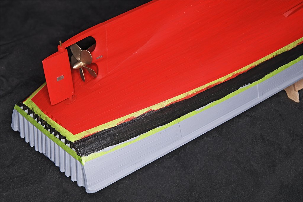
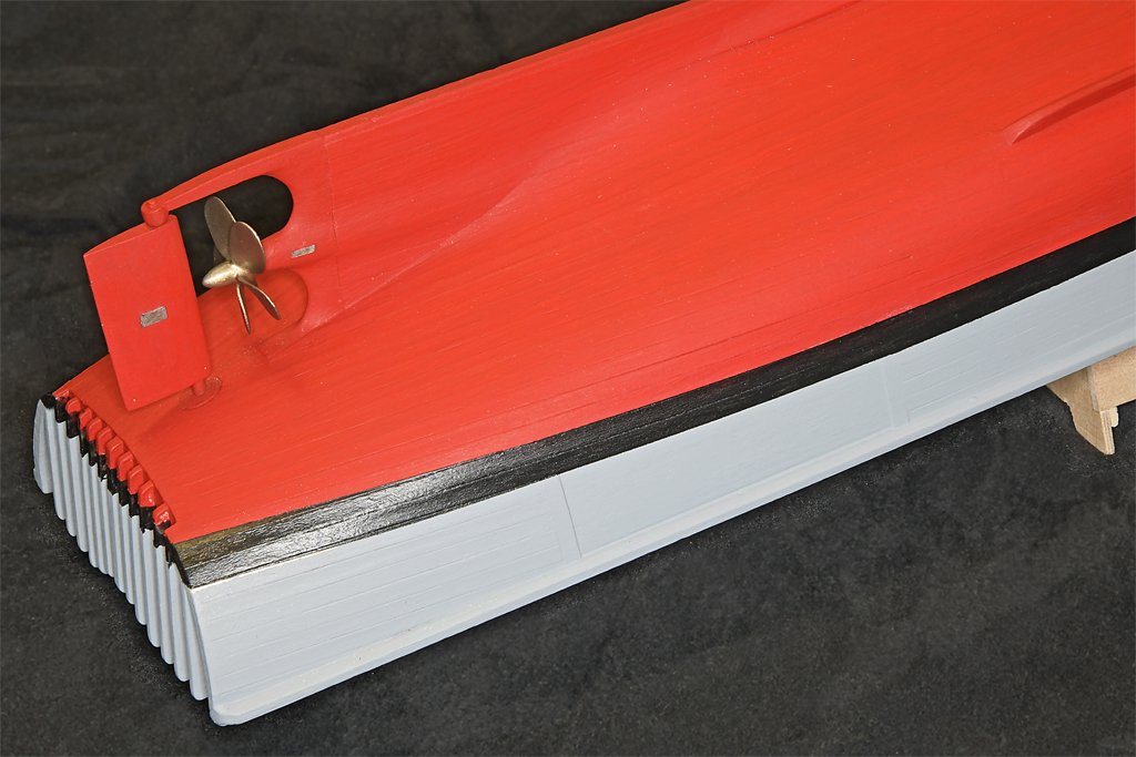
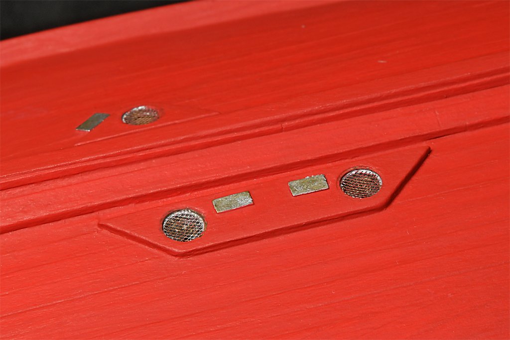
I have been putting the finishing touches on the hull.
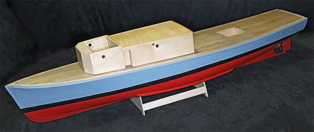
First off was painting the hull. I used the laser level to mark off the top and bottom of the boot topping (black stripe at the waterline). Then I used yellow-green auto detailing striping tape to mask off the boot topping area. The upper gray part and the lower red parts were then painted.
After the paint dried overnight I removed the striping tape. Then more tape was applied over the gray area just above the top of the boot topping. Another strip of tape was placed over the red paint at the bottom of the boot topping. This masked off the areas around the boot topping area.
Then I painted along the edges of the boot topping, using gray paint along the upper edge and red paint at the lower edge.
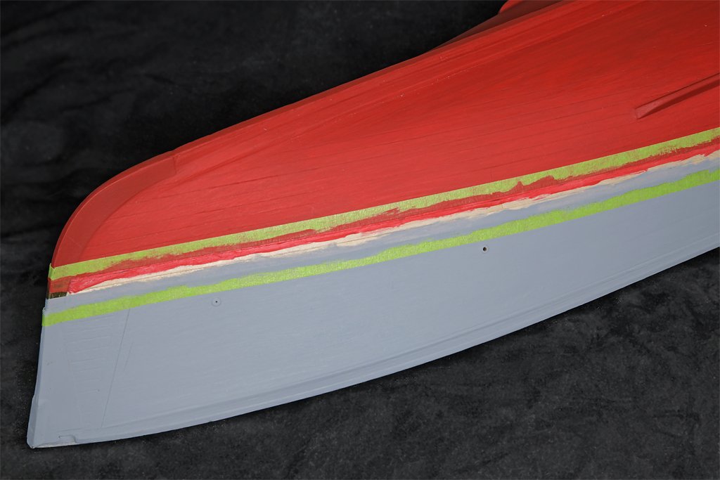
This paint sealed the edges of the tape. If any paint flowed under the tape it would be the same color as the paint already there.
After this paint dried I applied the black paint to the boot topping, flowing over the edges of the tape slightly. It looks pretty sloppy at this point.
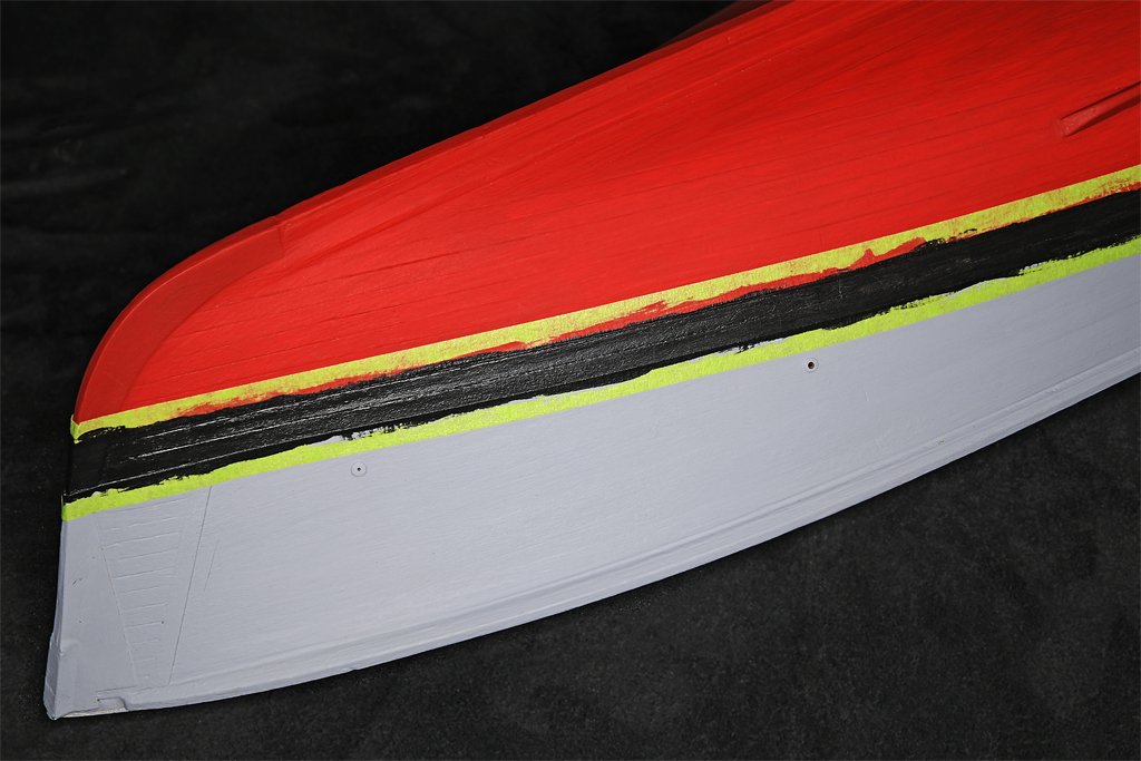
After the black paint dried I removed the striping tape. This left nice clean edges for the boot topping.
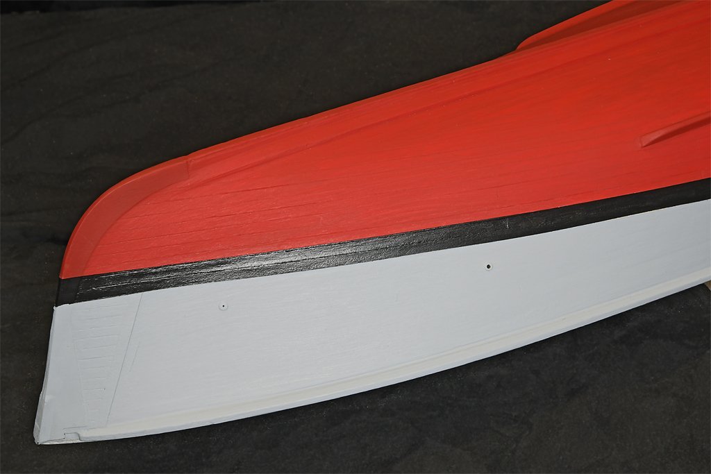
I still need to finish painting the transom. The areas between the guard timbers cannot be masked and must be painted by hand. I will wait until tomorrow morning to do this after a good night's sleep and my first cup of coffee.
The blueprints say the gray was Haze Gray formula 5H. I couldn't find any supplier of this color - it has since been discontinued for a different formula. The original haze gray used in WWII was a much darker blue gray. After the war the US Navy changed to a much lighter neutral gray that was called "Ocean Gray" for a while. I think this was what we used on the Cape and the USS Oklahoma City CLG-5. But the name seems to have been changed back to Haze Gray, Then later on yet another Haze Gray formula was created and I think this is what is used today. But there seems to be a lot of confusion as to which "Haze Gray" was used and when. I gave up trying to match the 5H color and used a fairly neutral light gray.
The red is supposed to be Anti-Fouling Red formula 121. Again I couldn't find this exact color, so I chose a moderately dark red. The blueprints call for Boot Topping Black formula 3. I just used some black paint I had in my paint box. The paints were all acrylic "craft" paints. They dry quickly and are water washable.
DecoArt Slate Gray DAO68
DecoArt Primary Red DA199
craft smart Black 371081
These paints coat well and required just two thin layers applied a day apart. The only problem I had came when I removed the striping tape after painting the boot topping. The tape lifted the red and gray paints from the brass stem band. The brass was smooth and shiny, and apparently did not have enough "tooth" (roughness) for the acrylic paints to adhere to. However, the paint had only dried over night, and if I had waited a week or two before applying the tape it might have held up better. But it was easy to touch up the missing paints.
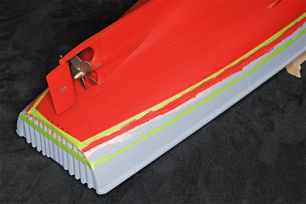
With the painting mostly done I could install the propeller and rudder. The Bluejacket Shipcrafters propeller was a bright shiny silvery color, but the blueprints call for a bronze piece. I painted it with FolkArt Brushed Bronze metallic acrylic paint. It dried hard, and I have seen no chipping of the paint with handling.
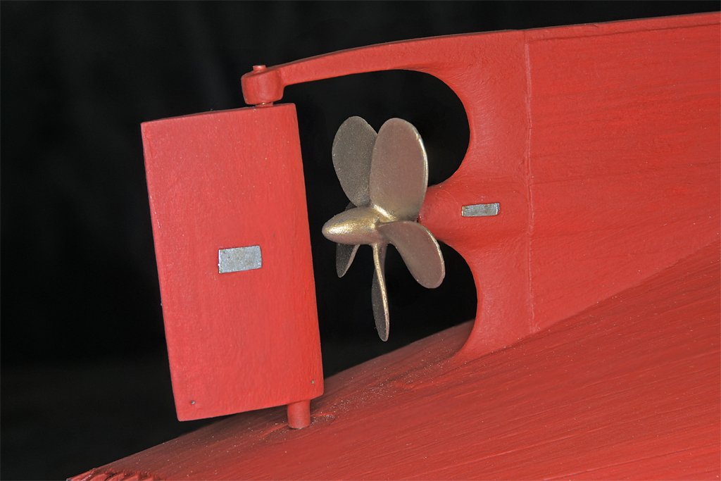
I left the sea chests for the propulsion engines and minesweep generator engines bare metal. The "zincs" around the sea chests, propeller and rudder are thin pieces of brass. I painted them with some ancient Chromatone silver enamel paint that I think I have had since 1977!
I still need to apply some rub-on numbers for the draft markings at the bow and stern. And there is the hull number to be applied in true Cape fashion. Then I will seal everything with a satin acrylic varnish.
-
This was one of my favorite ships, and you are doing an excellent job on the model!
- FriedClams, Paul Le Wol, Keith Black and 1 other
-
3
-
 1
1
-
No matter how you do it 3 mm blocks are fiddly! Your stropping looks good.
-
John,
Thanks. I did use a modified #11 blade as a scraper and it does work.
I used an example of a deck planking problem, but the more general problem is making any type of narrow groove. There have been several good suggestions so far.
-
Thanasis,
Good idea! The metal clip makes a good handle to control the sandpaper. The one problem I see with this is that the grit along the edge of the fold can remove material from the bottom of the groove, making it deeper. With the deck planking application it really won't matter much if the plank is a tight fit into the groove. I put glue on the bottom of the plank (you could put it in the groove) and press the planks into the groove most of the way. Then I use a wooden stick to press the plank down so the top of the plank is level with the tops of the neighboring planks. So the plank won't slide too deep in the groove.
Druxey,
You have hit upon the thing that worried me the most. There are several ways to widen the groove, and most have the potential to remove too much of one of the planks on the side that would make a very visible curve in the grout line.
However, one method to widen the groove hasn't been mentioned yet, and it is just asking for trouble! I did use a new #11 blade to remove wood from the sides of the groove! I held the blade flat against the edge of the planks on the side of the groove, and then rotated it slightly to get the sharp edge angled into the wood - like the blade of a plane. Then I carefully shaved very thin slices off the plank edge, moving in the direction with the grain so the blade wouldn't cut too deep. This was a "high pucker factor" operation. But it worked!
One of the problems I had with the thin planks was that they bent very easily, and if I didn't get the nibbing in deep enough into the nibbing plank the plank would develop a slight curvature. This happened a couple of times and I didn't notice until I had installed another plank or two. Looking along the length of the planks the curvature was obvious - the planks were supposed to be parallel to the centerline of the deck.
I had to rip up a few planks and then "plane" away excess material from the remaining planks to straighten the edges. Nasty! A few of the planks do have a slight taper toward the nibbed end, but because the entire batch of planks varied in width so much you would have to look very closely to see it.
-
Johnny,
I think Thanasis' suggestion to use sandpaper is a good one. If the paper was wrapped around something a bit narrower than the groove, so the sandpaper was a slip fit into the groove, it would remove material from both sides in equal amounts, keeping the sides more or less parallel lengthwise. That is a potential problem because I want the planks/grooves to have straight edges and more or less the same width through their entire length.
Making the grooves "\_/" shaped runs the risk of having different widths at the top edges (edges not straight), and that would be visibly noticeable in this application (deck planking).
For what it is worth, I did file the bottom edges of the paper "grout" to make the bottom of the plank a bit narrower. This helped get it started in the groove. But I didn't want to make it too tight because the paper is easily distorted if you force the plank into the groove, pushing the paper up and possibly out of the groove. If that happens you have to start all over again to replace the distorted "grout." So you really need a groove wide enough for the plank to easily slip fit in place.
I should also say that I really didn't have this problem when planking my topsail schooner deck because the planks were 5 mm (about 1/4 inch) wide. They did not bend easily. These 1/6 inch planks bend like wet spaghetti! And I was able to place straight runs of planking that were nibbed only at the outboard edges - no tapering to fit around a deck house with non-parallel sides. The MSI built posed some new challenges.


USS Cape (MSI-2) by Dr PR - 1:48 - Inshore Minesweeper
in - Build logs for subjects built 1901 - Present Day
Posted · Edited by Dr PR
One coffee cup coming up!
First I drilled out a piece of 1/16 (1.59 mm) brass tubing to about 0.050 inch (1.3 mm). Then I drilled two 0.016 inch (0.4 mm) holes for the handle. The handle is 0.012 inch (0.3 mm) brass wire. The wire was soldered into place and the interior filed to remove the wire stubs.
Then the cup was cut off from the tube, polished and painted. The paint needs to dry more before a second coat is applied.
Here is the 1:48 scale 3 inch (75 mm) cup next to the real 1:1 thing. I calculate it will take about 120,000 "cups" from the scale cup to fill the real thing.
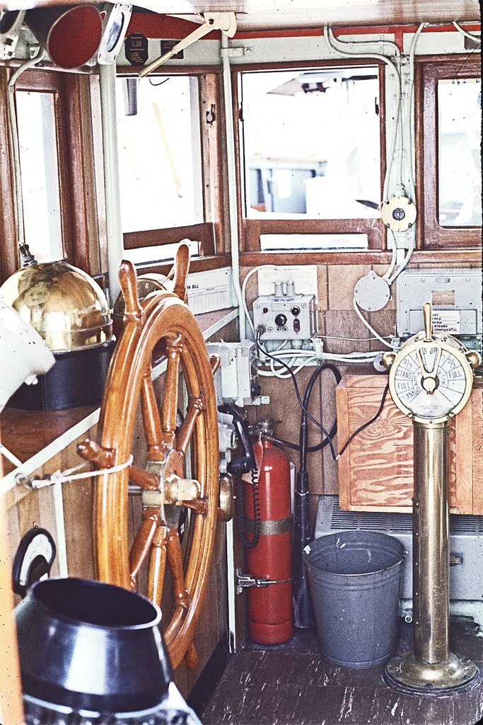
And here is the navigator's cup on the chart desk.
In the real Navy you would never place a coffee cup on the chart desk. But the Cape was McHale's Navy, and we went by Cape rules.
The really difficult part was painting the Navy seal on the cup. That took a steady hand!