


Dr PR
-
Posts
2,316 -
Joined
-
Last visited
Content Type
Profiles
Forums
Gallery
Events
Posts posted by Dr PR
-
-
Thanasis and Druxey,
Thanks for the suggestions.
I don't want to shape the plank - it is already shaped to the desired width, and has the paper grout glued to it. I am looking for ways to widen a narrow groove, preferably keeping the more or less vertical sides of the groove.
I suppose I could glue sandpaper to a thin enough stiff object so it could fit down into the groove.
-
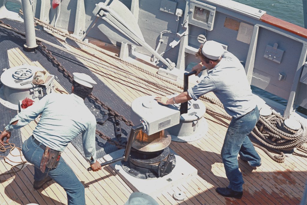
Could the steam in the photo in post #222 be a whistle instead of engine exhaust?
- Keith Black and Canute
-
 2
2
-
I have been planking the decks on my MSI model and ran into a challenging problem.

The planks are pretty thin (1/16 x 1/16 inch or 1.6 x 1.6 mm) and flexible. They are nibbed into a nibbing strake along the edges of the deck. The deckhouse sides are not parallel, so the planks have to be tapered to fit along the house sides. Planking at the bow and stern is pretty simple, but these deck sections meet along the house sides. Keeping the decking pattern straight and parallel to the centerline was pretty tricky in this area!
 The planks have 0.005 inch (0.13 mm) black paper "grout" glued along the edges.
The last plank between the forward and aft planking is nibbed into the nibbing strake and sandwiched between two neighboring planks. Because it is the last plank it has paper grout along both edges.
It is a very tight fit into the groove between the neighboring planks. And because the planks actually varied quite a bit in width it was a problem getting the last plank to fit into the groove.
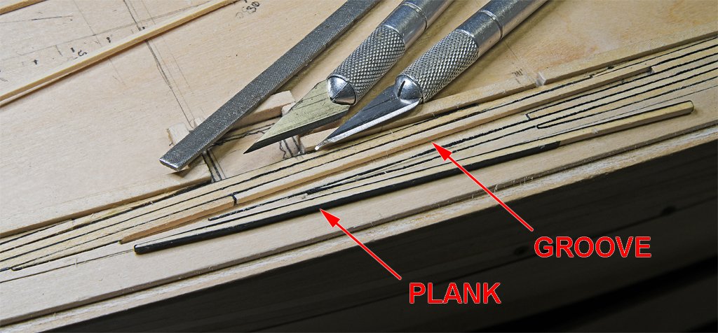
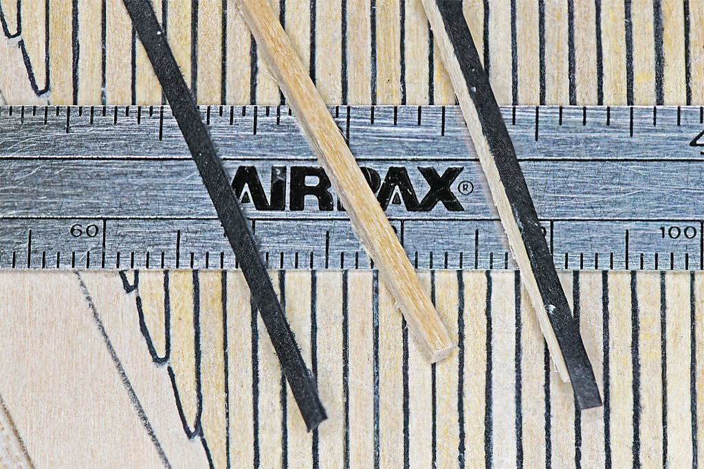
Here are a couple more photos to illustrate the problem.

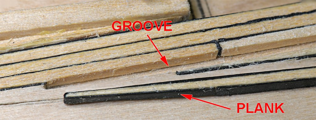
QUESTION: How would you go about widening the groove so the last plank would fit? This is a pretty narrow groove!
The small file shown in the pictures was 0.055 inch (1.4 mm) thick, only slightly thinner than a plank. It didn't remove much material and I had to be careful not to foul the opposing top edge of the neighboring plank. And it tended to remove more material from the bottom of the groove (not good) than along the sides.
What other method would you suggest to remove very small amounts of wood from the sides of the planks along the groove?
-
I'm back! I was occupied for about 2 1/2 weeks auditing the books for a non-profit that I am Treasurer for. I was checking every penny coming into and leaving the organization for 13 years, including restricted and unrestricted funds. I found a few errors, and after corrections everything balances for every month of the entire 13 years!
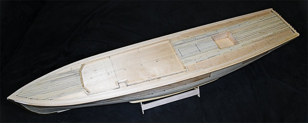
Then I finished laying all of the deck planking on the Cape model.
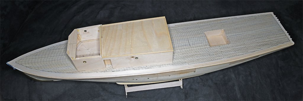
Don't ask how many individual planks there are - I have no idea! But there are a lot!
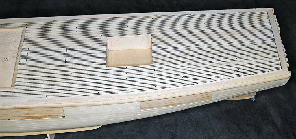
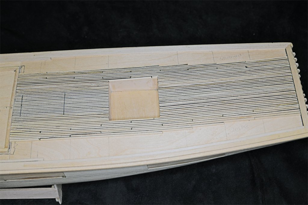
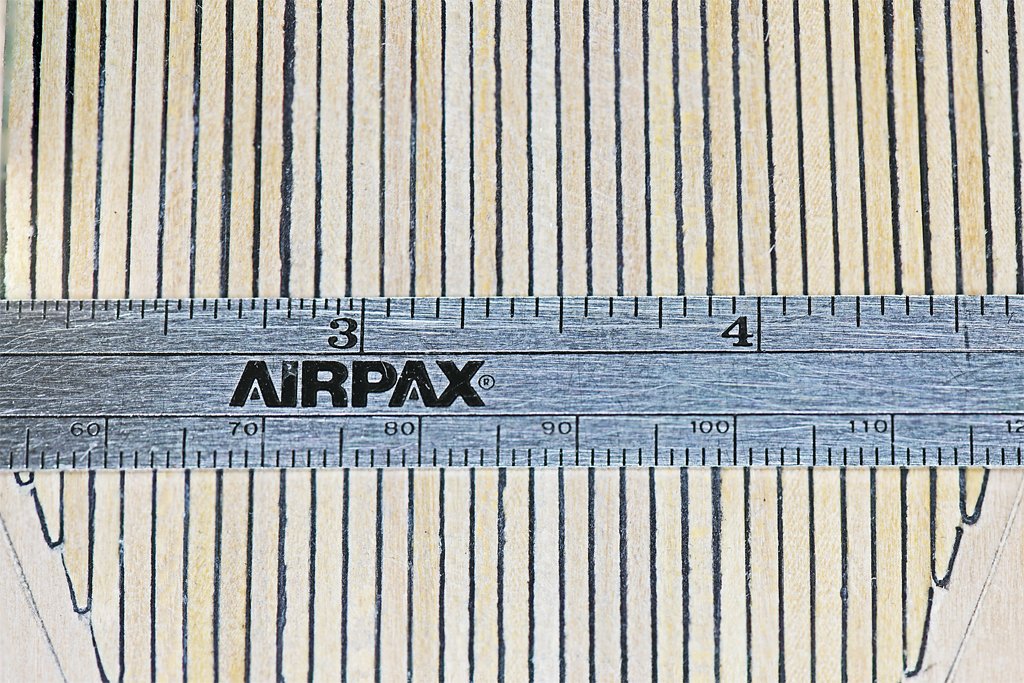
Just aft of the superstructure are two grouts running perpendicular to the plank lengths. This was a "portable" or lift out deck section directly above the main propulsion engines. This is still a rough planking. I have scraped, filed and sanded a bit, but the final smoothing and finishing is still to do.
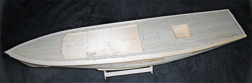
The planks varied in width and height between 0.052 and 0.072 inch (1.3 and 1.8 mm). I carefully measured distances from centerline to deck edges all along the length of the ship - and they were the same everywhere (I was pretty careful with this when I put the plankshears and nibbing strakes on). I figured random choices for planks would even out to port and starboard, but it didn't work that way (Murphy again). The starboard side at the stern gained about 1/4 a plank width at the edge of the deck well. From there I used thinner planks on the starboard side and thicker planks to port. The port side came out perfect with a full plank width finishing out the planking along the stern planksheer. But the starboard side was still almost a half plank too wide and had to be cut into the nibbing strake. But I doubt anyone would notice, and that area will be covered with minesweeping gear anyway.
The next time I plank a deck - especially if the planks are so thin that they bend easily - I will draw a series of lines parallel to the centerline and equally spaced on either side. These will serve as references to catch any planking "creep" wider or thinner on one side from the other.
The deck planks are about 1/16 x 1/16 inch (1.6 x 1/6 mm) and that is pretty small to be making nibbing. Because the deckhouse sides are not parallel, and the nibbing strake curves along the deck edge, the planking pattern was pretty complex along the sides of the deckhouse. This led to a problem with tapering planks along the deckhouse sides and nibbing planks into the nibbing strake. Bringing the decking from the bow and that from the stern together caused a problem, and this was exacerbated by the varying plank widths. The starboard side came out almost perfect, but I had to do some creative planking on the port side to make things come out right.
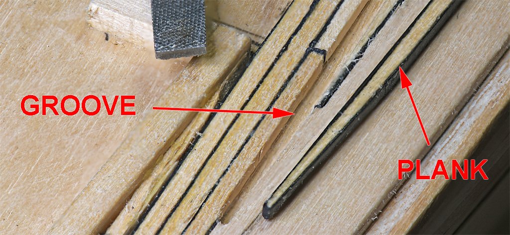
The last plank on the model ended up sandwiched between outboard nibbed planks and inboard tapered planks. It had to fit into a one plank wide groove - and was nibbed into the nibbing strake. And because it was the last plank it had paper grout strips down both sides. I picked a pretty narrow strip (about 0.060 inch or 1.5 mm) but it was a tight fit with the paper grout glued on. This called for some creative widening of the groove between neighboring planks. But it finally dropped into place with a bit of pressure.
I know some people think the grout between planks on a model should be more imagined than seen. But the Cape's decks were holystoned and bleached, and the grout stood out very visible.
The "grout" on the model is black paper 0.005 inch (0.13 mm) thick, and that is 0.24 inch at 1:48 scale. The blueprints say the grout was 1/4 inch wide in the ship's decks.
-
I would search the US Patent Office for vertical non-condensing steam engines. I would expect to find quite a few - with drawings. Just pick one dated from about the time the tug was built.
- Glen McGuire, Keith Black, John Ruy and 2 others
-
4
-
 1
1
-
By all means do start a build log! No build is perfect, and our explanations of how to do things aren't always clear. Another log will just provide more information for others to follow.
-
Your last photo shows the outer edge planks with "hooks" that the next plank fits into. But the drawing above it shows only one plank "hooked" where a separate "nibbing strake" fits into. The subsequent planks are nibbed into this nibbing strake. In some plans the nibbing strake is called a "margin plank."
- Paul Le Wol, FriedClams and Keith Black
-
2
-
1
-
Interesting. Hogging in pointy boat hulls results from less water displacement at the bow and stern, and therefore less lift to support those parts of the hull. Midships is broader and displaces proportionally more so it has greater lift. So the bow and stern droop, causing the hogging.
But in your sternwheeler the hull is rectangular. If it was a 3D rectangular solid it would have the same lift at all parts of the hull and would not be subject to hogging. I suppose it might have been tapered wedge-shaped below the waterline at the bow and stern, like typical flat bottom fishing boats. This would lessen the displacement, and therefore lift, at these parts. That would result in hogging.
The placement of heavy machinery and deck houses would also influence displacement. For example, the weight of the paddlewheel hanging aft of the hull would pull the stern down. The deckhouse up forward would push the bow down.
I doubt that a lot of nautical engineering went into the construction of this boat so it could have been very prone to hogging. The pipes you show could have been an add-on after a few years of operation when the hogging became apparent.
- Glen McGuire, Keith Black, Canute and 1 other
-
3
-
1
-
I nibbed the deck planks on my topsail schooner build, and I am currently nibbing the planks on my minesweeper build:
The schooner planking wasn't too bad because the planks were 5 mm wide. The minesweeper planks are 1/16 inch (1.6 mm) and it is much harder getting neat nibs!
I hope someday to resume my 1:96 scale USS Oklahoma City CLG-5 model, and I was planning on planking the deck with nibs. But those planks will be about 1 mm (0.040 inch) wide and there is NO WAY I can nib those tiny planks neatly!
-
The studding sail booms were wood, the boom irons were iron. The position of the irons and booms depended upon if the ship was continental (Europe), British, or commercial (non-warship).
The irons were attached to the yard arms in several ways, again depending upon who operated the ship.
- Keith Black and Glen McGuire
-
2
-
Some lines will not have large coils at the belaying point, especially if that they haul on is let all the way out. For example, if a foresail is reefed the halliard will be let out all the way with little left to coil.
On the other hand, if the sail is hauled all the way up there will be a lot of extra halliard line to coil at the belaying point.
As you say, the stays on the jib boom and flying jib boom do not have to be adjusted much, so there never will be a large coil of line at the belaying point.
- Coyote_6, Chuck Seiler, Glen McGuire and 1 other
-
3
-
1
-
serpe,
What do you want to achieve with your model?
-
Most of the wood we use for modelling has been dried - unless you cut strips from fresh wood. Wood shrinks significantly as is dries, and swells when it gets wet. Even just high humidity can cause wood to swell a bit. This swelling and shrinking can cause cracks to appear in seams between planks months or years after the model was built. I coat the interior of the planked hull with thin epoxy to glue everything together solidly. This prevents cracks from appearing due to changes in humidity.
When you soak planks for bending, be sure they are dry before putting them on the model. If you bend planks on the model, as I do, use only a small amount of water brushed on the strip, and heat until the moisture evaporates.
-
I followed Tom Lauria's YouTube procedure in Making Sails for Ship Models From Silkspan. Here is a link:
Using your frame should give better results!
- Keith Black, FriedClams and Lecrenb
-
3
-
I use a small paintbrush to loosen the dust. I hold the end of a vacuum cleaner hose close to the model to suck up the loosened dust.
CAUTION: Remove any loose parts (not fastened down) first or you may have to sort through all the dust and lint in the vacuum bag. Guess how I know?
- CPDDET, davyboy and Knocklouder
-
1
-
 2
2
-
Most people seem to use a plank bending method with the planks off the hull and in some type of jig. Some boil or steam the planks, and some people just soak them. In my opinion this is all way too much trouble and the results are less than perfect.
For me the best way is to shape the plank on the hull, where the hull serves as the jig and has the exact curvature and twist necessary. Here are a couple of links that illustrate this method.
You don't say what type of "plank bender" tool you are trying to use. That could influence the method you try.
-
When I first saw your pictures I imagined an auger screw stoker mechanism as used on some steam locomotives. But then I realized it was a conveyer bucket system. These were in common use so it makes sense.
But it would be interesting to see how it actually worked. It was probably steam powered. When steam pressure was high the stoker would run slower, and when the pressure was low it would have to "shovel" faster. I hope you find more information about how it worked. I wonder if it was patented?
- Canute, Keith Black and Glen McGuire
-
3
-
Sagrado,
Since the HMS Beagle was a British Royal Navy ship you should look for information about how the Royal Navy was rigging the lifting tackle in the first half of the 1800s.
I would bet on the rig shown in your first images from "The Age of Sail."
However, keep in mind that there were probably as many ways to rig these tackles are there were ships, Captains and Bosuns. If you cannot discover exactly how it was done on the Beagle (and did the method change over time?) you are free to do whatever you want so long as it is reasonable.
-
I have been planking the main deck.
As you look at these photos keep in mind that this is the rough deck. It has not been sanded or sealed.
The blueprints say plank ends will be spaced at least four frame spaces with three passing strakes between butts in line. The planks should be laid parallel to the centerline "... in as long lengths as practicable ..." How long was "practicable" when they were building this ship?
The planking strips are 24 inches (610 mm) long. I decided to use 5 inch (127 mm) long planks (20 scale feet or 6 scale meters) because that is 16 frame spacings. This way I can use multiples of 4 frame spaces (1.25 inch or 31.75 mm), or planks 1/4, 1/2, 3/4 and 1 plank length long to stagger the plank ends lengthwise. Some of the planks are actually longer that 16 frame spaces at the bow and stern.
 The blueprints specify deck planks 2 5/8 inch (66.7 mm) square, or 0.055 inch (1.4 mm) at 1:48 scale. The closest commercially available strips were nominally 1/16 x 1/16 inch (0.0625 x 0.0625 inch or 1.6 x 1.6 mm). However they range from 0.055 to 0.075 inch (1.4 to 1.9 mm) and none are actually square in cross section.
I cut the strips to the desired plank length and then glue a strip of black paper to one side. I usually place the narrowest dimension of the plank vertically so it will take fewer strips to plank the deck.
The paper is about 0.005 inch (0.127 mm) thick, and this is 0.24 inch (6.1 mm) at 1:48 scale. The blueprints call for a 0.25 inch (6.4 mm) grout so the paper and glue are just about the perfect thickness.
The paper strips were cut on an ordinary paper cutter, eyeballing the widths, so they are not uniform. They protrude a bit above the tops of the planks. With handling the tops of the paper strips "fuzz out" and appear wider than the nominal width, making the grout look non-uniform. But after all the planking is done the deck will be scraped, sanded and finished with #0000 steel wool and the grout lines will be much more uniform in width.
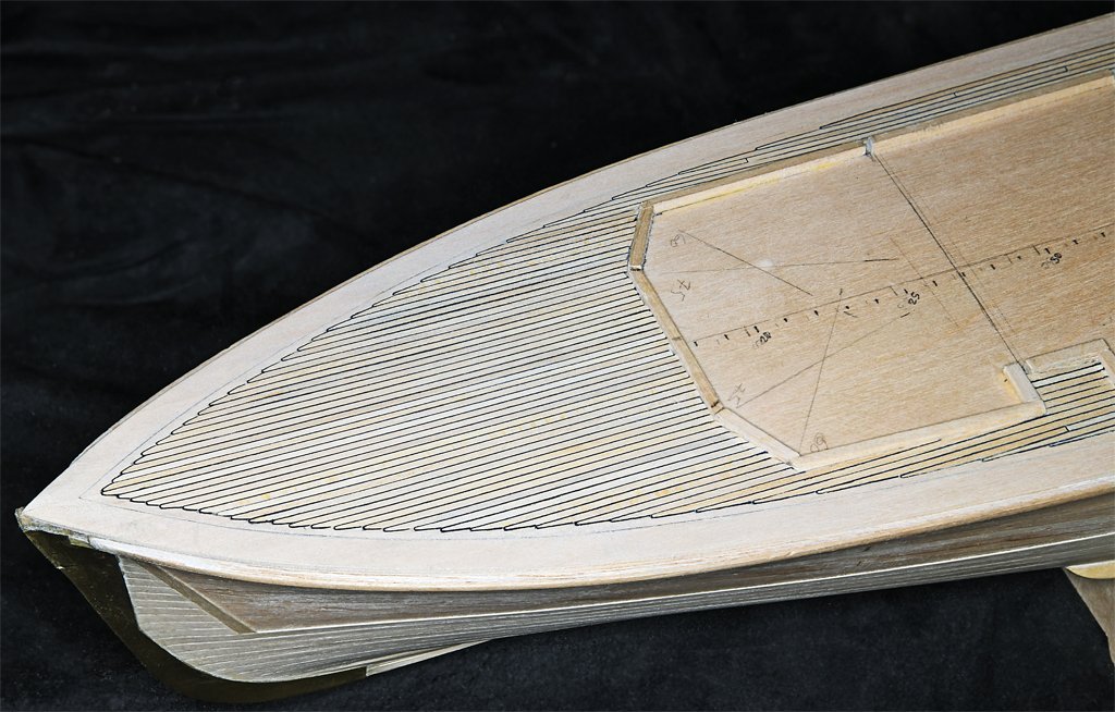
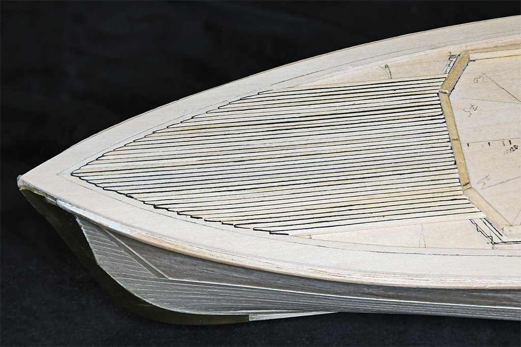
Nibbing the planks into the nibbing strake along the edge of the deck is much harder that it was on the topsail schooner build - it had 5 mm wide planks. As you can see in this macro photo the nibbing isn't "perfect." It has taken a bit of practice to get it more uniform in appearance, and I screwed up in a few places.
Fortunately part of the fore deck is covered by a steel chafing plate where the anchor chain runs, and this will cover the worst of the screw-ups! Phil 1, Murphy 0!
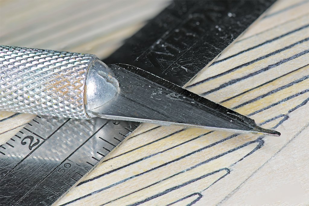 I soon learned that I could not cut uniform nibs with just a #11 hobby knife blade. The solution was to use an old, dull #11 blade with a broken tip, and shape the tip to make a "nibbing tool."
I used a grinding wheel in my motor tool and cut the tip to about 0.030 inch (0.76 mm) wide, with a chisel tip on the end. This is about half a plank width, and that is how wide the nib tip should be. I ground a cutting edge on the end, and then sharpened it on a whet stone.
I first use this tool to make the initial cut at the edge of the nibbing strake. Then I cut back from there to where the plank edge meets the edge of the nibbing strip. The plank is then shaped to fit the nib cutout. I usually have to trim the plank a bit narrower at the nib to account for the thickness of the paper grout.
No two nibs have the same angle cut, and the nibs get longer as the planking progresses toward midships. Some of the planks will have very long tapers, especially along the deck house sides. It is pretty tricky trying to cut long straight tapers into the nibbing strake.
-
Valeriy,
I am aware that the calculations for creating truncated cones are on line - I even have them in an ancient printed analytic geometry text book. But the Internet takes the fun of doing the trigonometry out of it, doesn't it?
But where your experience comes into the story is that you know how to do it, and know what to look for to do the calculations. And of course you do excellent work with brass and soldering! That is part of your talent.
-
Valeriy is too modest - he is obviously one of the most talented ship modelers on the planet! All of the great tools will not build a model, not even in the hands of an untalented modeler.
The geometry of the "ventilator visors" is not trivial. It looks like he made them from four pieces - two curved ends and two straight sides. Those curved ends are halves of a conic section, and anyone who has tried to figure out the correct "flat" layout for a conic section knows it isn't trivial. Try cutting a truncated cone with specific angles from a piece of paper and you will see it isn't easy!
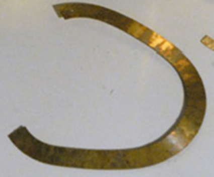
I designed this single piece "visor" in 3D CAD and that takes a lot of patience. In this case the smoke pipe had different radii fore and aft.
I had to flatten the 3D model into a 2D plane, one facet at a time (the program didn't have a "flatten" function). That was very tedious!
Then I photo etched the part (sorry for the blurry picture).
It was a lengthy and non-trivial process that took several days.
Valeriy is very good at this sort of thing and makes it look all too easy!
-
It was common on many vessels (especially smaller non-military ships with small crews) to forego the becket and just tie the standing part around the block strop.
In some cases the standing part of the tackle was tied in a knot around the block strop, as illustrated in Monfeld's Historic Ship Models on page 245.
Some people just loop the standing end under the block strop then pull the end back and seize an eye around the strop. This is perhaps the best way to attach the standing end on small scale models.
Sometimes a separate length of line was pulled under the strop, looped around a thimble and seized to create a becket.
And on some ships a separate becket was seized into the block strop. I suspect this method was more common on naval ships with large crews with little to do when not engaged in battles.
Unless you know the exact way blocks were stropped on the original vessel you are modelling you are free to use whatever method appeals to you.
- palmerit, Keith Black and robert952
-
3
-
Gary,
Not as nice as it might have been! A lot of things were screwed up pretty badly when the glue set. The angles of the front three panels were way off. I tried to repair the problems, but the "repaired" piece still had a lot of problems.
If at first you don't succeed, try, try again.
The problem seems to have been caused by the side pieces moving back and forth while I was assembling all of the panels and supports for the front of the superstructure. The thing just wasn't rigid enough to hold its shape.
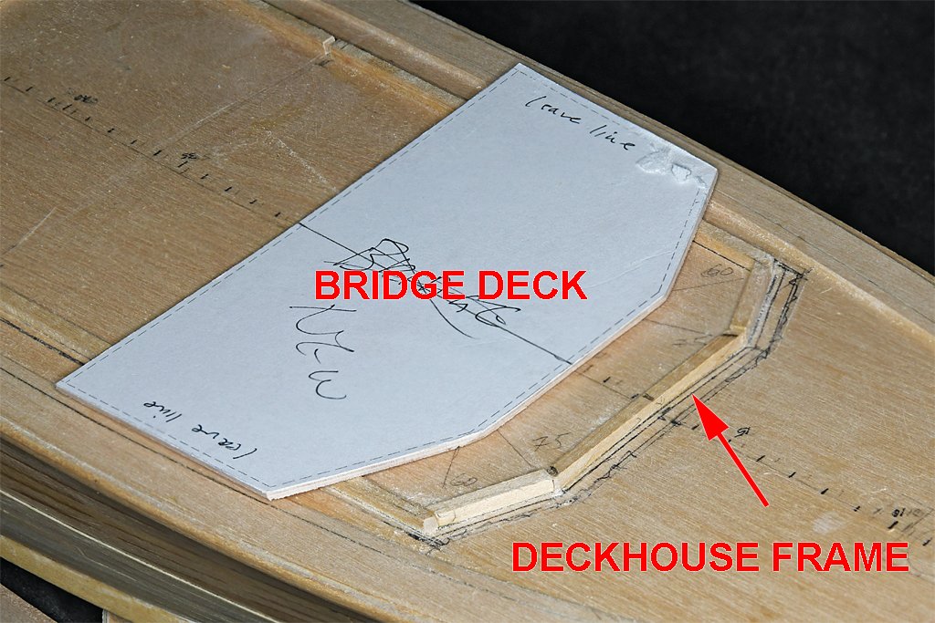
The blueprints show the front panels resting at an 85 degree angle to the deck, and they join each other at 150 degree angles. At the sides they join the deck house sides at approximately a 120 degree angle, but not quite because the house sides are not parallel.
I double checked the deckhouse frame that is glued to the sub deck against a printed template, and all of the angles were correct. Likewise the bridge deck - that rests on the deckhouse sides - also had the correct angles.
But the front panels did not align properly at the top edges with the bridge deck - they were way off in places! There wasn't any way to correct the errors, so the three front panels were chopped out and I started over.
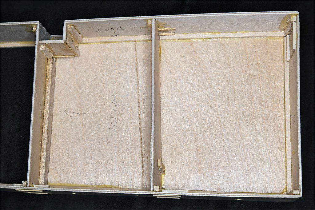 The first thing to do was realign the sides and rear bulkhead to the deckhouse frame and glue it all together.
Then the top rear O1 level deck was glued on. Once this was in place the structure was rigid. This piece is 1/16 inch (1.6 mm) plywood and was pretty stiff. The deck has camber, but no sheer. The interior bulkheads were all cut with the camber, so I needed to bend the plywood to the correct curvature.
I wet the plywood and then bent it over a couple of wooden sticks. The edges were clamped to a very stiff 1/4 inch (6.35 mm) thick piece of aluminum plate. Then the plywood was pre-heated with a hair dryer and the whole thing was placed out into the noon day sun. After a few hours at 80+ Fahrenheit (28 Celsius) the plywood was dry and had adopted a nice camber.
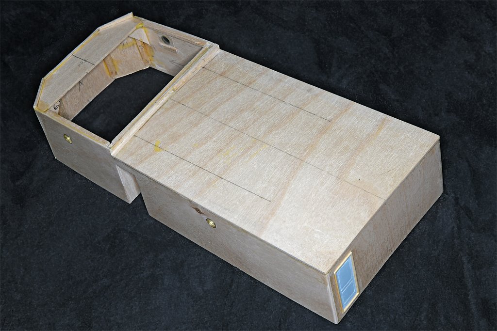
While the glue was setting I added the walls for the small nook in the port side of the deckhouse. There is a scuttle in the main deck here that was the escape route for the forward minesweeping generator engine room.
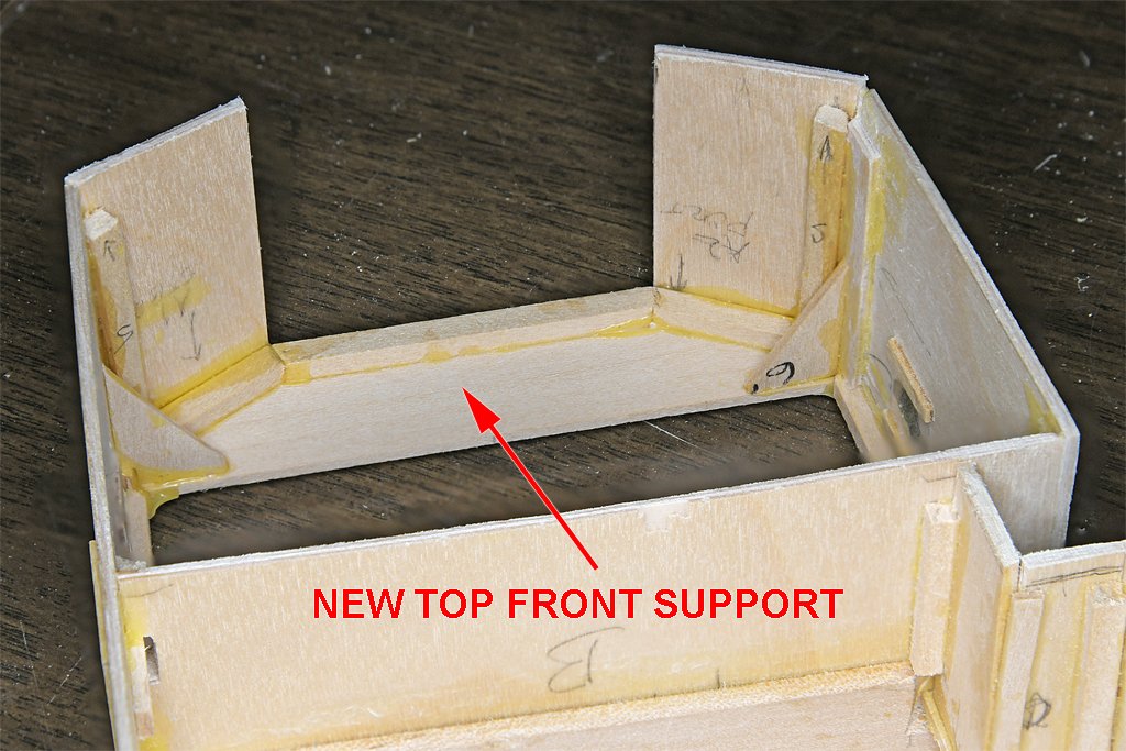
 With the rigid deckhouse structure to work with I devised a simple solution for aligning the front panels. I cut a piece of 1/16 inch (1.6 mm) basswood to match the shape of the front of the deckhouse frame and bridge deck.
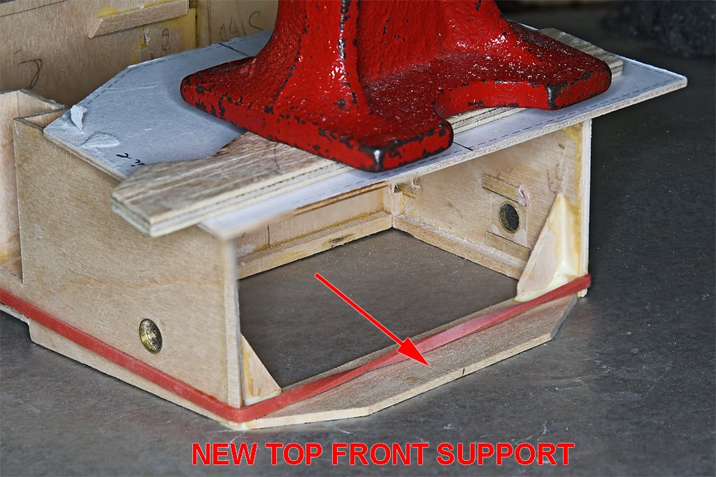
After the leading edges of the sides were prepared at the proper angles to mate with the front pieces, the new top front support was glued into place, with a couple of additional supports to strengthen the assembly.
In this photo the deckhouse is upside down and resting on a sheet of waxed paper. I applied an excess of Titebond Original glue to be sure everything was glued together. The waxed paper prevented the deck house from being glued to the work bench. I have had enough problems with this already and don't need for that to happen!
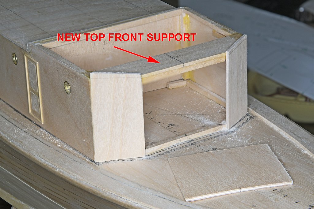
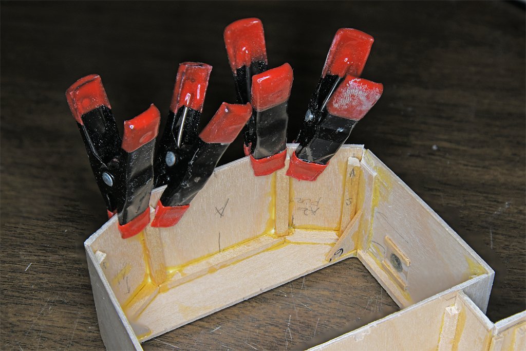
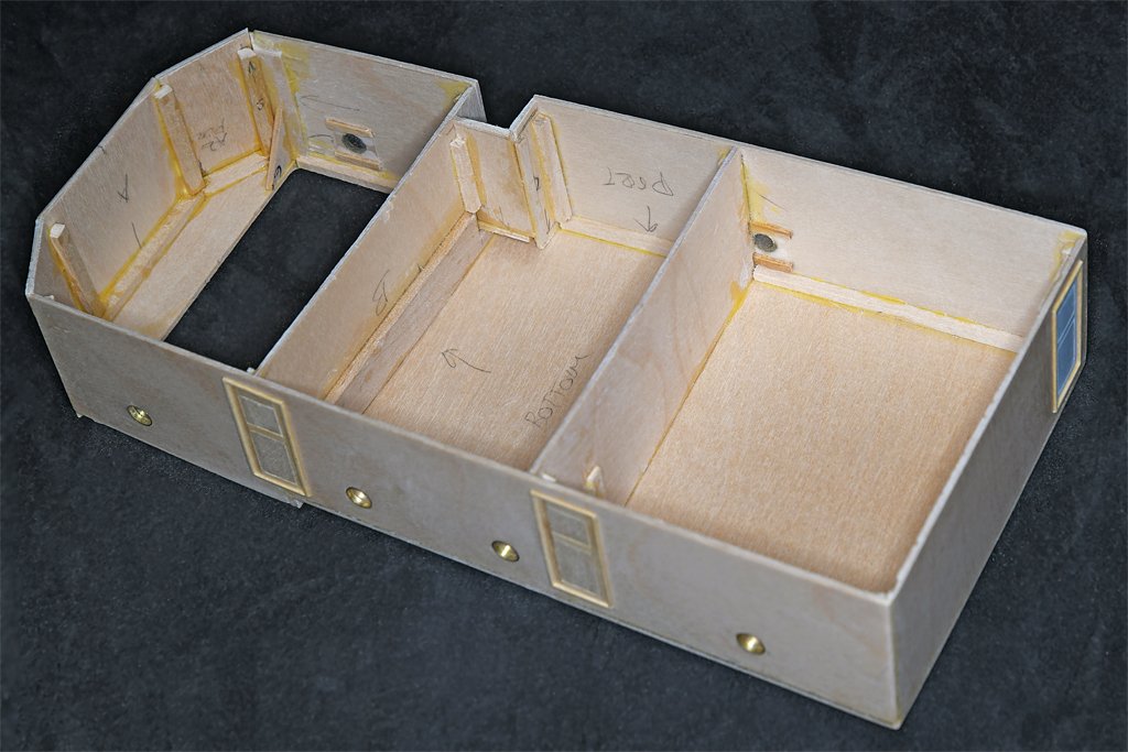
Next I shaped the two side panels to fit the house sides, deckhouse frame and top front support piece. These pieces were cut oversized on all sides and then cut, filed and sanded to fit. Then they were glued into place, and additional support pieces were glued into the angles between the front pieces and the house sides. I wanted these parts to be well supported.
Note that the deckhouse parts are not glued to the deckhouse frame on the main deck. I want to remove the deckhouse while planking the deck, and to continue construction of the O1 level deckhouse and bridge away from the hull.
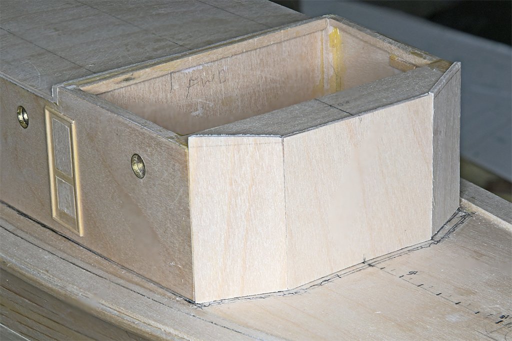
After the side panel glue had hardened over night I shaped the front panel piece to a tight slip fit between the side panels. Then it was glued into place.
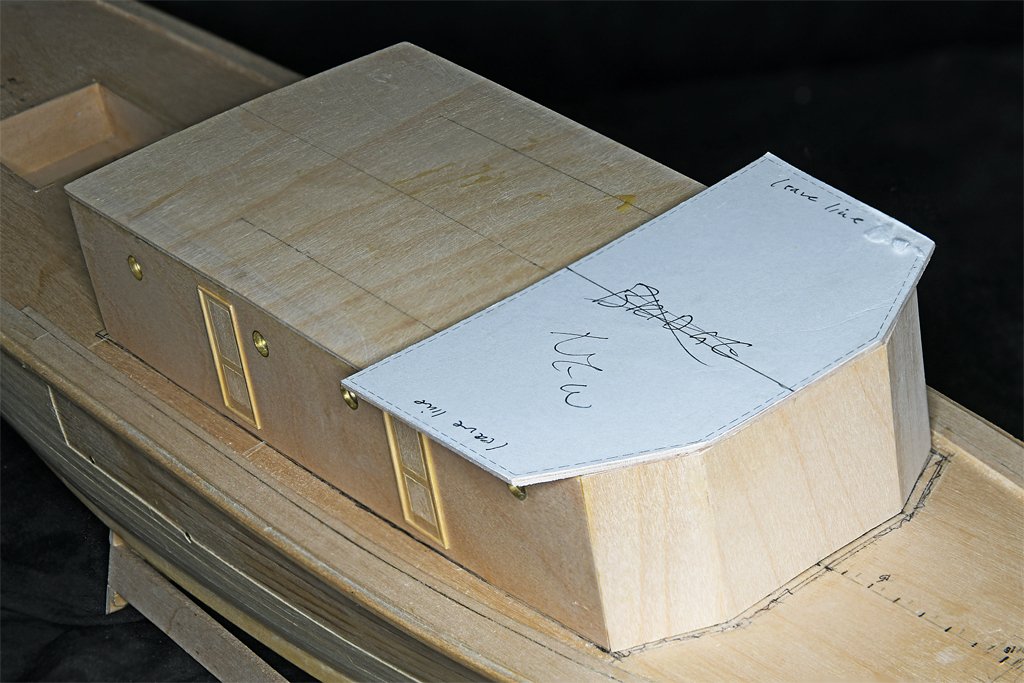
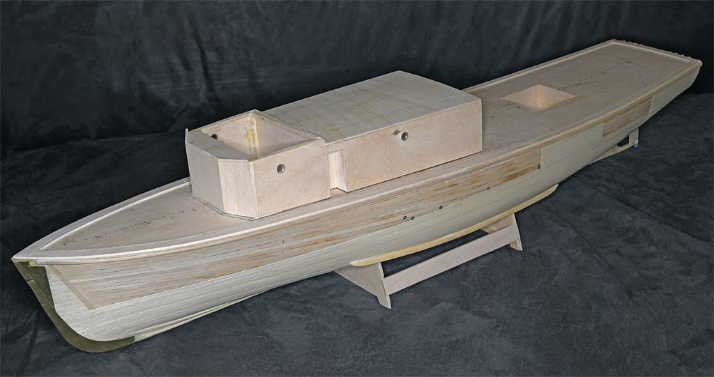
They say the proof of the pudding is in the tasting - or in this case how well the bridge deck fits to the deckhouse structure.
It is as close to a perfect fit as I can get! All of the angles align the way Phil and BuShips intended. I should have assembled it this way in the first place (hindsight is always clearest)!
Now I can start the main deck planking, and while the glue is setting I can do some work on the O1 superstructure (radio room and pilot house) and bridge.
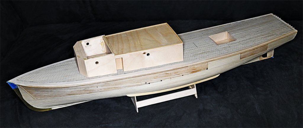
Here are a couple more photos of the main deck deckhouse.
And the deckhouse in place on the hull.
-
Shellac will hold the seizing, but it doesn't adhere to polyester rope. It hardens and appears t hold the rope - as do other glues. But if you put a strain on the rope the polyester will just slip through the glue like it was greased!
- robert952, palmerit and Keith Black
-
3

A deck planking problem - shaping narrow grooves between adjacent planks.
in Building, Framing, Planking and plating a ships hull and deck
Posted
Good ideas!
If you look at the second photo in my original post you will see two hobby knives with #11 blades. The blade on the right has been ground down to make a narrow chisel about 1/2 plank width. I used it to make the initial cut in the nibbing strake where the plank end is nibbed into the strake.
I also used the sides of the "chisel" to scrape the edges of the groove to widen it. It did work, but it was slow going. On the other hand, I did want to remove material gradually until the plank just fit into the groove with a slip fit. So slow was good.
I didn't mention this at first because I didn't want to bias answers.
I do have a set of wood chisels that I use to remove material from grooves (but none as narrow as 1/16 inch). Usually I use a saw to define the width of the channel and a narrower chisel to gouge out material between the saw kerfs. I don't know that I have a steady enough hand to work a plank width chisel between the adjacent planks and keep a straight edge along the sides of the channel.
Any other suggestions?