


Dr PR
-
Posts
2,458 -
Joined
-
Last visited
Content Type
Profiles
Forums
Gallery
Events
Posts posted by Dr PR
-
-
Good progress!
The truss tackles were a bit tricky for me. They work like yard lifts if you pull them too tight, but don't hold the yard if they are too loose. The yard didn't end up exactly where I wanted it, but it was OK.
-
And standing up there you would have to watch out for the boom swinging when changing course!
If it was me I would stand on the deck behind the deck house. I guess you could pull the tiller with the rope.
-
The end of the tiller is over the cabin roof. Where did the helmsman stand?
-
Here is an update on the 8" shear/brake. I have been using it for six months now, and have a few comments about its usefulness. It is in no way a "precision" tool!
Shear
1. As noted above, the stop cannot be positioned closer than about half an inch (12,5 mm) from the cutting edge. If you want to cut narrower strips you have to just take your luck at cutting with any precision.
I have been eyeballing it by marking the cut line on the metal (thin brass) and trying to look straight down the cutting surface to align the line with the cutter. Then I hope the metal doesn't move while I am rotating the handle to lower the cutter.
2. The machine does not have any type of restraints for the metal being cut. You cannot position it accurately and then clamp it down so it cannot move. This is a BIG shortcoming! Larger machines always have a clamp of some sort that holds the metal before the cut starts. This prevents the metal from rotating around the cutting edge during the cut. The amount of rotation with this type cutter is very small as opposed to what happens with scissors type cutters (sheet metal shears), but there still can be a small amount of rotation.
3. You should feed the metal from the back side through the gap between the cutting bars. I have tried feeding from the front, but very narrow strips sometimes fall into the gap below the cutters and disappear into the machine. With thin metal (0.005 inch, 0.13 mm or thinner) is fed from the front the machine doesn't always cut, but may fold the material down between the cutters. I have tried to adjust it so this doesn't happen, but it is hit or miss.
****
The combination of these shortcomings makes it almost impossible to cut strips narrower than 1/2 inch (12.5 mm) accurately. I tried to cut some strips of 0.005 inch brass 1/4 inch (6.35 mm) wide and had to repeat the effort seven times before I got a strip close to the right width with parallel edges. In most cases the cut started the correct thickness but the metal moved during the cut so at the end of the cut the strip was significantly (0.010 to 0.030 inch, 0.5 to 0.7 mm) wider or narrower.
I tried to cut some 1/16 inch/1.6 mm wide strips and that failed every time, varying from half to double the desired width. None had parallel edges. For me this is a real problem because I need to make a lot of narrow strips of thin metals (I can find nowhere to buy such strips). I think a laser cutter may be the only machine suitable for this.
*****
4. When you feed the metal from the rear it passes under the wide bar over the top of the machine about 1.25 inch/32 mm from the cutting edge. You always have about 1.5 inch/37 mm "waste" on each sheet that you can't cut reliably with this machine.
5. There is no mechanism for positioning the stop accurately if you are cutting pieces more than 1/2 inch/12.5 mm wide. There is no way to position the face of the stop parallel to the cutting edge accurately. The stop slides over two bars projecting from the front of the machine with a very loose fit. So the face of the stop can rotate with respect to the cutting edge. When you think you have it in the correct position and tighten the first screw to hold one end in place the stop moves/rotates so the face is no longer in the correct position/distance. Worse still, when you tighten the second screw the stop moves/rotates again so the face of the stop is not parallel to the cutting edge.
You will need to try and try again, carefully measuring the distance from the ends of the stop to the cutting edge to finally get the stop positioned correctly for a cut parallel to the face of the stop. Then, if you are cutting thin metal, the edge of the metal that is supposed to be touching the stop can slip under the lower edge of the stop, allowing the metal to rotate during the cut, producing non-parallel edges!
The stop is almost useless.
****
The cutter has some serious limitations for working with narrow strips of thin material. But it is not useless! With patience and careful positioning, holding the material down with my fingers, I have succeeded in cutting many pieces correctly - but also producing a lot of waste material.
Brake
I haven't used the brake (bending tool) except to test that it will bend metal. You really can't use it for any angles less than about 1/4 inch/5 mm wide because the lower "prism" V notch has edges about that long, as do the upper bending tools. There is no way to position the metal accurately relative to the bending edge. Again, there is a stop on the back of the machine, but it has the same "slop" in positioning as the shear stop. And this stop can be positioned no closer to the bending edge than about 1/4 inch/5 mm.
So the brake can be used for bends with edges about 1/4 inch wide and larger, but it is essentially useless for smaller bends. But for making small metal boxes or chassis it could be very useful.
-
-
Eberhard,
Good catch! The plastic for the cradles is Evergreen Scale Models styrene! Duh!! I have corrected the original post.
I have worked quite a bit with acrylic (Plexiglas) and you are right - it doesn't respond well to cold bending.
I should get a hot air heat (soldering) gun. We used them at work for soldering very high density leads on ICs. They had a small diameter (1/4 inch, 5 mm) removable nozzle that would have been perfect for heating the styrene angles while bending them. And it would be handy for preheating metals for soldering.
- Nirvana, Ras Ambrioso and wefalck
-
 3
3
-
I am working to finish up the "furniture" on the O1 level.
First up was a supply vent that provided fresh air to the engine rooms. I wanted to make it from 0.005 inch (0.13 mm) brass because it looked like it would be fun. I made a 3D CAD model based upon the blueprints, and from that generated the 2D surfaces. These were printed and the parts cut out to serve as templates. They were glued (glue stick) to the brass sheet and then the parts were cut out with scissors - like cutting out paper dolls!
The pieces were soldered together with the same technique used on the smoke stack. It is sitting on a US one cent piece in the right hand photo.


 It went together pretty good. I drilled a hole in the center of the base and soldered in a short 1/16 inch (1.6 mm) brass rod to serve as an alignment pin.
One of the "fun" things about it is that it has a rectangular duct opening, with the long axis running athwartships (port to starboard). But the long axis of the duct penetrating the deck runs fore-and-aft. So I had to make a 90 degree twist without reducing the cross section area of the duct. This is simple - if you have ever worked with HVAC ducts, and you have an entire workshop full of sheet metal bending tools. But it wasn't too difficult at 1:48 scale, except I had to repeat one solder joint seven times before I got everything lined up perfectly. Murphy was having fun that day!
I placed the mounting hole in the deck where the blueprints showed it. This was a bit critical because a life raft was stowed immediately between the vent and the aft end of the deck house with not a lot of spare room. And I had not yet made the life rafts! That was the next project.

I wanted to make the life raft cradle from brass. But the frame was made of 1/16 x 1/16 inch (1.6 x 1.6 mm) "L" extrusions, with a bend radius of only 0.125 inch (3.1 mm). That is only twice the width of the pieces, and there was no way I could bend the small brass pieces without breaking the part on the outside of the curve.
I also have some 1/16 inch styrene "L" angle stock. I tried bending it cold and it worked! But it didn't hold the shape and sprang back at least half the angle. I cut out a wooden form and clamped pieces in place in the form. Then I used a hair dryer to heat the plastic. When it cooled it was almost shaped correctly. I put the pieces back in the form and held a hot soldering iron very close to the bends. After a few seconds I briefly tapped the bend a couple of times (the plastic did melt slightly on a couple of pieces). Then when I took the pieces out of the form they held their shape.


The parts were clamped together one by one and glued using styrene solvent (methylene chloride and trichloroethylene). Nasty stuff - you should have good ventilation if you don't want to lose a few brain cells. The cradles came out OK, but not perfect!
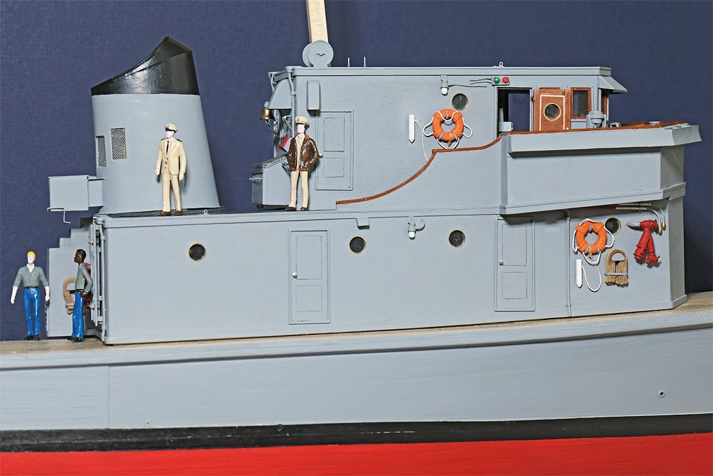
For the life rafts I cut a narrow strip from an old cotton T shirt . It was rolled up and glued together, and the loose ends were cut off to shape it better. Then it was rolled up in some silkspan sail material left over from my topsail schooner build. This was glued around the cotton and then painted white. This was one of the minor differences between the Cape and the Cove. The life raft covers were painted deck gray on the Cove. I have noticed several trivial differences like this between the sister ships. The paint on the life rings is another example. It seems that if the Cove painted things one way the crew of the Cape painted them differently.


The rafts were strapped into the cradles with silkspan straps that had triangular metal fittings (0.013 inch/0.33 mm brass wire) at the ends. On the outboard side of the cradle these fittings passed through eyebolts on the cradle. On the inboard side the triangular fittings were lashed to a ring on a hydrostatic release. The base of the release was bolted to the deck. The dome shaped bit was the pressure release. If the ship sank water pressure would cause the ring to separate from the release, allowing the straps to swing back and release the life raft. At the same time another hydrostatic mechanism in the raft would start it inflating.


Here you can see the two rafts in position on the O1 deck. Three deck lockers will finish out the O1 deck furniture and then I can start on the life rails and life lines.

However, all this work on fiddly bits had been straining my left hand, causing some pain in tendons in my left thumb. Bummer! I can only work a couple hours at a time before the thumb cramps and the tendon becomes painful. Murphy has started a different tactic to screw up this build.
I have orders from the Admiral to cut back on my modeling time and give my hand a rest. Actually I think she is miffed because she thinks I am spending more time with the model than with her! So I think we will take a vacation (the weather looks nice on the coast next week).
- Paul Le Wol, JacquesCousteau, gak1965 and 9 others
-
6
-
 6
6
-
Janne,
Planks were always shorter then the actual hull length except for very small boats. So it was necessary to use several planks along each strake (a line of planks is a strake).
For fairly regular surfaces like decks, planks were laid in a repeating pattern. The ends of the planks were fastened down over deck support beams so the fasteners would have something to fit into. Two planks came together at these butt joints. The planks were laid with several unbroken planks in between each butt join. Where two planks met end to end there would be some number of unbroken planks laid side by side before the next place where two planks met end to end. If there were two unbroken planks between the pattern was called 1 in 3 (one joint and two unbroken planks).
It would look something like this where "---" is the plank and "-|-" is the butt joint:
----------|-------------------------------|-------------------------------|-------------------------------|------------------
---------------------|-------------------------------|-------------------------------|-------------------------------|-------
--------------------------------|-------------------------------|-------------------------------|----------------------------
----------|-------------------------------|-------------------------------|-------------------------------|------------------
It could be 1 in 2, 1 in 3, 1 in 4 or whatever. There are some more complex patterns, but they are not as common.
Hull planking as similar, but the curvature of the surface often called for "creative" planking that did not follow a 1 in N pattern exactly. However, there was an attempt to stagger the butt joints in a regular pattern with several unbroken planks in between. This increased the strength of the hull. Two butt joints were never placed side by side in adjacent strakes.
-
Nice interior detail Craig. Like building a floating doll house. It is fun to add interior detail that will not be seen with a casual look. But peek in at just the right angle and surprise!
-
Yes! And the chem majors' classes were far more demanding than the ordinary chemistry classes - and a lot more fun. Except for the 5 hour organic chemistry labs every Monday, Wednesday and Friday afternoons!! The laboratory had windows, and in the spring we could see the kids playing frisbee on the lawn outside in the warm spring sunshine. That made the labs seem like 10 hours long!
Organic chemistry was interesting. Quantitative and qualitative chem were drier and mainly boring. I thought it was physical chemistry that really separated the wheat from the chaff!
I switched majors to bacteriology (microbiology) in my Sophomore year and had a much better chemistry background than the other micro students.
- Ras Ambrioso, Canute and gak1965
-
3
-
I think the answer to the question lies in consideration of how much wear and tear the item will receive. There is a reason decks are not painted - decks get walked on and things dragged on them. Paint would be scratched off constantly, requiring unending repainting. Usually real decks on working ships were not finished. Navies even holystoned decks to grind off the tarnished surfaces. *
However, yachts and other vessels that see light service do often have "finished" decks.
So will the waterways get the same wear as the deck boards? If so I think they would not be painted.
* Note: An exception to this "rule" is that warships generally have large crews, and "idle hands are the Devil's workshop." So some things do get painted or polished just to keep the crew busy.
-
Valeriy,
Thanks again for sharing your knowledge. I was a chemistry major for a couple of years at undergraduate university and I am quite familiar with saponification. Your excellent results speak well for your methods!
I do use an acetone wash, primarily for dissolving the solidified resin flux from the solder I use. I have 10 pounds (45 kilograms) of 60:40 tin/lead resin core solder left over from the days I was designing electronics equipment and building and testing the prototypes. The fact that I have had it for at least 35 years and haven't reduced the supply much tells that I don't use a lot of it! It is more than a lifetime supply!
I also use a liquid citric acid based flux. It is flux overkill, but it causes the solder to flow into even the tiniest gaps. We used it at work for the high density ICs with half millimeter (0.020 inch) pin spacing.
So first I wash with water to remove the liquid flux. Then I wash with acetone. Then I wash again with soap and water to remove oils and grease. After that I polish with #0000 steel wool and then brush it to remove steel fragments.
The acrylic sealer I used for a primer adhered nicely to the cleaned brass. After drying 24 hours it did not lift off the brass with masking tape. Handling the parts does not damage the painted surfaces.
-
My first thoughts are to experiment with poring melted paraffin onto acrylic (Plexiglas) sheets. You could paint the plastic dark blue-grey on the bottom side to represent the water under the ice.
You probably can chip away the edges of the "ice" sheets to get the broken ice effect.
CAUTION: I haven't tried this so it is just a half baked idea!
- Paul Le Wol, JKC27 and paul ron
-
3
-
I have also heard a "suspicion" that the Titanic helmsman had been Royal Navy (left means right) and the shipping line used the "right means right" procedure. In the confusion the helmsman may have turned the wrong way initially. That was speculation from one of the inquiries about the sinking. But it does call attention to the changes in meaning of nautical terms over the years.
-
I wonder how those early tiller wheels were rigged? Early on the tradition was that if the order "starboard helm (rudder)" was given the tiller would me moved to starboard - causing the ship to turn to port. By the late 1800s different merchant and navy services were changing so that "right rudder" meant turning the rudder/wheel so the ship turned to starboard. Apparently the British Royal Navy didn't make this change until the early 1900s.
-
I had never heard of this arrangement (we didn't have tillers on the ships I was on in the Navy), but watched the Captain use it when sailing on the Lady Washington.
Many (most?) of the sailing ship references describe a different arrangement where there are two separate tackles, port and starboard, that could be hauled upon to pull the tiller to one side or the other. I think this was used on much larger vessels.
-
There is something like this on the Lady Washington.
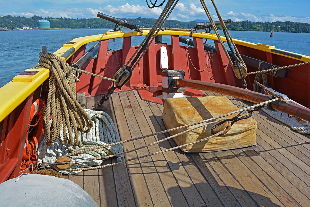
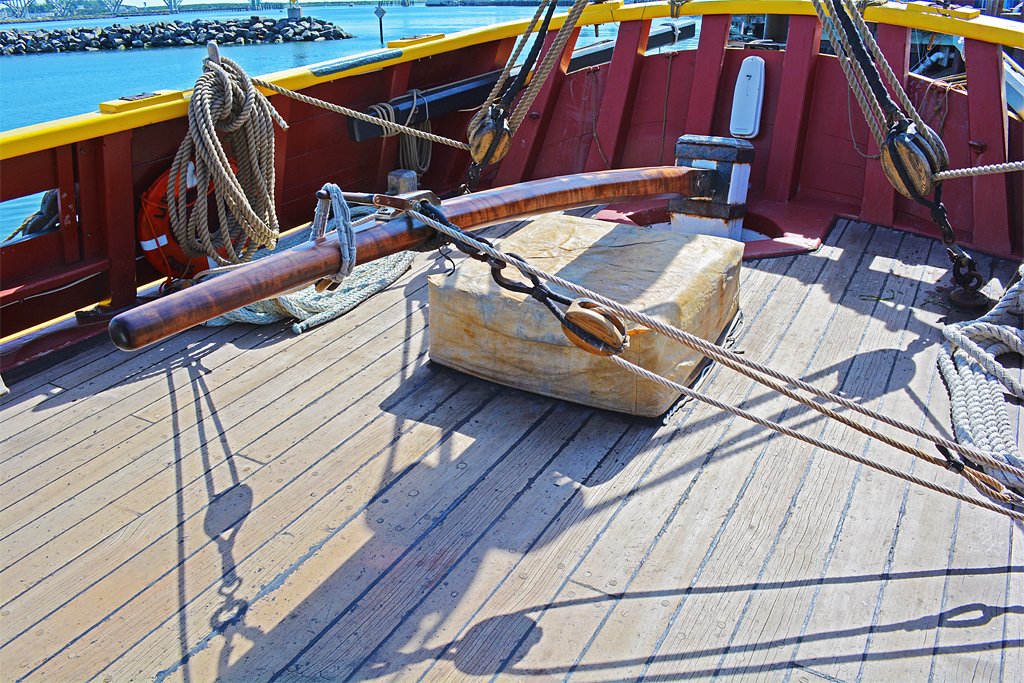
Rather than have sheaves in the tiller single blocks are attached to the tiller. The ends of the line are attached to single blocks at the bulwarks. Where the line crosses the tiller is a lever that can be lashed down to hold the line. A 19th century "iron Mike."
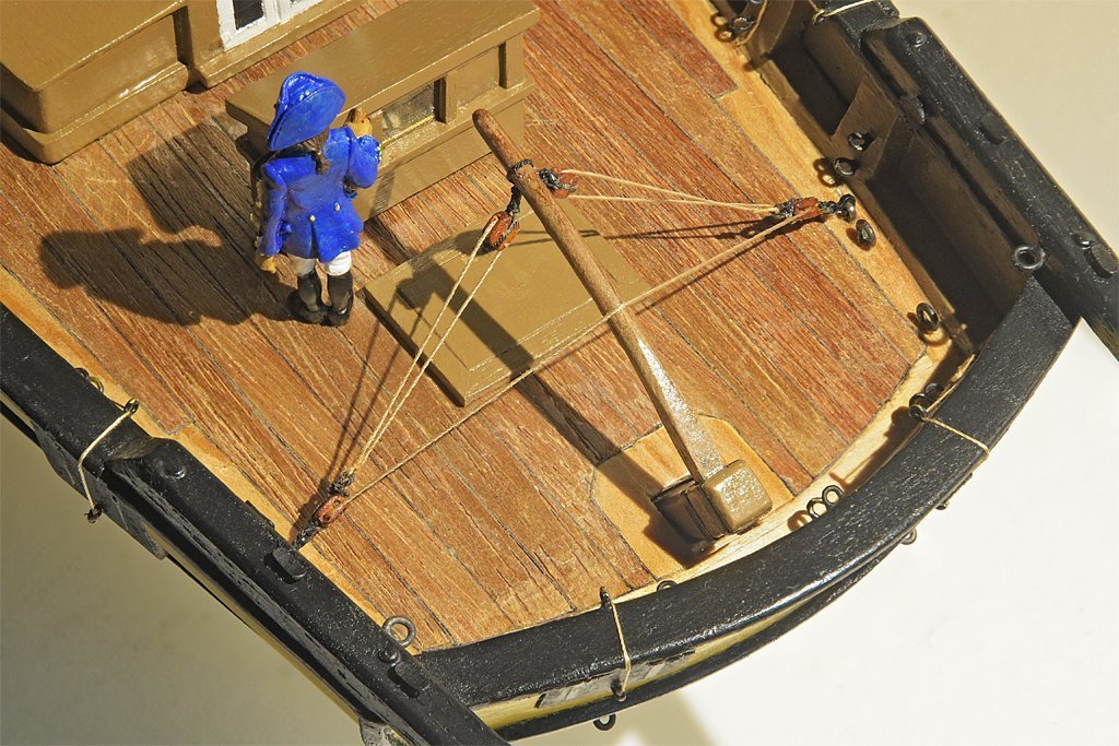 Here is a view of this rig on my topsail schooner model. I did not put the lever on it because I don't know if one was used in the early 1800s.
The belaying pin on the Gjoa serves the same purpose - to lash the rudder at a fixed angle. I suppose the line on the Gjoa might be loose enough so it could be looped over the pin to secure the helm.
Even when the line is not lashed down the friction in the tiller rig serves as a shock absorber to dampen movement. I have read this helped control the rudder when it was being pounded by following seas.
-
Harvey,
I wish you hadn't told us about the mis-aligned seams! Now we will all be losing sleep worrying about it!
-
 The smoke stack is finished (except for the antenna).
I painted the brass with a thin coat of FolkArt all-purpose satin finish sealer. This is what I have been using to seal the wooden surfaces before painting. The instructions on the bottle say it can be used on a "non-porous surface to add slight texture for increased paint adhesion." It is a water-based clear acrylic paint.
After the sealer had dried about 40 hours (delayed due to Christmas events) I painted the black top. After that dried overnight I applied masking tape over the black and painted the grey. The paint flowed on smoothly and adhered to the sealer nicely. Neither the paint nor sealer lifted off the brass when the masking tape was removed.
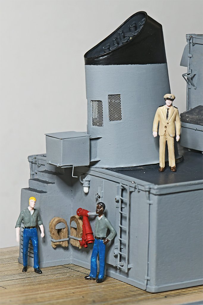
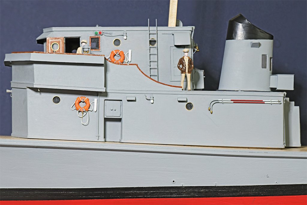
Here is a picture of the fire station at the aft end of the main deckhouse. The life jacket locker hangs directly overhead.
It was an open space away from passageways where the life jackets could be dumped. However, it was just relatively open! The two sailors are standing on a "portable" (removable) deck section that is directly over the four GMC 6-71 main propulsion diesels. An inclined ladder will lead down to the main deck behind the sailor on the left.
When I get around to making the minesweeping gear a small winch will be mounted on the portable deck section. The winch is for handling the large float for the acoustic sweep device. Just outboard to starboard of the winch was a davit, and the acoustic sounder mounted outboard of that. The life jackets would dump on top of the winch and the spaces around it.
A hand grenade locker was positioned where the Captain (in dress khakis) is standing. One of the life rafts will be positioned at the aft starboard corner of the deck house. Forward of that was a pyrotechnic locker.
There was a narrow walkway between the lockers and life raft leading to the top of the vertical ladder. There really wasn't a lot of bare deck space anywhere on the ship.
- Stephen Allen, cotrecerf, TBlack and 10 others
-
13
-
I have the 1989 edition and it is coming apart. I don't know if the later editions would be more durable.
- Balclutha75, GrandpaPhil and Canute
-
3
-
Brian,
Thanks!
This type mechanism was common for life jackets on US Navy ships. The top is a lid that hinges up, allowing life jackets to be tossed in after use. The bottom is a door that hinges down, allowing the life jackets to tumble out on deck. I have studied the blueprints on the Cleveland class cruisers of WWII and the MSI blueprints of the 1950-60s. One thing they have in common is that the lever that pulls down to open the bottom door was held in place by an ordinary US Navy issue 1/2 inch (12.5 mm) fuse clip. Two of these were used in electrical circuits to hold a cylindrical fuse. Just one was used to hold the 1/2 inch diameter life jacket release handle.
The MSI lifejacket locker had to be located above a place on the main deck that was open and easy to get to but not in a passageway. As you will see as the build progresses almost the entire main deck was covered with equipment or stowage lockers. About the only place suitable for the life jacket locker was above the fire hose station at the rear of the main deck cabin. And there was nothing else attached to the rear of the stack which was directly above the fire station, so that was a convenient place to mount the locker.
The Cape had a crew of 19 enlisted and 3 officers. The life jacket locker held 25 CO2 life jackets and 3 "fibrous glass" life jackets. I guess the three fibrous glass life jackets were for the officers. They didn't need a charged CO2 cylinder. There were 6 spare CO2 life jackets in case some didn't work.
The ship also carried two 15 man inflatable life boats and a 12 foot (4 meter) "wherry," a small boat with an outboard motor.
- Canute, Ras Ambrioso, KeithAug and 6 others
-
9
-
Silkspan is the way to go for sails at the smaller scales (1:48 and smaller). The thinnest grade (SIGST001) is approximately scale thickness for 1:48 to 1:72 scale.
When wet it is VERY fragile, but when it is dry it is very tough. It became popular for wing and fuselage coverings on flying model airplanes.
Here are some links telling my experiences making sails from it. There was a learning curve, but the results are pretty good.
In my opinion those heavy cloth stitched sails that come with kits look awful!
- Kenchington and Gregory
-
2
-
The same. If you keep your hands in your pockets there is a much smaller probability of screwing up things. And he's out of uniform. The Captain and XO are wearing dress blues, so that must be the uniform of the day. Fuzz is wearing working khakis (that was our most common daily uniform) and a leather aviator's jacket.
-
wefalck and FreekS,
Thanks for the tips.
I don't know if I can buy Zapon varnish in the US. However it appears to be a nitrocellulose solution. Duco cement is nitrocellulose dissolved in acetone. I suppose I could just dilute Duco with more acetone to make a thin nitrocellulose varnish.
Createx UVLS clear satin is sold here. I have put a bottle in my Amazon cart for my next order.
- Canute and Ras Ambrioso
-
2


Sails on a British Cruizer Class Brig
in - Build logs for subjects built 1801 - 1850
Posted
Even on many larger ships like clippers the royals were just "temporary" sails. The sails were rigged to the yards on deck and then the whole rig was hoisted. They had a halliard for raising the yard and no lifts or sheets. The clews of the sails were just tied to the topgallant yard arms and the topgallant braces controlled both sails.