HOLIDAY DONATION DRIVE - SUPPORT MSW - DO YOUR PART TO KEEP THIS GREAT FORUM GOING! (Only 13 donations so far - C'mon guys!)
×


Dr PR
-
Posts
2,406 -
Joined
-
Last visited
Content Type
Profiles
Forums
Gallery
Events
Everything posted by Dr PR
-

My metal ruler was wrong.
Dr PR replied to modeller_masa's topic in Modeling tools and Workshop Equipment
This reminds me of when I was a Freshman in college. My room mate was an engineering student, because his father was an engineer (drove a locomotive). I has a cheap dime store plastic ruler, and another more substantial ruler given to me by a friend. The heavier ruler had an inch scale and another in picas (my friend's father was a printer). I noticed that if I lined up the two rulers with the zero marks even there was a difference of about 1/32 inch between the 12 inch marks. I asked my room mate to see his ruler - another cheap plastic one - and it gave an entirely different reading! My room mate insisted that his was the correct one. When I asked how he could know he said it was because his "engineer" father had given it to him. He wasn't the sharpest tool in the box and flunked out after one semester. This experience created a doubt about measurements that is still with me today. In the scientific and engineering work I have done I have always known that EVERY measuring device has some error. And this applies to every measurement of length, volume, weight, concentration and so on. The idea of a perfectly accurate measurement is fantasy. The trick is to know how much error, or how accurate the measuring device is, and take that error into account. Even in CAD programs, where measurements may be given to 15 decimal places or more, there is always a tiny round-off error because computers do not have an infinite number of bits in each memory location. And calculation programs like Excel that can calculate to 30 decimal places are plagued by round-off errors in calculations that cause tiny errors that add up over time. I have several ordinary rulers and yard sticks, seven architect and engineering scales, and three calipers. No two give the exact same measurements, although the more accurate pieces disagree much less than 1%. And of course they change dimensions with temperature changes, so each device doesn't always give the same measurement. And then there is the WAY you make a measurement that can generate additional errors. But that's another complicated topic on its own. -
I use a somewhat out of date CAD program that produces poor quality STL files, and many of the things I build are made of zero thickness surface meshes and planes. Lots of leaks! I import the STLs into Microsoft's 3D builder and click the "repair" box and presto - leak free solids! There is one caveat. 3D Builder doesn't like closed circles around openings - it fills them in with a plane, blocking the holes. The solution is to be sure all holes are surrounded by two objects (solids, surfaces, etc.). Then the solid that is generated will have the proper hole in it. I suspect this is only a problem with my CAD program generating incorrect STL files. When I use the Chitubox "Hole Punch" feature to make a hole into hollow interiors there is not false closure over the hole, and I haven't heard anyone else complaining about the plugged openings. **** If you are experiencing leaky STL surfaces I highly recommend 3D Builder. But it is only available for Windows 10-11. CAUTION: Be sure to select the proper measurement units in the top bar in Builder. STL files do not contain any measurement unit information. Builder may default to the wrong units - it scaled my millimeter unit parts to centimeters, and everything was 10x the correct size until I realized what was happening. Also, I HIGHLY recommend using the Chitubox "Hollow" feature. I was designing objects in my CAD program with manually created interior hollow spaces, trying to achieve a uniform wall thickness. It was a lot of work! Than I just redesigned a part that wasn't printing well with only the exterior surfaces. I used the "Hollow" feature to generate parts with 2mm thick walls, and the program added the interior lattice supports needed for correct printing. Then I "punch" holes in surfaces that would normally be hidden (bottom, etc.) to let resin drain from the interior. The results were a lot better!
-
Valeriy, I am saddened and angered at what is happening to your country. I hope you, your family and friends are safe and come through this unharmed.
-
Fellows on The Ship Model Forum have been experimenting with printing large flat surfaces without any supports - just flat on the print platform. This produces very flat thin pieces like decks. The initial long exposures for the base layers will create a small wider bead around the part on the print platform, but this is easily filed/scraped/sanded away. Because the contact surface on the plate is so large you don't need many long exposed base layers. Some have made successful prints without them.
-
Jan, Howard Chapelle actually describes this in "The History of the American Sailing Navy" (W. W. Norton & Company Inc., New York,1949) on page319. "... the pivot bolt was placed on top of an upright post, or column ... The height of the pivot post ... was decided by the height required to permit the gun to fire over the bulwarks." On vessels with high bulwarks the guns had to me mounted very high. He says "This mount was not particularly strong, and for some years it was confined to the use of pivoted carronades. ... This type of pivot mount became popular in all armed schooners, even merchant vessels, and particularly in slavers." Casey, You are welcome. But I must add a word of caution: You are very close to falling down the rabbit hole!
-
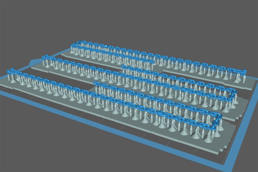
Pat, Nice railings. I have been thinking about how to make railings for the OK City model for about 12 years. They have extremely small diameter sections. I have been planning the purchase of a small high tolerance milling machine just to drill 0.008" holes through 0.013" brass wire to make the stanchions. Even with a very good mill I foresee a lot of broken bits and scrap pieces. There are between 450 and 500 stanchions that will have to be prepared! **** I ran the chain prints again, using a 0.04 mm step size and 3 second exposure (as opposed to the earlier 0.02 mm step and 2 second exposure). Half as many exposures but 50% longer exposure time. The design diameter of the chain "wire" was 0.66 mm. The horizontal links came out 0.75 mm to 0.84 mm thick, 14% to 27% oversized. The vertical links were 0.63 mm to 0.66 mm, or 95% under size to 100%. Most of the links were free or slightly fused, but when I gently twisted the chain around the long axis almost all of them separated. So this was near the limit for getting a flexible chain. However, I printed three chains and one did not print completely. I think the 2 second exposure was better because it have thinner vertical layers - even though I was printing layers twice as thick as before, so only half the number of exposures. I can see no visible difference in the surfaces of the 0.02 mm vertical step and 0.04 mm step parts, so 0.04 mm is adequate. Actually, these things are so small that if there was a difference it wouldn't be noticeable. There really wasn't much difference in the thickness of the vertical links between the two runs, so the longer exposure time made no difference there. But it certainly did make the horizontal link thickness greater even though there were only half the number of exposures. And that was causing the links to fuse. So it looks like the optimal settings for these tiny parts 1s about 0.04 mm step size and 2 second exposures with the Anycubic Basic Grey Resin - which they call "Colored UV Resin" on their web site - on the Photon Mono printer.
-
Casey, Welcome! I looked up the EMMA/Sidmouth kit. It is a Baltimore clipper, or topsail schooner. The gun on the centerline is a pivot carronade. Carronades were large bore short barrel guns that had a short range but threw a large shot (or a lot of shrapnel, grape shot, etc.). They could do a lot of damage at short range. But their main advantage is that the short barrel made them a lot lighter than a long cannon, and topside weight is always a problem in ships, especially small vessels like schooners. I am building a very similar Baltimore clipper and have been researching these vessels for several years. Here are some links for topsail schooners: https://modelshipworld.com/topic/19611-albatros-by-dr-pr-mantua-scale-148-revenue-cutter-kitbash-about-1815/?do=findComment&comment=598658 https://modelshipworld.com/topic/25679-topsail-schooner-sail-plans-and-rigging/?do=findComment&comment=750865 https://modelshipworld.com/topic/30234-topsail-schooner-belaying-plan/?do=findComment&comment=862302 https://modelshipworld.com/topic/27410-small-ship-anchor-handling/?do=findComment&comment=787942 https://modelshipworld.com/topic/29060-schooner-heads-1700s-through-1800s/?do=findComment&comment=829120 My prime reference for Baltimore clippers is Howard Chapelle's "The Baltimore Clipper," Edward W. Sweetman Company, New York, 1968. Lennarth Petersson's "Rigging Period Fore-and Aft Craft" (Naval Institute Press, Annapolis, Maryland, 2015 is a nice reference for rigging topsail schooners. Chapelle's "History of the American Sailing Navy" (W. W. Norton & Company, New York, 1949) page 319 discusses pivot carronades on schooners. They were quite popular about the time of the War of 1812. Chapelle's "History of American Sailing Ships" (Bonanza Books, New York, 1985) tells a lot about the development of Baltimore clippers and topsail schooners in general. Chapelle's "The search for Speed Under Sail" (W. W. Norton & Company, New York & London, 1967) goes into the historical detail of the development of the fast schooner. Karl Heinz Marquardt's "The Global Schooner" is one of the best references for schooners. It is the "Lees" reference for schooners. James Lees' "The Masting and Rigging of English Ships of War" is generally considered one of the nest reference for sailing ship rigging, but it does not mention schooners. If you want to learn about nautical terminology and rigging ships here are some references: Falconer's "Universal Dictionary of the Marine," 1769 is a good dictionary of nautical terms. It is available online on Google Books and some other places. Steel's and Biddlecombe's "The Art of Rigging" has a dictionary of masting and rigging terms. They are available online here: https://thenrg.org/resource/articles Biddlecombe "The Art of rigging" (1925, Echo Point Books & Media LLC, Brattlleboro, Vermont) is also available in print. Darcy Lever's "Young Sea Officer's Sheet Anchor" (Algrove Publishing Limited, 2000) has a very good description of masting and rigging terms with excellent illustrations. And if you really get into schooners and want to know more there is Chapelle's "The American Fishing Schooners" (W. W.Norton & Company, New York and London,1 973). By now you should be guessing Howard Chapelle did a lot of research on schooners of all types. So there is everything you wanted to know about schooners and a lot more!
-
The "wire" in the CAD model anchor chain is 0.6615 mm diameter and a circular cross section. The printed parts are oval in cross section, 0.62 to 0.65 mm on the vertical and 0.71 to 0.74 mm on the horizontal. So I am getting about a 2% to 10% reduction in the width on the film, but an additional 10% to 12 % thickness on the vertical. I expected the parts to be a bit too thick on the vertical dimension. From past experience I knew that the very thin parts are translucent so additional resin gets cured on the upper surfaces of very thin slices. But I can't explain why the parts were thin on the horizontal dimension. I would expect resin to be cured over the entire pixel width but this apparently is not happening. Increasing the exposure time probably would increase the horizontal width, but it might also cure more resin in the vertical dimension. Increasing the step size would reduce the total exposure time, and perhaps reduce the vertical thickness. I am happy with the results I got - no one (except me) is going to be taking a micrometer to the chain on the model. But I might try printing them again with a different step size and exposure time. With a model diameter of 0.66 mm the 0.02mm step size gave 33 slices and exposures. A 0.03 mm step size would give 22 slices, 0.04 mm would give 16 and 0.05 mm would give 13 slices. So I might try the 0.04 mm step size to halve the number of exposures and try to reduce the vertical diameter, but use an exposure time of 3 seconds to expand the horizontal width a bit. **** The reason I want to control the printing better to get a circular cross section is that there are many yards/meters of life rails on the model. They real parts were made of pipe 1.25", 1" and 0.75" diameter. At 1:96 this comes out to 0.013", 0.010 and 0.008", or 0.33 mm, 0.25 mm and 0.20 mm. This is less than half the chain link "wire" diameter. I have successfully printed 0.20 mm diameter pieces, but they are extremely fragile. I really don't want the parts to come out any smaller, but 10% oversize would be OK. But I want them reasonably close to cylindrical. I have been reading up on some of the flexible resins. I would think these would be less susceptible to the accidental bumps that happen while assembling models. But several sites say they are not suitable for thin walls, and the minimum thickness should be 1 mm, or 125 times the thickness of the smallest pipes! Furthermore, because they are flexible they may not separate from the plastic film evenly and become bent while printing. This is also probably true for regular resins, so lots of supports will be needed!
-
Pat, Your DUKW "duck" drive train brings back memories. I grew up in Hot Springs, Arkansas. It is a tourist trap - it had about 270 hotels and motels (individual businesses, not rooms) when I was a kid in the 1960s. The town is surrounded by lakes on two sides (actually it has grown around the lakes these days). There was a company with a fleet of "ducks" to take tourists on rides around the lakes. I never rode on one. But I worked for an auto parts house in high school and college driving a delivery truck. The DUKWs had a bunch of universal joints in the drive train (I don't remember the actual count but I can see eight in your model), and they wore out fairly quickly. And of course there were the engines and lots of other parts. I made a delivery or two every week to the "duck barn." Hauling the engine blocks back and forth for rebuilding in our machine shop was the most difficult part. I think they are still using some of those things that are older than I am!
-
Kevin, So far I have used only the Anycubic Basic Grey resin. I would like to try other resins so please post your results as you try new types. From posts other people have made on the Ship Model Forum (lots of scratch built modern vessels) I know there are some resins that are flexible when cured, and do not break as easily as the harder more crystalline resins. These are useful for very thin things like life rails that get bumped often while building the model . I have yards of railings on the Okie Boat model and have been wondering how I can make them to scale. The thought of making thousands of solder joints too assemble the railing out of 0.008 and 0.010 inch diameter wire is not appealing! I do not think railings that thin printed with the Anycubic Basic Gray will stand up to any accidental bumps. It is pretty brittle when cured. Pat, I wonder if the white crud on the chains is the result of over curing? Some resins (including Anycubic Basic Grey) turn white and crusty if overexposed - I speak from experience! Since the chain is small and very thin I used only a two minute exposure, then turned it over, and gave it another two minutes. And I was afraid four minutes might be too long. I am using a 20 Watt 405 nm light with twelve UV LEDs and a small light powered turntable. They are enclosed in a box lined with crumpled aluminum foil to create surround lighting. For large parts I use 5-10 minute exposures. I was surprised to see that very little material from the supports was left on the chain. There was some, often because I didn't get a clean cut when freeing the chain from the supports. I spent an hour or so examining every link (on three chains) and cutting/scraping the tiny bits of residue. There really wasn't much to remove. Actually, I have been using Chitubox's "medium" supports but I do think I reduced the contact diameter to the smallest size for this job. Another fellow (on the Ship Model Forum) who printed a small chain like this said he just pulled it off the supports and it came away like a zipper opening. I wasn't that brave, but most of the links came free of the supports just as I was handling the thing while clipping some of the supports. I was able to remove the chain from the supports with just some sharp pointed tweezers. Just a slight twist on a link caused it to separate from the supports, and that usually freed the neighboring links too! The first (failed) print had two supports under the vertical links and four (two each side) on the horizontal links. This left lots of residue at the points the supports contacted the links. But after separating the fused chain from the supports I decided that I really needed half that number for the second attempt, and it worked fine.
-
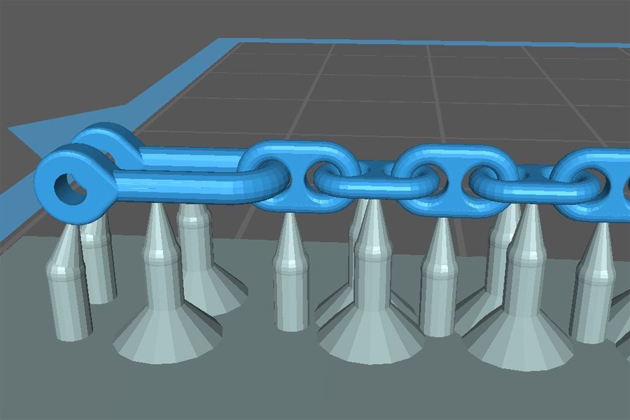
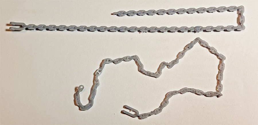
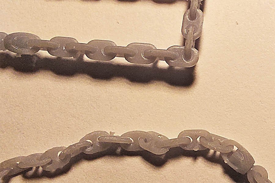
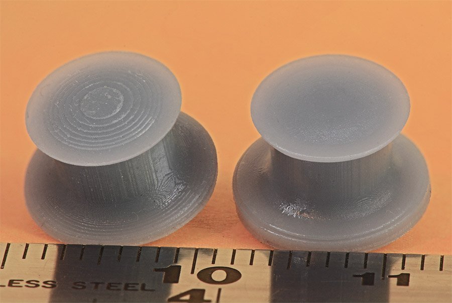
Here is another example of playing with the printing parameters to get the job to come out right. I decided to try to print the anchor chain for the OK City. I have never been able to find stud link chain the right dimensions for the 1:96 model. The links are pretty small - 3.95 mm x 2.4 mm (0.155 x 0.094 inches) with a "wire" diameter of 0.66 mm (0.026 inches). In Navy terms the round bar that the links are made of is called "wire." The wire for the 1:1 links was 2.5 inch diameter. These are images of the supports that I added manually in Chitubox (the automatic support add function placed too many and they were somewhat haphazardly positioned). The first attempt used 0.01 mm vertical step size, 3 second exposures and the Chitubox Settings/Advanced anti-aliasing feature was enabled. The print was a failure - all the links were fused together. I figured there might be several causes. The 3 second exposure was curing more resin around the parts. Using 0.01 mm step size meant more exposures. And the anti-aliasing function might be blurring the image a bit and causing some exposure in the space between the links. Next I used 0.02 mm vertical steps to halve the number of exposures, and 2 second exposures (the minimum exposure time recommended by Anycubic for the Basic Grey resin and the Photon Mono printer). I also disable anti-aliasing. Success! The top "chain" has fused links. The lower chain has every link separate as they should be. Here is a close-up of the chains. The upper chain links are smoother because of the larger number of steps and possibly because of the anti-aliasing. You can see the cured resin in the gaps between the links. You can clearly see the open gaps between the links in the bottom chain They might be a bit rougher than the top chain, but they are definitely good enough! Now I have to figure out how to paint them (black) without gluing the links together. A really nice thing about being able to print the chains is that I can include the anchor shackle and a swivel link, and use the correct number of links between them to get the right configuration for the ship.
-
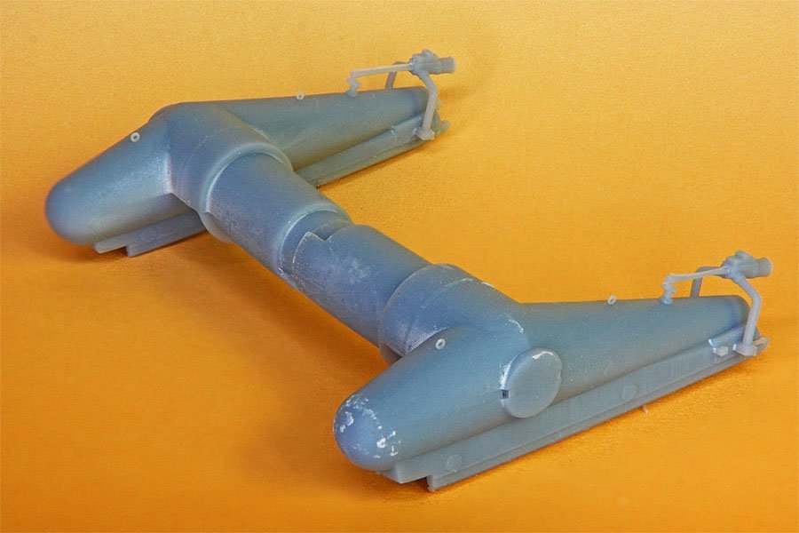
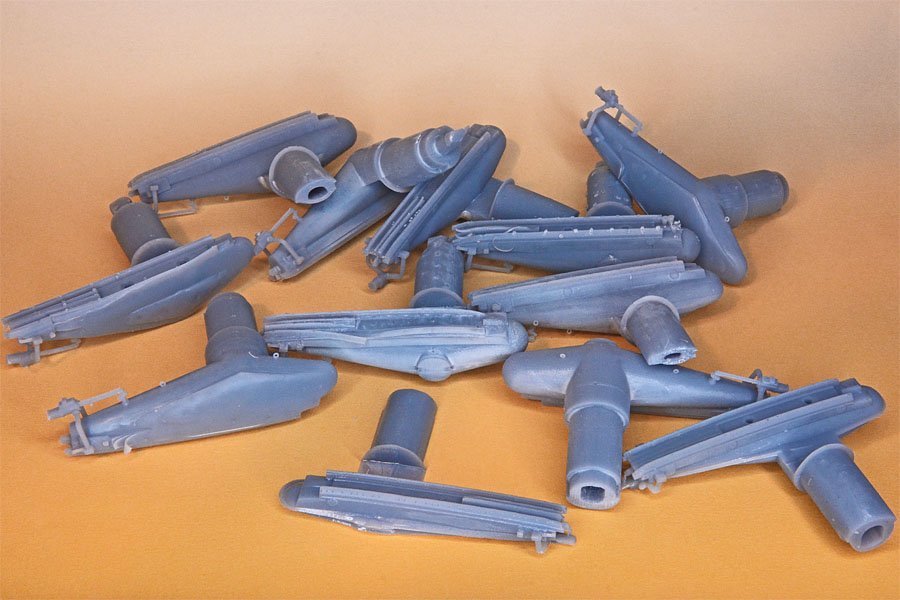
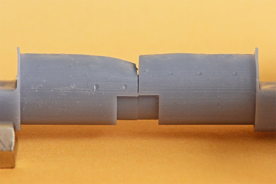
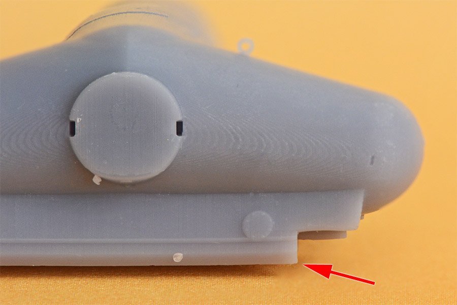
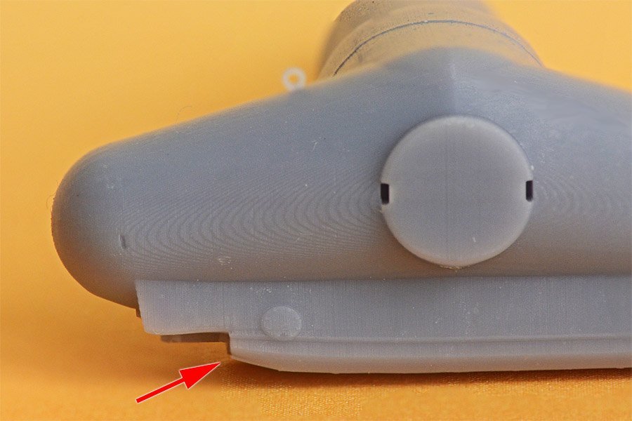
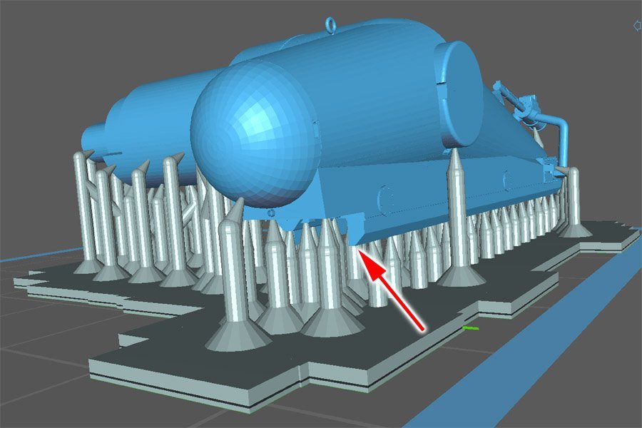
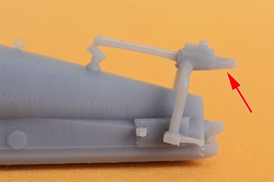
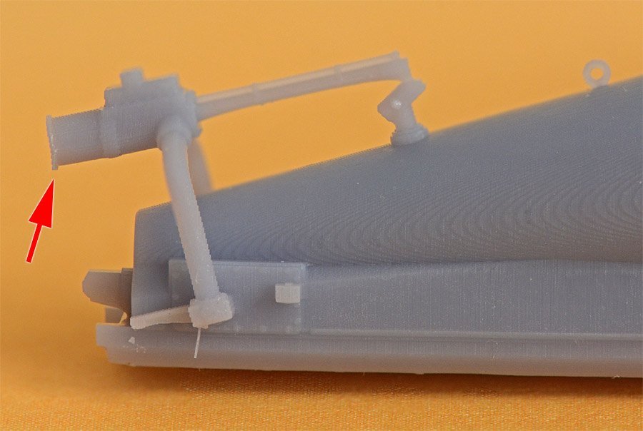
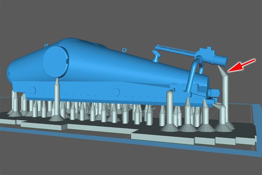
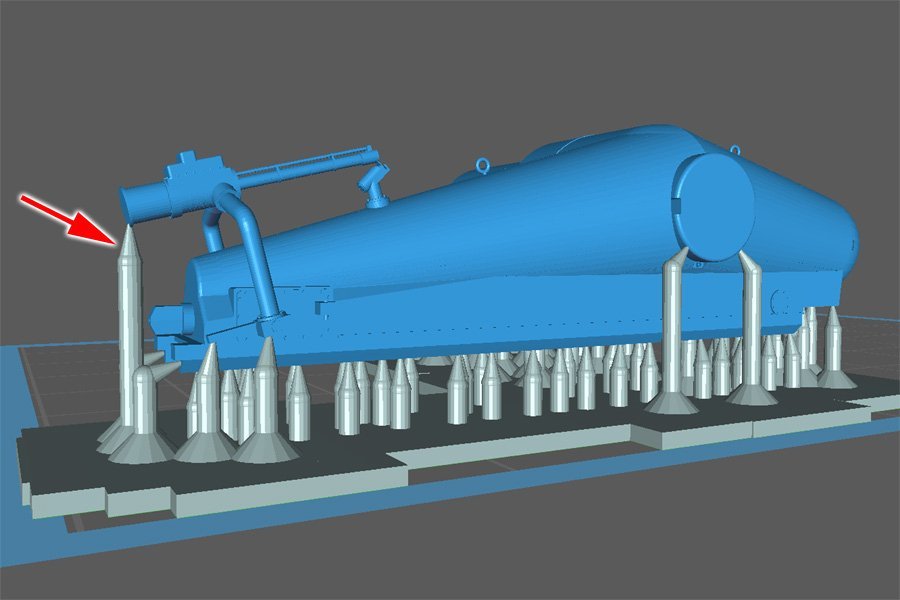
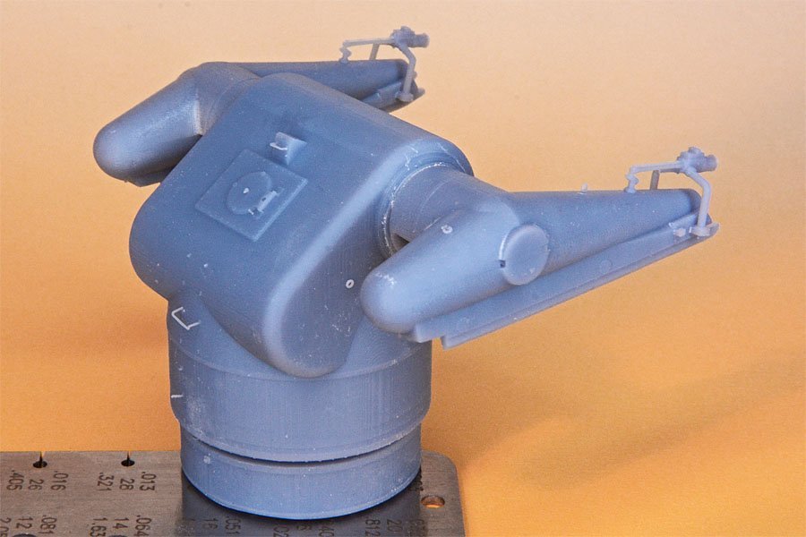
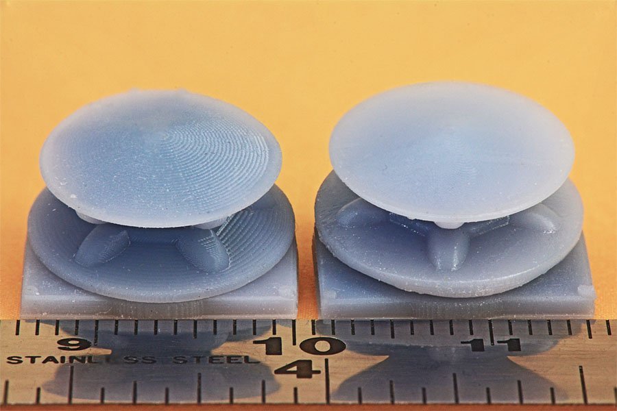
PRINT FAILURE PART 2 The launcher arms turned out to be my nemesis! The arms are printed in two parts, right and left. They slip into openings in the launcher body and fit together in the middle using the same "lock and key" arrangement in the launcher body and base ring. Stops molded into the interior of the launcher body and grooves in the launcher arms limit the angle of rotation of the arms from horizontal to plus 55 degrees just like the real thing. The left photo shows some successful parts. Very tiny details were printed correctly. The photo on the right shows some of the 14 print failures during the learning process. I finally got two usable prints of each arm - a not too spectacular 22% success rate! I first tried printing them horizontally. After a lot of failures and suggestions from more experienced people, I tried printing them vertically. No joy! Here is an example of the support arrangement for the vertical prints. They were total miserable failures! So what was the problem? Not enough supports, of course. The problem is that Chitubox and I were putting a lot of supports along the very bottom of the part, But because the arm is shaped like two truncated cones attached at their base, the cross section are increases with each slice. And that means the forces involved increase. So what is needed is more supports for each printed slice. A LOT more. But there is a way to reduce the slice contact area. Chitubox has a hollowing feature that works very nicely. And it also can add internal supports so the top of the hollowed object also has plenty of support. This is an image from Chitubox showing a cross section through the hollowed launcher arm. The slice surface area is the darkest blue layer. You can see the internal "X" braces the program adds. This solved most of the problems. I also used Chitubox's "Hole Punch" tool to add drain holes to allow resin to escape from the interior cavity and avoid suction caused as the part rises from the plastic film. The original parts were solid and as the print progressed the s;ice surface area increased and increased until the supports failed. But with the hollow parts the surface area was much smaller and the supports held. But this wasn't the end of my problems! This is an example of one of the failures. The interior part of the arms is supposed to be cylindrical and you can see how the ends of these arms "collapsed." But it wasn't a collapse - the failed surfaces were attached to the supports. If the supports failed why didn't the succeeding layers remain stuck to the film? After the job was finished there was nothing on the film! Mystery #1. This is my guess how this happened. First, as the separating forces increased with each pass, the supports broke, leaving the printed part unsupported on the ends. When the print platform rose to print a new layer the separating force between the plastic film and the printed surfaces pulled the thin flexible print layer down, adding a curve to the surface. When the print stage descended this downward curved part contacted the plastic film and prevented more resin from filling the gap. So the parts still attached to the supports printed the correct thickness, and the part on the end was too thin. At each subsequent pass the existing curved printed part served as the support for a bit more of each slice, extending the curved part. Weird! The solution was to add a lot more supports under the end and inside the "keyhole" to be sure there were enough supports as the print proceeded. But that wasn't the end of the problems! The ends of the launcher rails are supposed to be squared off like the photo at the left. But many of the failures were as shown on the right. Both parts were hollow, and they had the same number of supports! What gives? This was actually a simple fix once I understood the problem. On the part at the left there is a support right at the bottom front end of the rail. This supported the print so it didn't warp. The right hand part also had a support near the front bottom of the rail, but not right at the front. So the rail flexed as it was printing - exactly like the failure in the cylindrical parts of the arms. I added a support at the end of the rail and it printed correctly. And then there was this problem: Same problem. An overhanging part failed to print in one case but not in the other. Looking at the supports tells the story. In this case it was not Chitubox's fault. The picture on the right shows the correct default support provided by the program. But I moved the support on the left because it left a bit of the tip of the support on the flange of the overhanging part. Duh! But again, there was nothing left on the plastic film after the print. So the successive print layers remained attached to the printed part but just flexed with the separating forces. After the support connected to the part the rest of the part printed correctly. This funny thing on the back of the launcher arm was the "Emergency Igniter." If the TALOS booster failed to ignite when we pulled the trigger we had a real problem! The 4000 pounds of class B explosive in the booster accelerated the 7500 pound booster/missile from zero to Mach 2.2 in 5 seconds, at a distance of 8 miles! It made fuel dragsters look like kiddie toys. The flame from the booster was 75-80 feet long. It was a real blowtorch, and we definitely didn't want that in a magazine containing 200,000 pounds of high explosives!! The solution was the Emergency Igniter arm. The cylindrical can at the end held a black powder charge. The assembly could be rotated back and down, and the arm extended to shove the powder charge into the booster nozzle. Then we pressed a button igniting the black powder and that ignited the booster. End of problem (unless the igniter failed to light). And the end (I hope) of my printing problems is the awareness that EVERY part must have a support, especially at the ends, and the total supports must be capable of withstanding the separation forces as the part frees from the plastic film.

-
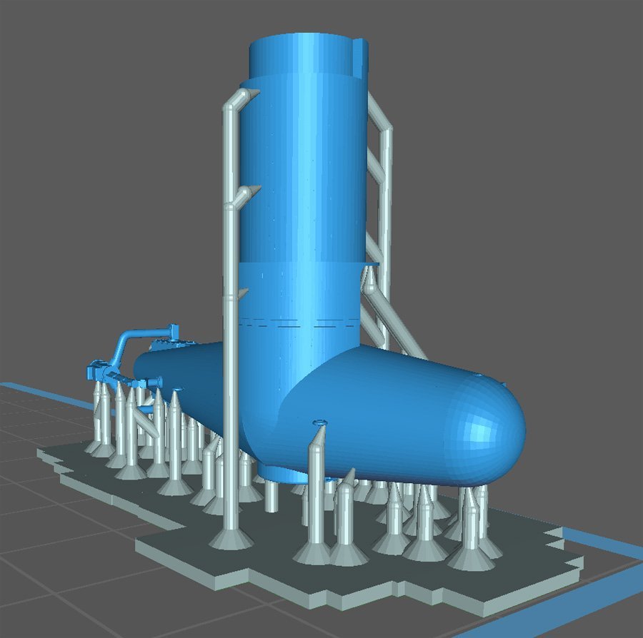
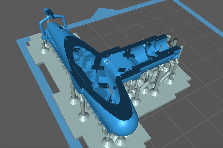
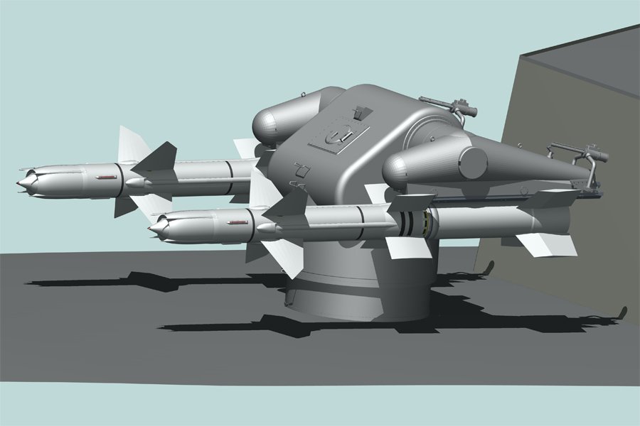
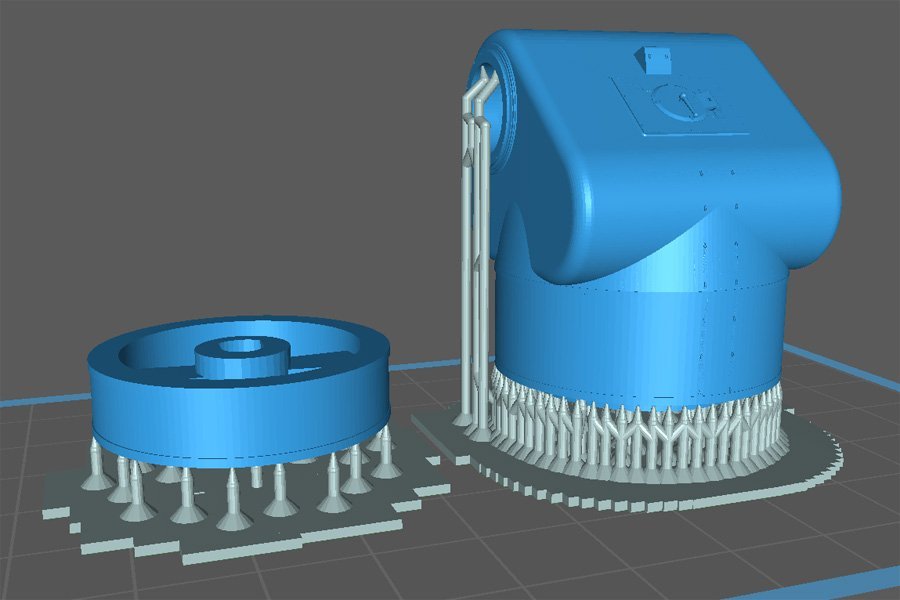
PRINT FAILURES OK, take a deep breath! This is complicated. As I said at first, I had a lot of beginner's luck just using default values for the printer and resin. But that didn't last. I finally met my nemesis! This is the TALOS missile launcher on the USS Oklahoma City CLG-5. My CAD model is on the left and the 3D print is on the right. I had a LOT of print failures with this thing before I learned a few important tricks. I still haven't ironed out all the problems, but here is food for thought. On the left is the base ring and trunnion support (launcher body), showing the "lock and key" arrangement to allow the launcher to rotate on the base without falling off. Both pieces are cylindrical and hollow, with thick walls. On the right is a picture of the default support arrangement that Chitubox created. Notice the very large number of supports under the trunnion support and the small number under the base ring (using the same slicer settings). The trunnion support prints every time with no problems. The base ring failed to print every time! The reason for the failure is VERY important! The printer works by lowering the print platform so there is a very thin gap between the platform and the previously printed layers and the thin UV transparent plastic film at the bottom of the resin tank, right above the LCD display. The gap between these objects is the vertical step size, generally between 0.01 mm and 0.05 mm. Liquid resin in this gap is exposed to UV light to harden the resin and create another "slice" layer on the printed part. Then the print platform is raised to allow more resin to flow in, and then lowered to set another vertical step gap for the next exposure. When the resin is exposed it hardens and sticks to both the part being printed on the print platform and the plastic film at the bottom of the resin vat. Then when the platform rises a tug of war ensues between the print platform and the plastic film. Something has to give, and it is supposed to be the bond between the printed part and the film. The first few layers that are printed are exposed much longer than the rest of the part. This creates a strong bond between the printed layers and the print platform. In addition, the bases of the supports are much larger than the supports themselves, increasing the contact area between the printed part and the platform. The contact area of the support bases must be greater than the largest slice section area if the platform and printed part are to win the tug of war. So be sure to use fairly large bases for each support. In the picture above I have used "cubic" (actually square) bases 15 mm x 15 mm. This size is assignable in Chitubox. It is always the weakest part that gives. And in some cases it is the connections between the supports and the printed part. Each support can take only so much stress, and if that is exceeded it breaks. In the case above, there were a lot of supports under the launcher body, and they were enough to take all the stress of pulling the printed layer from the plastic film. But there were not enough supports under the base ring, so when the platform lifted the force of pulling the printed layer away from the plastic film was too great and all of the supports broke. When this happens, after the print is done you find the base of the supports stuck to the print platform and a part-shaped blob stuck to the plastic film. After I manually added about 4x more supports in Chitubox I finally got a correctly printed part! The moral of the story is that you have to have enough supports to take the strain. But of course, there is more. The force necessary to separate the printed layer from the plastic film is directly proportional to the surface area in contact with the film. And the number of supports needed to take the strain is equal to the total force divided by the amount of force force needed to break one support. So if the total force was 100, and each support will break with a force of 2, then the number of supports needed is 100/2 = 50. The larger the surface area, the larger the number of supports needed. In the case above the launcher body walls were thicker than the base ring, meaning that the forces would be greater, so Chitubox added a lot of supports. But for some reason the program guessed the necessary number of supports for the base ring too low, and they weren't strong enough to take the total force. You can't always trust the software (more about this later)! However, there is no way to predict the actual forces involved with the information supplied with the resins, and we don't want the complications, expense and time of setting up and running a laboratory experiment to determine these things. But I think it is a safe bet that you can just divide the surface area of the largest print slice by the cross section area of the supports and get a good idea. Chitubox allows you to set the contact diameter where the tip of the support contacts the printed part. Contact area = diameter x pi (3.14159). And you should be able to determine the cross section surface area of the printed part in your CAD program. So divide the slice surface area by the support contact area to get the minimum number of supports needed. But even I am not anal enough to want to do that, so I just start with Chitubox's default supports and if it looks like there aren't enough I add more. If the print is a success I guessed right, and if not I start over and add even more supports. This is called a learning curve! But that s just the start of this problem. I did manage to print the base ring and launcher body to my satisfaction. But the launcher arms were another thing!
-
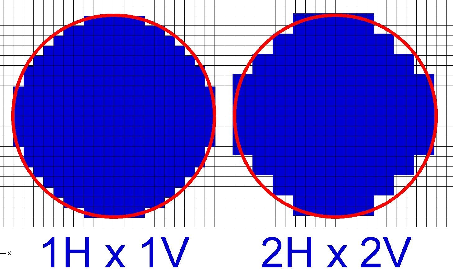
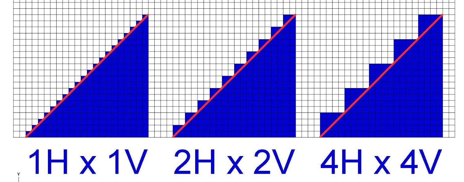
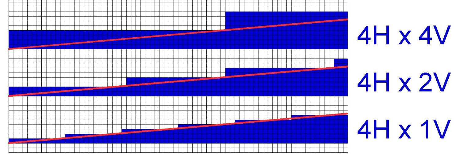
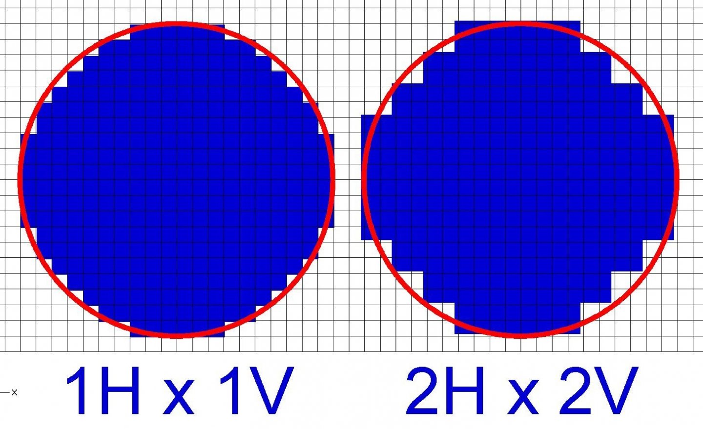
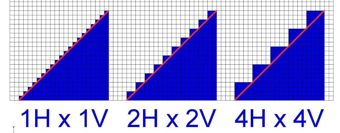
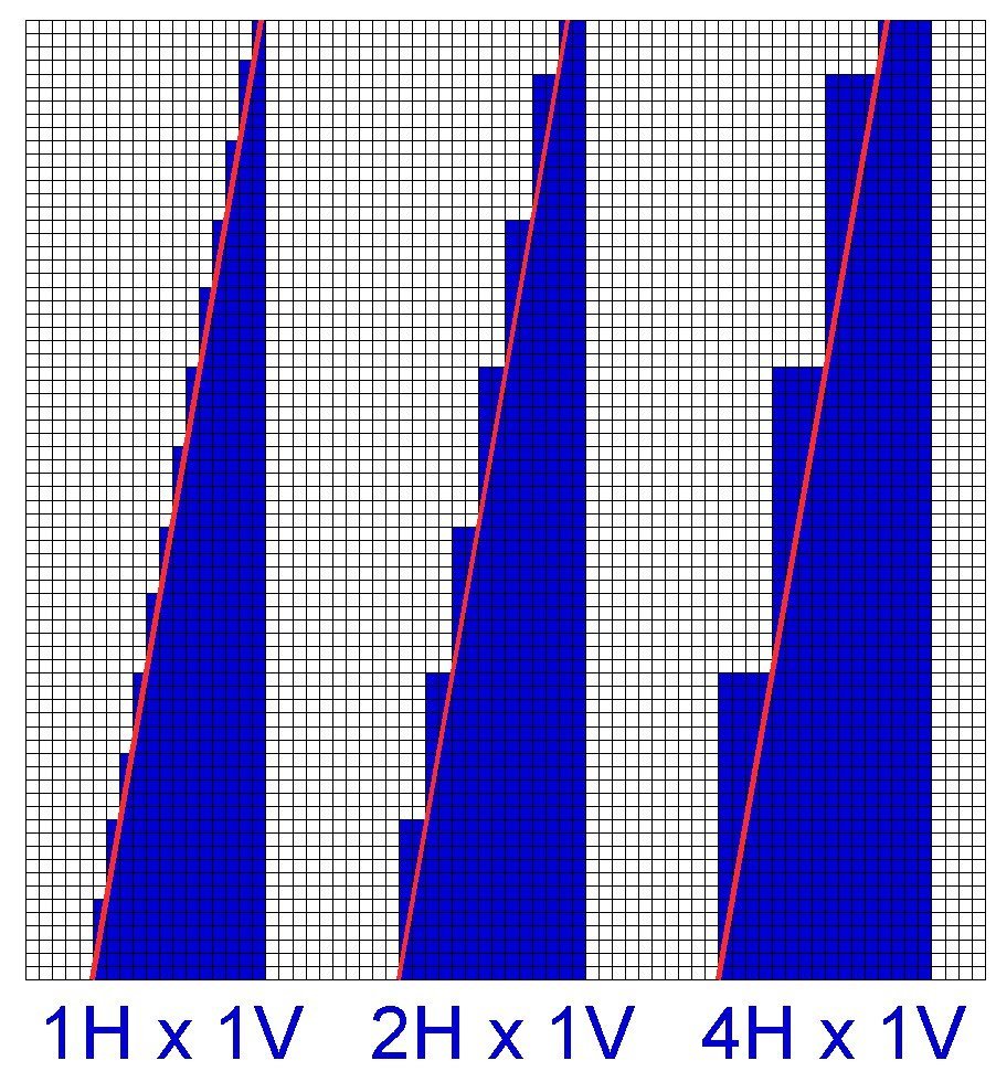
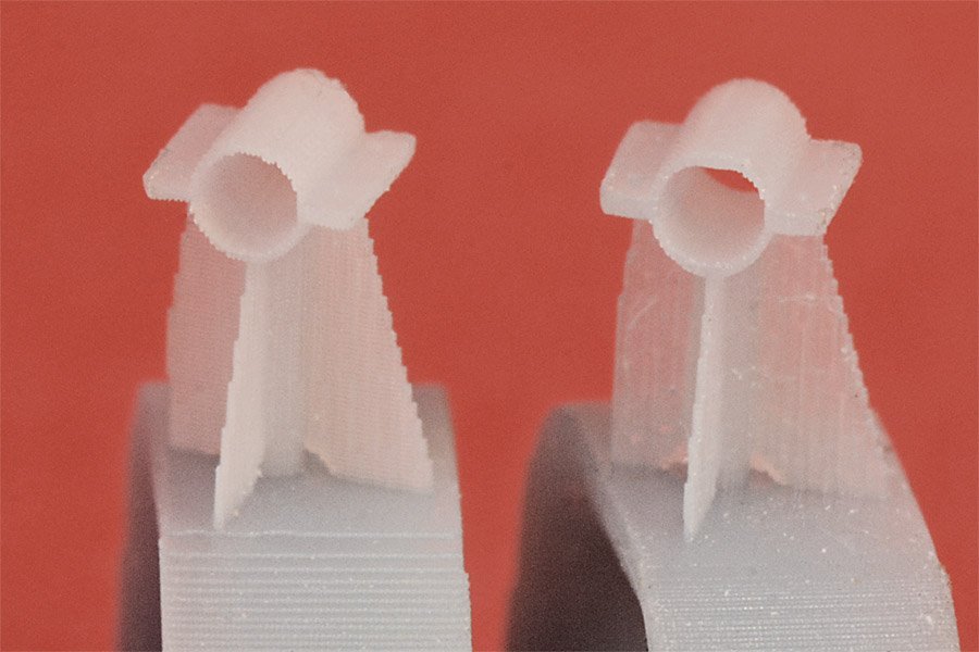
As I said earlier, I am a novice at 3D printing, having started after last Christmas when I received an Anycubic Photon Mono printer as a (totally unexpected) gift. The Admiral's youngest son gave it to me, and he readily admitted that he did it because he has one, and wanted me to figure out how to use it and be his tech support! I have been into digital photography for decades and had a pretty good idea about pixel density and image quality. But with 3D resin printing there is another dimension, the vertical step size. And there are a few complications due to this third dimension that I hadn't thought of and learned the hard way. First let's consider the basic 2D pixel size. This is what the LCD display produces, and is the fundamental limiting factor in print resolution or surface smoothness. You might think more pixels in the LCD display is better, and basically it is. But there is a catch. Larger displays tend to have more pixels, and they allow larger things to be printed. But more pixels does not automatically mean better resolution or smoother surfaces. Consider a 3" x 2" display with 100 pixels per inch (300 x 200 pixels). Each pixel is 0.01" x 0.01" (0.25 mm x 0.25 mm). Now imagine a 4" x 2.6" display with 100 pixels per inch. There are 1/3 more pixels but they are still the same size. It is the number of pixels per inch/cm that determines resolution, not display size. If you had a larger 4" x 2.6" display with the same 300 x x200 pixels, each pixels would be larger, and the resolution/surface smoothness would be less. On the Photon Mono the pixels are 0.05 mm x 0.05 mm and this determines the minimum horizontal resolution for the printer. Here is a picture showing how pixel size determines resolution: The "circle" on the left has pixels 1X the grid spacing, and the one on the left has pixels 2x the grid resolution, or an area 4 times as large as the one on the left. It is clear that the larger pixels cause larger "jaggies" than the smaller pixels. But it may not be obvious that the smoothness of vertical surfaces is limited by pixel size. If the circles are extruded (printed) vertically, the resulting cylinder on the right will have deeper grooves in the sides than the one on the left. So smaller is better, and this may be more important than the total number of pixels. Less obvious is the effect the vertical step size has on surface smoothness. Of course the smoothest surfaces are either perfectly horizontal or vertical flat surfaces. But with non horizontal or vertical surfaces things are different. The smoothest angled surface you can get is at a 45 degree angle to horizontal with the horizontal pixel width and vertical step size the same. Again, you can see the 1x pixel/steps create a "smoother" surface than the 2x and 4x pixel/step sizes, so again smaller pixels produce smoother surfaces. But not perfectly smooth because pixel size will always be finite, producing finite sized steps. So to get the smoothest angled surfaces the part should be oriented as close as possible to a 45 degree angle from horizontal. For the Photon Mono with 0.05 mm pixels the step size would be 0.05 mm. But this one to one pixel/step size smoothness rule applies only to 45 degree slopes. For shallower slopes the step size is all important for getting smooth surfaces. In this picture the red line is angled at 10 degrees from horizontal. The horizontal "pixel" size is 4x, and the vertical step size is 1x, 2x and 4x. Clearly the 1x vertical step size produces a "smoother" surface. It has more jaggies, but they are smaller. On the Photon Mono the minimum vertical step size is 0.01 mm (0.0039 inch), about the thickness of a sheet of printer paper. This isn't just a theoretical conclusion. Look at these pictures: In both images the capstan (above) and wildcat (below) were printed at 0.05 mm and 0.01 mm vertical steps. The 0.01 mm vertical step parts (right) are clearly smoother than the 0.05 mm parts (left). This is most apparent on the near horizontal surfaces. Of course, you can't get something for nothing. You have to print 5 times as many slices at 0.01 mm step size as with a 0.05 mm step size, and that takes 5X as long for the exposure process. However, as described below, this does not mean 5x as long total print times. Things aren't as simple for vertical surfaces. In these three examples the red line is angled 10 degrees from vertical and the vertical step size is the same, 1x. But you can see the surface smoothness is very different for the three examples. The vertical step size has no affect if it is smaller than the pixel dimension. The reason is simple - no matter what the vertical step size is, the horizontal "step" size is determined by the LCD pixel dimensions, and smaller pixels are better. You can print as many steps as you want (smaller or larger vertical step size) and the jaggies are still determined by which pixels are turned on or off in the LCD display. However, using vertical step sizes larger than the pixel dimensions will produce rougher surfaces. So for objects with vertical surfaces angled 45 degrees or greater from the horizontal you should use a step size equal to the pixel dimension. Again, this is not just a theoretical conclusion: Again, the chock on the left was printed with 0.05 mm vertical steps and the one on the right had 0.01 mm vertical steps. You can see the near horizontal surfaces are much smoother in the 0.01 mm print on the right, but the edges of the vertical supports are about the same roughness because the LCD pixel dimensions were the same. If you have mixed near horizontal and near vertical surfaces, use a smaller vertical step size to make the near horizontal surfaces smoother. There are a few more things to keep in mind. First is total print time. The actual exposure time for each "slice" is a fairly small part of the total print time. More time is spent raising and lowering the print stage. I have been using the recommended lift speed (4 mm/second) and retract speed (6 mm/second) for the Photon Mono. So for each slice that is printed 10 seconds expire while the stage is moving. I have used 5 second and 3 second exposure times for each slice. So the exposure time is only 1/3 to 1/4 of the total print time. Smaller step sizes do increase total print time, but not as much as you might think. Another thing to consider is the effect of exposure time on the surface smoothness of very small objects. This is tricky! The resin I have been using is the Anycubic Basic Grey. In quantity it looks opaque, but for very thin layers/slices like 0.01 mm it it translucent - some light passes through it. And this means that any resin that accumulates on top if thin horizontal surfaces may be exposed even if it isn't a part of the slice that is being printed. I have noticed that very thin horizontal cylindrical objects (0.05 mm or less) tend to print thicker in the vertical direction than in the horizontal with 5 second exposures. Reducing to 3 second exposures reduces this over thickness (the minimum recommended exposure of the Basic Gray resin for the Photon Mono is 2 seconds). A third thing to fiddle with are some "advanced" features in Chitubox. These are in the "Settings/Advanced" tab. The "Anti-aliasing Level" is an attempt to minimize the jaggies effect. It has three settings 2, 3 and 8 that cause the pixels at the edges of objects to be shades of grey instead of black or white. 2 is the grayest and 8 is just black and white. The result is that you get less exposure of the gray edge pixels than for the white interior pixels. This seems to harden less resin on these outer surfaces and it pools in the grooves, making them less noticeable. But this is a very subjective thing! The other "Advanced Tab" feature is "Grey Level." It ranges from 1 to 8, and as far as I can tell it works just like the "Anti-aliasing Level." Step 1 is the grayest and step 8 is black and white. I have been experimenting with 3 second exposure times, 0.03 mm vertical step size and an Anti-aliasing level = 2 and Grey Level = 4. There is also an "Image Blur" option, with "Image Blur Pixel" sizes of 2, 3 and 4. $ blurs the edges of the surfaces the most and 2 the least. I haven't experimented with this yet. Finally, exposure time affects the hardness of the printed slices, and that affects the success or failure of your prints. That is the subject of the next post.

-
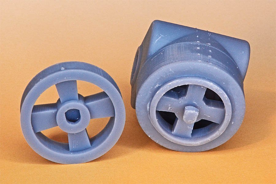
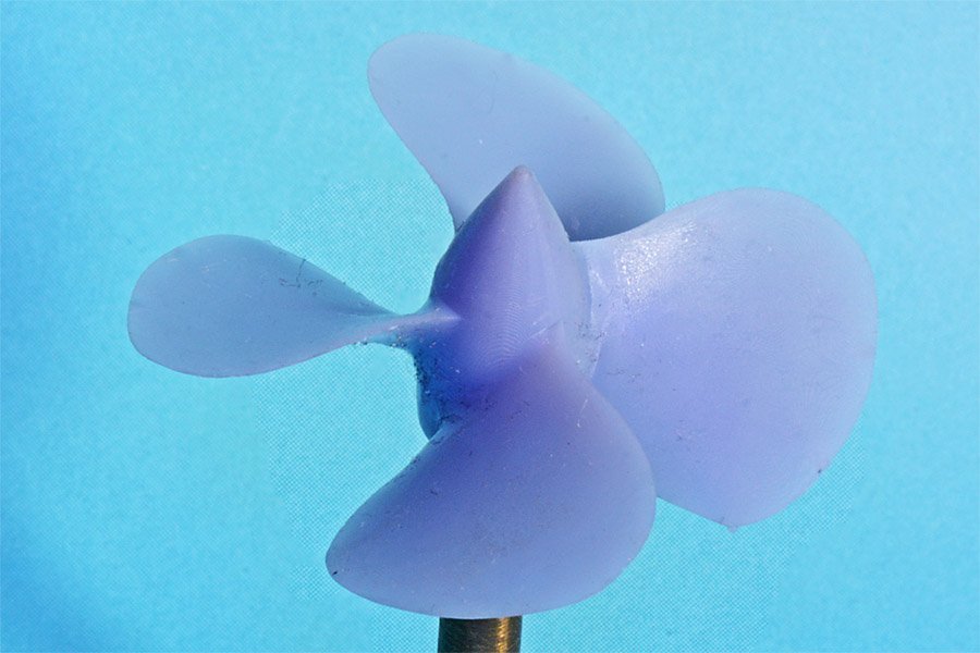
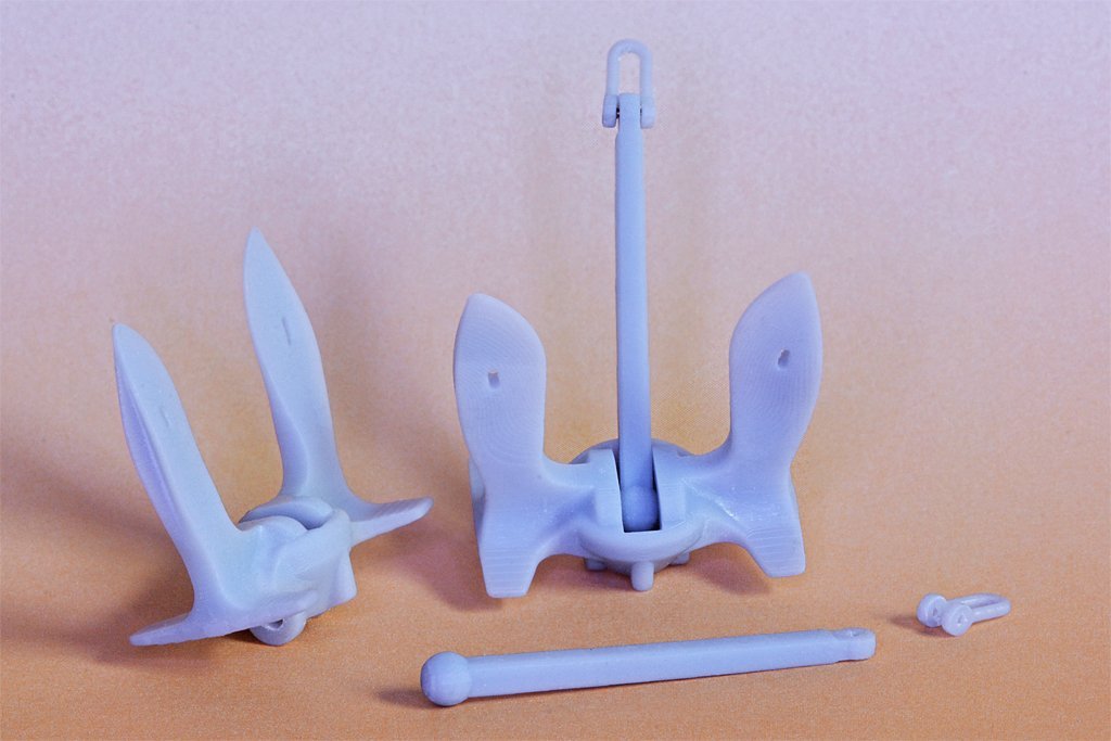
I have been working with an Anycubic Photon Mono since Christmas and thought I would pass along a few things I have learned. I have used the CAD program "DesignCAD" since 1988. It is a surface/mesh program with true 3D solid capability, but most of what I have done has been just planes and meshes (grids) that have zero thickness. I combine these to create the 3D object but they often have leaks and are unsuitable for 3D printing without some "repair." Microsoft's "3D Builder" program is free for Windows 10/11 and does (almost) perfect repairs. The only catch is that it will place a surface over any closed opening in a single plane/grid. So I have to be sure I create separate surfaces around holes. I don't know if this is a requirement for STL files that some programs do automatically. It is not a problem for solids that I have "drilled" by subtracting a tool solid, so it is just a problem with the way I made some of the objects. I use the Chitubox slicer program, and it does a pretty good job with the default settings. More about this in another post. Here is a link to a 3D model I created. I am now printing many of the parts you see on this ship. https://modelshipworld.com/topic/19321-uss-oklahoma-city-clg-5-1971-3d-cad-model/?do=findComment&comment=590228 https://www.okieboat.com/CAD model.html I started a 1:96 scale physical model about 16 years ago but stopped until I finished the CAD model. I have started the build again and am 3D printing parts for the model. https://www.okieboat.com/Ship model page.html I have been amazed at the resolution I can get with the Photon Mono printer! Here are a couple of examples of 1:96 scale parts. These are straight off the printer (after curing) without any touch-up. The CAD model was created 1:1 scale from the original blueprints, including all the proportional angles and dimensions of the real thing. At 1:96 scale the blades are only 0.25 mm (0.0095 inch) thick. This is far too thin to try to machine and much too thin to try to cast. But I just scaled the file to 1:96 and printed it! The diameter of the propeller is 1.46 inches (37 mm). They printed perfectly the first time using the default supports added by Chitubox. For this print I used a vertical step of 0.01 mm, 0r 0.0039 inches. The surfaces are smooth to the naked eye, but with 10X magnification I can detect a hint of the digital "jaggies." The anchor was also created 1:1 in CAD from Navy drawings. It is made up of dozens of individual complex curve surfaces. I figured if this would print anything would! It also came out perfect the first time! This was a 0.05 mm vertical step and some slight jaggies are visible on the bottom surfaces of the flukes. So this was the result of my first attempts to print with this printer. It just seemed too easy, especially since I already had all the CAD files prepared! But this was just beginner's luck, as I will explain in another post.
-
This was a good first wooden ship model. First builds are never perfect. It looks like you learned a lot from it and that is what first builds are for. What's next?
- 11 replies
-
- 2
-

-
- Corel
- Flying Fish
- (and 2 more)
-
John makes a good point. Ships weren't launched with masts installed. So if you make an "as launched" model you don't need the masts. Or if you wanted a small bit of rigging you could only install the lower masts, shrouds and stays.
-
I believe Valery V showed how he used the electroforming process to make ventilators for this cruiser Varyag.
-
Michael, This reminds me of something from my childhood. In the 1950s my dad occasionally stopped by a railroad yard (a very very short short line) so I could climb on the 1880s era steam locomotives that were still in use. Then the railroad retired the locos (one went to Hollywood for use in movies) and built its own locomotive with four V8 Buick car motors and a hodge-podge of sheet metal, steel I beams and other car parts. One of a kind!
-
A few years back I helped restore an old pipe organ. The control air powered switch bellows used a very thin lamb's skin (probably less than 0.5 mm thick), like was used on the original organ. I don't know where you would find this material, but someone must have an organ repair web site that will give a source.
-
I have not finished a model of the ship and it may be years before i do. I was working with Yankee Model Works on a 1:350 model of the USS Oklahoma City CLG-5 (1971 configuration) but the 2008 recession shut them down. I haven't heard anything more about it. I have seen models of the OK City offered on the Internet, mostly by someone in the Philippines, but they are junk. They are a mix of the USS Little Rock CLG-4 and the USS Providence CLG-6, and the radars, towers, communications antennas, boats, winches and several other things were just wrong! I do not know of any company that offers a model of the USS Oklahoma City in any date/configuration.
- 54 replies
-
- 1
-
-
- 3d cad
- cleveland class
- (and 1 more)
-
Small Brass or Steel Brushes for Dremel or Similar
Dr PR replied to KeithAug's topic in Modeling tools and Workshop Equipment
Kieth, I have used the Dremel brand steel wire brushes and they are pretty durable. But as you noted after extensive use the disk type brush wires do bend, reducing the diameter of the brush circle a bit. The axial brush wire also twist somewhat helical but I haven't had one "ball up." I suspect something like this will happen with any wire brushs. For removing soft (tin/lead) solder a light touch is all that is needed. I don't have much experience with the harder silver solders. -
That all depends - do you want to be finished? Are you satisfied with it as is? Some people add some of the sail rigging even if there are no sails. The vessel is rigged to be ready to accept sails. For example, the jib halliard and downhauls are rigged. The halliard is rigged through the block on the mast and the sail head end is brought down to the bowsprit . The downhaul is rigged out on the bowsprit, through the block/sheave and hooked to the end of the halliard. This way it is only necessary to bring up the jib and fasten the head to the halliard and downhaul. With the tack fastened to the bowsprit all you have to do is haul on the halliard to raise the sail. Of course the sail would also have to be laced to the jib stay in the process, and the downhaul run through several of the lace loops, but it would be faster than having to rig the lines first. In a similar way the clew lines and sheets of square sails can be rigged and hooked to each other before the sail is hauled up to the yard. Take a look at the Model Shipways kit No. 2003 "Dapper Tom" instructions (available on line) to see how they rig the sail lines without adding the sails. It adds more rigging and makes the model look a bit more complicated or complete. So it all depends upon whether or not you want to do more rigging.
- 42 replies
-
- 2
-
-
- lively of baltimore
- lumberyard
- (and 2 more)
-
Valeriy, Very nice work - as usual! I sometimes use a Dremel motor tool with a wire brush to remove excess solder from joints. It is very effective for removing excess solder.
-
Masking tape lifting
Dr PR replied to Jeff5115's topic in Painting, finishing and weathering products and techniques
There are some tricks to masking with tape. Paint adheres best to somewhat rough surfaces. Sanding with medium grit sandpaper (150-200) will usually produce a lightly scratched surface that paint will adhere to. Be sure to clean the dust and grit from the surface before painting. Primers are formulated for good adhesion, and the matching paint adheres to the primer. Some paints are "self priming" meaning that you can apply several thin coats of the same paint. "Thin" is the key word here. I have found it is best to remove the tape as soon as the paint becomes tacky, and before it can dry and harden. If it forms a tough dry film up and over the edge of the tape it will tend to lift when the tape is removed. If you are worried about paint bleeding under the tape there is a simple trick. For example, suppose you have painted the bottom of a hull red and then want to paint the top black. First, paint the bottom of the hull with red paint to above the line where you want to mask it off. After the paint is thoroughly dry (do not rush this!) apply the tape and then apply a light coat of red paint along the edge of the tape, so if there is any bleeding it will be red. After the red paint drys apply the black paint up to and over the edge of the tape. But use the paint sparingly to avoid a heavy build up at the edge of the tape. A slight raised bead of paint is common along the edge of the tape, especially if you apply a heavy coat of paint. After the paint hardens and the tape is removed it is pretty easy to eliminate the edge with very careful and gentle scraping.