Dr PR
-
Posts
2,406 -
Joined
-
Last visited
Content Type
Profiles
Forums
Gallery
Events
Everything posted by Dr PR
-
 It would be useful if you gave the resulting output file size in kilobytes or megabytes. Some web sites and email systems limit the size of files that can be sent.
 -
I have used several bitmap to vector converters, but not recently. Some of the CAD programs I have used have built-in raster to vector converters. Adobe used to have a stand-alone converter long ago but I'm not sure about the name (Streamline?). None of them have worked very well. As mentioned above, bitmap lines have non-zero thickness and vector lines are zero thickness (but they may be displayed with a variety of thicknesses). If the bitmap line is not always the same number of pixels wide - and they rarely are - the converter may have trouble guessing the line center and generate a bunch of slightly zig-zag segments instead of a single straight line. Curves become a series of short segments instead of a smooth curve. Another problem is the way the converters deal with intersecting lines. Many use algorithms that fail to see across intersections to create a continuous line. Instead, at the intersection they switch from the original line to the crossing line. So at an "X" you get two ">" and "<" lines instead of "/" and "\". The result is really bizarre convoluted lines. The result can be extremely large files with huge numbers of short line segments. I agree that it is usually better to just hand trace the drawing. However, the bitmap to vector conversions are not totally useless. You can put the converted drawing on one layer and lock the layer. Then on other layers you can trace it quickly just by snapping to points on the converted drawing. This is a LOT faster than trying to draw over the bitmap image. It isn't perfect though. You will have to go back and make some corrections, especially to get parallel lines actually parallel.
-
Epoxy paint?
Dr PR replied to Patrick Matthews's topic in Painting, finishing and weathering products and techniques
I have used a clear epoxy paint to seal the inside of model hulls. It was a paint model airplane builders used to seal balsa engine mounts to make them fuel proof. It soaks into the planks and bulkheads and make a very strong hull. One hull 35 years old has never developed cracks between the planks due to wood shrinkage - a couple of older hulls have developed cracks. And it doesn't change color as far as I can tell (not a problem inside hulls). One caution about epoxy paints. We used white epoxy paint in the missile house and nuclear weapons magazines on the USS Oklahoma City CLG-5 back in the 60s and 70s. It produced a hard surface that resisted wear better than ordinary Navy paints, even on the decks! This was important because the ship was in WESTPAC for ten straight years and couldn't offload ammunition to clear the magazines for painting. But the white paint yellowed fairly quickly. Here is a related tidbit. The gray paint the Navy provided for painting exterior surfaces wore off quickly. We had to repaint very often. I remarked that we should use gray epoxy paint because it would last longer. I was asked what we would do then to keep the sailors busy! Chip, prime, paint, chip prime, paint ... -
An armed capstan
Dr PR replied to bruce d's topic in Discussion for a Ship's Deck Furniture, Guns, boats and other Fittings
I don't recall now where I have seen it, but I remember seeing a picture/drawing showing muskets stowed around the capstan. My guess is that they were placed there before an action for ready access when boarding an enemy ship. They wouldn't normally be stowed there but would be below in the armory. I can see having a swivel gun mount on the capstan. The capstan mount was very strong and could take the force of recoil of the gun. If the ship was being boarded the capstan would give a good field of fire for sweeping the decks of boarders with grapeshot/shrapnel. The gun could also be fired at men in the tops of an enemy ship at close range. -
I have followed this topic with interest. I looked around on the Internet and found a company (GoodFellow) that sells very fine high purity wire, down to 0.01 mm, much finer than the "LCD cutting wire." And you can get it in a variety of elements and alloys, even very toxic elements like beryllium. However, a meter of 0.01 mm very pure copper wire was US$459! A source of very fine copper wire is "extremely flexible" stranded test lead wire. We used some of this in a project a while back. It comes in a variety of strands and wire sizes up to 1064 strands of 56 AWG wire ( 0.000492 inch, 0.0125 mm diameter). 10 feet (3.049 meters) for US$26.43 (Mueller Electric WI-M-10-10-0, Mouser 548-WI-M-10-10-0). That is 10 feet x 1064 strands = 10,640 feet (3243 meters). That should last a while! Virtually all metals will burn in air if they are fine enough. But wood, plastic, thread and just about anything else that is 0.02 mm diameter will also burn in air if heated hot enough. So it is pointless to worry about fine wires burning. By the time the wire is hot enough the rest of the model will be ashes.
-
The breech rope did provide the final stop for recoil. But most of the recoil energy was absorbed by the gun tackle. If you have ever used multiple block tackle to hoist an object and then let the loose end go you will have seen that the tackle slows the fall. The loose end of the gun tackle rope was laid out straight on the deck (or held by the tackle men) so it would run through the blocks without fouling. The line running through the blocks served as a shock absorber to slow the gun. The breech line then stopped it in the loading position. This is described in detail in several 19th century ordnance manuals.
-
As I understand it, the snow mast allowed the gaff sail to be raised and lowered without interference from the main course spar and rig, and any bands or other features on the main mast. In this way the sail could be operated independently of the other sails and yards, much like the gaff sail on the mizzen mast of three masted ships. The gaff boom and the sail were attached to and moved along the snow mast. On later ships the snow mast was replaced by a cable that the sail could ride on, and later still it was done away with entirely.
-
Bob, Thanks for the info. I want to emphasize one point you made. I have been painting (art) with oils since I was a kid. Artists oils take a very long time to dry properly - I suspect some of Rembrandt's paintings aren't fully dry yet! Actually, the stuff I used took about three weeks to harden so it wouldn't smudge. As you said, this is a virtue for artists because the colors can be mixed and spread easily on the canvas, and can be retouched for a week or so. Faster drying paints are far less forgiving! For modelers the long drying time is a nuisance. You can mix a fast evaporating solvent to make the paint dry faster. But like you said, this results in a duller finish - like satin or even flat. And this is the part I want to caution people about. If you are going to use oil paints and dilute them with a thinner, always use the exact same paint to thinner ratio if you are going to go back over with multiple layers or spot touch up. Different ratios of paint and thinner dry with different amounts of "dullness." Touch up spots or overlapping layers that are done with a different paint/thinner ratio will stand out like a sore thumb if viewed in the right light. I speak from experience!
-
Edge Gluing Planking
Dr PR replied to Neil10's topic in Building, Framing, Planking and plating a ships hull and deck
I don't know what the experts do, but I have a suggestion. IF you are planking on a plank on bulkhead hull, and IF you haven't installed the deck, and IF you are doing single layer planking THEN don't sweat the edge gluing. Plank the hull and then paint/coat the inside of the planking with thin epoxy - epoxy paint. It will soak into the wood of the planking and bulkheads, and between the planks. It makes a very solid hull and the planks will never open up with gaps between the planks. At least it hasn't in hulls I built over 35 years ago. After the epoxy has hardened you can finish the hull with sanding. -
Topsail schooner sail plans and rigging
Dr PR replied to Dr PR's topic in Masting, rigging and sails
Thanks for the references. I have followed your build. Your name caught my eye. I had a friend many years ago in grad school named Bob Garcia. Dr. Bob now.- 104 replies
-
- 3
-

-
- schooner rigging
- Topsail schooner
- (and 1 more)
-
Brewerpaul, You are lucky that you have the real thing to volunteer on! Where I live there are not many historical things to work on, and certainly no ships. We do have a pre-Civil War frontier fort, Fort Hoskins, that I have volunteered to help with, but that is a very slow project.
-
Topsail schooner sail plans and rigging
Dr PR replied to Dr PR's topic in Masting, rigging and sails
Seahawk, I remember reading about that method of controlling the fore course yard, presumably in Chapelle's The Baltimore Clipper. It would help control the yard as it was being raised or lowered while the ship was rolling. There has been a fair amount of discussion and speculation about the double main stays on schooners on the forum. The best came from someone experienced in sailing one of the existing ships. Right now I don't remember who or where this post is. The problem is that a stay that runs from the main top to the deck forward near the base of the fore mast, as is common on square riggers, will interfere with the swing of the fore sail (and fore sail boom if there is one) when the ship changes course. It is desirable to swing the sail out over the side to catch the wind, either running with the wind or when tacking into the wind. With a fixed main stay when the ship changed course it would be necessary to lift the fore sail and boom over the stay and that would be a slow process. It wouldn't be as much of a problem on ships that did not have a fore sail boom. The clew of the sail would have double sheets, one port and one starboard, and the sail could be pulled over the main stay with the appropriate sheet. I have also seen photos of ships with brails near the foot of the sail that could be hauled in to loosely furl the sail (no fore boom) close to the mast. These could be used to haul up the sail for lifting over a fixed main stay. One solution was to have two main stays, port and starboard. Each stay had a tackle (gun tackle or luff tackle) with the lower block hooked to a point on deck. The stay on the windward side was drawn taught to take the forces of the wind and ship's motion, while the lee side was slacked to allow freedom of motion of the fore sail (and boom). When the wind changed to the opposite side the stay on that side was drawn taught and the new leeward side stay was loosened. This was a much faster process that working around a fixed stay. Many of the drawings and plates in The Baltimore Clipper show this rig, dating back to 1800 or earlier. Several modern topsail schooners also have this rig. However, Lennarth Petersson's Rigging Period Fore-and-Aft Craft (page 80) shows a double fixed main stay anchored to bitts aft of the fore mast on the Experiment. His drawings were made (mostly) from a model of the Experiment in a Swedish museum. Another solution was to rig the main stay from the main top to the fore top. Then the fore stay took the load for both masts. In this case the fore gaff swung below the main stay. I have seen a few drawings showing this configuration. But the gaff peak halliard rigging would also have to be below the main stay and this would require the gaff to be some distance below the stay, resulting in smaller sail area.- 104 replies
-
- 6
-
-
- schooner rigging
- Topsail schooner
- (and 1 more)
-
Topsail schooner sail plans and rigging
Dr PR replied to Dr PR's topic in Masting, rigging and sails
Gregory, I'm working on it. But if you can't wait - and it may be some time before this is continued - I recommend Lennarth Petersson's Rigging Period Fore-and-Aft Craft. He includes very good drawings and deck plans showing the rigging of an American topsail schooner, including belaying points. Just about all of the sail variations I have shown have rigging similar to his example.- 104 replies
-
- 5
-
-
- schooner rigging
- Topsail schooner
- (and 1 more)
-
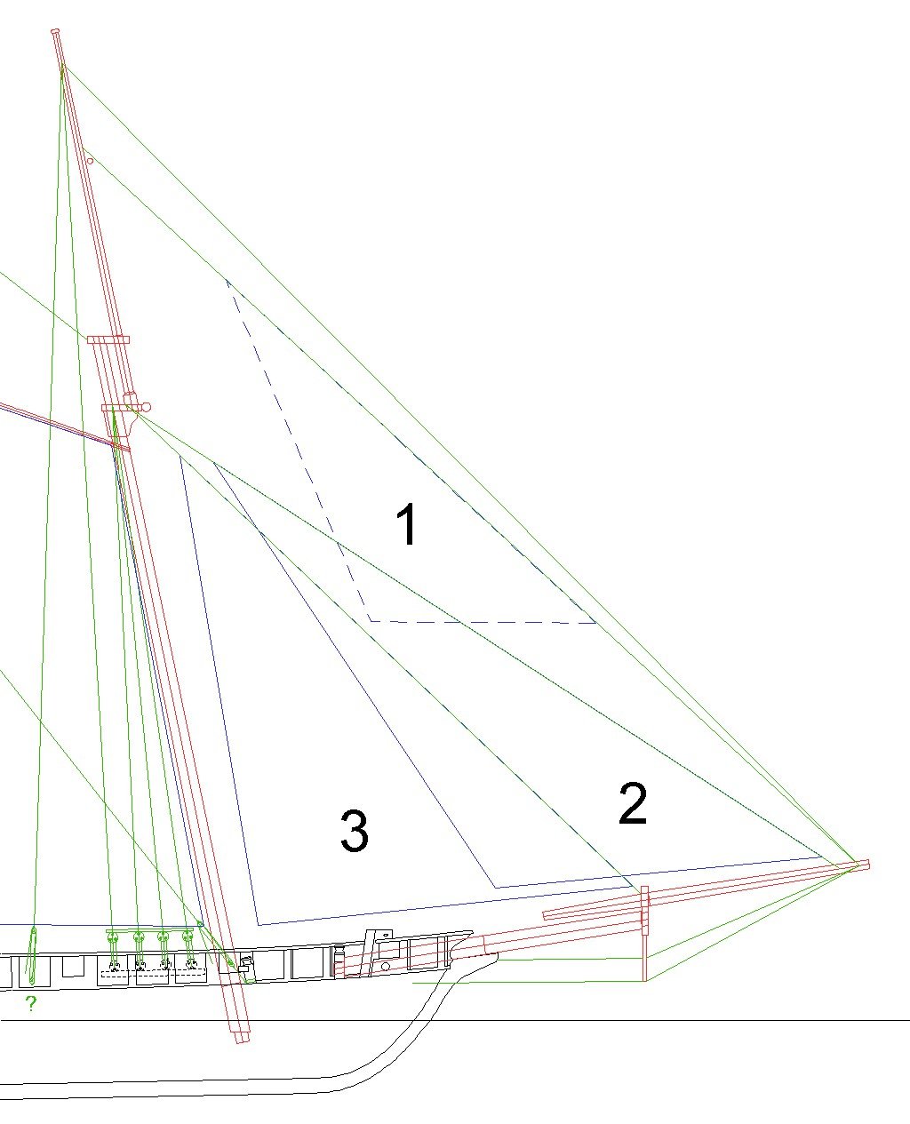
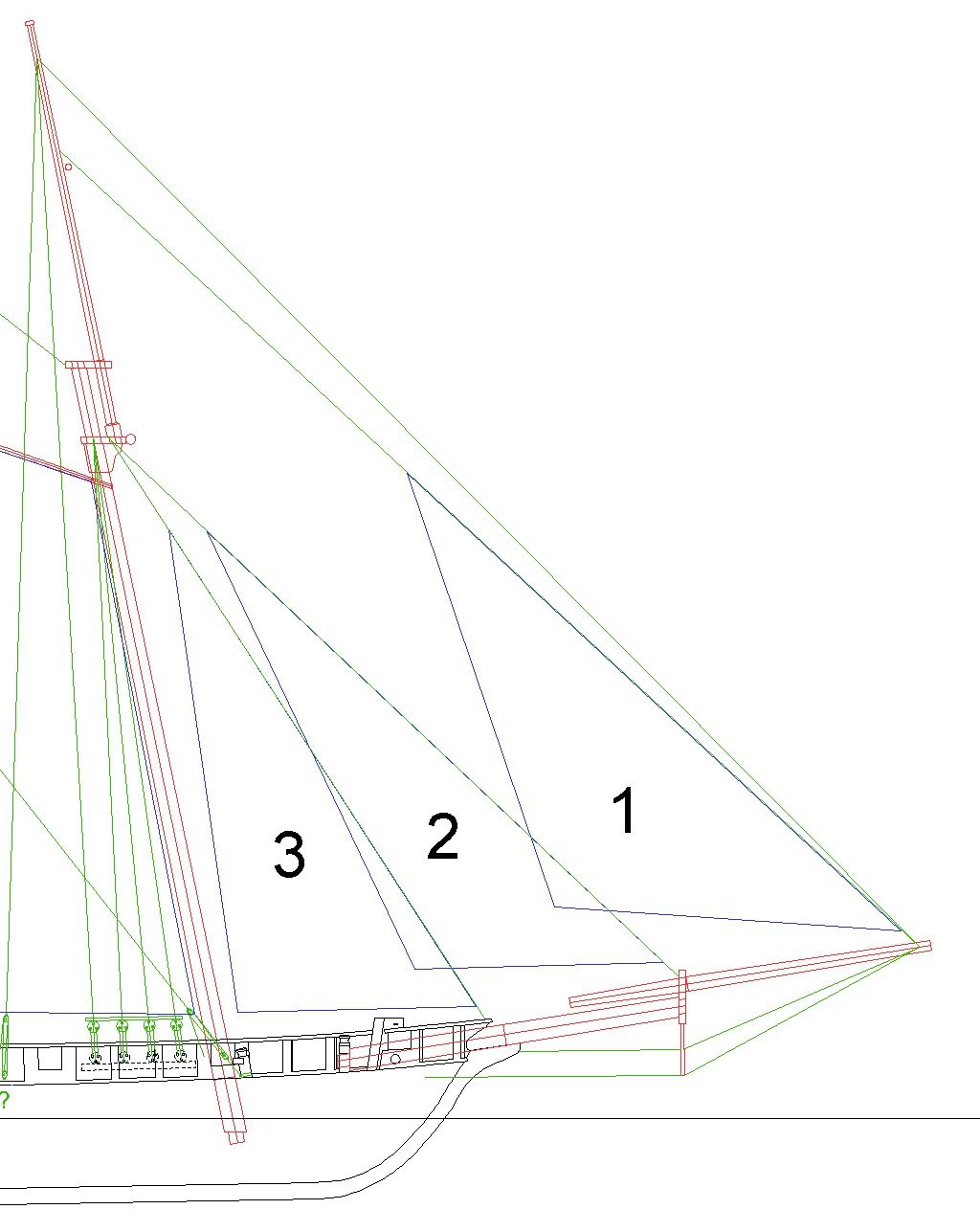
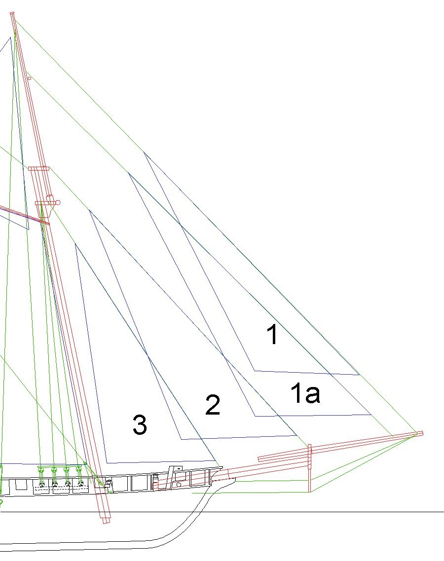
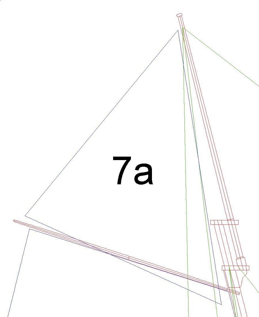
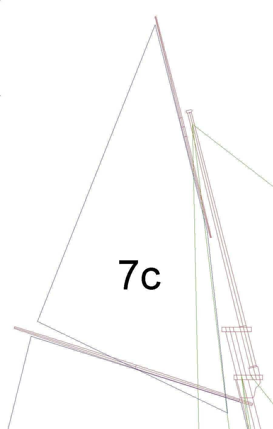
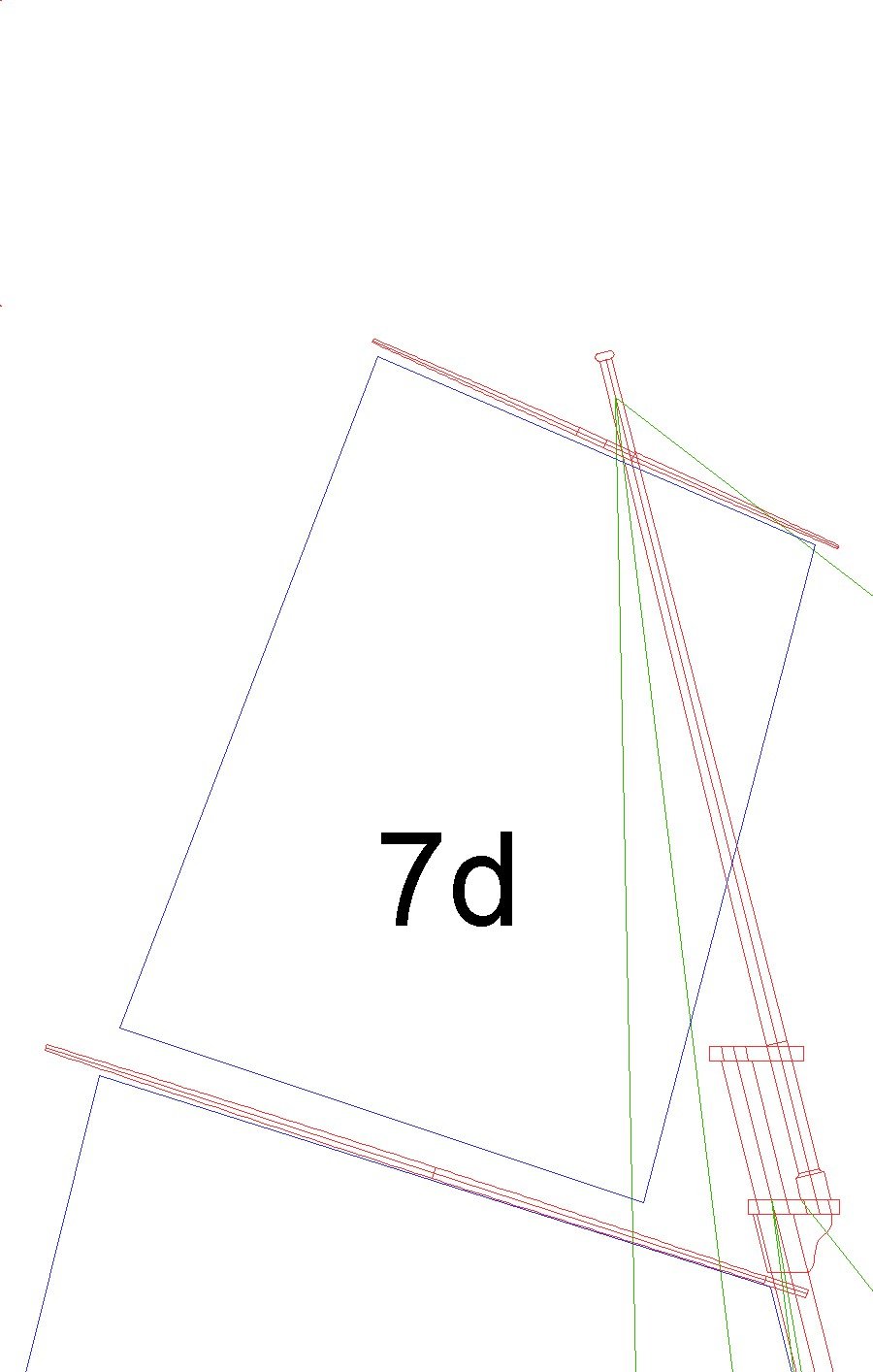
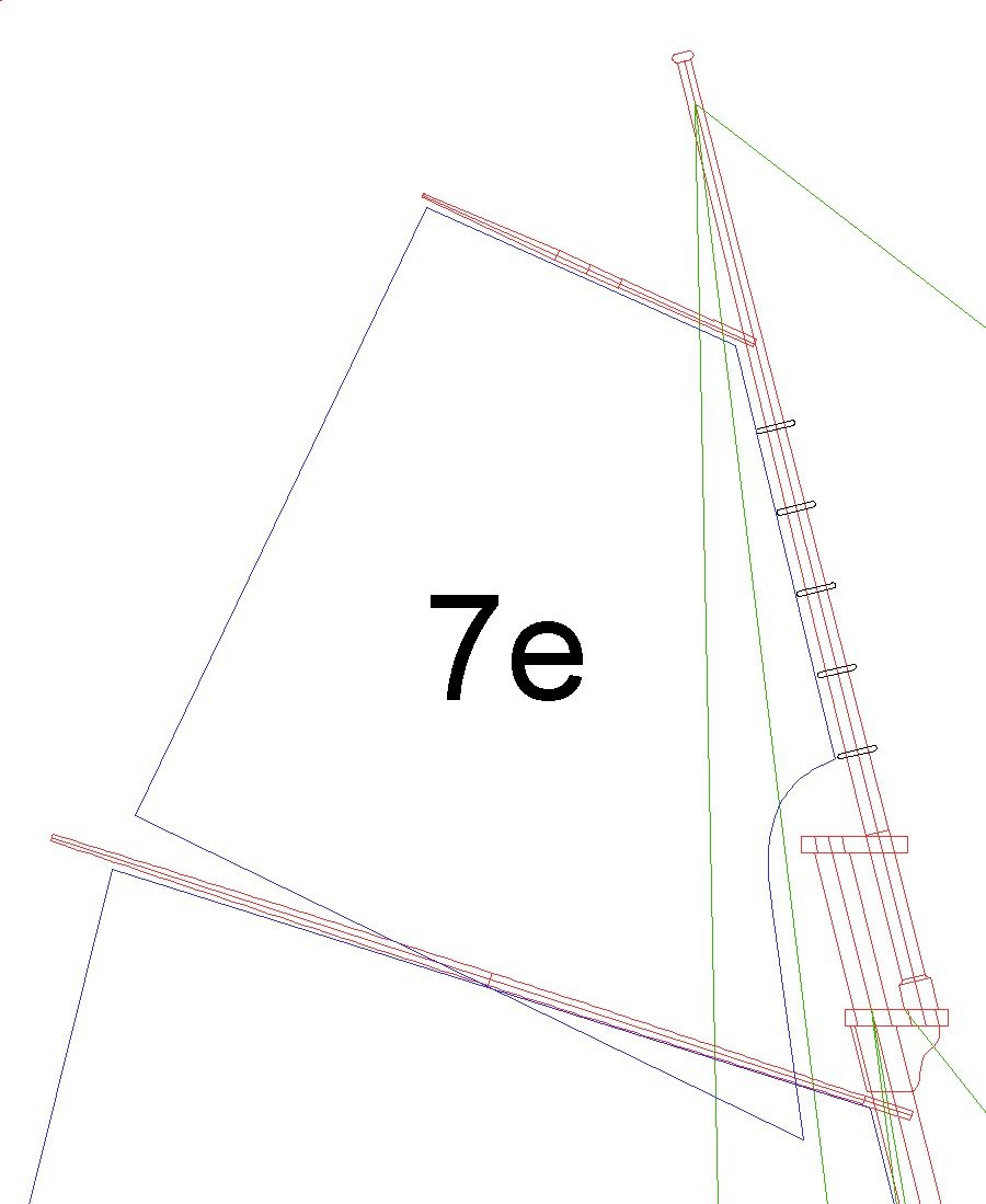
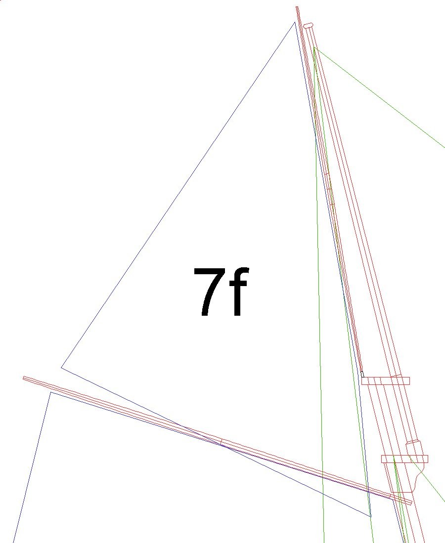
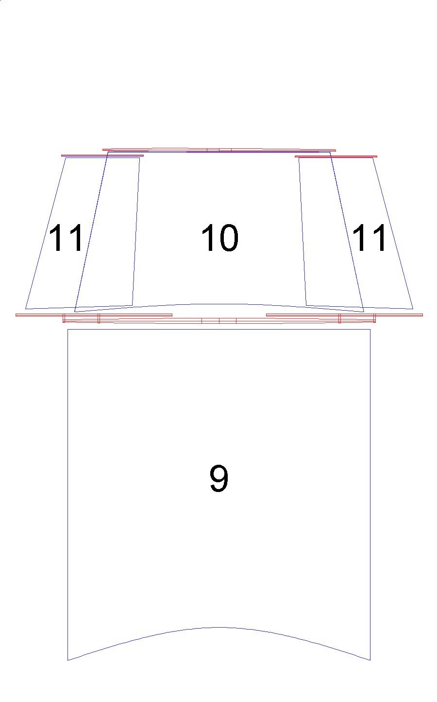
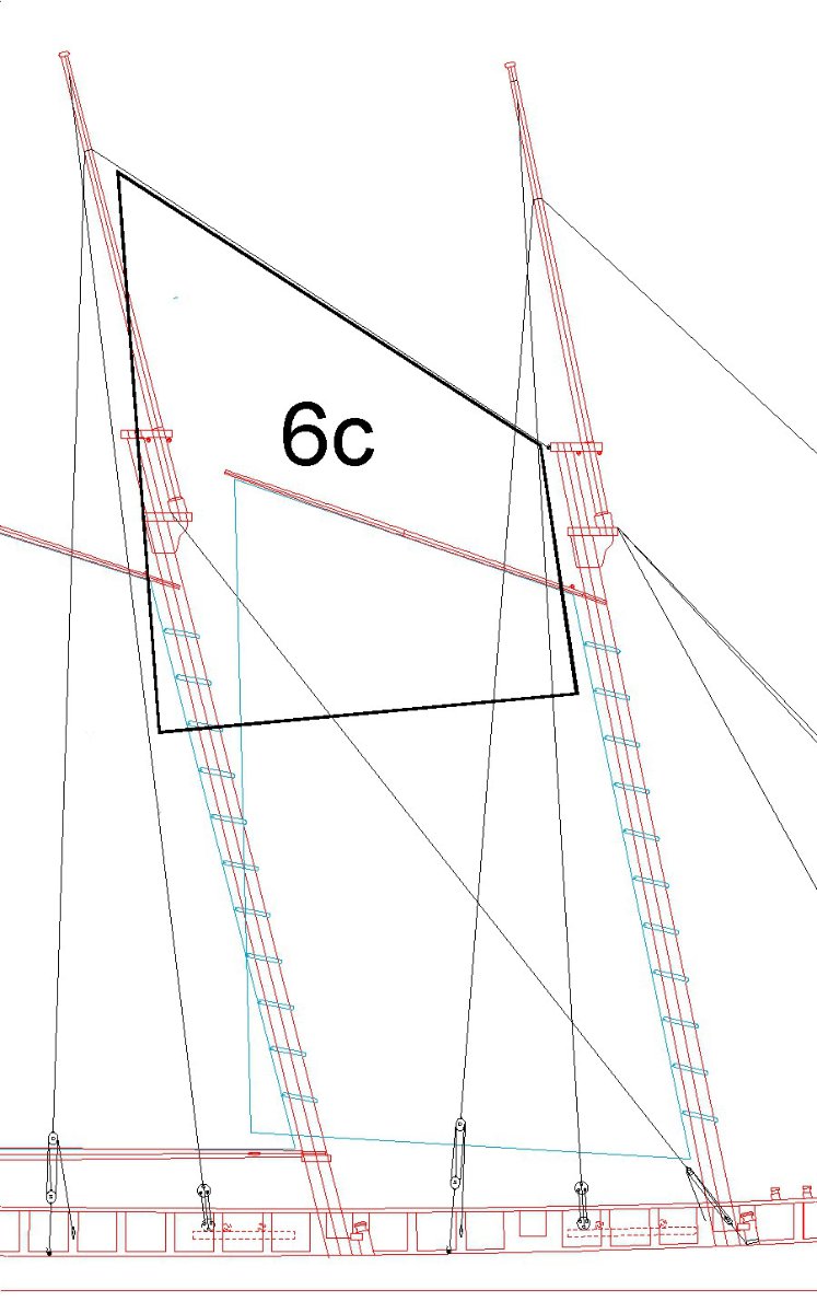
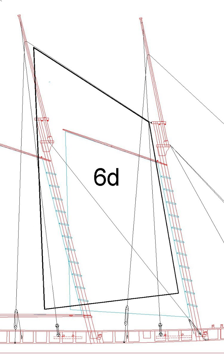
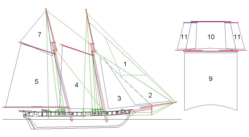
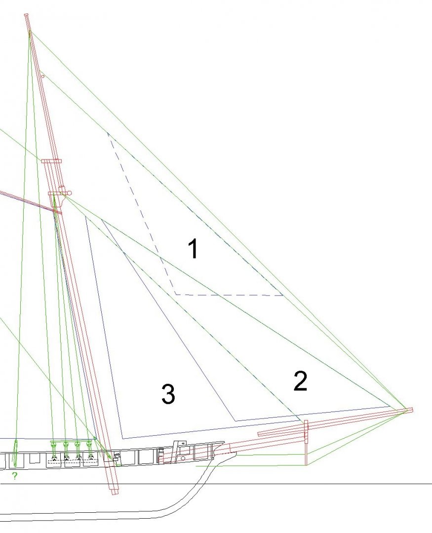
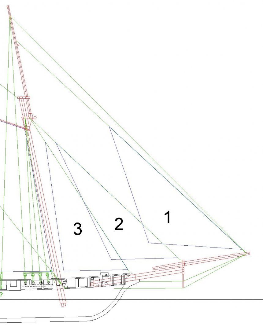
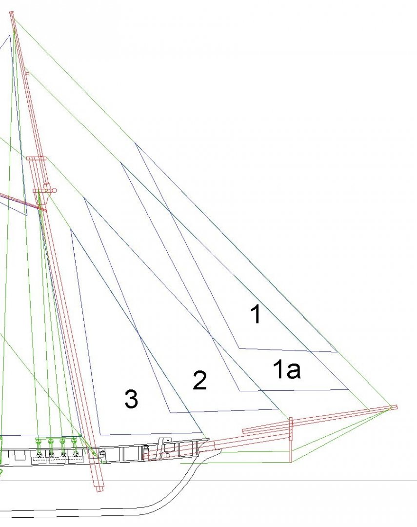
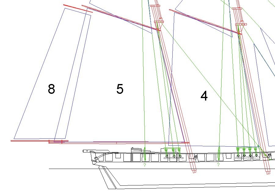
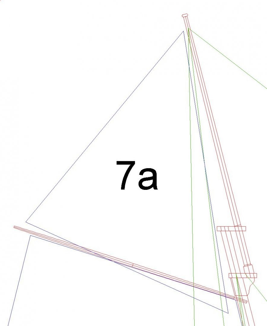
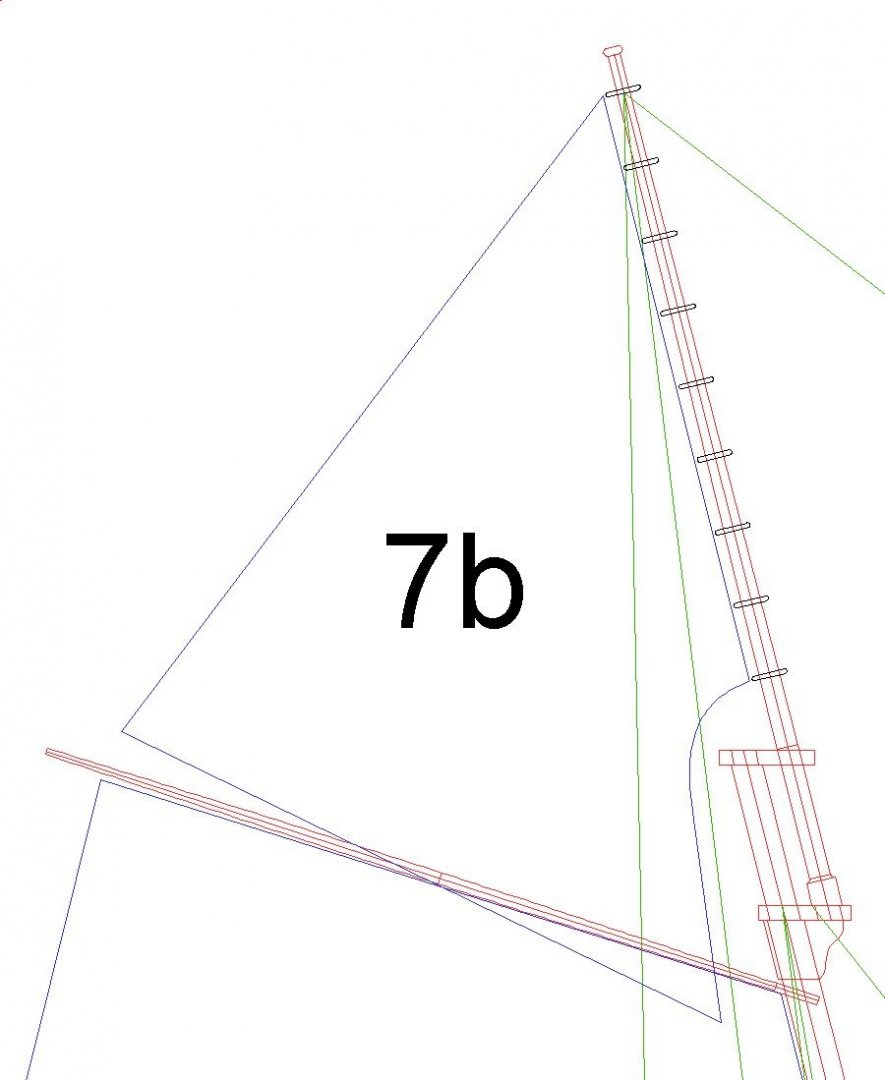
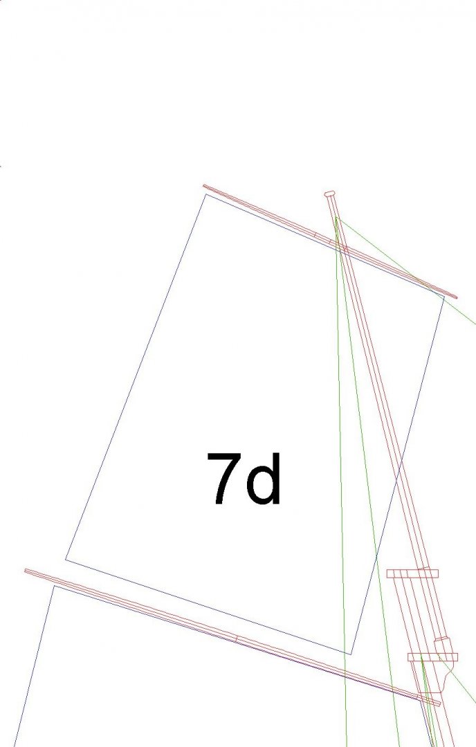
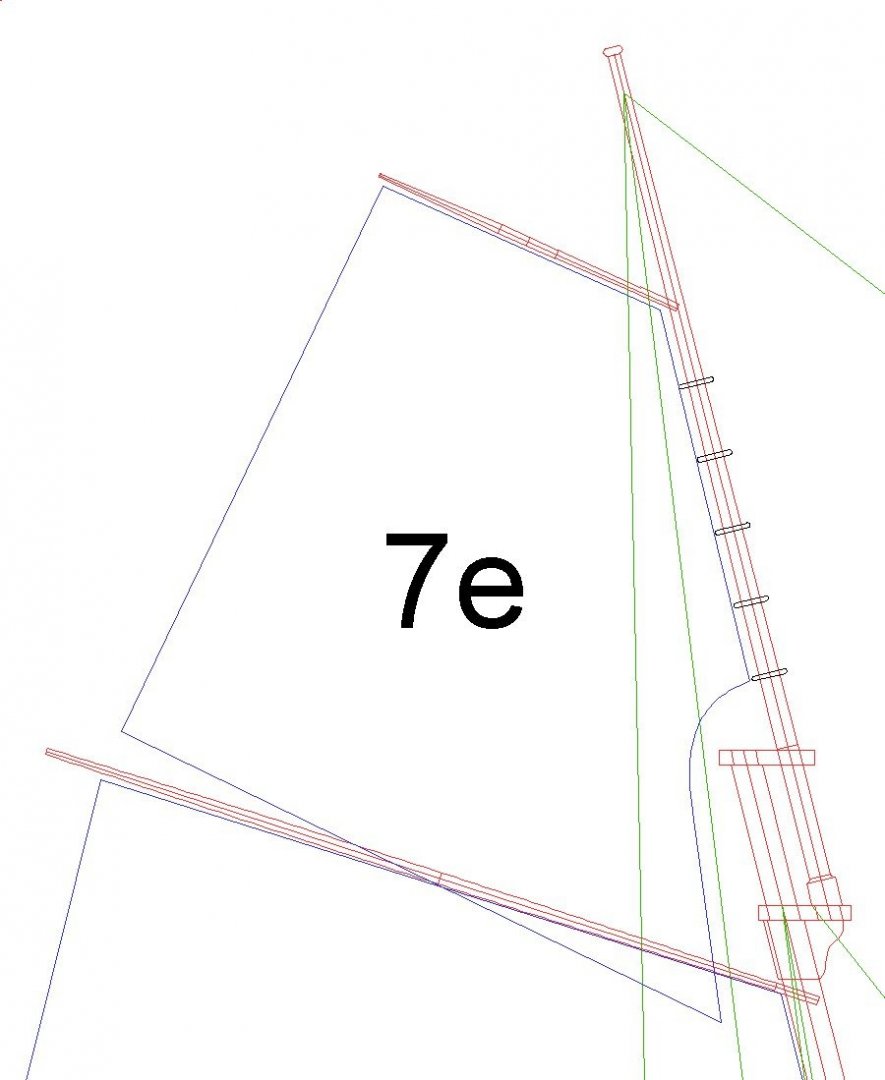
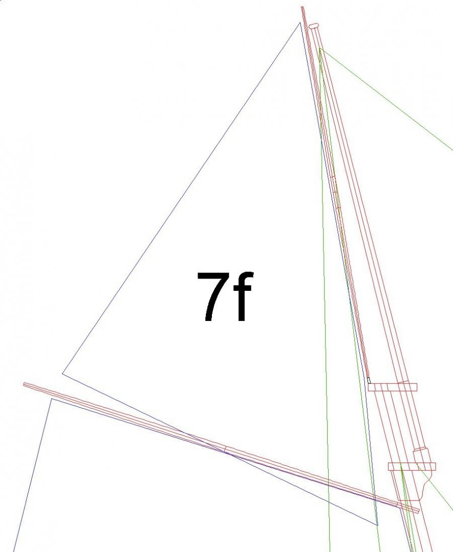
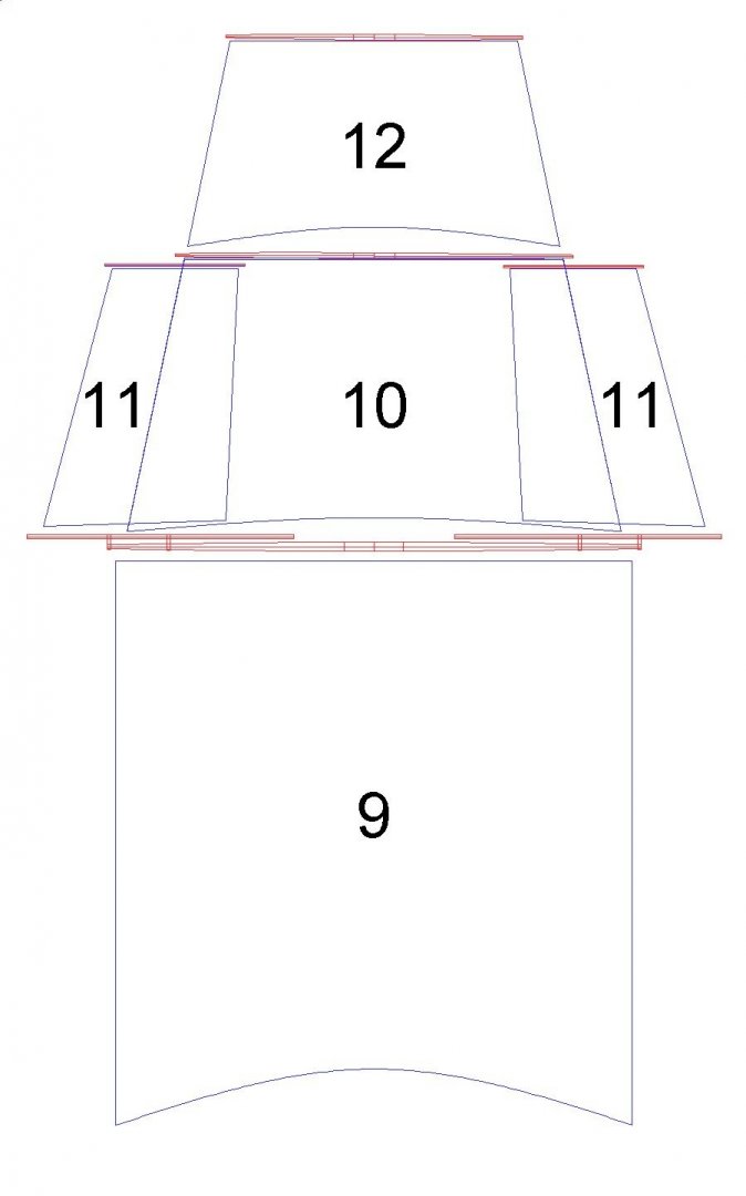
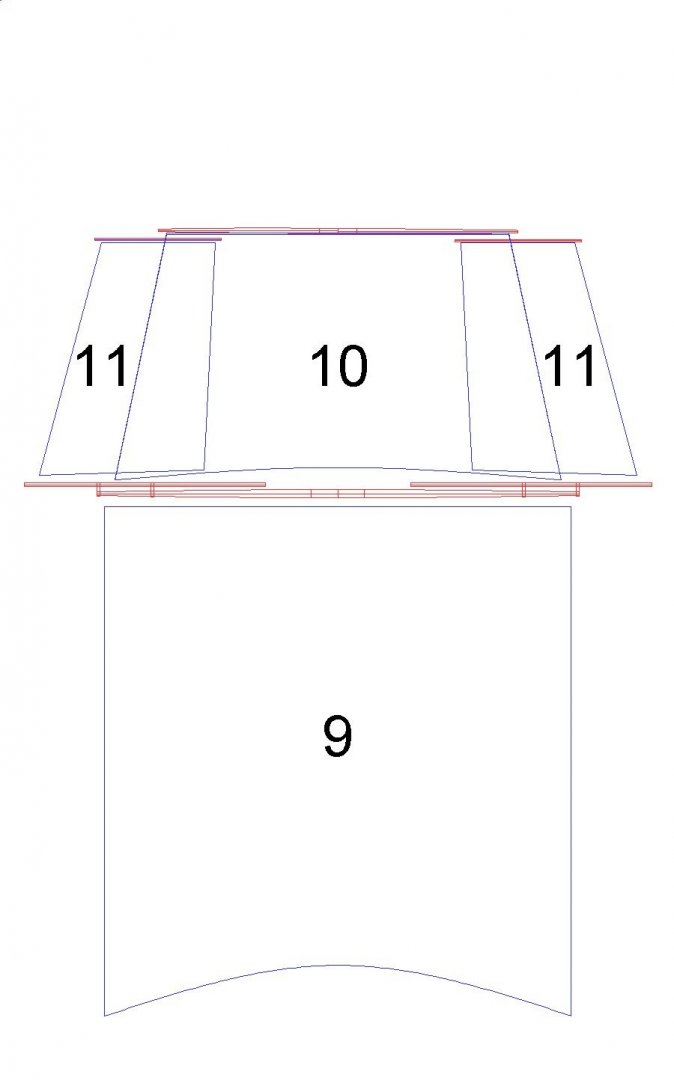
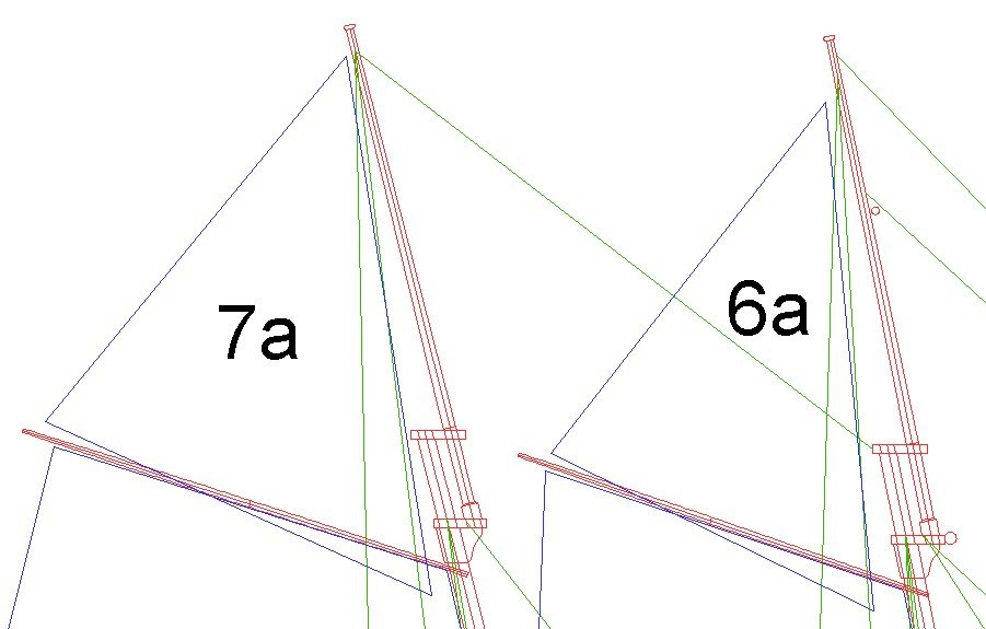
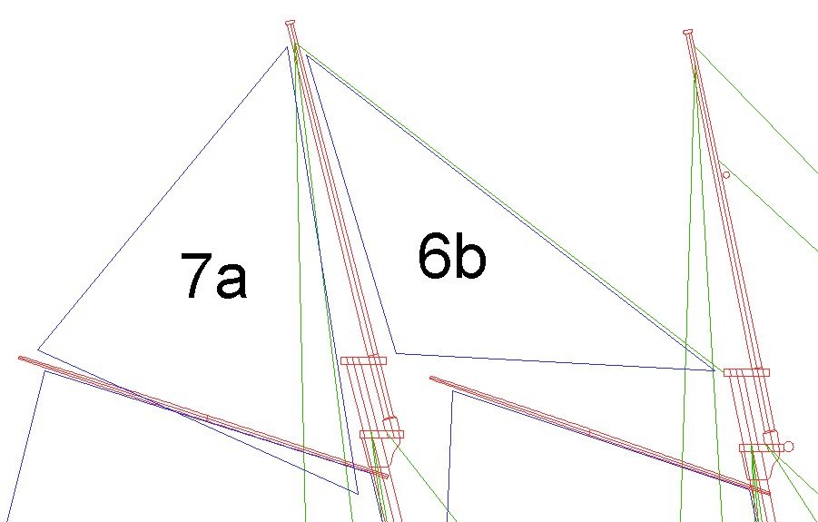
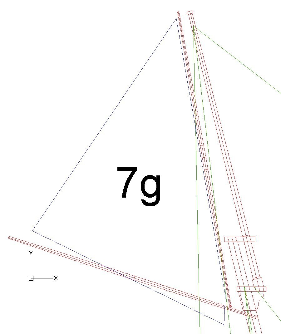
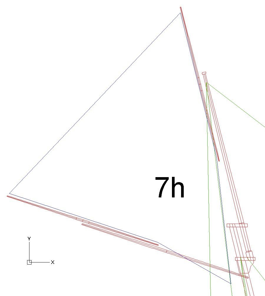
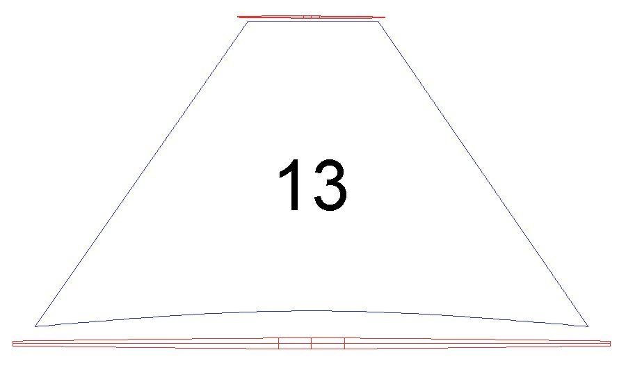
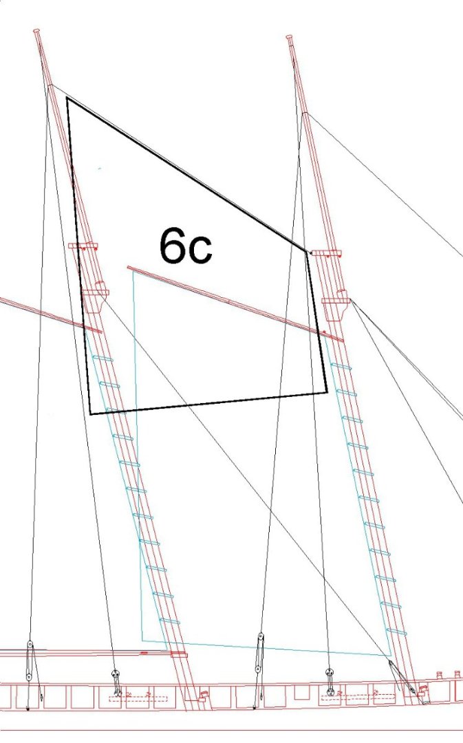
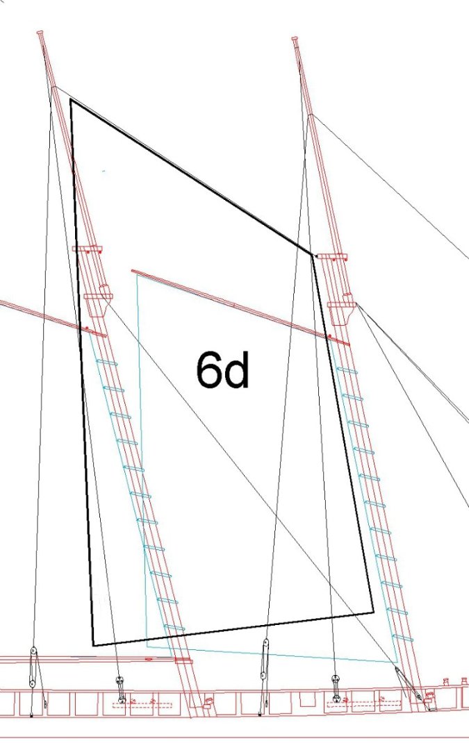
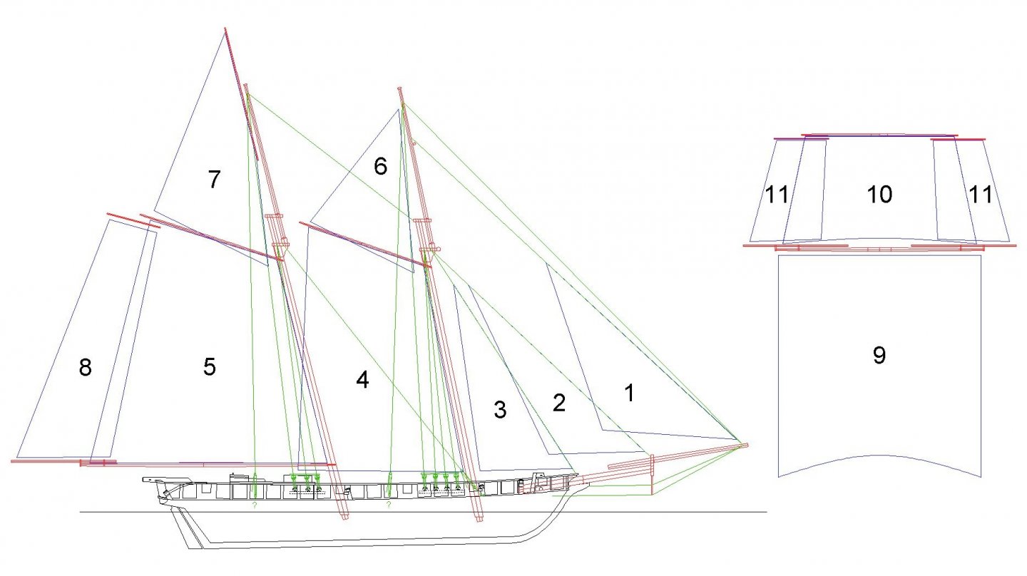
I have been researching topsail schooner rigging and sail plans. I found many questions, answers and comments on the Forum, but no one place that discussed the many variations. I decided to post information that I have found to help others who are interested in these ships. This is a sail plan for a "typical" two mast topsail schooner with one topsail on the fore mast and no topsails on the main mast. Schooners with three or more masts normally repeated the sails and rigging shown here on the main mast. The sails are: 1. Flying jib 2. Jib 3. Fore staysail 4. Fore gaff sail or fore sail 5. Main gaff sail or main sail 7. Main gaff topsail 9. Fore course 10. Fore topsail 11. Fore topsail studding sails There were many different rigs for the fore sheets. Here are a few examples. Keep in mind that the sizes of the sails and the attachment points for the stays varied quite a bit from ship to ship. These are just general guides. The position of the fore mast and distance to the bow influenced how the fore stay was rigged, and therefore the fore staysail. Some vessels had the foremast far forward, just aft of the foot of the bowsprit and knights heads. Rigging the forestay to the forward end of the bowsprit (A) was more effective (stronger) and allowed a larger fore staysail than rigging it to the deck at the bow (B). But if the fore mast was positioned farther aft from the bow, as was common, configurations B and C provided adequate strength for the forestay and allowed a suitable sized staysail. Another variation seen on some schooners is a boom for the fore staysail that is anchored to a post on the deck at the bow or on the bowsprit and controlled with sheets similar to the main sail boom. A. This arrangement was common on smaller ships, but some fairly large topsail schooners also used it. The fore staysail (3) is large and rides on the forestay attached at or near the bowsprit cap and to the lower fore top. The jib (2) is also fairly large and rides on the jib stay attached near the end of the bowsprit and to the lower fore top. These sails and stays do not interfere with the fore topsail. The flying jib (1) is shown dotted because not all ships carried one. It rode on a stay attached at the end of the bowsprit and above the working position of the fore topsail yard. If it was present it could be larger than shown here and rigged lower on the stay. There was a lot of variation in the flying jibs. B. Here the fore staysail (3) is smaller, and rides on the forestay attached to the hull near the bow of the ship and to the lower fore top. The jib (2) is smaller than in the first example and rides on the jib stay attached to the bowsprit cap and to the lower fore top. The flying jib (1) is fairly large. It may ride on a separate flying jib stay attached to the end of the bowsprit and above the normal working position of the fore topsail yard, or it may ride on the fore topmast stay that attaches at the end of the bowsprit and near the top of the fore topmast. C. This rig was found on larger schooners that often had a topsail and topgallant. The fore staysail (3) rode on the fore stay attached to the hull at the bow and the bottom of the fore top. The jib (2) rode on the jib stay that was attached near the bowsprit cap and to the upper foretop. However, this arrangement would not have been used on a topsail schooner - the stay would interfere with the topsail. The stay would have been rigged to the lower top. The outer jib or fore topmast staysail (1a) rode on the fore topmast stay that attached near the end of the bowsprit and near the top of the fore topmast above the working position of the topsail yard or topgallant yard. The flying jib (1) rode on a stay attached at the end of the bowsprit and near the top of the fore topmast. Larger ships also carried a flying jib boom (not shown) attached to the jib boom that extended farther forward, and the flying jib stay was rigged to the end of the flying jib boom. Up to five jibs (main jib, second jib, third jib, storm jib and spitfire jib) could be rigged forward of the fore staysail (but not all at once) , even on small ships like a single mast cutter! These ships were called topsail schooners because unlike pure fore-and-aft schooners they carried spars and square sails on their topmasts. The arrangement of square sails on the foremast were also found on the main mast of some topsail schooners, raising the question of whether they were actually brigs or brigantines. Smaller ships carried just the fore topsail (10) on the fore mast. They may also have used studding sails (11) to increase sail area for speed. Larger ships may have carried a fore topgallant (12) above the topsail. Up through the early 1800s the topsail was typically taller than the topgallant. In the mid to late 1800s some ships carried lower (10) and upper (12) topsails that were about the same height. Both arrangements can still be found on modern topsail schooners. Studding sails may also have been carried for the topgallants. A variation of the topsail was the raffee topsail (13) that was used on some vessels. Still another variation on this sail did away with the top spar and just flew a triangular sail. The topsail and topgallant yards were not attached to the masts with trusses, slings or parrals, but were supported entirely by halliards and in some cases by lifts. The course yards often were also not attached to the mast. This allowed the yards and attached sails and rigging to be lowered to the deck and raised again without requiring crew to go aloft. While this may sound strange this practice was also used on large square rigged ships for topgallants and royals. The sails could be rigged to the yards on deck, complete with halliards, lifts and braces, and then hauled aloft. It was a quick way to set sail or reduce canvas as needed. A consequence of this is that some schooners did not have rat lines on the shrouds. When necessary to go aloft the crew climbed the hoops for the gaff sails or were hoisted aloft in a sling or bosuns chair. The courses (9) were not always flown. They were effective when sailing with a following breeze (wind from astern). It seems to me that if a ship was flying both fore course and main course it would be a brig. The course could be rigged to the yard and used like the fore sail on square riggers. In this case the yard was called the "fore course yard." However, some vessels did not carry a course and the yard was called a "spreader." On some schooners the course was not laced to the yard, but was hauled up by lines attached to the head of the sail. In some cases there was a short spar or club yard about one third the width of the head of the sail attached to the center of the sail, and this spar was raised with a halliard. In some cases a "bonnet" was attached to the lower edge of the sail. This was a rectangular sheet that increased the sail area of the course. On very large ships an additional rectangular sheet called a "drabbler" was attached to the lower edge of the bonnet to increase sail area further. However, I have seen no reference of a drabbler being used on schooners, and I'm not sure bonnets were often used on schooners. There was a consequence to adding square sails to the schooners. Pure fore-and-aft schooners have rather slender light-weight masts because there isn't much weight high on the masts and the force of the wind was distributed on the lower masts. When the topsails were added the masts had to be more robust to carry the added weight of the sails, spars and rigging. The standing rigging had to be heavier to take the added force from the square sails. Ships with square sails on the fore mast only often had fore masts of significantly larger diameter than the main masts. Another consequence, quite pronounced in the Baltimore clippers, is that the beam was widest forward at the foremast instead of midships as in other vessels. The amount of load a hull can carry is related to the amount of water displaced, so the wider beam forward produced more lift for the heavier mast. On ships with topsails on both masts the masts were the same diameter and the beam was widest midships between the masts. The largest sails were the fore and main gaff sails, also known as the fore sail (4) and main sail (5). These were suspended from gaffs or booms that attached with jaws to the lower masts just below the tops. The gaffs typically were angled upward to increase the sail area. The gaffs could be lowered to reef the sails. The sails were laced (bent) to the gaffs and attached to the lower masts with rope loops or wooden hoops. The main sail (5) was always bent to the main boom, a horizontal spar that attached with jaws to the lower mast at the lowest position that allowed the boom to swing free from side to side without striking objects on deck, railings or bulwarks. Some schooners had a triangular main sail with the peak hauled up with a halliard. This was called a "Bermuda rig." The fore sail (4) sometimes was attached to a boom - this was common on fore-and-aft rigged schooners. But many topsail schooners had "loose footed" fore sails that did not carry a boom (as shown above), and the clew (lower aft corner) was rigged with port and starboard sheets to positions on the deck or bulwark aft of the main mast. This allowed the sail area to be larger than if a boom was used. When the sail was shifted from side to side the windward sheet was loosened and the lee sheet was tightened to draw the sail around the main mast to the leeward side. A "ringtail" (8) was sometimes hoisted to the aft edge of the mainsail to increase sail area in the same way studding sails were attached to the spars. The ringtail boom attached to the main boom with hardware that allowed it to be pulled in when not in use or run out to carry the ringtail. The ringtail yard was hoisted to the end of the main gaff, raising the ringtail sail with it. It was possible to attach a bonnet (rectangular sail to the bottom edge of the sail or boom to increase sail area. The lower corners were controlled with sheets. I do not know if bonnets were actually used on the gaff sails. Another method was to attach a triangular "watersail" to the lower edge of the sail or boom, with a single sheet controlling the loose corner. Yet another version of the watersail was rigged like a horizontal studding sail, with the yard attached to the aft end of the boom and hanging vertically. The sail was bent to the yard and the loose corners were controlled with sheets. I have seen pictures of watersails used on schooners but I do not know when these came into use, or if it was very common. Some schooners carried a fore gaff topsail (6a), also called a jib-headed topsail, behind the fore topmast (this sail was also rigged as in 7c below). The top corner attached to a halyard near the top of the mast. The clew (lower aft corner) attached to a sheet at the end of the fore gaff. The throat (fore lower corner) was pulled down with a tack line. It has the advantage that it swings outboard with the fore gaff sail when the ship is running with the wind and increases sail area. The main top stay interferes with it, so it would be raised after the ship set a course. I have seen a few sail plans showing the fore gaff topsail on 19th century vessels, but it is not common on modern ships. Other ships carried a main top staysail (6b) that rode on the main top stay. A halliard raised the upper aft corner, a tack pulled the lower fore corner to the fore mast, and a sheet pulled the lower aft corner to the main top. This is a much simpler rig and is the most common configuration on topsail schooners from the 18th century to modern times. However American New England fishing schooners often carried a larger version of the main top staysail, often called a fisherman's staysail. These were four-sided sails with the peak pulled to the top of the main mast by a halliard, the throat was fastened to the fore top, the tack was pulled down to deck near the fore mast, and the clew was pulled down and often secured to the main boom. The most common form was as shown in 6c with the sail extending about half way down the fore mast. A more extreme version (6d) found on some racing vessels had the tack and clew extending almost to the deck. These sails had to be hauled down when tacking or jibing and raised again after the new heading was set. The main mast also carried a gaff topsail (7), but there were many different types of gaff topsails. The simplest version (7a), a jib-headed topsail, was the same as the fore gaff topsail (6a) described above. It was a "flying" sail with no attachments directly to the gaff or main topmast. It could be raised and lowered from the deck. The second type (7b) was the standing gaff topsail, also called a "shoulder-of-mutton" type. It attached to the topmast with lacing or hoops. It used the same halliards, sheets and tack as the flying sail to control it, but it had to be reefed by crewmen in the top. But on some vessels a brail was rigged to the corners of the sail allowing the sail to be pulled together into a "wad" to reef it by pulling on the brail from the deck. The yard topsail (7c) had the sail laced (bent) to a yard or spar that was hoisted to the top of the topmast with a halliard. The lower corners were controlled with sheet and tack like the flying gaff topsail. The American version (left above) had the halliard attached below the midpoint of the yard. This raised the upper part of the sail above the top of the topmast to catch higher breezes. The lower fore corner had to be pulled down hard with the tack to keep the spar upright. The sail was approximately triangular. This rig was very common on Baltimore clippers. The European version (7d), called a "lugsail" type, allowed the spar to hang more or less horizontally, like a studding sail or ringtail spar. The sail was trapezoidal or rectangular. Both versions 7c and 7d could be raised and lowered from the deck. A fifth version (7e) is similar to the shoulder-of-mutton (7b) except the top of the sail is bent to a small gaff that rides on the mast with jaws. The forward edge of the sail is attached to the mast with hoops. The lower corners are rigged like the shoulder-of-mutton sail. The final version (7f) is similar to the American version (7c), but the lower end of the spar was attached directly to the fore top cap. The sail was laced to the spar. A halliard was attached above the center of the spar to raise it erect. With arrangements 7e and 7f the sail could not be lowered to the deck so crewmen had to go into the top to furl the sail. Version 7f was uncommon, and may have been used only in 20th century racing boats. I have seen no evidence it was used on 18th or 19th century topsail schooners. I included it just to emphasize the variety in the configuration of gaff topsails. The Cornish yard topsail type 7g was similar to 7f except the spar was attached to the gaff boom. In some cases the bottom of the spar was attached with a metal fitting on the boom, and in other cases the bottom of the spar was tied to the boom. The jackyard topsail (7h) was introduced in the late 1800s to cheat on racing rules that limited gaff topsail sizes in some classes of racing boats. The rules were vague as to where the sheet attached, and adding the jackyard (which wasn't mentioned in the rules) allowed the sail size to be enlarged. In some cases the jackyard topsail was about equal in area to the main sail! **** Remember that these examples do not cover all possible variations in the rigging of topsail schooners, but they do show the more common rigs. If you are building a model of one of these ships, and you are having trouble interpreting the plans (or if you don't have plans), maybe these drawings will help.

- 104 replies
-
- 20
-
-

-

-
- schooner rigging
- Topsail schooner
- (and 1 more)
-
rule of thumb for braces, halyards, and clew lines
Dr PR replied to Christopher V's topic in Masting, rigging and sails
Christopher, Lennarth Petersson's Rigging Period Fore-and-Aft Craft (Naval Institute Press, Annapolis, Maryland, 2007, 121 pages) is an excellent reference for topsail schooners. It has many drawings showing the masts, spars, sails, standing rigging and running rigging, including deck plans for where all of the lines are fastened. I highly recommend this book! The first part describes rigging for British Naval Cutter (pages 10 - 65). The second part (pages 66 - 111) is for the American Schooner. The drawings and plans are excellent. There were a lot of variations in topsail schooner rigs, but most were very close to what is depicted in the book, with minor differences.- 1 reply
-
- 3
-
-
I have been doing more research into sail plans for topsail schooners. Right now this is what I am planning to rig on my model. The sails are: 1. Flying jib 2. Jib 3. Fore stay sail 4. Fore sail or gore gaff sail 5. Main sail or main gaff sail 6. Fore gaff topsail 7. Main gaff topsail 8. Ringtail or driver 9. Fore course 10. Fore top sail 11. Fore top studding sails The fore course, fore gaff topsail, main gaff topsail, ringtail and studding sails were not always raised, but were added to take advantage of winds and to put on speed. There were a lot of variations in topsail schooner rigs. I have created another thread to discuss the other rigs: Topsail schooner sail plans
-
Brewerpaul, I have a PhD in Microbiology. When I was a kid an aunt called me "Phil" when I was nice, "PR" when I was a bit naughty, and "Pill" when I was a real terror. When I got my PhD I became "Dr. PR." Some of my friends call me "Dr. Phil" but apparently that name is already in use. The sterns of these ships has been a bit confusing. Texts talk about "square tuck" and "round tuck," but like so many functionally illiterate writers they seen to think everyone understands what they mean and give no clear illustration or description of what they are talking about. Then there is the very different stern treatment that was common in the late 1800s and early 1900s, more like what I have done on my model, where the hull planking extends to the transom all around. And the later yachts and fishing schooners had yet another "modern" design with no actual transom.
-
Alan, There are other videos of the firing of this gun. In the video posted above you can see a vertical piece to the right of the hull siding. In other videos from a different angle this part was a flat sheet parallel to the hull siding. The splinters from the shot ripped the sheet to pieces, showing the effect of the splinters on anything inside the ship. The cannon ball was unlikely to strike a crewman because it was relatively small, but the spray of splinters was much larger and caused the most damage to the crew. One thing to consider - and was briefly mentioned - is that whether or not the gun was fixed or recoiled on wheels, the energy of the recoil was transferred to the ship in both cases. It was transferred directly from the gun to the hull when the gun was solidly attached to the hull. When the gun was on wheels and recoiled the force of the recoil was transferred to the ship through the breeching. But much of the recoiling gun's momentum was lost through friction (heat) so the momentum transferred to the ship was smaller. You can see this in the video - the gun had slowed considerably before it was stopped by the breeching. In later ships the gun tackle absorbed much of the recoil energy.
-
AIRBRUSH OPINIONS PLEASE...
Dr PR replied to MadDogMcQ's topic in Painting, finishing and weathering products and techniques
I have a Paasch double action airbrush and it has worked very nicely. I really like the double action - you can control the air volume and paint flow separately. This allows me to cut off the paint flow and still use the air flow to spread any runs that develop and to dry the paint. With single action brushes the air flow controls the amount of paint. I have a small diaphragm type compressor and it works fine.- 40 replies
-
- 4
-
-
- best airbrush
- compressor
- (and 1 more)
-
At sea the last thing you want is loose ropes. Those pretty coils would slide all over the place as a ship rolls and soon would be a useless tangled mess and tripping hazard. Coiled ropes were used only for showing the ship in port, and not for everyday use. Also, I never heard the word "flake" used with lines. Lines were "faked down" on the deck in coils (rare) or figure eights to prepare them for running out, as when the ship pulls up to a berth and the mooring lines have to be run out swiftly without tangling. This is 19th and 20th century US Navy and Royal Navy terminology. Gunnery books from the 19th century describe laying out the gun tackle in straight bights so it will run through the blocks freely upon recoil. It was not coiled! There are other threads on the Forum describing gun handling and tackle in detail. Here are two very authoritative sources: The Young Sea Officers Sheet Anchor, Darcy Lever, RN, 1808, reprinted by George Blunt, USN, 1858. Fake: one circle of a coil of rope. Flake is not used in the book. The Art of Rigging, CAPT George Biddlecombe, RN, 1925. Fake: one of the turns of a rope when stowed away, or coiled. The word "flake" does not appear in the book. If anyone can find any authoritative source that uses the term "flake" I would like to see the reference. I have always thought "flaking" was a lubbers misnomer, like "three sheets to the wind." Sailors know the term is "fore sheets to the wind," as when a sailing vessel is tacking on a zig-zag course with the bow (fore sheets) into the wind, or when a drunken sailor is staggering back to the ship "fore sheets to the wind." Phil LT USNR Retired
-
Thanks for the comments guys. I haven't been doing much building this summer - too many other things are distracting me. But I am thinking about future work and a few minor changes to what has already been built. Please keep in mind that I am learning as I go along, and there are a few things in the existing build that I think are not historically correct. Here is a list of things I would do differently: 1. The stern and transom are a more modern design than the early to mid 1800s revenue cutters (more like the "V" transom of the 1840s and later). When I first started this build I was thinking of building a modern topsail schooner, but I became interested in the revenue cutters. I have thought about cutting it back but that might make a real mess. So just think of it as a daring ahead of it's time build. But I have a few small changes to make it more of the style used in the early 1800s. 2. The deck house may be too wide. It is based upon dimensions in Chapelle's books for the Doughty 80 ton revenue cutter. It might be OK for a smaller ship, but a schooner of the size I am building might have had a slightly narrower cabin. Who knows? There are very few reliable plans for deck fittings on these ships. The skylight is possibly too fancy for a revenue cutter. It may also be a more modern design. 3. I am pretty sure the gun port lids are totally wrong! More likely these ships didn't have lids/covers for the gun ports, or the covers were two part with one half at the bottom, possibly hinged to drop down, and the upper half a portable (removable) piece that was latched in place when the port was covered. In some cases the lower half of the cover was also just latched in place when the gun was stowed, and removed for action. Most examples I have seen have holes for the cannons to protrude through when the port covers were in place. After getting the port lids to operate and raise on hinges set into the cap rail, I am thinking of removing them and starting over with two piece covers. I would use putty to fill in the holes in the cap rail instead of removing the existing cap rail and starting over. 4. I will fix the rudder! Getting the pintles and gudgeons bass ackwards is just embarrassing! Done! 5. Pin rails. As I was resuming this build I read in a post on the forum that belaying pins weren't used on ships earlier than the 1820s to 1830s. I was planning to attach all the running rigging to cleats. But further discussion on that thread revealed plenty of evidence that belaying pins were used as early as the 1600s on some larger ships. So I plan to add the appropriate (whatever that is) pin rails. 6. I am still trying to figure out the lower mast dimensions. I have the formulas for large square rigged ships, but several authors say the masts on schooners were smaller because the load of spars and canvas was less. But I have no good information about how much smaller. This is important because all of the rigging sizes were based upon the diameter of the lower masts. 7. I may name the model "No Name" or something equivalent so no one will think it is an accurate representation of an actual revenue cutter.
-
Paul, One problem with single planked kits (just about all older kits were single plank) is that a few years down the line, as the wood responds to changes in temperature and humidity, cracks can appear between planks and they can warp so some edges are higher than the neighboring planks. I solved this problem by painting the inside of the planked hull with a thin epoxy paint used by aircraft modelers to fuel-proof balsa engine mounts. It soaked into the wood of the planks and bulkheads and the whole thing becomes rock solid. This is much better than trying to glue the edges of planks, and a lot easier. AFter the epoxy sets (24-48 hours) you can sand the hull without individual planks flexing. Here is a link to a build I am working on - started about 35 years ago and not a crack between planks. Post #2.
-
Hi Bruce. Welcome from not quite as far south as Mark. I have seen a few live steam model boats - like the African Queen (Google "African Queen live steam model"). I think you may have to pick an engine and look around for a kit it can be fitted into. You might get information about suitable kits on the engine manufacturer's web site. Look around for live steam web sites. Or you can scratch build. There is a fellow who occasionally shows up at the Toledo, Oregon, boat show with a really cute 1:1 scale live steam boat that would be easy to model.
- 11 replies
-
- 2
-
-
- steam powered
- tugs
- (and 1 more)
-
If you do not have the correct number of blank lines between the text and the image some of the text may appear beside the image. The text may be shoved off screen to the right, or some text may appear to the left of the picture and shove the picture off screen to the right. You can click on a photo after you have placed it in line with the text and change the size of the picture (be sure to maintain the horizontal/vertical ratio) and the position left/right. With a little patience you can get text to flow around the image. You can also place two images side by side, one justified left and the other unjustified - it will fit beside the first image. But it can be a little tricky getting the images to line up perfectly. After the image has been placed you can drag it up/down to reposition it. This takes some practice to get the hang of it. If an image disappears after you try to drag it, USE THE UNDO ARROW at the left of the tool bar to put it back where it started so you can try again. However, don't try to get too fancy. It takes some trial and error to get what you want. But don't forget that different machines have different screen widths (pixels) and what you see on your screen may not be what others see. Formatting text and images can be very frustrating! The markup languages used to generate screen images on the Internet are extremely primitive, only slightly more advanced than Cro-Magnons scratching images on rock walls with stones.