Mahuna
-
Posts
1,504 -
Joined
-
Last visited
Content Type
Profiles
Forums
Gallery
Events
Everything posted by Mahuna
-
 Solving problems is one of the things I enjoy about our hobby - good work!
- 127 replies
-
- 4
-

-
- dragon class
- yacht
- (and 1 more)
-
Hi Patrick Complex is one way of putting it! I sometimes called it something else (not printable) during the four weeks it took me to make satisfactory tops. Lots of do-overs, and lots of lesson learned.
-
Micro Drills, Revisited.
Mahuna replied to Modeler12's topic in Modeling tools and Workshop Equipment
I've run into the same problem when ordering drills from Model Expo. They did make good when I contacted them. -
Hi Brian Very clean cuts on the mast. I'm impressed (as usual(.
- 831 replies
-
- 3
-
-
- Armed Virginia Sloop
- Model Shipways
- (and 1 more)
-
Very nice work, Patrick. I was wondering about plans also. I did a Google search to see if they were available, but I couldn't find any. I did, however find another yacht named Symphony that might be interesting for your next build. http://www.yachtcharterfleet.com/luxury-charter-yacht-29127/symphony.htm That one would keep you busy for a while.
-
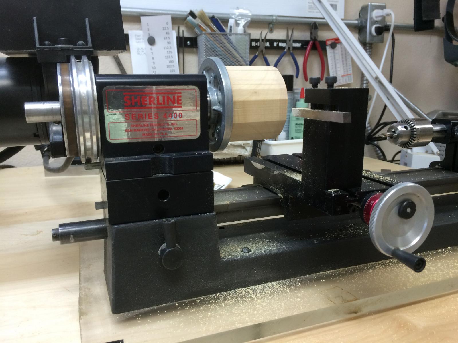
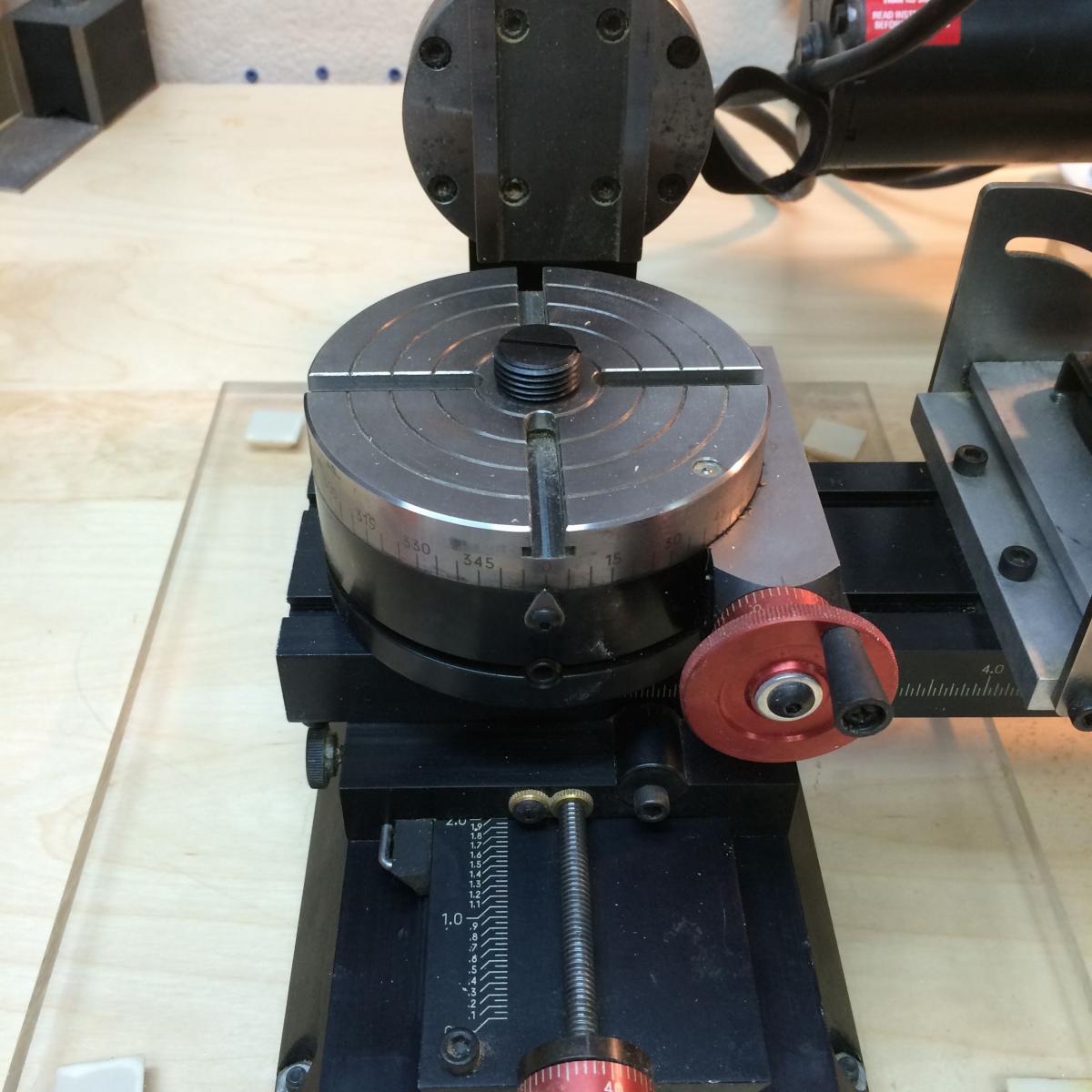
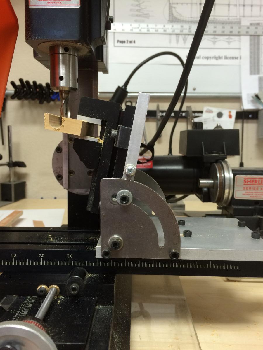
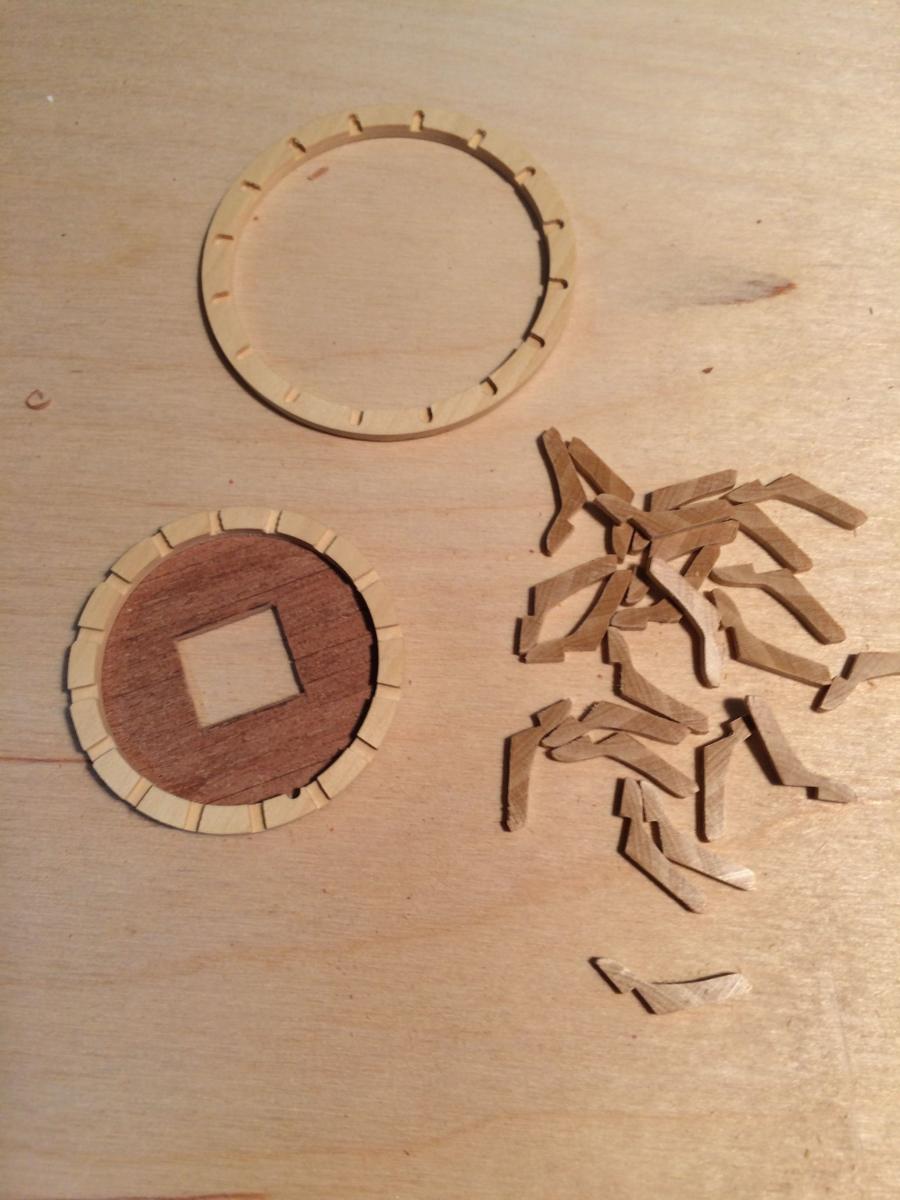
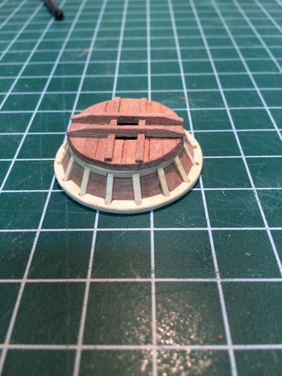
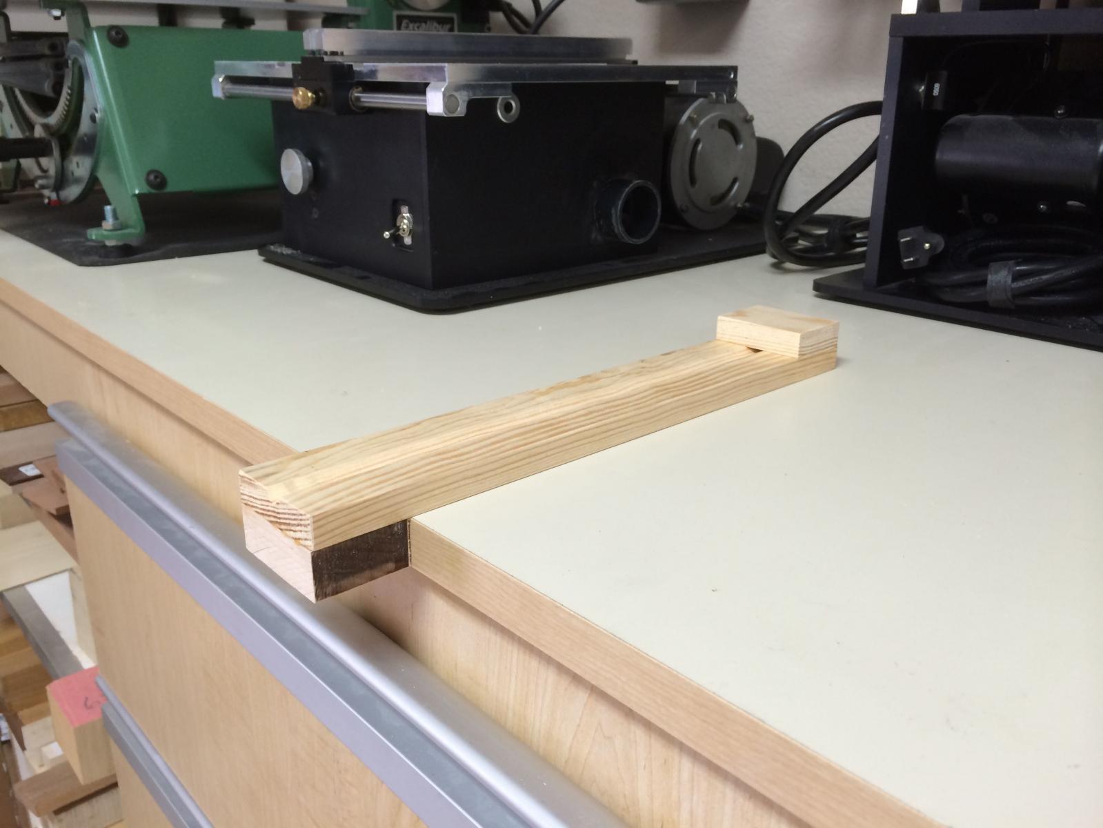
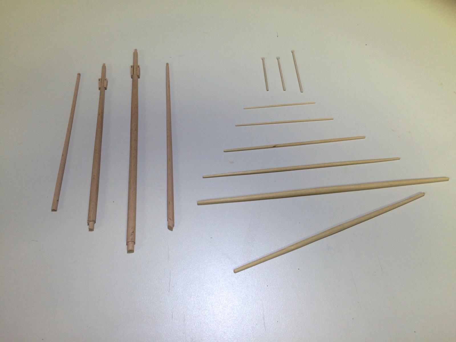
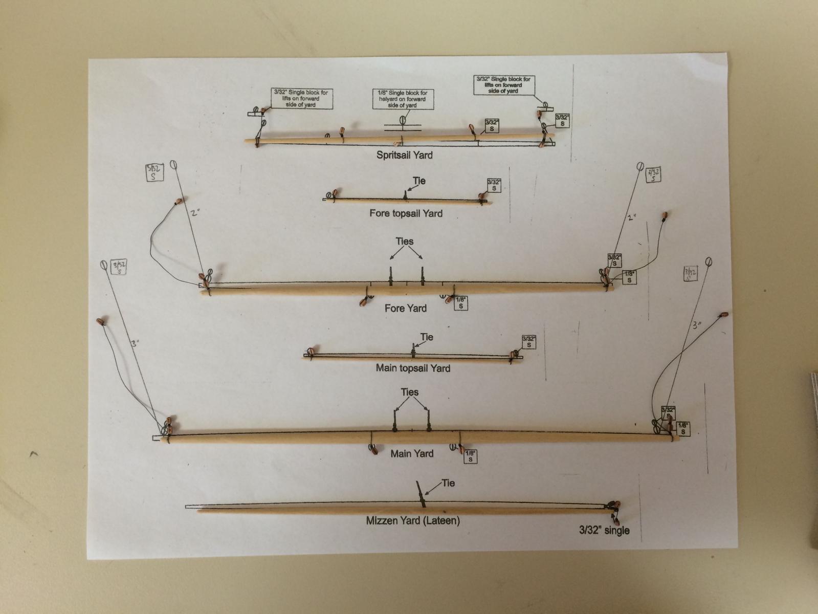
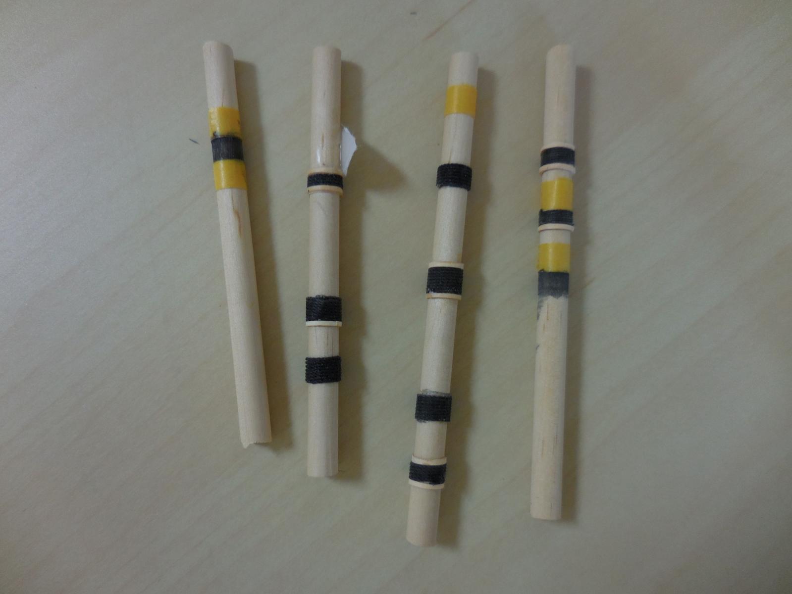
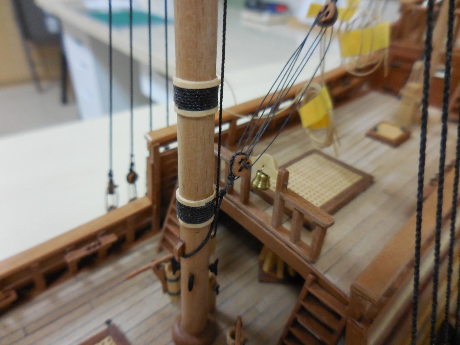
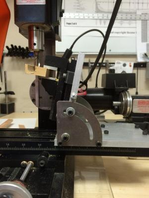
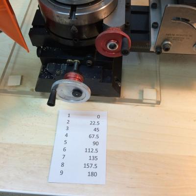
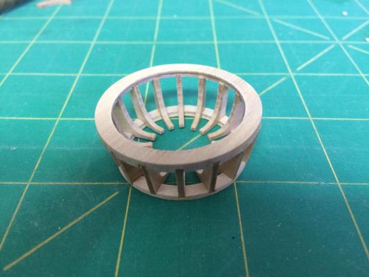
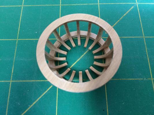
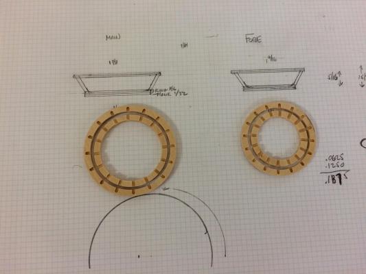
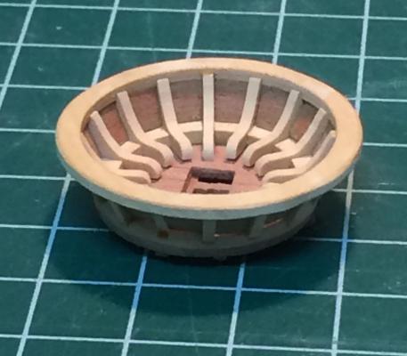
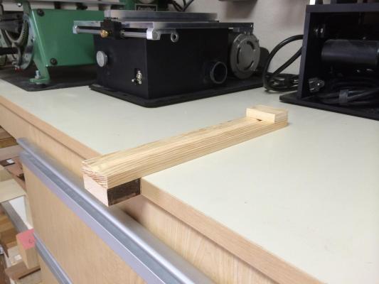
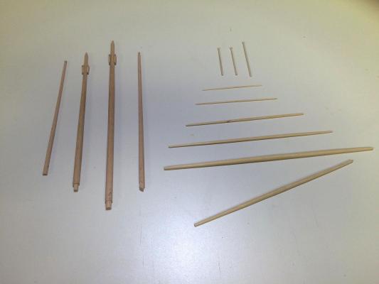
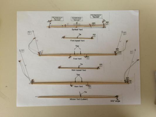
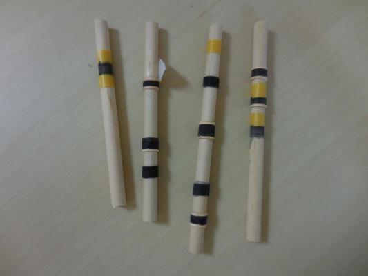
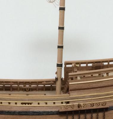
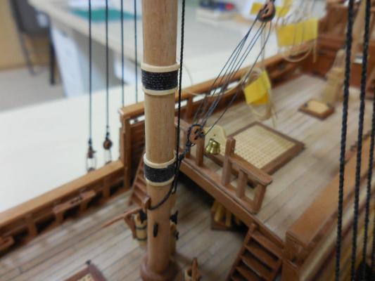
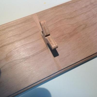
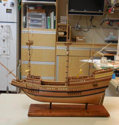
Paragon – a Modified Mayflower Part 14 – Spars Hi All It has been about a week since my last post. Sorry for the delay – life tends to get in the way sometimes! So here’s the latest update: The type of ship I wanted to make would need mast tops, and the Mayflower instructions clearly showed these. Before starting on the masts and yards, I decided to make the mast tops. The Mayflower kit used solid milled pieces as the tops, but I wanted to make the tops out of different woods and wanted to construct them as they were probably built. I found a short essay on making mast tops in one of the NRG Shop Notes books, and decided to use those notes as a guide. A detailed documentation of the process I used for making the mast tops is quite lengthy (approx 15 Mbytes as a PDF), so I won’t try to include that in this post. Instead, I’ll provide a summary. The detailed description can be found at the following DropBox link: https://www.dropbox.com/s/ehxulpcim57izps/MAKING%20MAST%20TOPS%20FOR%20THE%20MAYFLOWER%20MODEL.pdf?dl=0 Making the Mast Tops involved the use of my lathe with a riser block (which allows stock of greater diameters to be turned) It also included the Rotary Table on the milling machine and the Tilting Angle Table. Since there were 16 uprights, each upright would need to be at 22.5 degrees from its partner. This required a crib sheet, rather than trying to keep the math in my head. I needed to prove out my planned process, so I produced a prototype Mast Top. The size and angles of the top were not important, I was testing the process I planned to use. The prototype turned out pretty well, so it proved the process. The following photo shows the Top and Bottom rings for each mast top, along with the sheet I used for calculating the sizes of the tops. The rings were the critical components for the Mast Tops, but there were other components needed – the floors of the tops, the trees under the floors, the uprights, and the walls between the uprights. I was happy with the finished product. Once the mast tops were completed, I could turn to producing the spars required for Paragon. I used square stock. First I marked each piece for the required taper and cut the taper using sharp chisels and a jig for holding the pieces. When the spars had the correct taper, I then cut them to octagonal shape using the 7-10-7 rule. I used a printed sheet I received at an Admiralty Models workshop, and cut the spars using the chisel and jig shown above. 7-10-7 Sheet.pdf The topmast yards for both masts were quite small, but I was able to produce them using the same process as the larger yards. The following photo shows all of the spars except for the fore and main topmasts: After making all of the yards I attached the various blocks to them before installing them on the ship. I had never made wooldings before, so I spend some time experimenting with them, using test pieces to verify my thoughts on how to proceed. The bands were made form manila folder stained to match the wood of the masts. They are not a perfect match, but I’m happy with the appearance of the masts. When I started making the various components for the masts I realized that there were a lot of pieces that needed to come together, so I made a chart to keep track of what needed to be done. When all was completed it seemed like the end of a fairly long project. The following photo shows the masts stepped on the ship. The yards are already installed, via pins to hold them in place, and some pre-rigging has been attempted. Next post will be about making and fitting out the channels, and installing the deadeyes on the Mast Tops.


- 170 replies
-
- 10
-
-
Hi John Glad I was able to help. Another JAX product that I really like is their Brass and Copper cleaner. When I use it, I scrub it on the piece using an old artist's paint brush that has been cut down to about 1/8" of bristles. I had some brass pieces that I didn't like the blackened look, so I scrubbed them down with this cleaner. It not only removed the blackening, but also removed the discoloration from being annealed and soldered.
-
I use their Pewter Black on brass and copper and it works well. I use it full strength, but I don't immerse the item in it. Instead I paint it on with a brush, and when I get the results I'm looking for I rinse it in clear water.
-
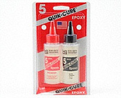
Hi Brian - now you're getting into making jigs! The glue joint might be better using epoxy glue, it's much stronger than a CA joint. I like the Quik-Cure brand. 5 minute epoxy is all you need - there are 5 minute, 15 minute, and a slow-cure. I recently got some at the Hobby Depot store we were talking about.
- 831 replies
-
- 4
-
-
- Armed Virginia Sloop
- Model Shipways
- (and 1 more)
-
Hi Brian I missed your post on your new workshop until this morning - looks great! The lighting is perfect.
- 831 replies
-
- 3
-
-
- Armed Virginia Sloop
- Model Shipways
- (and 1 more)
-
Patrick - you have me blushing! Compliments that come from folks whose work I admire are very special - thank you.
-
Rich - LOL - I hope Peter is looking in! It was great to see you today, and I hope you get over your cold soon. Completion day won't be sad at all - I'm itching to get on to the next build.
-
Bob: Between you and Patrick you're intimidating me with the small scale excellence. Looking forward to seeing your latest in person - maybe this coming week. I'll PM you.
- 127 replies
-
- 4
-
-
- dragon class
- yacht
- (and 1 more)
-
Thanks Mark and Bob. Lots of fun and lots of learning (most times learning the hard way, lots of do-overs).
-
Hi Patrick OK, so here are some questions: What do you normally use to cut these super small pieces? (hobby knife, scalpel, straight razor ....)? I'm assuming any sandpaper under 400 would be very aggressive on these tiny pieces. What grades do you use, and do you make tiny sanding sticks? Since most straight edges and squares are much too big for some of these small pieces, how do you stay straight when cutting? As I think of some more I'll pester you a little more.
-
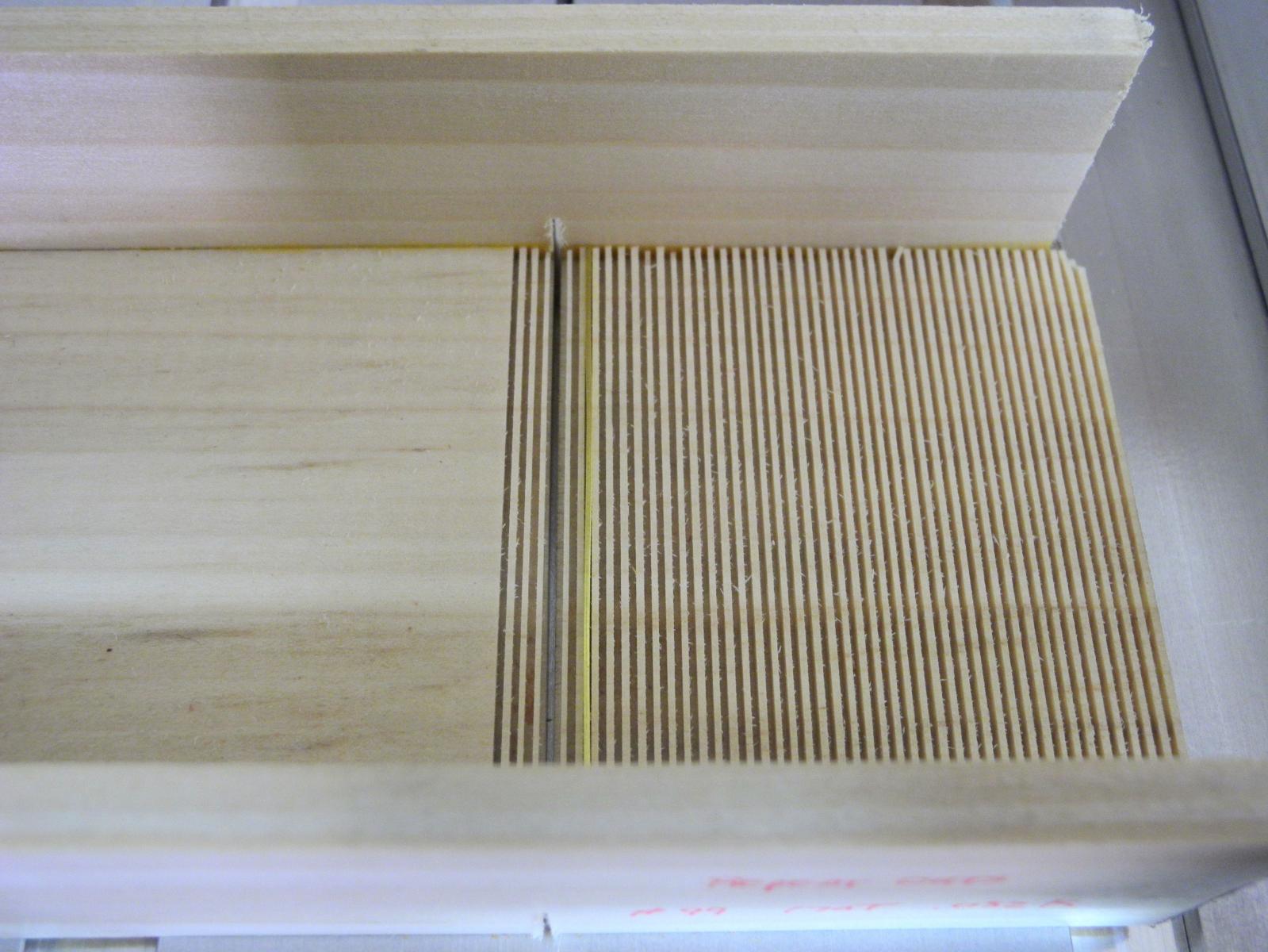
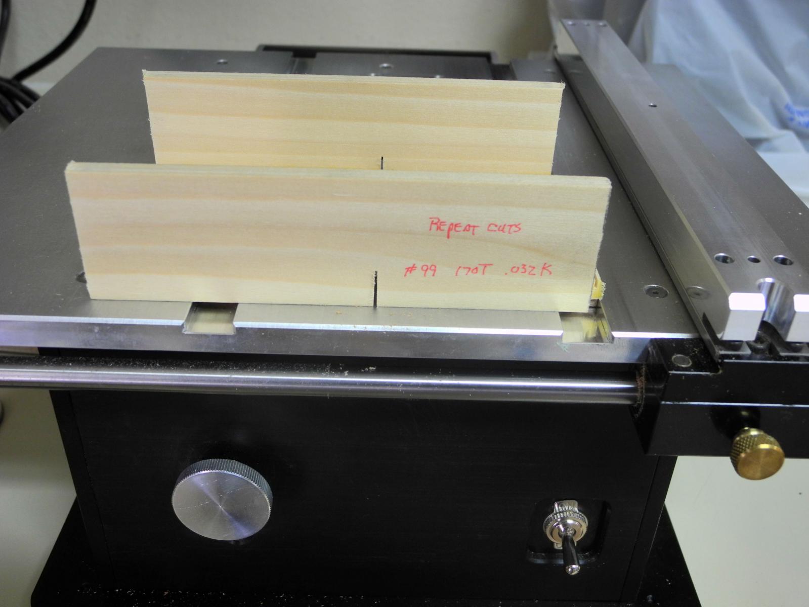
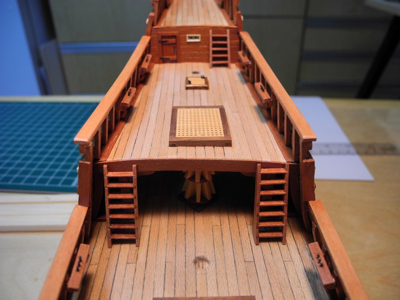
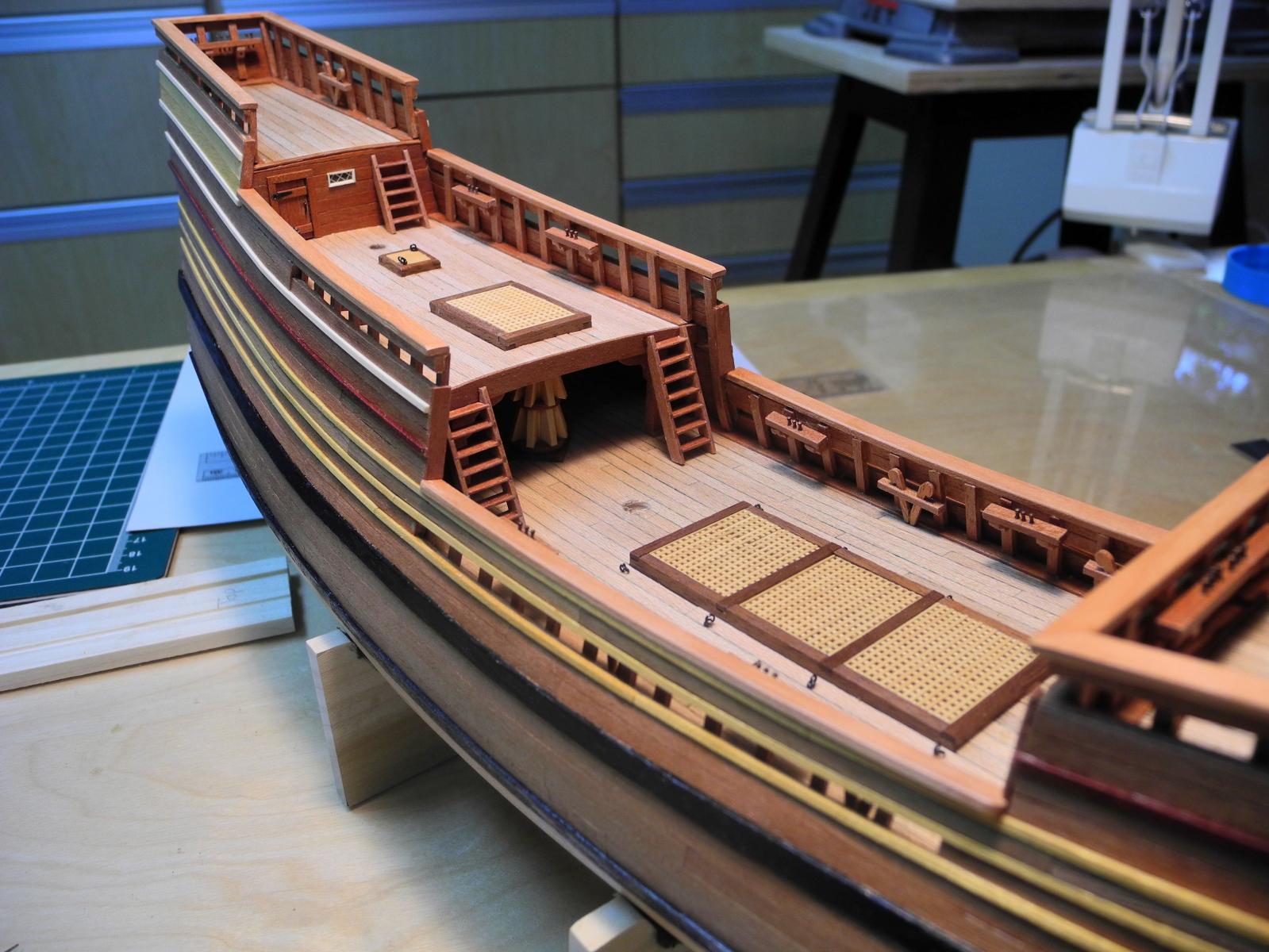
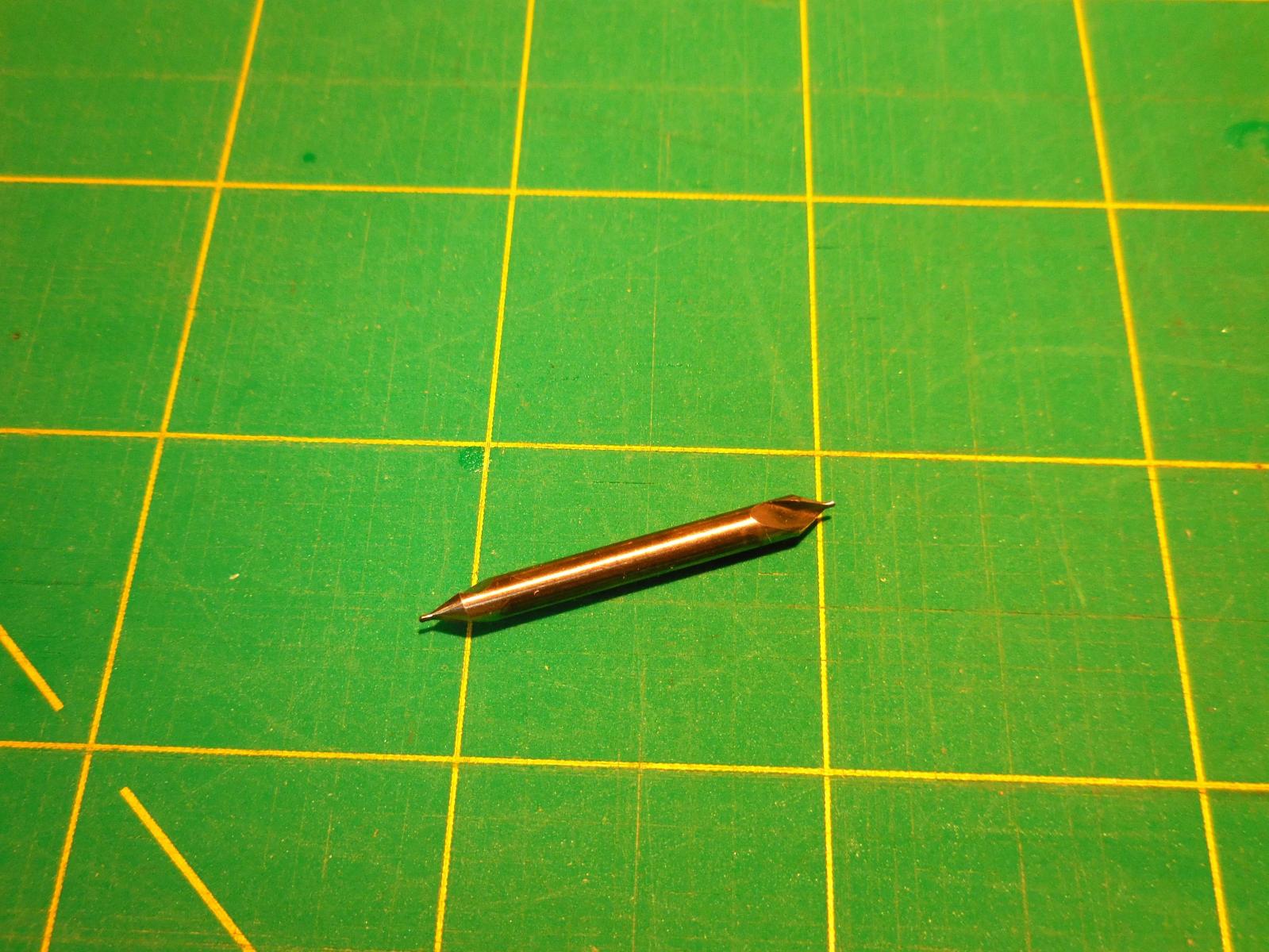
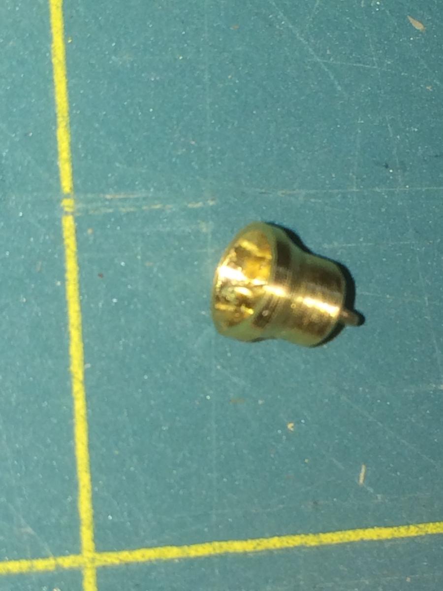
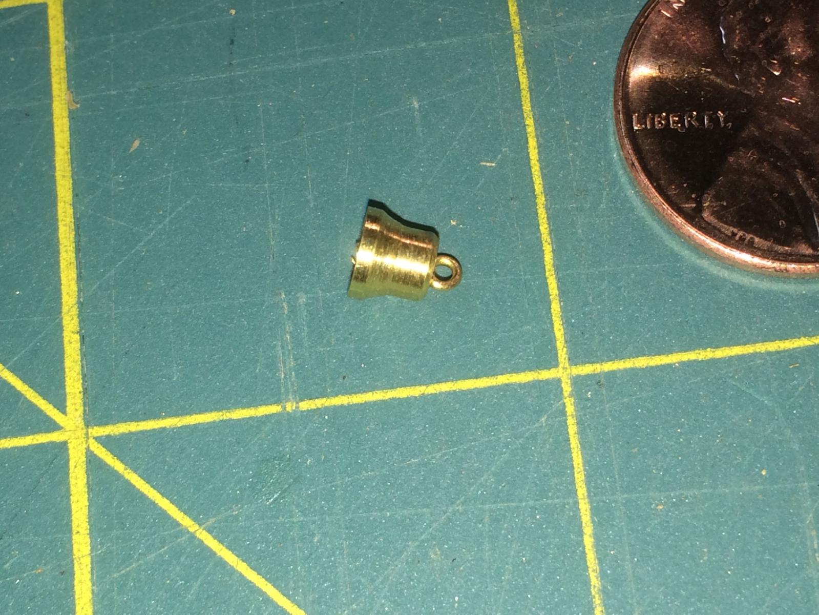
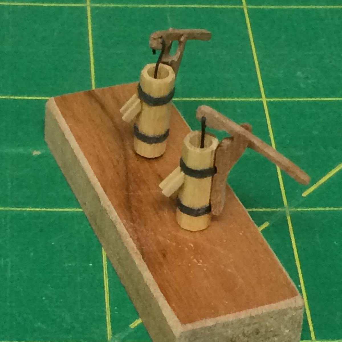
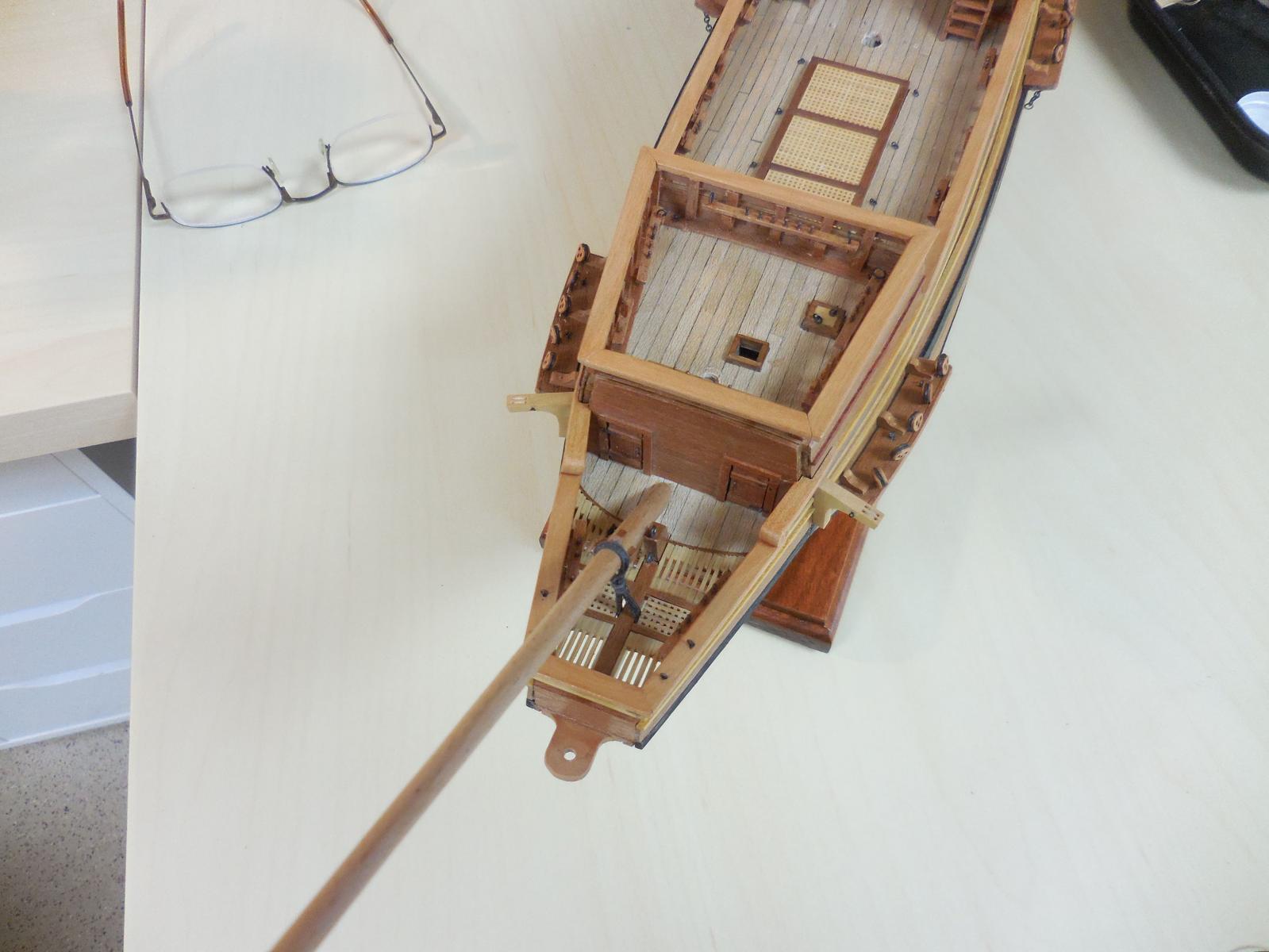
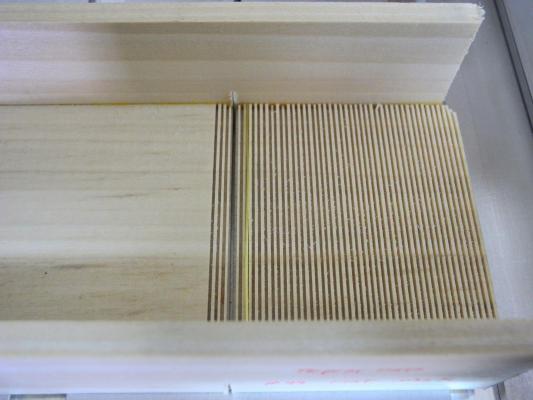
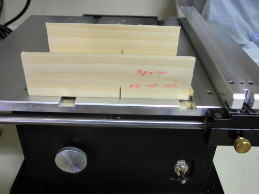
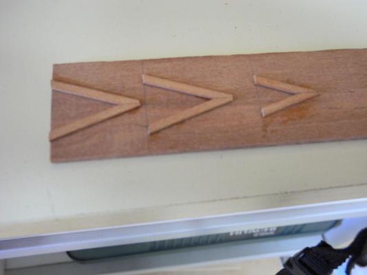
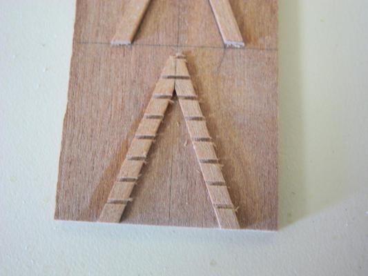
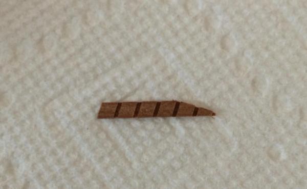
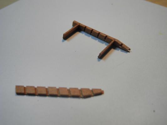
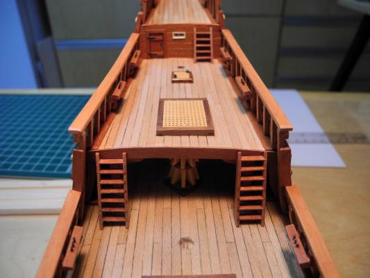
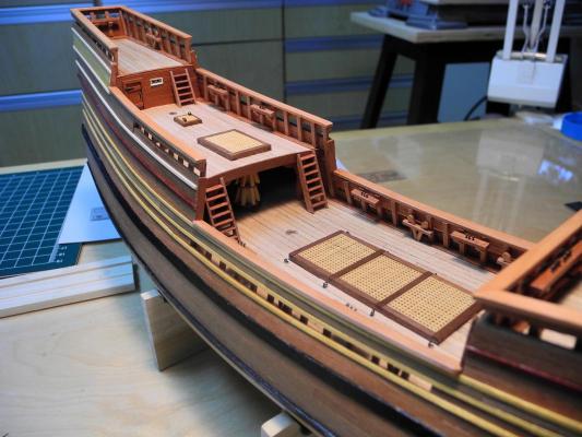
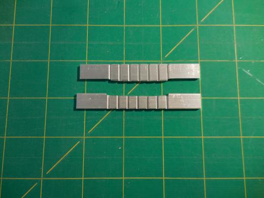
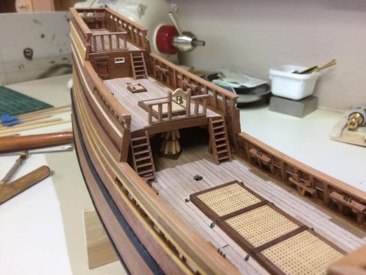
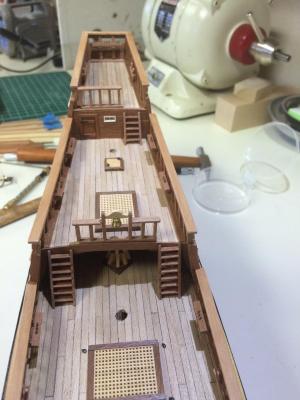
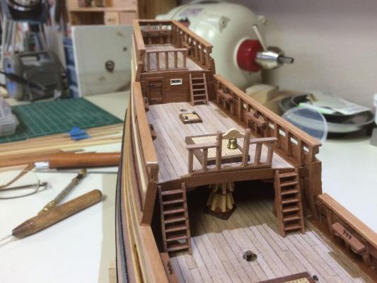
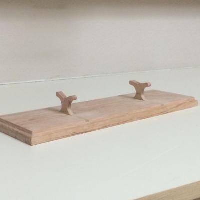
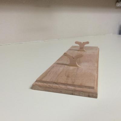
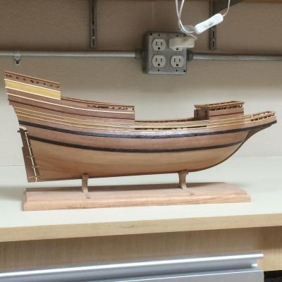
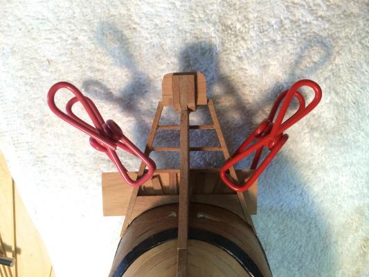
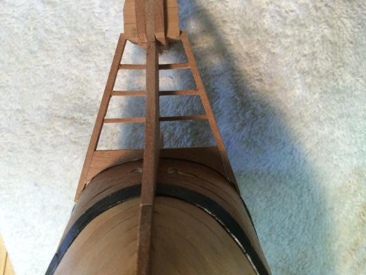
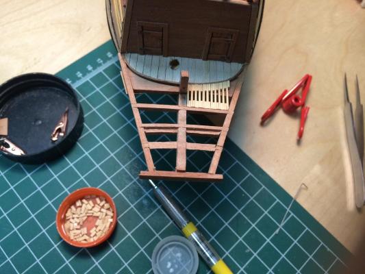
aragon – a Modified Mayflower Part 13 – Ladders, Pumps, Bell, Railings, etc Ladders The ladders were built according to the instructions. Cuts would be made in the ladder sides, so that the treads could be added. I knew I needed a way to make these cuts spaced consistently. To do so I made a sled for the Byrnes saw that was similar to the sled for the gratings. The difference was that there are a number of cuts in the base of the sled that are 1/32 apart (I made these cuts with the sled for the gratings). By placing a small brass strip in any of the cuts, I could replicate the distance between cuts. I cut appropriate pieces for the ladder sides, and glued them to a flat piece of wood using Ambroid glue. I then ran these strips through the saw using the sled described earlier. I made the side pieces for one ladder at a time, and dissolved the Ambroid glue in an acetone bath. It was pretty simple to create the ladders. The top and bottom treads were installed on one side. When the glue set, the second side was added. From there on it was a matter of sliding each tread into a slot. The legs of the ladders needed to be trimmed to match the deck camber before installation. This was done a little at a time, trial fitting after each trimming. Ship’s Bell The bell was turned on my Sherline lathe (it actually was one of the first things I did on the lathe). A small piece of 3/32 brass rod was used. The first step was using a center drill to create the opening in the bottom of the bell. These drills are used for starting holes. The bodies are thick so that the drill doesn’t waver like regular drills will when they first start contacting the surface to be drilled. The angle between the point and the body is also sharp so that the drill can be used as a countersink. Since the body of the drill is angled, the hole the drill made in the rod was also angled. After drilling, the bell shape was made using a file, taking very little off at a time until a reasonable bell shape was created. When I parted off the bell I saw that the drill had gone in deeper than I had shaped the bell, so that there was a very small hole left in the top of the bell. This was perfect for fixing the small ring at the top of the bell (I could say that I meant that all along, but probably wouldn’t get away with that for long). The bell looks a little large to me, but in this scale it represents about 8 inches in diameter, which sounds reasonable. Pumps There are two pumps that sit at the base of the main mast. I made these out of castello, since it shapes cleanly. I used a 3/16” square piece of castello, hollowed out on the lathe using an appropriate size drill. I then cut it into an octagonal shape using the 7/10/7 rule. The pump handles and brackets were made from African pear (and no, they don’t work) and the ‘iron’ bands were made from black paper. I decided not to install these pumps until after the main mast was stepped, since they’re pretty delicate and also very near the mast. Railings The difficult part of making the railings was getting the uprights all parallel and evenly spaced and perpendicular to the railings, while also having the base conform to the curvature of the deck camber. After several failed attempts I devised a couple of gluing jigs that would hold things in place until the glue set. I made the jigs out of small aluminum strips, cutting the channels for holding the uprights on the mill so they were properly spaced. I marked the camber on the strip and shaped it with a hand-held rotary tool. The jigs did their job, as all good jigs should. Base I wanted a base that would provide stability and contribute to the looks of the model. I decided to make mine out of maple, since I found a nice piece with a very nice grain in it. I didn’t want to use brass pedestals, so I shaped some maple to fit the contours of the hull bottom, and routed a channel for these pieces to be inset into the base. Although the grain of the base is nice, the tones of the wood didn’t match the ship’s colors. The base of a ship, or any piece of art, needs to complement the piece it holds. I mixed a stain by combining Minwax Sedona Red and Golden Oak – this solved the problem. I’m pleased with what the base adds to the presentation. Here’s a photo taken after stepping the masts. Next up – making and fitting out the spars.


-
Hi Patrick Been pretty busy - hopefully will have another update later today. I use Optivisors also - I use the number 7 lens. I'd love to fire off a number of questions on how you do such great small work - would you mind?
-
Ed - I hope you'll be autographing copies of the book at the NRG Conference. I'm looking forward to meeting you there.
- 191 replies
-
- 1
-
-
- young america
- clipper
- (and 1 more)
-
Proxxon EF vs. Dremel 7700
Mahuna replied to rtropp's topic in Modeling tools and Workshop Equipment
Hi Richard The Foredom I was thinking of is the Micromoter - you can do very precise work, and the variable speed foot pedal gives great control.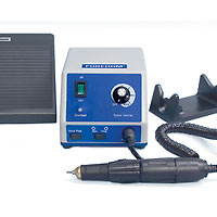
-
Proxxon EF vs. Dremel 7700
Mahuna replied to rtropp's topic in Modeling tools and Workshop Equipment
Gesswein and Foredom both make rotary tools that are at a higher level in terms of power, precision, and speed. If your budget allows, I would recommend the tool shown in the attached link. -
Micro Drills, Revisited.
Mahuna replied to Modeler12's topic in Modeling tools and Workshop Equipment
Hi Richard - I use those bits too, and I like them, but I've found that they're very brittle and need to be held in a drill press or milling machine. Hi Jay: I also use HSS drill bits with 3/32 shanks for all of my hand power drilling. This is the set I have: http://www.woodcarverssupply.com/30-PIECE-DRILL-SET-3_32/productinfo/627020/ -
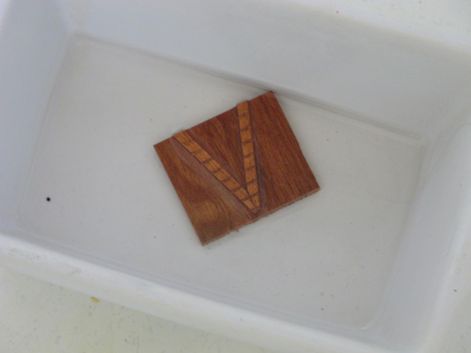
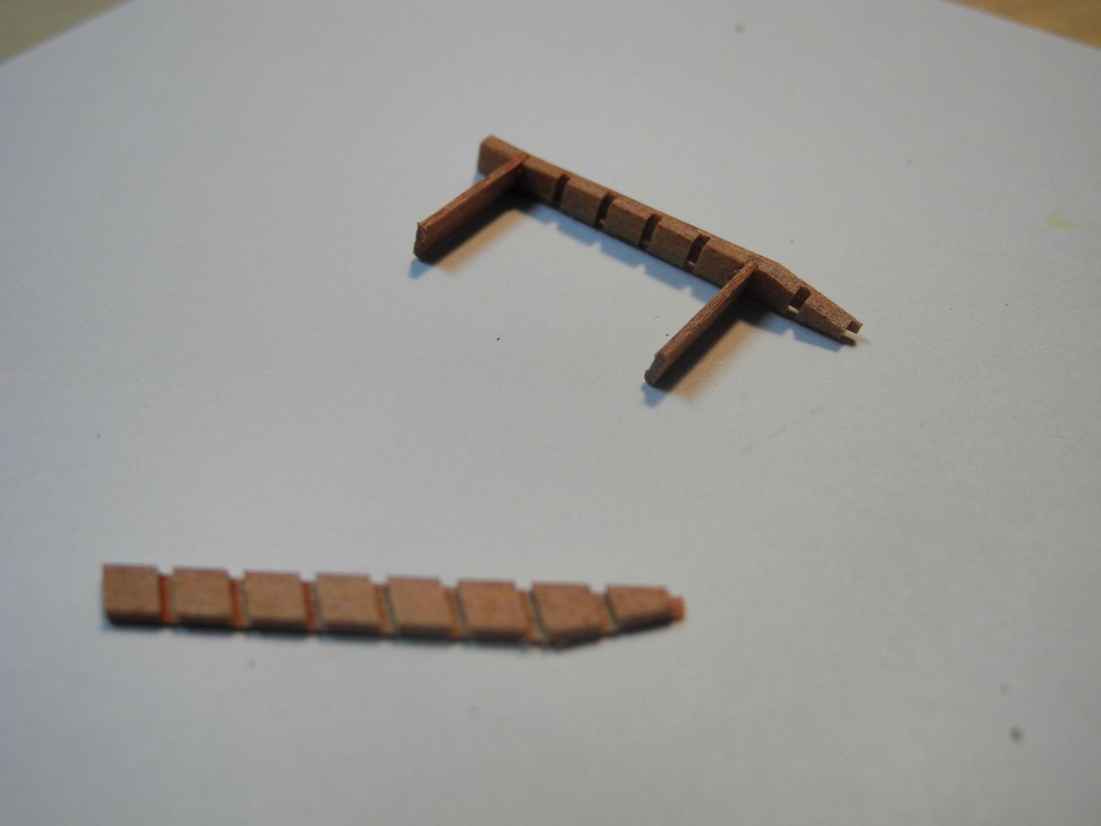
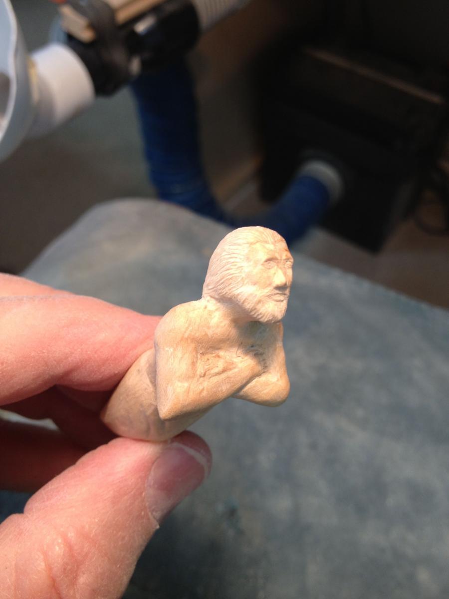
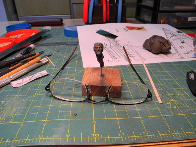
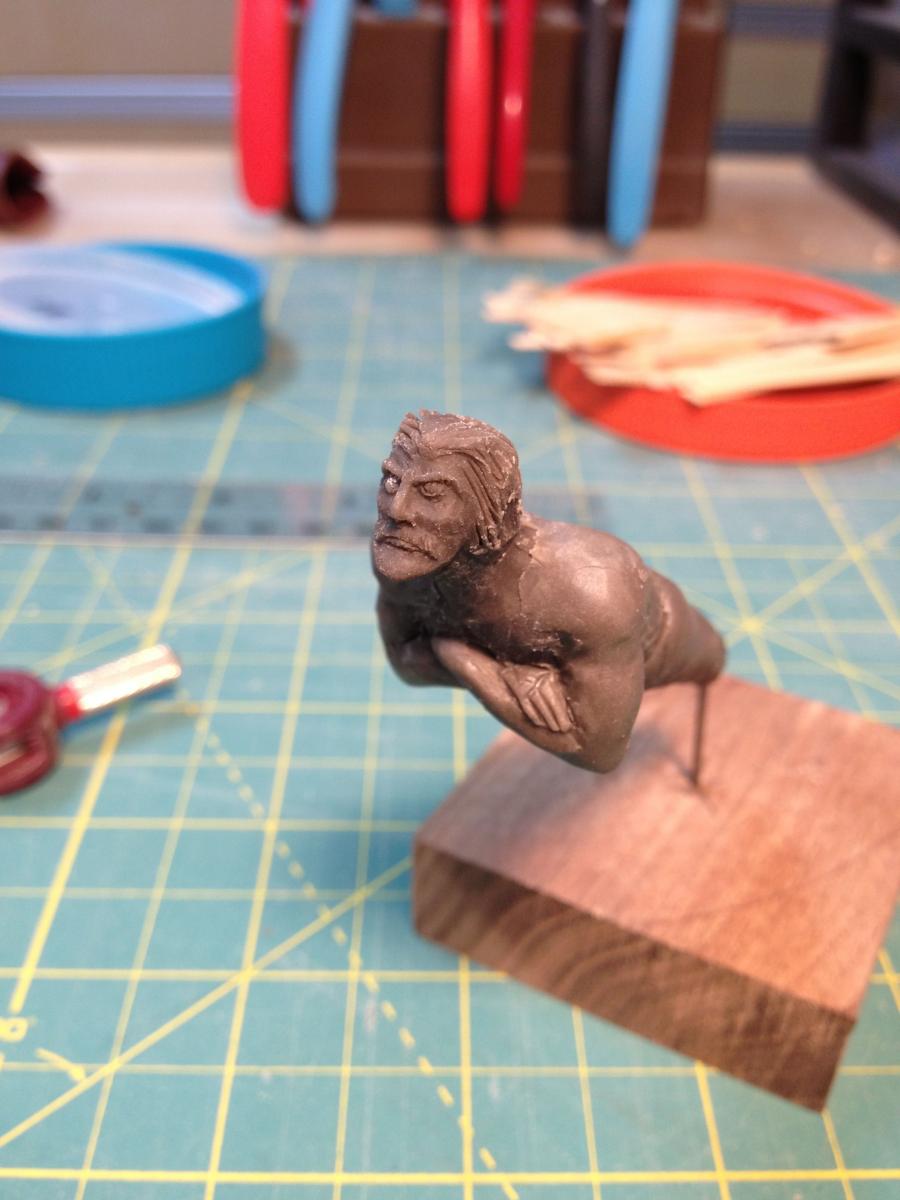
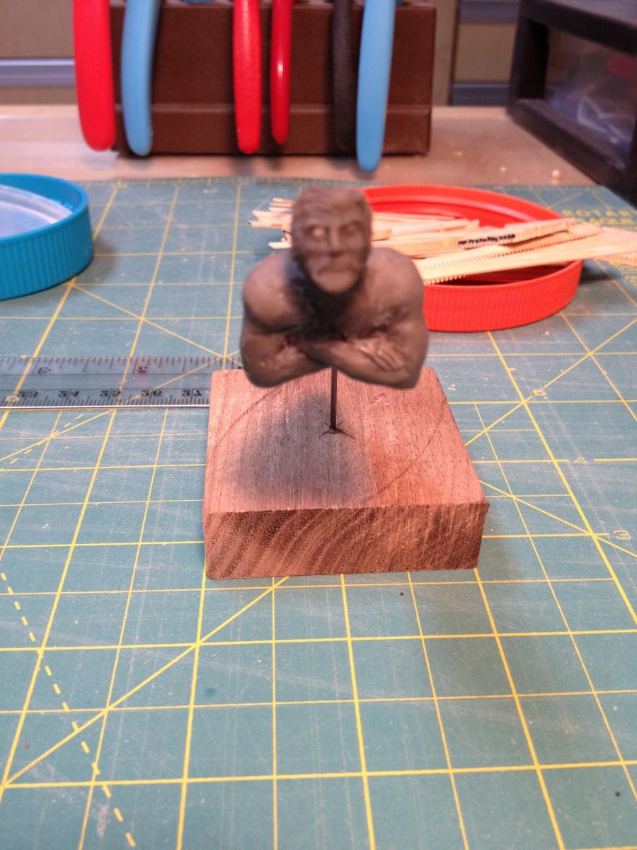
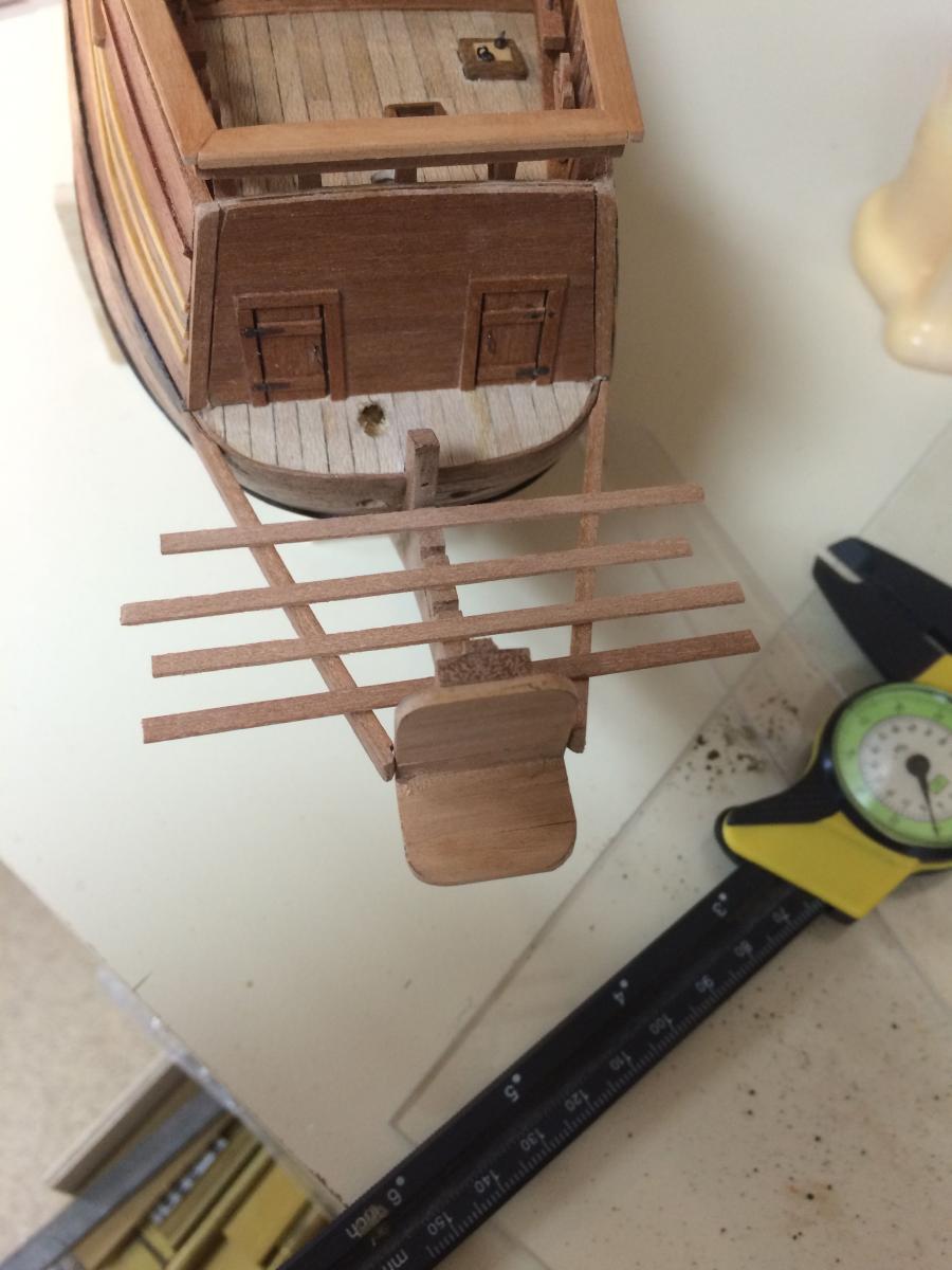
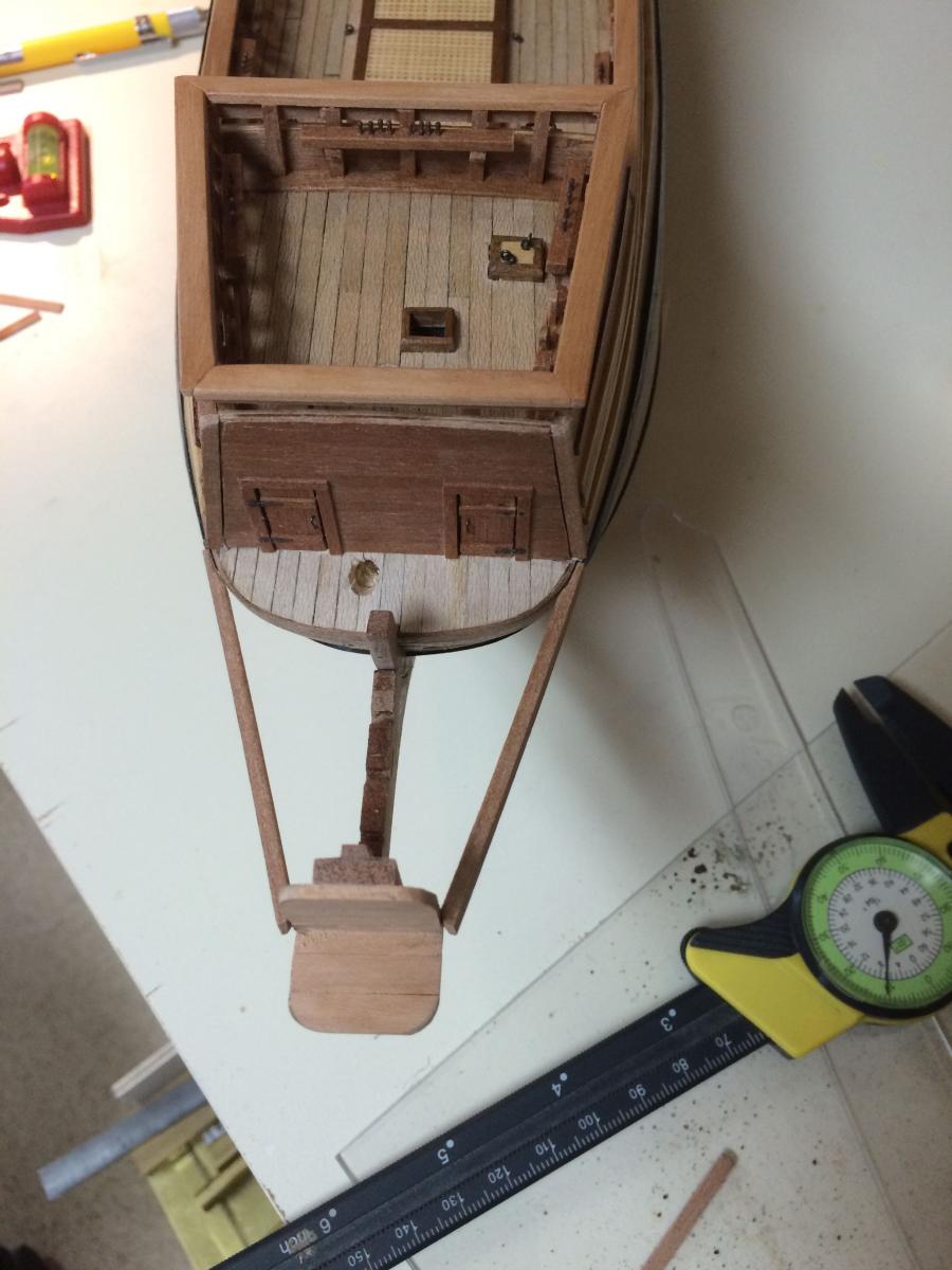
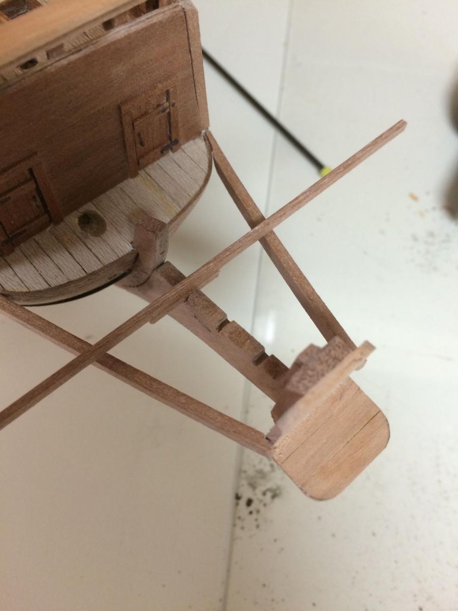
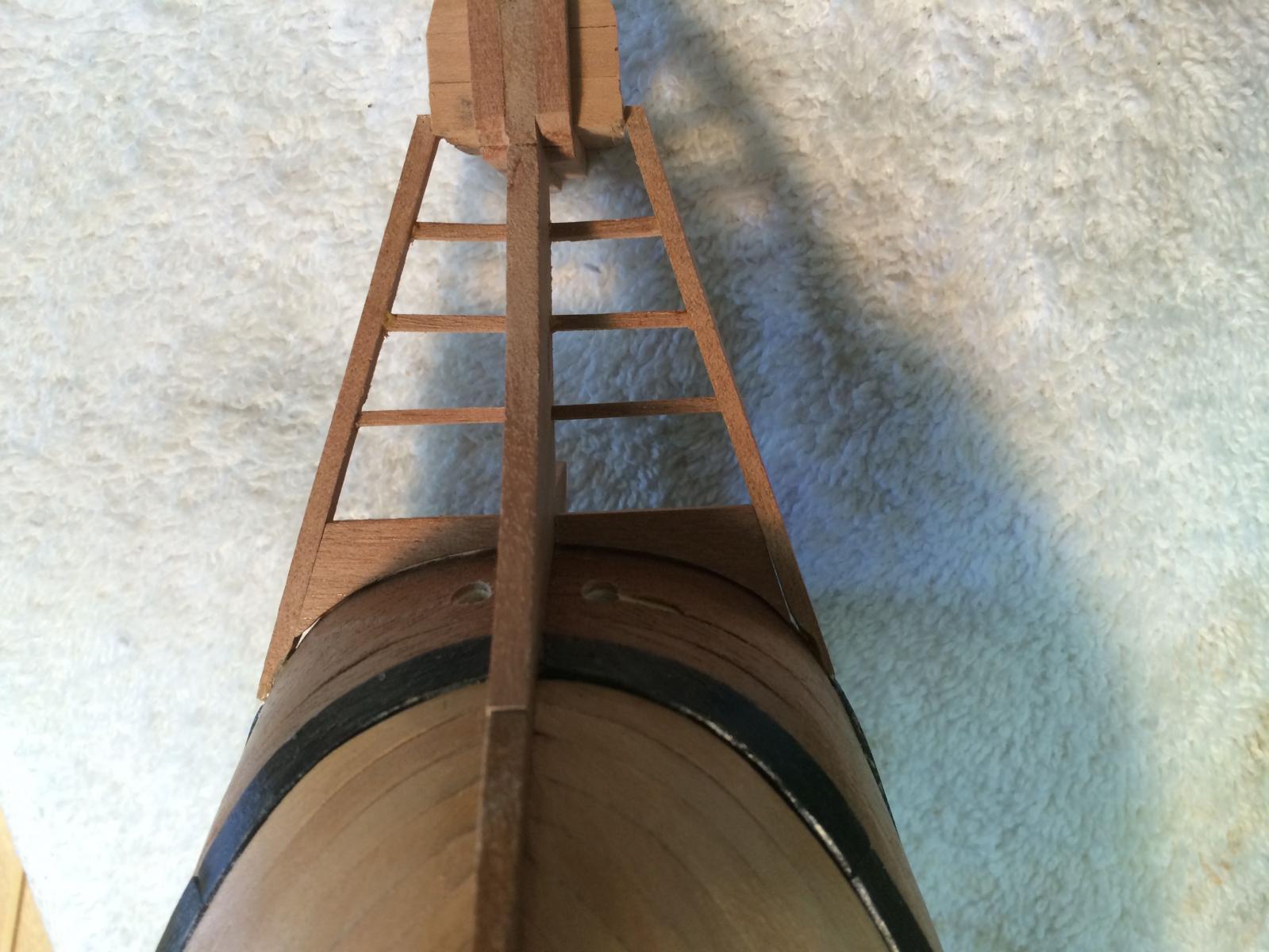
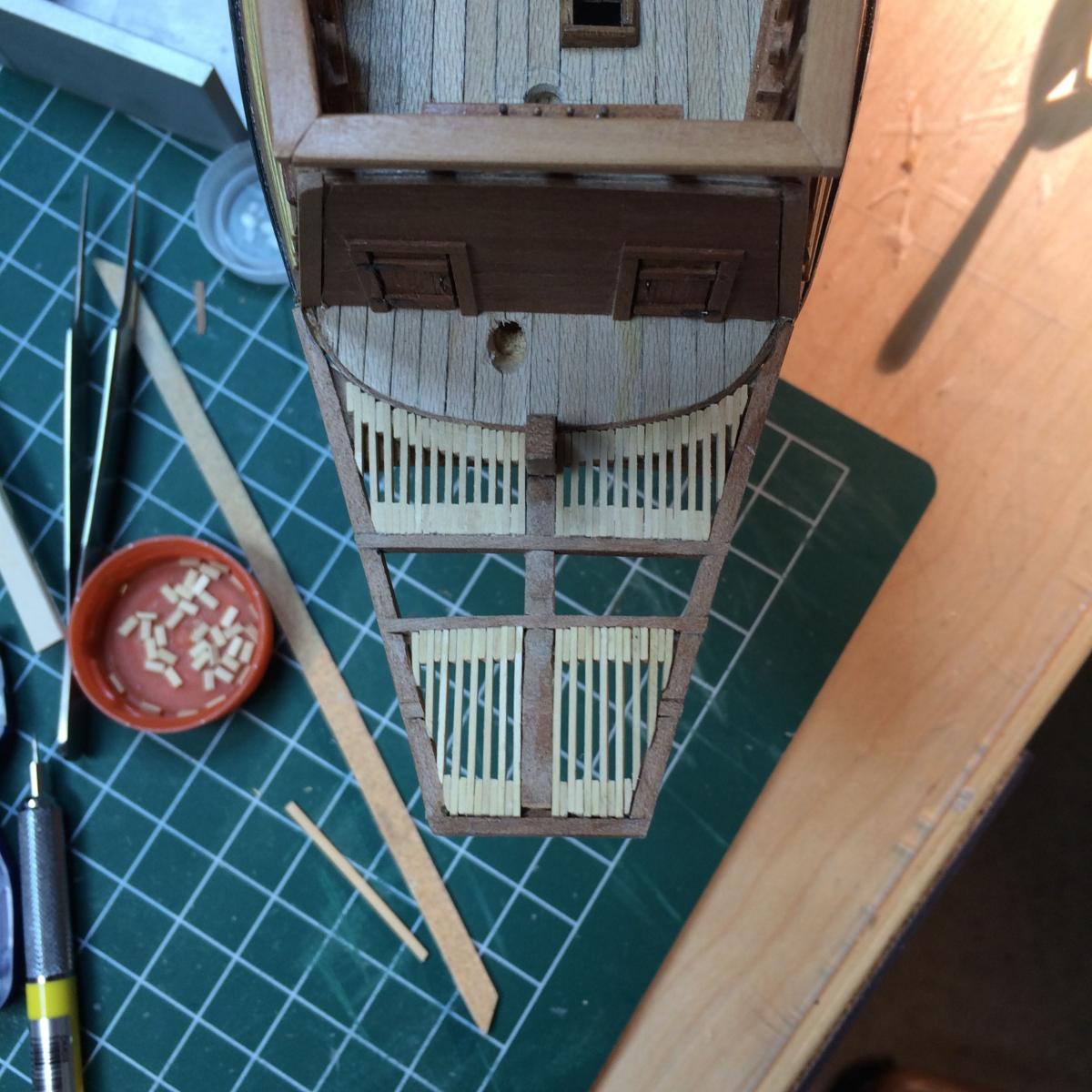
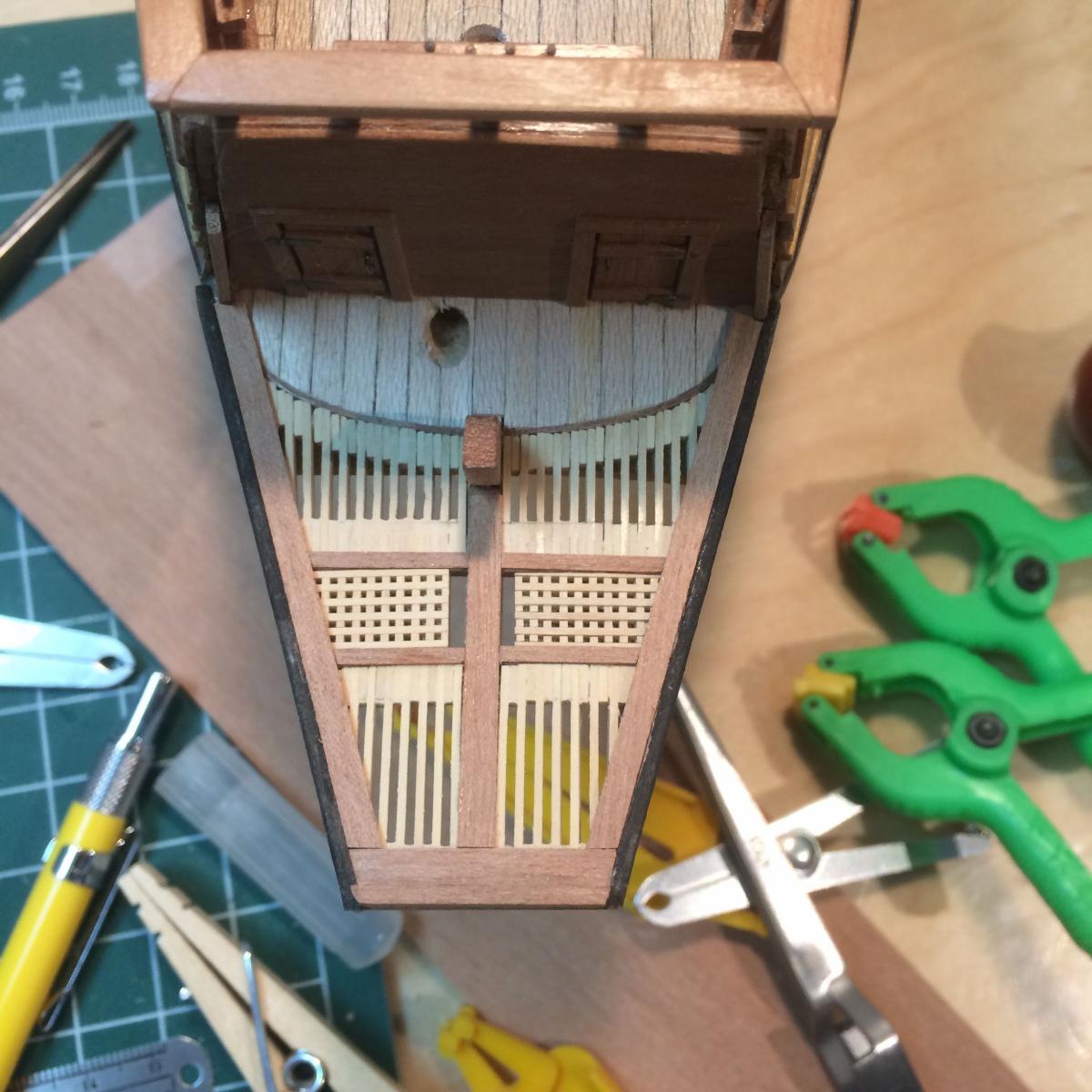
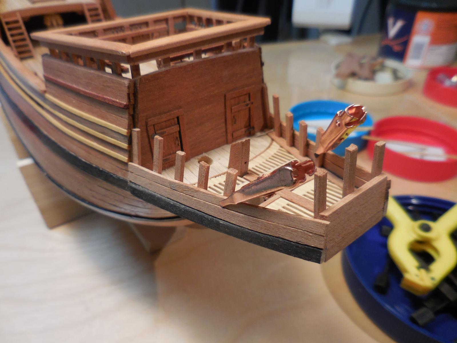
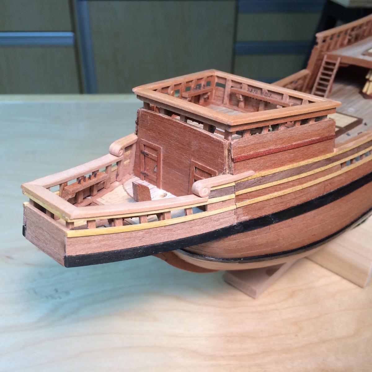
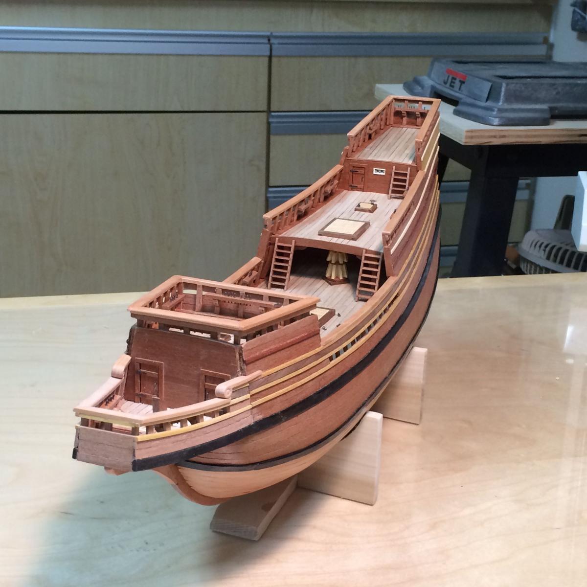
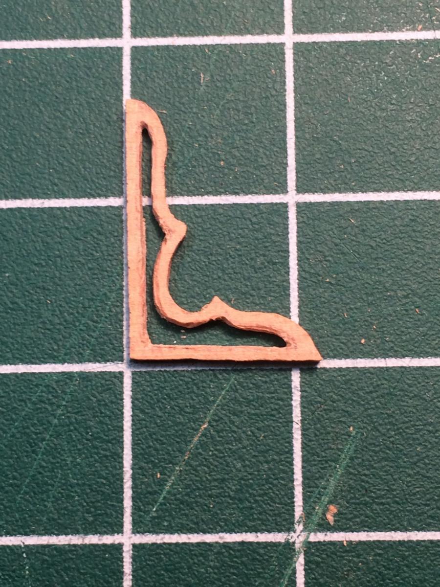
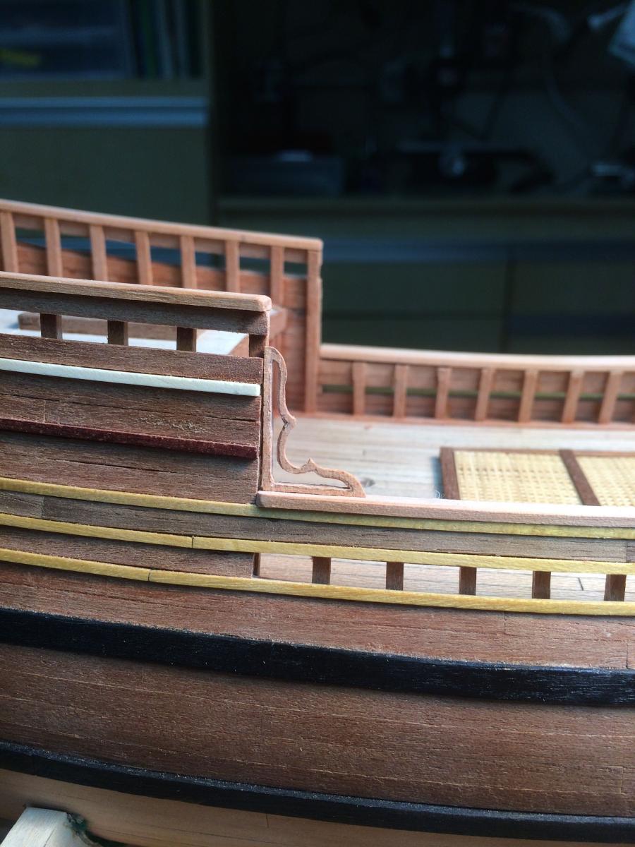
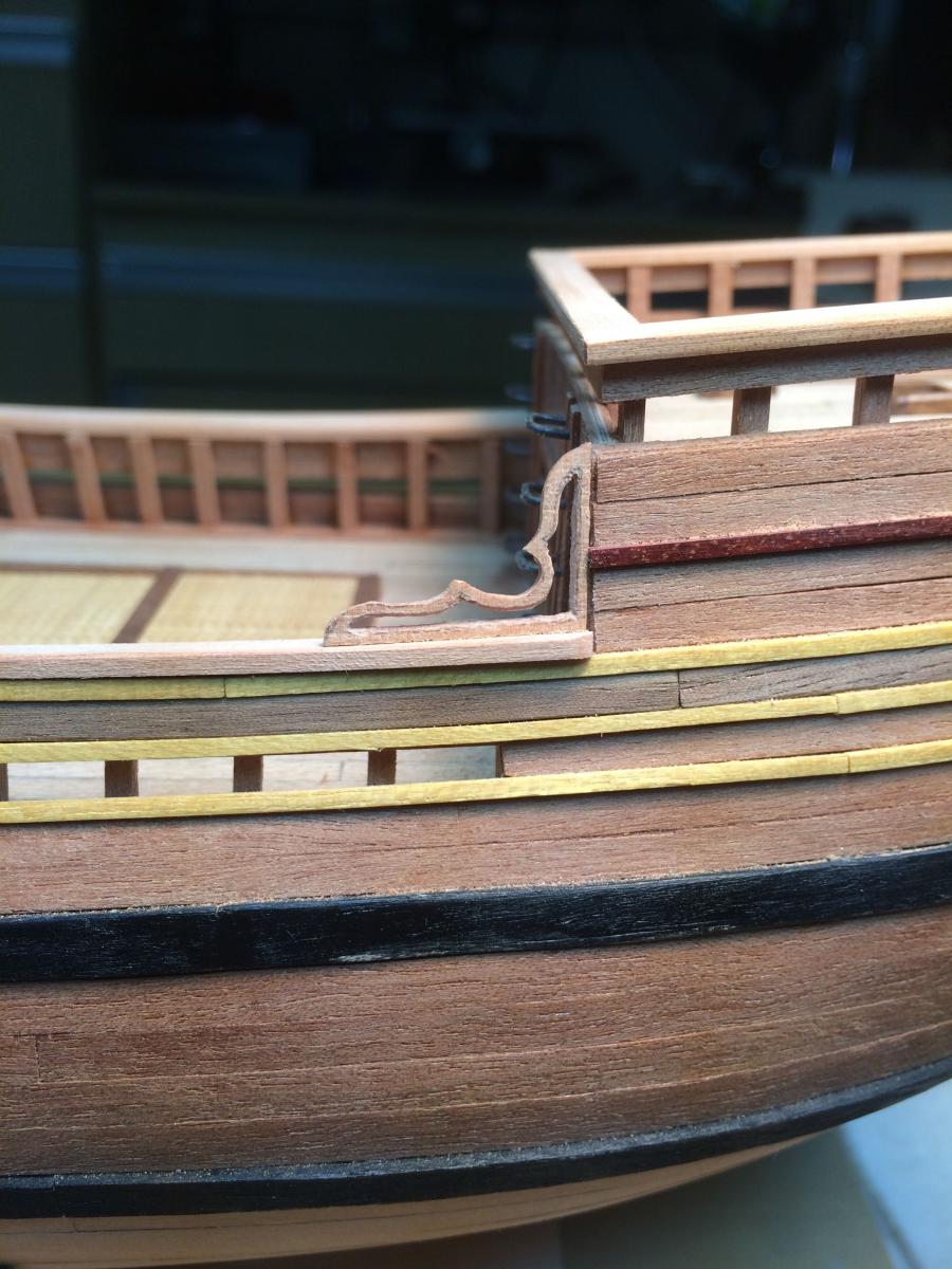
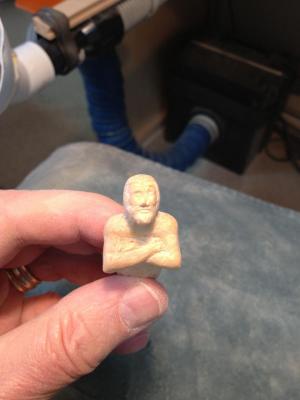
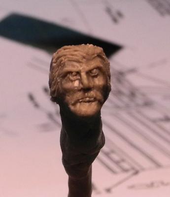
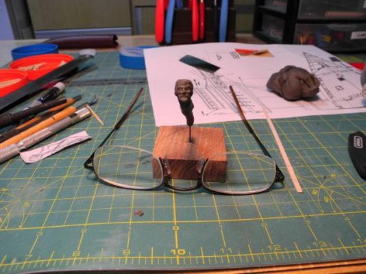
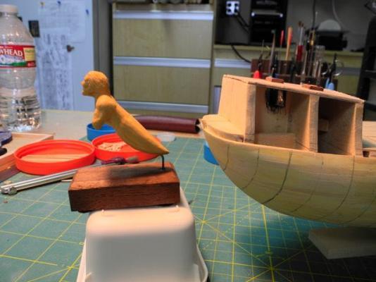
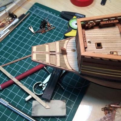
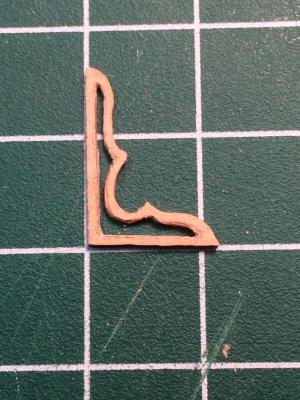
Paragon – a Modified Mayflower Part 12 - Beakhead A figurehead would be a major part of the Paragon, and since the Mayflower did not have one, I needed to make some modifications to the way the beakhead was constructed. The Mayflower beakhead, as designed, came to a fairly narrow forward end, and this wouldn’t be wide enough to support a figurehead. I thought it made sense to design and construct a prototype figurehead before deciding how the beakhead needed to change. Thinking that the figurehead should be carved from wood, I tried carving the figurehead from castello boxwood. I didn’t use any pictures as a guide, relying solely on my imagination of what I wanted the figurehead to look like. I had envisioned the figurehead as being in a semi-horizontal position, so that’s how I carved the figurehead’s position. Carving at this scale proved more difficult than I had planned (I’m used to carving larger items, like green herons, peregrine falcons, and the like). So I decided to create the figurehead from clay, thinking that I would use the clay version as a 3-dimensional model for carving the final version from wood. I modeled the figurehead from Sculpy, which is a clay that hardens when baked. (I plan to provide more details on the process when I cover the creation of the final version of the figurehead.) First I modeled the head. Still envisioning the figurehead as being in a semi-horizontal position, that’s how I modeled the body. I thought the clay model looked pretty good, so I took some photos to see how the figurehead would look on the ship (this was in the early stages of construction, before any planking began). I wasn’t happy with the result, and it was clear to me that the figurehead needed to be in an upright position. This actually made the redesign of the beakhead much easier than if I had stayed with the semi-horizontal position. I spent some time drawing plans for the revised beakhead. First I tried shortening the beakhead to the point where it was wide enough to support the figurehead. The plans and instructions called for using thin plywood templates as the base for building the beakhead, so I cut out the beakhead templates to see if it made sense to use this approach to construct the beakhead. After several frustrating attempts, I decided to frame out the beakhead rather than using the plywood templates. I shortened the stem knee, then after installing it I built a mounting platform for the figurehead at the end of the knee (I later removed this – it looked too much like a chair to me). Then I installed beams on either side of the stem knee, using battens laid athwartship to ensure that the beams were at the correct height. Then the side beams needed to be notched to allow deck beams to lie correctly. I used a batten with a small piece that would fit in the notches in the stem knee. This helped me mark the beams so that the notches would be in the right place. The beak would have slats for decking, except for small removable gratings to allow installation of the gammoning, so after installing the deck beams I needed to add ledges that would support the slats and the gratings, as in the following photos (taken from the underside of the beak). This photo shows the slats being installed and shows the ledges supporting the slats. As work progressed towards the forward end of the beak, I realized there were going to be too many divisions in the slats, so I removed one of the forward deck beams. This allowed me to install longer slats forward, which I thought looked better. The slats as initially installed were very uneven, so I used files to clean up the arrangement. I also made two small removable gratings for either side of the gammoning slot. Next was the installation of the sides for the beakhead. This started with two planks of African pear, then the installation of stanchions to support the rest of the moldings and planking. The planking and molding continued the pattern from the hull planking previously installed. (Lesson learned: it would have been much better to construct the beakhead before the final planking) I added a small fancy rail on each side of the beakhead, and carried the railing aft into the forecastle area. The following photos were taken before the beakhead was finished with poly to match the rest of the ship. You can see that the corner of the forecastle above the railings looks unfinished. The plan is to add some ‘fancy work’ in this area, but that will be delicate and won’t be added until after rigging is completed. The following photo is of a prototype for the fancy work. And here are a couple of photos where I was trying out some ideas for the fancy work. I’ve just started the rigging, and the removable gratings for the gammoning slot were very handy! The next post will deal with ladders, the ship’s bell, and other items.


-
Hi Patrick Beautiful - it's a shame to cover it, even with deck planks. I probably missed this in an earlier post, but what woods are you using at this small scale? Frank
-
Gosh, ya think? That's one of the things I love about this hobby. (And scratch building calls for more tools and jigs, by the way. You'll find out soon enough!)