Mahuna
-
Posts
1,504 -
Joined
-
Last visited
Content Type
Profiles
Forums
Gallery
Events
Everything posted by Mahuna
-
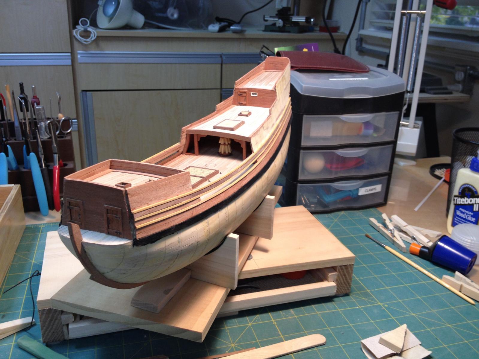
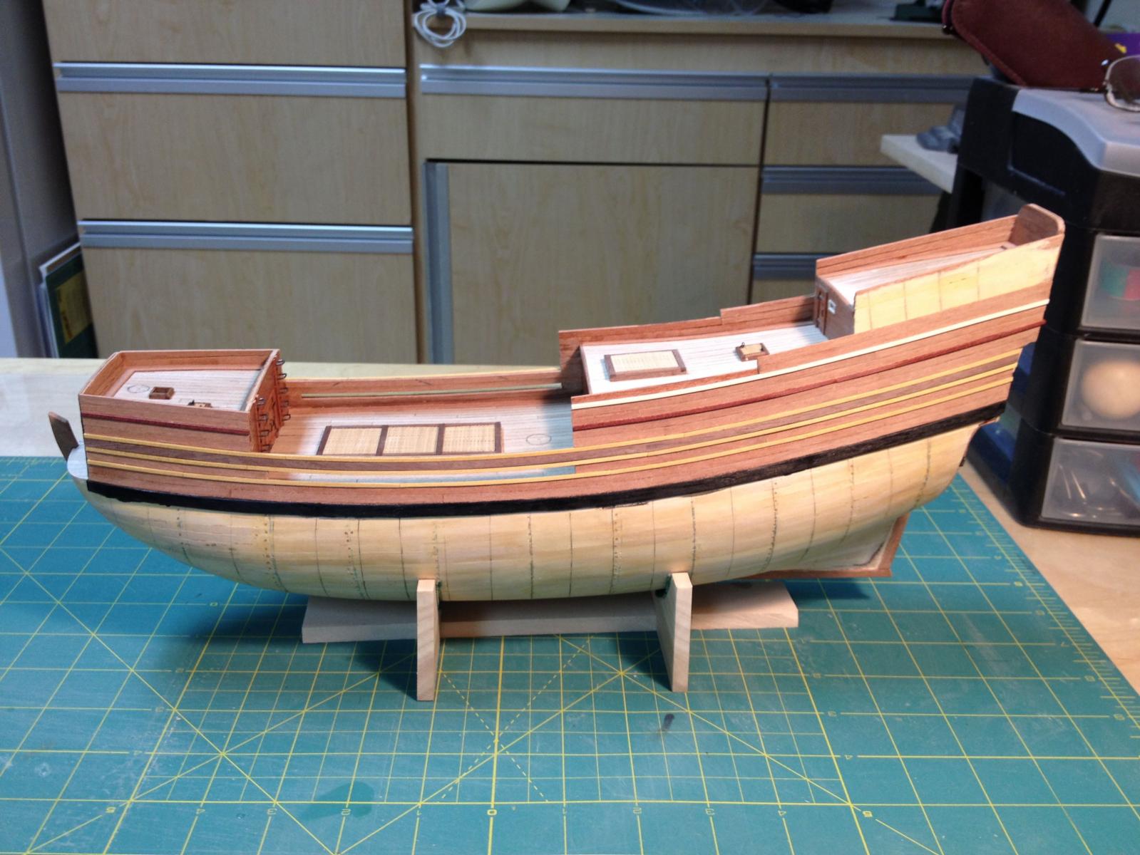
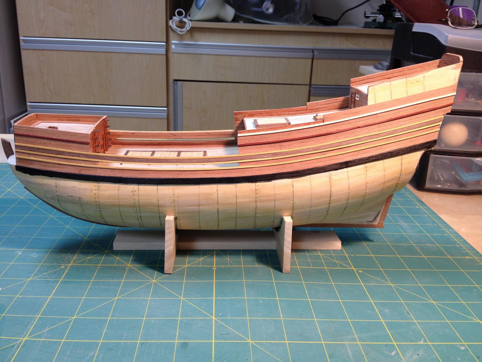
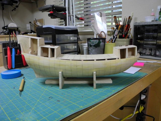
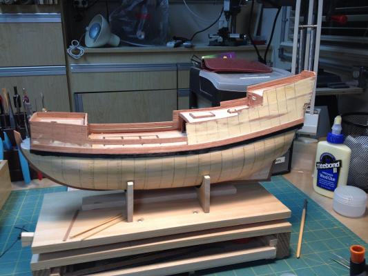
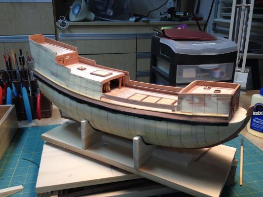
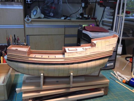
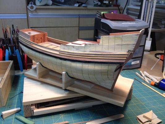
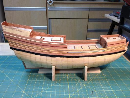
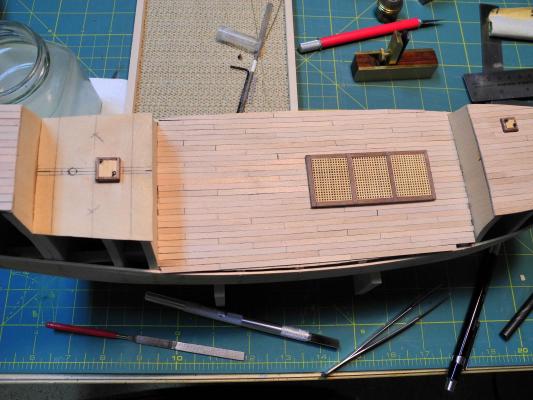
 Paragon – a Modified Mayflower Part 7 – Hull Planking - 1 I’ve read several comments by different modelers saying that the building of a ship model can (and probably should) be viewed as a number of projects, and this rang true to me when I started the hull planking. The first stage was in the design of the planking. I needed to plan out the woods to be used for the general planking and for the decorative strakes and moldings. As I said earlier, I wanted to ‘paint with wood’, and this all needed to be planned out before planking should begin. The document at the following link describes the woods that I used. https://www.dropbox.com/s/n641tqtye0sy3lh/MY%20CHOICES%20OF%20WOODS%20FOR%20PARAGON.docx?dl=0 Learning to cut consistent planks was another major effort. I’ve documented the process in a separate file that can be viewed at the following link: https://www.dropbox.com/s/1jcfdioqfs1c0c5/Milling%20Planks.docx?dl=0 There are two wales that determine the flow of the planking. The top edge of the upper wale is even with the sheer of the main deck. I used 1/8” wide artist’s tape to mark the flow of the planksheer, repositioning the tape as necessary to get a fair flow of the tape. The bottom of the tape was lined up with the top of the main deck planks. When I thought I had the flow of the tape right I nailed a 1/16 x 1/32 batten against the hull, lined up with the bottom of the tape. The wales are a consistent 3/16” wide, and are 1/16” thick. I needed to use a spiling technique to make sure they had the proper flow. I used the spiling technique described in David Antscherl’s excellent write-up, which is in the MSW Database at the following link: http://modelshipworldforum.com/resources/Framing_and_Planking/Planking%20primer.pdf After installing the upper wales I stained them to look like ebony. I could do this when they were already in place because I’d be planking over any area of the hull that got stain on it. A good friend had given me a piece of ebony, and I used that as a reference for the color. Ebony is what artists call a ‘warm black’, which has some brown tones. Note: A pure black can be made by combining equal parts of blue and brown (I use Ultramarine Blue and Burnt Umber). A cool black is made by using more blue than brown. Conversely, a warm black is made by using more brown than blue. I installed the upper wales on both sides of the hull. The wales ran from the beakhead bulkhead to the stern, covering the ends of the stern planks. Sorry – no photos of the upper wales in place by themselves, but here’s a photo of the first couple of strakes of planking with the upper wales. I installed the planking on both sides of the hull as I went along to keep the strakes lined up as much as possible. I planked the hull above the upper wales first, and all planks were a uniform thickness of 1/8” for the entire run of the strake. I did need to do some edge bending of some planks, but this was not extreme and was done by soaking the plank in hot water and then carefully shaping it over a heated plank bender. When I reached the point that the ship was planked to the top of the forecastle I started planking down from the upper wale, which is the subject of the next post.


-
Brian Don't buy if you can borrow! You're welcome to use any of my accessories before you decide to buy them.
- 831 replies
-
- 2
-

-
- Armed Virginia Sloop
- Model Shipways
- (and 1 more)
-
Hi Bob It looks like this will be a very delicate build for a while. I'm looking forward to seeing how you develop the hull strength.
- 127 replies
-
- 3
-
-
- dragon class
- yacht
- (and 1 more)
-
Brian: Next time you're here I'll show you the Sherline wood tool rest. Frank
- 831 replies
-
- 1
-
-
- Armed Virginia Sloop
- Model Shipways
- (and 1 more)
-
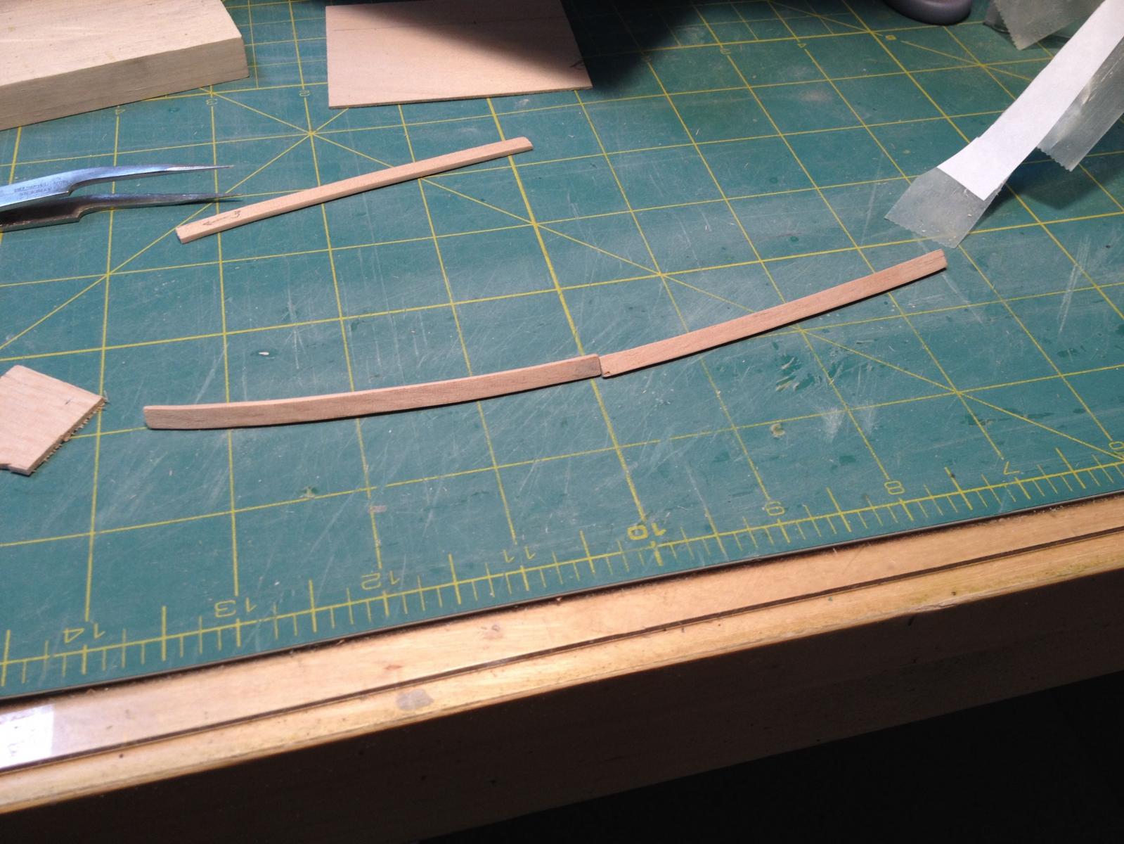
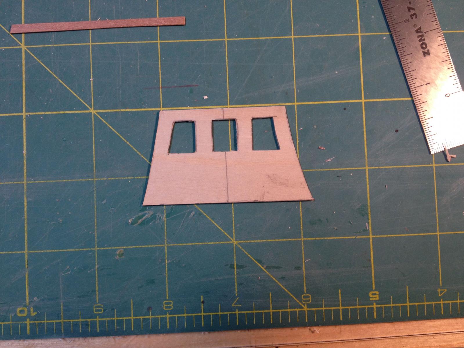
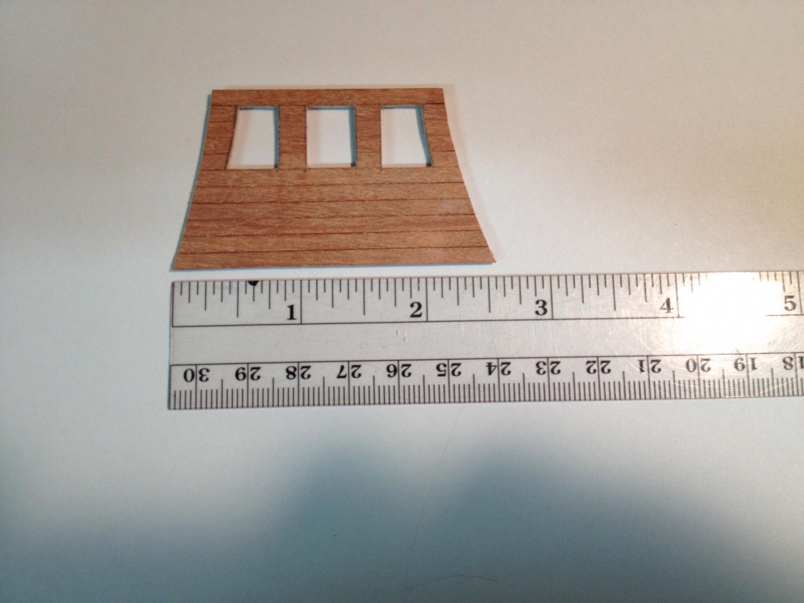
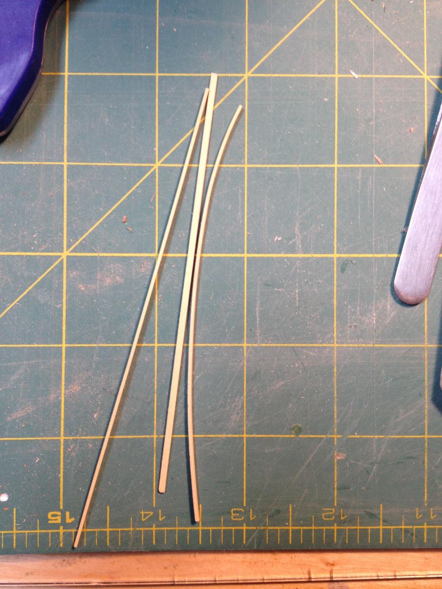
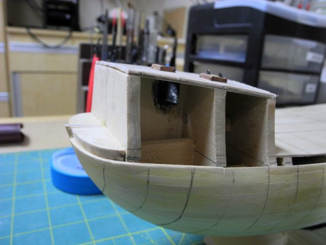
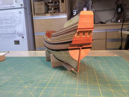
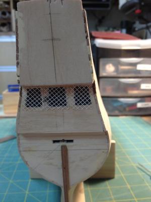
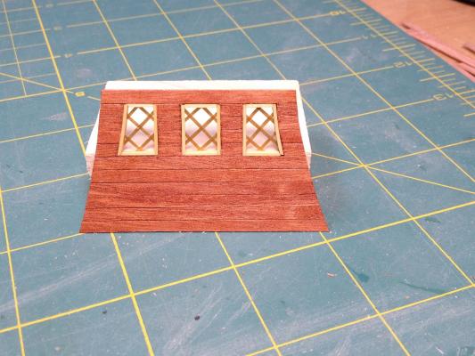
Paragon – a Modified Mayflower Part 6 – Counter and Stern Windows Before I could begin planking I needed to finish the stern planking and to build the stern windows. Unfortunately I didn’t take any photos of the planking that was done on the counter and the stern below the counter. The model has three stern windows – the outside edge of each of the two outboard windows follow the lines of the stern, as in the following photo taken before planking began. In this photo I had started to follow the kit’s instructions for constructing the windows, but was not happy with the results. Instead, I developed a different approach: First I cut a piece of 1/32 plywood to the shape of the middle section of the stern, with the shape of the windows cut out. Then I planked that section with 1/8 x 1/32 planks of African Pear. I needed to prepare moldings for around each of the windows, so I used some 1/16 x 1/16 boxwood strips. The strips that would be used for the outside edge of the windows were bent by soaking them in boiling water and then bending them over a hot planking iron. The final step was to use 1/16” gold pinstripe tape on an acetate back to make the window panes. When laying out the pinstripe tape I found that I could lay the tape in one direction with no problems, but when adding the tape in the reverse direction over the first layer, it made the first layer move and destroyed the symmetry of the grid. To avoid this, I sprayed the first layer with an artist’s matt fixative. After it was dried I applied the second layer and then sprayed that to secure the entire grid. The spray caused the windows to look like they had a pebbled finish, and I like the effect. When the windows were completed I glued them to the back side of the windows. After gluing this assembly to the stern and then finishing the stern planking (again, sorry – no photos) I was ready to start planking the hull.


-
I'm concerned about adding too much information to a build log, but I assume some readers might like to have more information on a particular subject. I use DropBox to store many of my files, and I will add links to a posting when I think it's appropriate. As an example, here's a link to a write-up on the tools I have: https://www.dropbox.com/s/oxm18m4s5b8syvu/TOOLS.docx?dl=0 I hope these links prove useful to some folks.
-
Using taper jig on Byrnes table saw
Mahuna replied to Landlubber Mike's topic in Modeling tools and Workshop Equipment
Thanks Greg. A visual explanation is always best. -
Hi Patrick After seeing your excellent work I really appreciate the compliment. I'm trying to post a section each evening until I catch up to the actual build (right now I'm working on the figurehead).
-
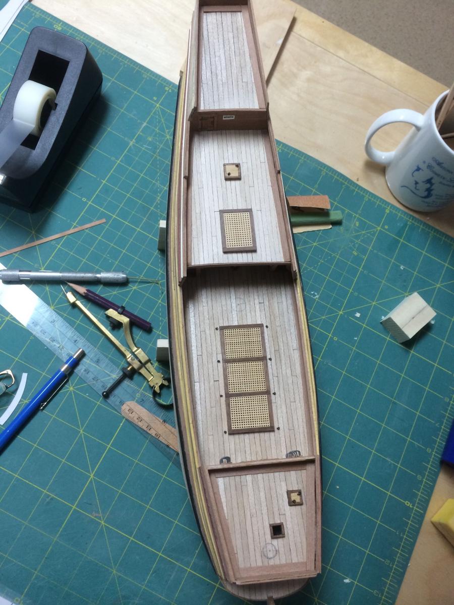
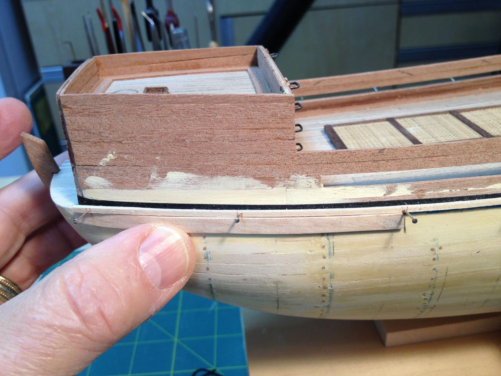
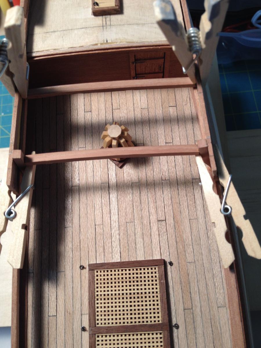
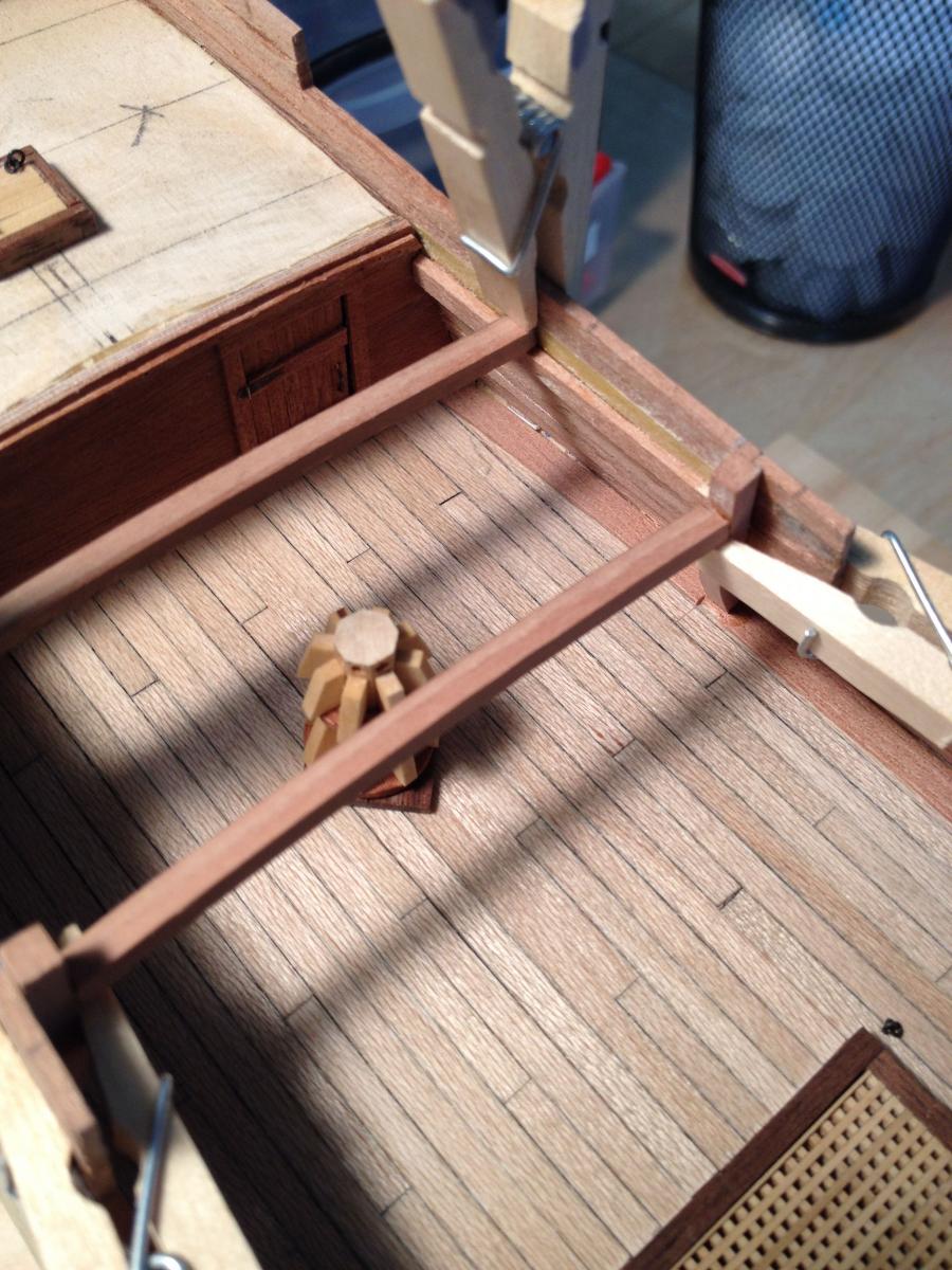
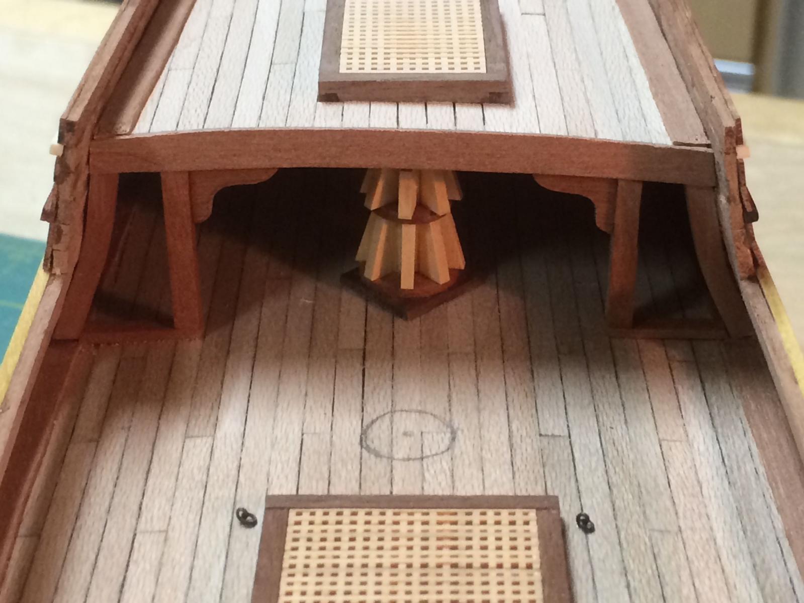
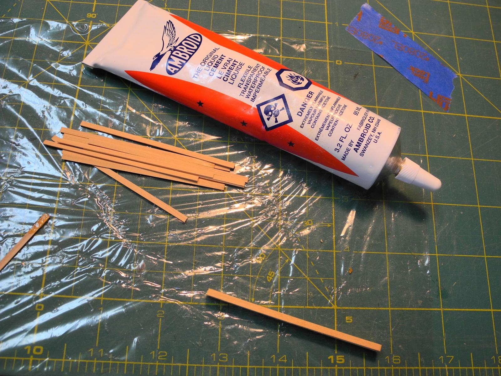
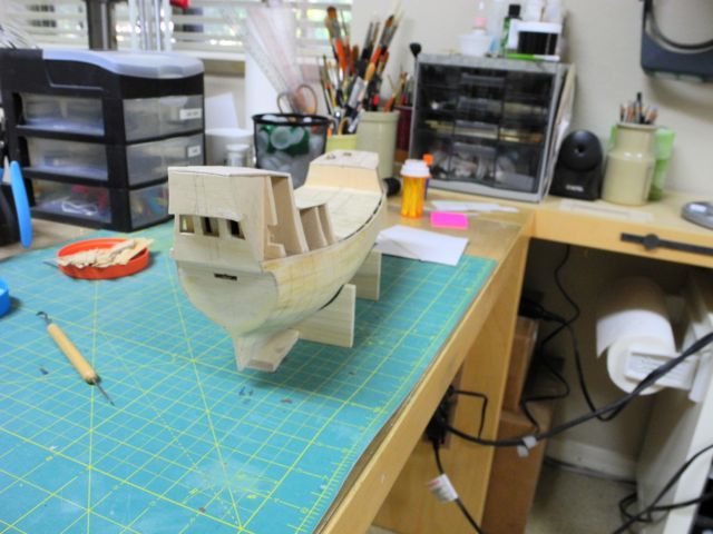
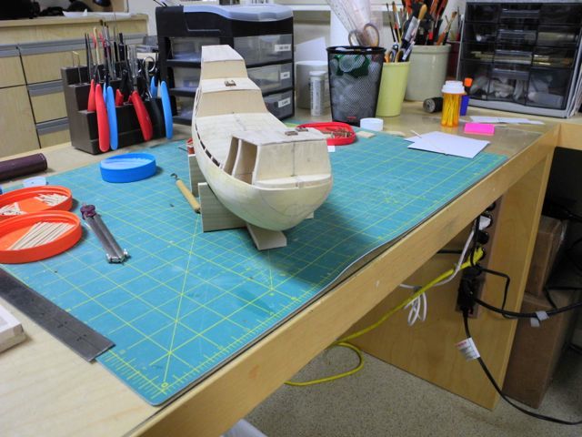
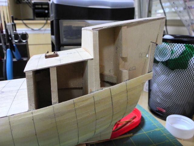
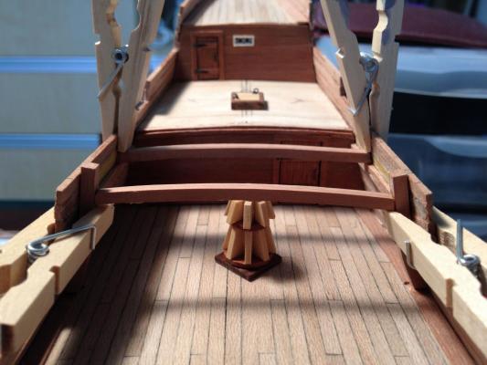
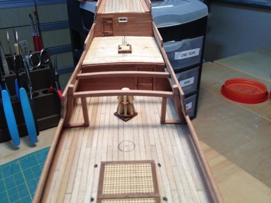
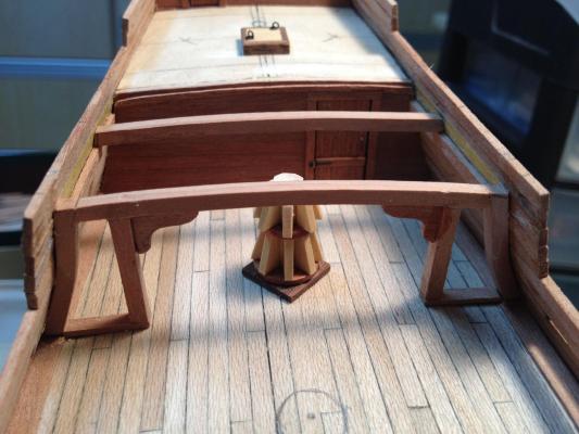
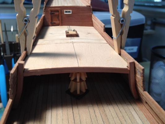
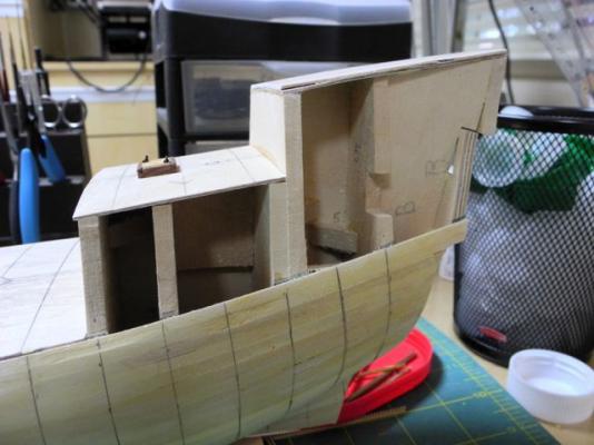
Paragon – a Modified Mayflower Part 5 – Planking Once the bulkheads and hatches were completed I could start the deck planking. I made the deck planks from sycamore, cut to 1/8 wide by 1/32 thick. I chose sycamore because the light grey color gave the impression of a weathered deck. I found a nice piece of sycamore in a Woodcraft store – the piece was originally intended as a turning blank and I liked the color and the grain. The deck planking was pretty straightforward, and I made sure to stagger the planks. The kit for the model provided some bulwark templates to provide the shape of the planking above the planksheer. I tried making duplicates of these templates from plans. I was not happy with the result, so I decided on a different approach for planking that area. The idea of the templates, which are 1/32” thick, is to give a solid surface to attach all exterior planks, and also to provide a surface for the planks which would be exposed inside the bulwarks. Since I was planning on using 1/32” thick planks, this would have provided bulwarks which were 3/32” thick. I decided to use 1/16” planks to form this part of the ship, and to use liberal amounts of wood filler to ensure the upper hull was properly shaped. Once this was done, exterior planking would all be at the same level. I was so focused on making this idea work that I didn’t take any photos of this work as it developed. The following photos were taken after the fact, when I was starting the exterior planking, but they show the results of this work. Here is where I made a major detour from the kit plans. The kit process is to complete the exterior planking before finishing the deck planking. On my build, the key was to finish the interior work – I wanted to make sure every thing I had built was sound before investing more time in the rest of the model. So, after I had built the bulwarks, I needed to complete the half-deck. Here again, I decided to deviate from the plans and instructions. The kit calls for building two partial walls to support the front of the half deck. I wanted to leave this area as open as possible, so I constructed a deck clamp to support an additional deck beam. (I constructed a jig to bend the deck beams to the proper camber, but here again I forgot to take photos – too focused on the work at hand). After installing the deck beams, I found that I needed to bend the vertical support on each side of the entrance to this area – which I accomplished using boiling water and then clamping the beams in place until they dried. It was then a simple matter to install another vertical beam to support the forward edge of the deck. And then I cut two knees for supporting the deck. Once again I used Ambroid glue to glue the two pieces of stock together and then shaped the knees. After separating the stock in an acetone bath I had two identical knees. About Ambroid and Acetone I know that many modelers are reluctant to use acetone, because of the potential side-effects of exposure to the fumes from acetone (and from Android, which I believe has some acetone as an ingredient). My feeling is that the dangers can be addressed simply by leaving an open container of acetone outdoors or by closing the container containing the acetone while it is dissolving the Ambroid glue. Also, while working with the Ambroid glue I wear nitril gloves, mainly to avoid messy cleanup. I may find out I’m wrong about 30 years from now, but oh well, if I’m still around at that time (100+ yrs old) it will be another lesson learned. After that construction it was a simple step to install the sub-deck. And then the planking and another grating. Lots of lesson learned - isn't that what we love about this hobby?


-
Thanks Mark. Yes, much simpler. That's typical of my learning process - I tend to overcomplicate things at first, then the light bulb eventually turns on.
-
Hi Bob: I'm looking forward to following another of your great builds.
- 127 replies
-
- 1
-
-
- dragon class
- yacht
- (and 1 more)
-
ancre La Salamandre by tadheus - 1:24
Mahuna replied to tadheus's topic in - Build logs for subjects built 1751 - 1800
Wonderful workmanship, Paul. I just discovered your build log and will be following along. -
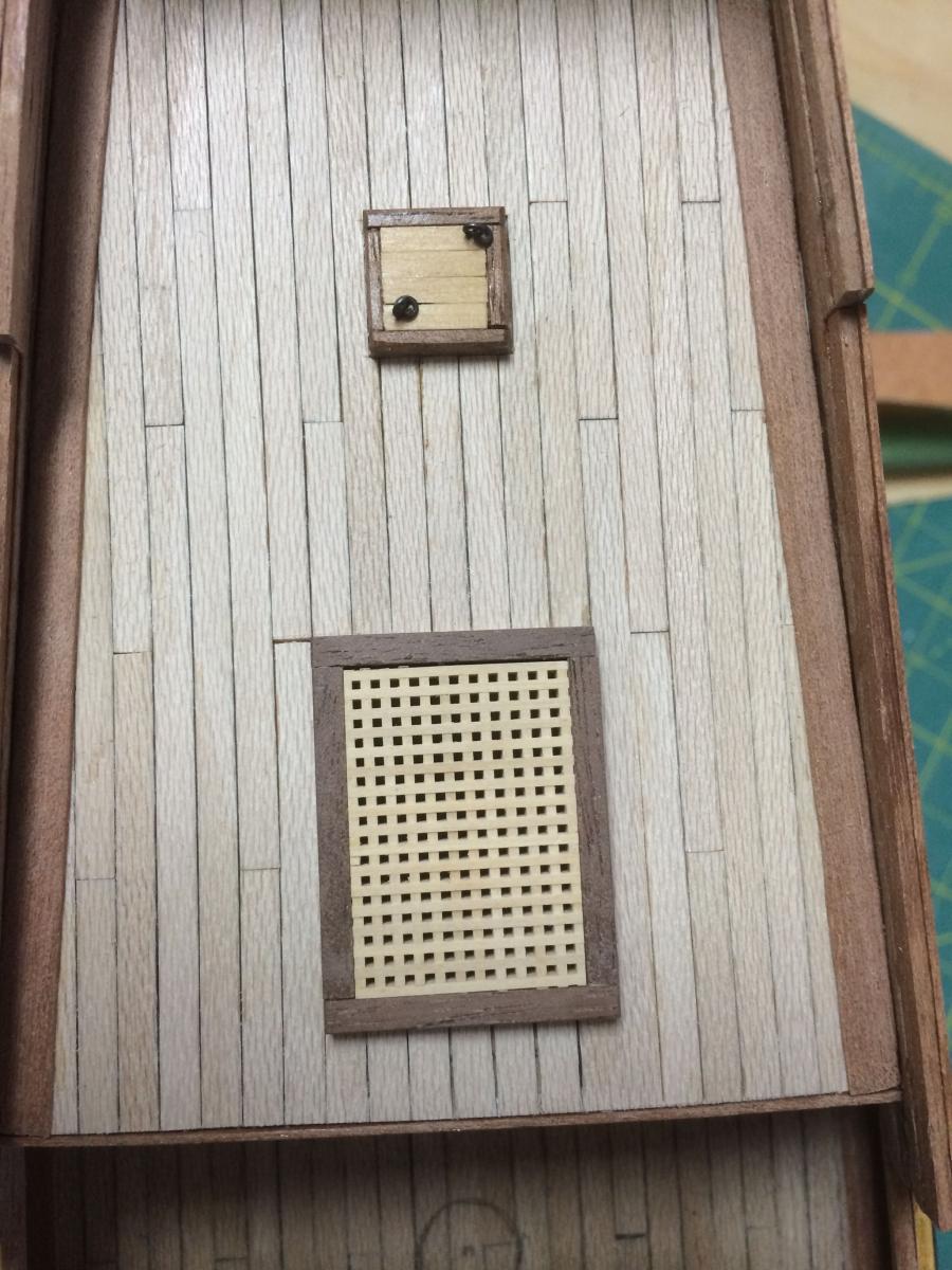
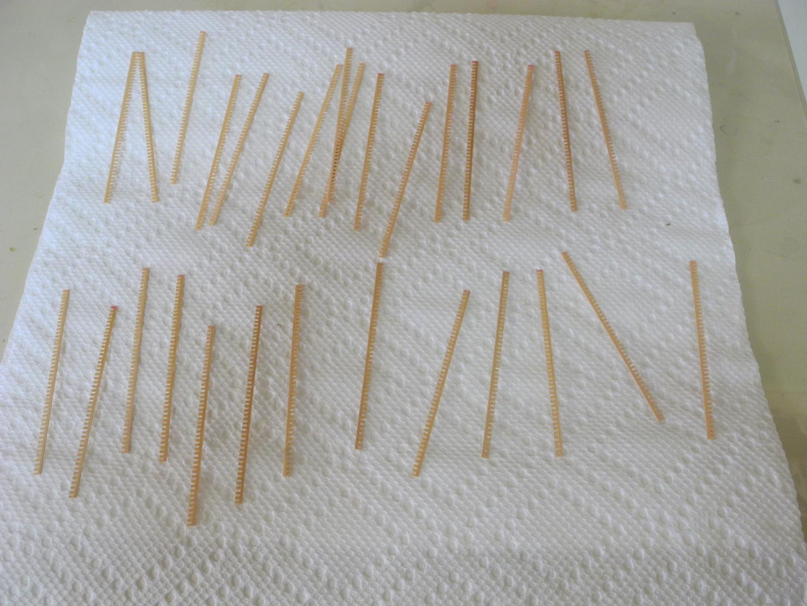
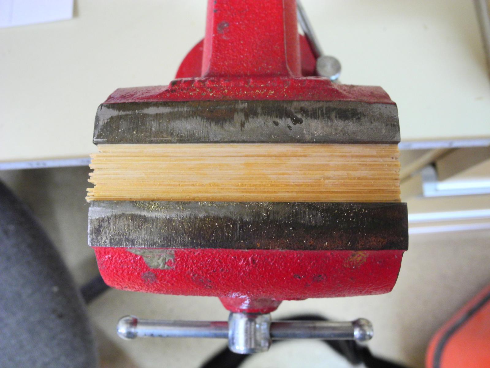
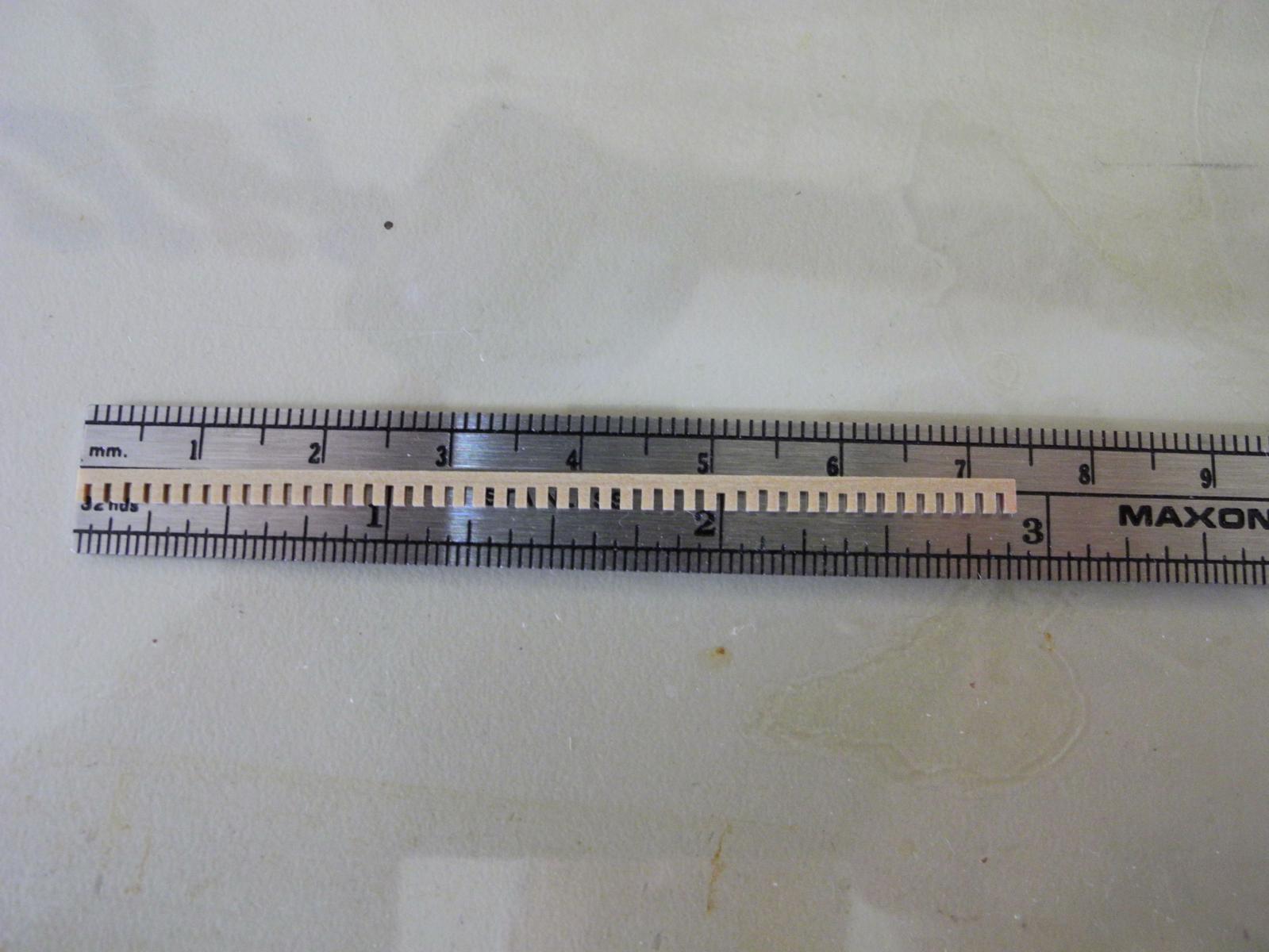
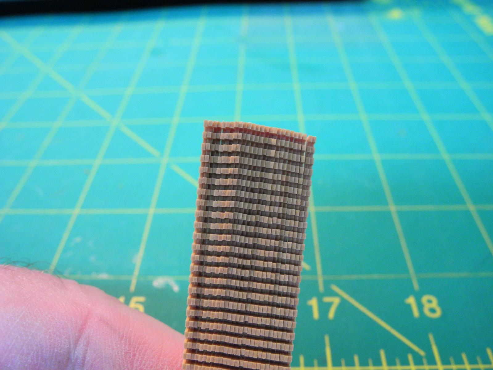
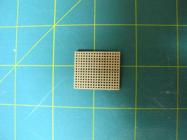
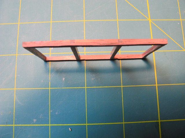
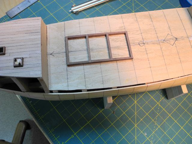
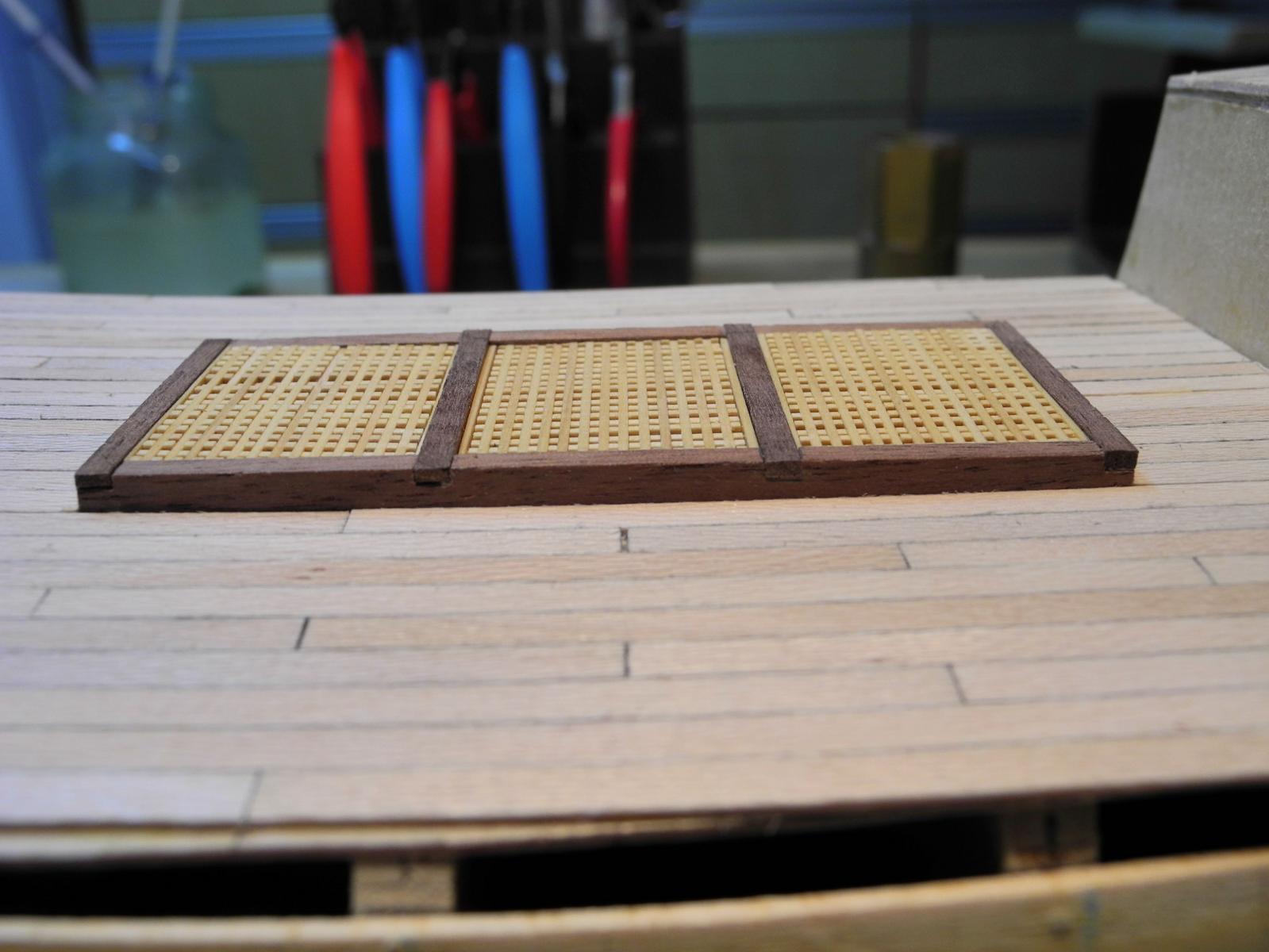
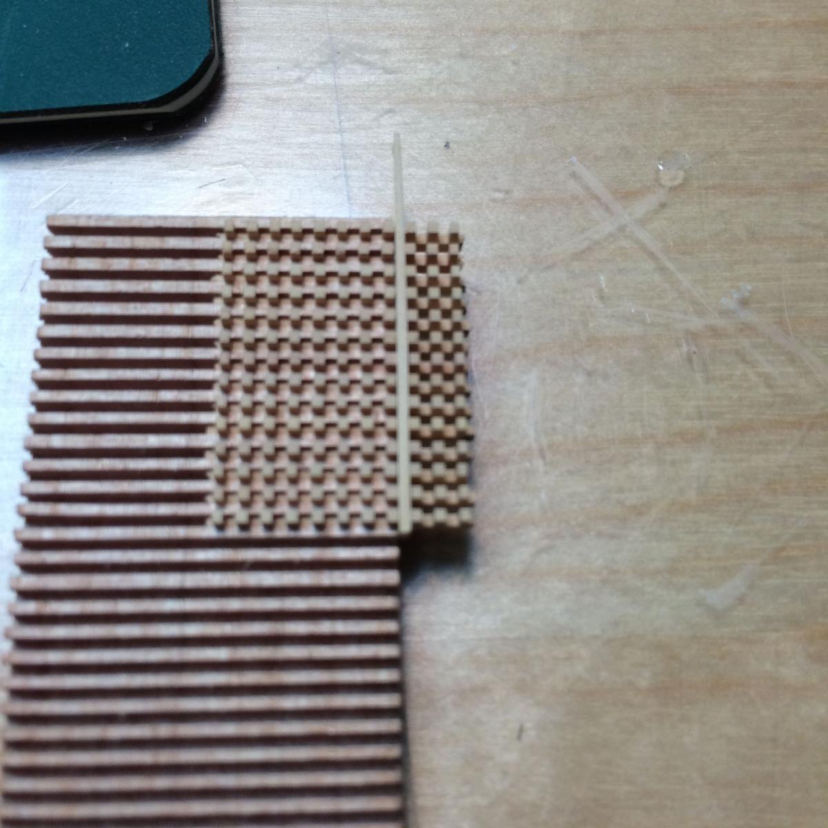
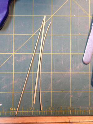
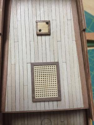
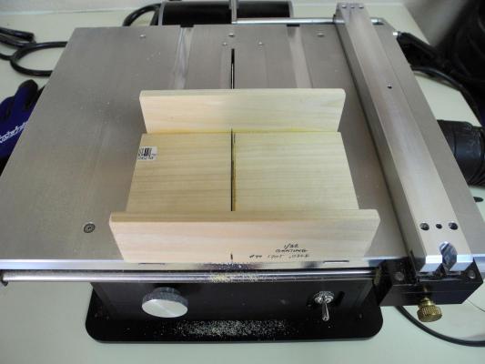
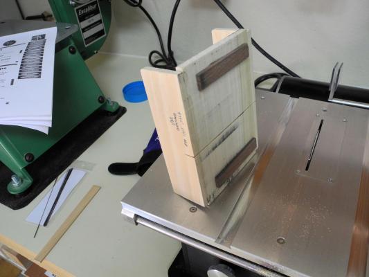
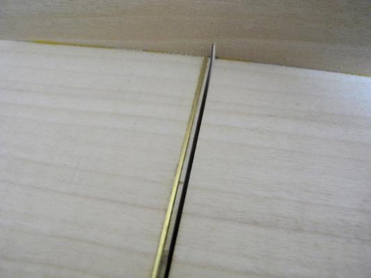
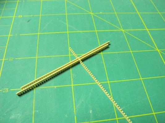
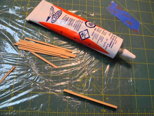
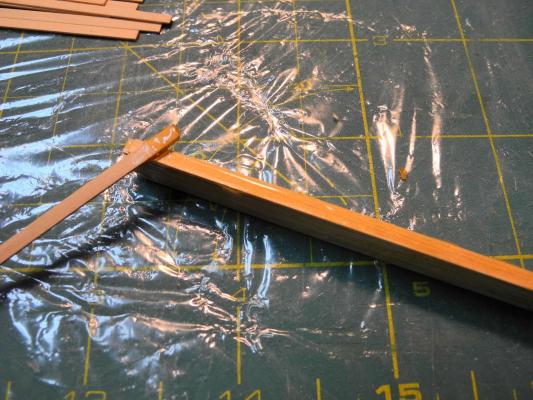
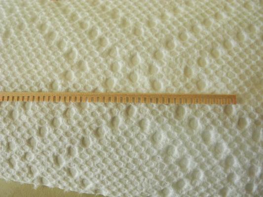
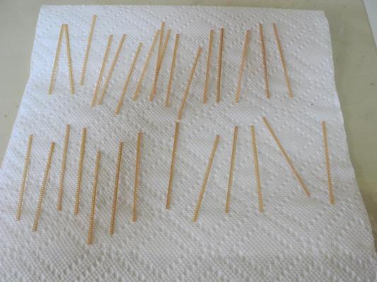
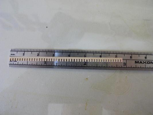
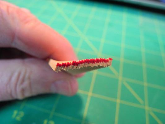
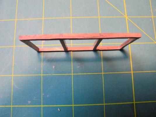
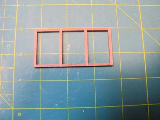
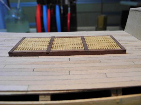
Paragon – a Modified Mayflower Part 4 – Gratings Next up was making gratings. To be accurate, the gratings needed to be small enough where the holes were no bigger than 1/32” square (this equates to about 3” square in actual size). I made up the typical ‘sled’ for the circular saw I then milled a small billet of boxwood to about 1/8 thick. I ran this through the jig to create the ‘teeth’ needed for interlocking the planks, but when I tried to cut it to individual pieces 1/32 thick the ‘teeth’ were destroyed by the cutting. I did some research and found an approach that worked for me: I milled individual planks 1/8 wide and 1/32 thick. Using Ambroid glue, I glued these planks in a stack and compressed them in my vise for a few hours. This made a ‘billet’, which I then ran through the the thickness sander to bring it to the required thickness, then through the saw using the ‘sled’. When all of the ‘teeth’ were cut I put the billet in a bath of acetone, which dissolved the Ambroid glue and produced individual planks ready for the grating. This solution was simple – to this point. I then needed to learn some new lessons before I could make acceptable gratings: 1. The individual planks need to keep the same alignment in the grating as they were when cut, otherwise the teeth will be slightly staggered and won’t line up properly. This will cause some broken teeth and will spoil the grating. In order to be sure of this, I started coloring one edge of the billet before sawing, so that after the planks are separated out they can still be properly stacked. 2. I found that I was sometimes not taking care that the billet was making full contact with the floor of the sled at every cut. This cause shallow cuts that caused inconsistent ‘teeth’ in the plank. This caused alignment problems when assembling the gratings. After much trial and error I was able to produce acceptable gratings and proceed with the build. This learning process took several weeks and consumed some pricey castello boxwood, but was a valuable experience. This is the frame for the main hatch. The final result looked pretty good to me. Much later I needed to make small gratings for the beakhead, and decided to use a somewhat different approach: I made a grating jig by running a billet through the sled. I cut the grating planks so that the teeth were a consistent 1/16’ long, then lined up the planks in the jig – tooth side up. I then was able to slide some small (1/16 x 1/32) battens into the grating to complete it. This approach was much simpler than my prior approach (matching the teeth of individual planks), and produced better results. Lots of lessons learned! Frank


-
Hi Peter: Thanks for looking in. And thanks for the compliment, but I still think your Druid is beyond anything I could manage right now. Maybe someday .... Interesting about John Howland - it's great that you're able to trace ancestry that far back. My father knew a lot of our family history going back to the 1700's, but unfortunately we lost the notes we had taken in discussions with him before we lost him. Frank
-
Great job Brian! I'm surprised you didn't need the follower at that length. You've already turned something much longer than I ever did on the 17" lathe - I'm sure you got tired of cranking after a while. It doesn't surprise me that you jumped right into it - now you'll be looking for anything you can use the new toy for. Frank
- 831 replies
-
- 1
-
-
- Armed Virginia Sloop
- Model Shipways
- (and 1 more)
-
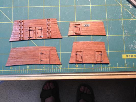
Paragon – a Modified Mayflower Part 3 – Inboard Bulkheads The various inboard Bulkheads needed to be built and installed before any deck or hull planking could be done, and these vertical walls themselves needed to be planked before installation. So the first order of business was to learn how to cut quality planks. The planks I would be using were to be 1/8 wide by 1/32 thick. Since I had never used a circular saw before, I needed to go very slowly and learn each step of the way. I had a lot of trouble at first, with inconsistent thickness of the planks (as much as a 1/64 difference from one end to the other). Jeff Hayes of Hobby Mill has posted some real good instructions on his web site, and these instructions helped me learn to cut more consistent planks. Once I started planking the bulkheads, there was still a noticeable difference in the thickness of adjoining planks, probably due to the small scale where even a minor difference is noticeable once the planks are laid side-by-side. I overcame this by cutting all my planks a little thicker than they need to be, then running them through my thickness sander until they’re all a uniform thickness. Lesson learned: I always finish milling planks by running the entire batch through the thickness sander. I made a few minor modifications to the bulkheads: The instructions called for using 1/8” wide planking for the doors, which I thought looked a little big, so I used 1/16’ wide planks instead. I also added door frames and horizontal planks where the hinges were to be attached. The plans also called for wooden ladders to be added to the wall of the Forward Cubbridge Head, but I decided to change this to ‘iron’ rungs made out of 28 gauge wire. The hinges were made from very thin copper sheeting (I don’t remember the gauge) which was blackened using liver of sulphur. I doubled a piece of the sheeting and cut out a pair of hinges at a time to try to get them the same size. Here’s a photo of the finished bulkheads. The little window in the poop bulkhead is framed in 1/16 holly. Frank
-
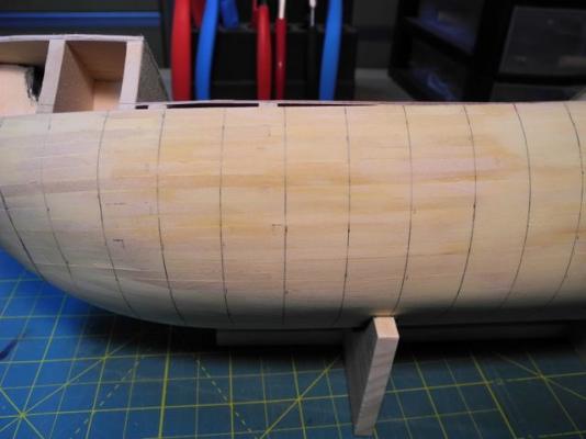
Paragon – a Modified Mayflower Part 2 – GETTING STARTED I decided to use 3/16 plywood for the former and 3/16 basswood for the bulkheads. I started by making multiple copies of the bulkheads and former from the plans. I tried several ways to stick these drawings to the plywood and basswood that I’d be using. Elmer’s rubber cement did a fairly good job of sticking the images to the wood, but was very messy and difficult to remove from the wood after the cutting. My wife, a quilter, suggested using freezer paper – making it adhere to the wood by pressing it with a warm iron (freezer paper is known as a quilter’s best friend). This worked well once I figured out the correct temperature, but the paper lost its adhesion if the wood was not cut out within the first day or so. Ed Tosti uses an ordinary glue stick for adhering plans to wood and I tried it – perfect! No reason to use anything else. I’ve learned that anything EdT recommends is probably the best way to accomplish a task. His work is superb, and his explanations make seemingly difficult tasks easy to understand. Next came cutting the bulkheads and the former, and once again I tried some different approaches. I first tried doing this with hand tools by using a coping saw or a jewelers saw, and found the process really tedious and prone to error. I wound up leaving a lot of waste, which need to be sanded or filed by hand. I have an excellent old Rockwell 14” bandsaw, so I tried using a 1/8 inch blade on it and this worked better. It still required a lot of cleanup afterwards, but I probably would have stayed with this approach if I hadn’t found a great buy on an Excalibur scroll saw. This made cutting the bulkheads a breeze, with only a little cleanup required afterwards. I don’t have a lot of photos of installing the bulkheads and fairing for Paragon, but this is common to all builds and I’ve learned a lot of very helpful techniques on MSW. I made sure that each bulkhead was square to the former by using small engineer squares, then I glued small pieces of scrap wood cut at a 90 degree angle in each corner formed by a bulkhead and the former – 4 pieces for each bulkhead – to hold them square while the glue dried. When all of the bulkheads were installed and the glue was set, I installed a fitted piece of scrap wood between each pair of bulkheads, on each side of the former. These pieces were installed as close to the outside edge of a bulkhead as possible so they would tie the entire frame together and provide strength to the entire assembly. Next came fairing the hull, using several battens to ensure fair and smooth lines. I own a high-quality Gesswein rotary tool from my bird carving days, and I used this to fair the bulkheads, using sanding drums and a stump cutter. This is a very aggressive cutter, and needs to be used with extreme care. It will take off a lot of wood (and/or flesh) in a hurry if you’re not careful. Finally I installed the false decks cut out of 1/32 plywood. Next up was the first layer of planking. Following the instructions, I cut 1/8 x 1/16 strips of basswood on the bandsaw and used fairly long planks. I didn’t try spiling, since the plank dimensions didn’t allow it. Consequently I had lots of twisting at the bluff bow, and needed to do a lot of sanding and filling with wood putty. I used CA glue to hold the planks so that I didn’t need to worry about clamping. After I had completed the first planking, however, I started to worry about the CA glue failing and causing the model to deteriorate. To strengthen the model I made bamboo treenails and used one to secure each plank to each bulkhead. Each treenail was dipped in PVA wood glue. After the glue set I filed or sanded each treenail to be flush with the hull. Lesson learned: I’m going to use PVA and clamps for any future plank installations. The following photos show the hull lined off for the treenails. Frank


-
Thanks Brian - lots of lesson learned from this build. Frank
-
Hi Brian I enjoyed seeing your AVS today - as usual. It looks great in pictures, but even better in real life. You definitely have the talent and the eye. I'll keep working on you to dive into the scratch-building pool. Frank
- 831 replies
-
- 1
-
-
- Armed Virginia Sloop
- Model Shipways
- (and 1 more)
-
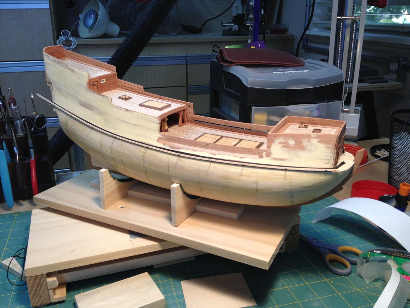
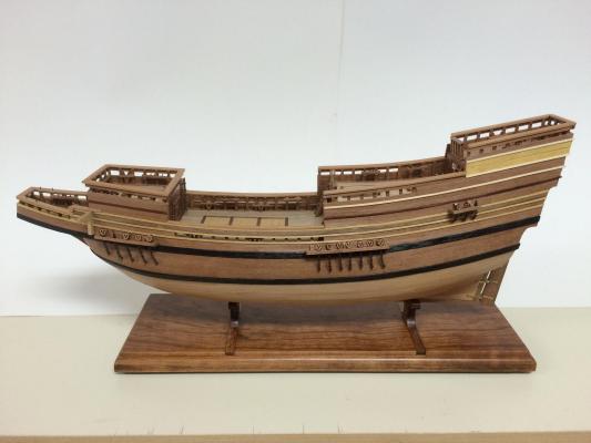
Paragon – a Modified Mayflower Part 1 - INTRODUCTION I started ship modeling in early 2012, and after I finished a couple of kits during that year, my wife half-jokingly said to me that as long as I’m building ship models, I should build “Paragon, the Mad Ship”. This was a character in a series of fantasy novels that we both enjoyed, called the ‘Liveship Traders’, by the author Robin Hobb. The theme of the series is that merchant ships were built of a special wood called ‘wizardwood’, and that after a time the figurehead would come alive and have its own personality. Paragon was a Liveship with a figurehead in the shape of a man. Paragon had been mistreated by its owner and consequently developed a negative outlook and a pretty nasty disposition. In fact, he had turned on his owners and crew, and legend was that he had killed them all. The townspeople called him the Mad Ship, and shunned him. This picture is from the jacket of the book. There were no detailed descriptions of the Liveships in the series of books other than descriptions of the figureheads, since these were personalities within the story. The descriptions of clothing, houses, modes of transportation, and weapons, gave the impression that the period was similar to western civilization in the 1500 – 1600’s. There were no firearms mentioned in the stories, so the ships did not carry cannons. Paragon, and all of the Liveships, were merchant sailing ships that generally gave the impression of ships from the era of explorers. I decided that this would be my first scratch build, but I felt that I needed a good set of plans and building instructions, so I looked for a kit that would be a good base of this fictional ship. I was able to buy plans for the Mayflower, from Model Shipways. The instructions for the kit are available as a free download PDF written by Chuck Passaro, the author of the Phantom instructions that I had already used. Chuck designed the Mayflower kit, and his practicums and instructions are clearly written and present a logical building sequence. The kit model calls for quite a bit of painting, but I decided to ‘paint with wood’ – choosing different woods to show the different colors in the ship. I’ve been working on the ‘Paragon’ since mid-2013, and it’s almost ready for rigging. I’ve been recording my progress along the way, so I thought I’d start this build log to show how I built the ship, and especially to discuss the many mistakes and lessons learned. Much of the building was trial and error (in some cases too many errors and do-overs!) and I hope this log will help others that are thinking of doing their first scratch build. There are some steps that didn’t get captured in photos (I was too busy muddling my way through and forgot the camera). Most of the photography was done with my iPhone, so please excuse some of the poor photo work. Here’s a photo of the current state of the Paragon. I was able to find most of the wood I would use through shopping at local woodcraft and wood supply stores. I decided to use African Pear and Madrone for the hull planking, bulkhead planking, and some visible construction elements. Castello Boxwood would be used for some pieces of ‘deck furniture’ - gratings, knees, capstan, etc. Walnut is used for some deck furniture and moldings. Other moldings were from Holly, Yellowheart, and Bloodwood. I used Sycamore for deck planking. The ship has a couple of black wales, but I didn’t want to mess with Ebony so I used Chimken and stained it to look like Ebony. Since this build is a fictional ship, I’ve been able to use some ‘poetic license’. The ship doesn’t have cannons, so I could skip that part. Since the figurehead will be a prominent part of the ship I needed to redesign the beakhead. I’ll be adding some fancy work to give it a ‘mystical’ appeal, but I’m leaving that until the end.

-
Hi Brian If you glue in the rod with epoxy before you start shaping you could hold the cleat by the rod - might make the shaping work go a little faster. Hope you can make the next meeting on 6/20 - can't wait to see your progress in person. Frank
- 831 replies
-
- 1
-
-
- Armed Virginia Sloop
- Model Shipways
- (and 1 more)
-
Rookie needs help!
Mahuna replied to twebb's topic in CAD and 3D Modelling/Drafting Plans with Software
Sun Lakes is the southern part of Chandler - if you remember Riggs Rd off I-10, it's right off that. I used to go through Greenville for work - flew in (from New Jersey) and drove down to Anderson. So you've lived in Biloxi, Greenville, and Tucson - and now you're in Australia! Sounds like some good stories there!