Mahuna
-
Posts
1,504 -
Joined
-
Last visited
Content Type
Profiles
Forums
Gallery
Events
Everything posted by Mahuna
-
 Bob - thanks for the kind wishes. The problems are stenosis-related, which are keeping me out of the modeling chair for a while. Patrick - a very interesting question. I had played with carving a sea serpent or dragon to sit beside the ship, but haven't decided what, if anything, to do for the display. I guess we'll wait and see how she looks when she's done and the figurehead is in place. Right now my feeling is to just get it done and move on to my next build, but maybe once I start working on the next one I'll fiddle with final touches on the display of Paragon.
 -
Hi Brian: Very good point on opening the holes of the blocks with an appropriate sized drill. I do this before rigging each block, before the block goes on the ship.
- 831 replies
-
- 5
-

-
- Armed Virginia Sloop
- Model Shipways
- (and 1 more)
-
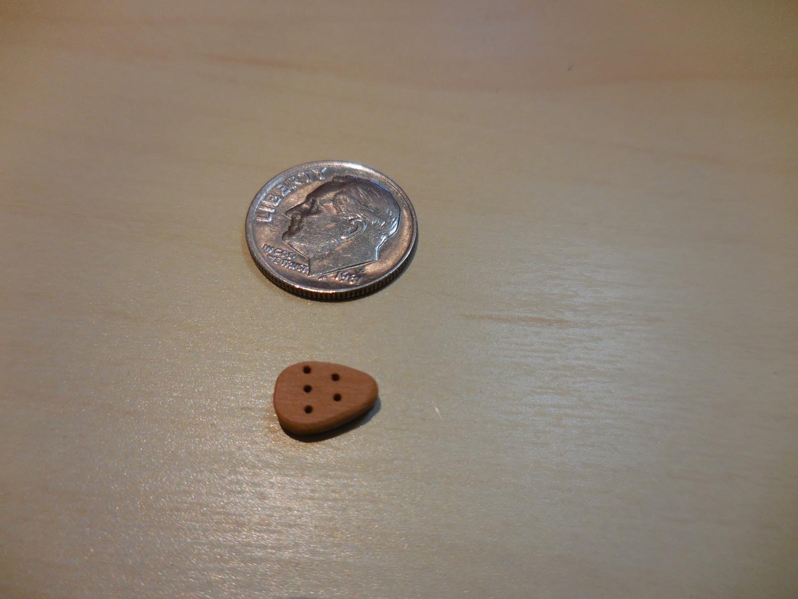
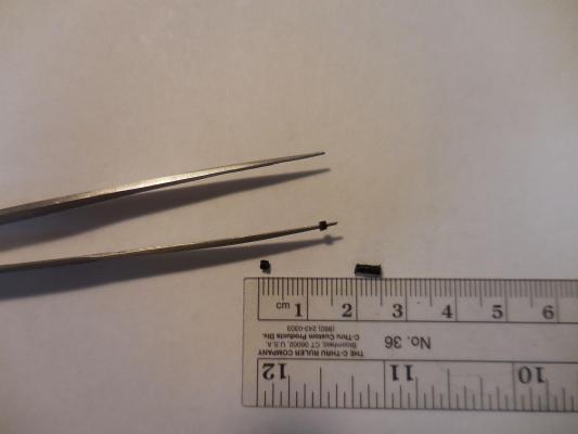
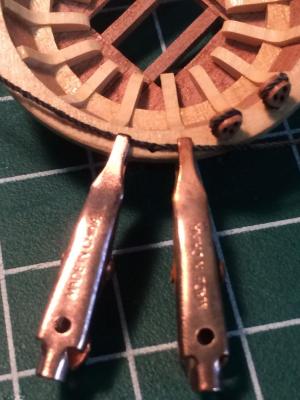
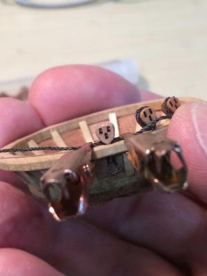
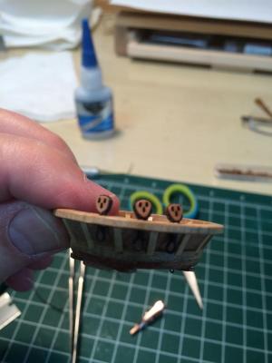
Ron - I knew this model was pretty small, being at 1:64, but the photo of the skipjack with the tools brings home how tiny it is. I've started the research on the Kathryn. I plan to build as much of the interior fittings as possible, and will use a much larger scale - I'm debating between 1:24 and 1:32. I'll be back east in October and hope to see the Kathryn for real and get some photos and measurements.
-
Thanks all for the comments and likes. Brian - there are a few little tricks (and limitations) I've learned. Let's talk about them when we get together next. Patrick - these are nothing compared to your little beds, settees, folding chairs, etc! Mark - I'm afraid you're right. I wasn't sure about that when I made them, but after they were completed I realized they wouldn't work in real life. I decided to leave them because they look ok. Another lesson learned - I need to do more research before making something that's new to me.
-
Very nice and very precise. Please show us your jig. You're getting closer to the world of scratch building all the time.
- 831 replies
-
- 5
-
-
- Armed Virginia Sloop
- Model Shipways
- (and 1 more)
-
Hi Patrick The whole boat is awesome. I can't believe you've reached this point in only a few months - it seems like I've been on Paragon forever.
-
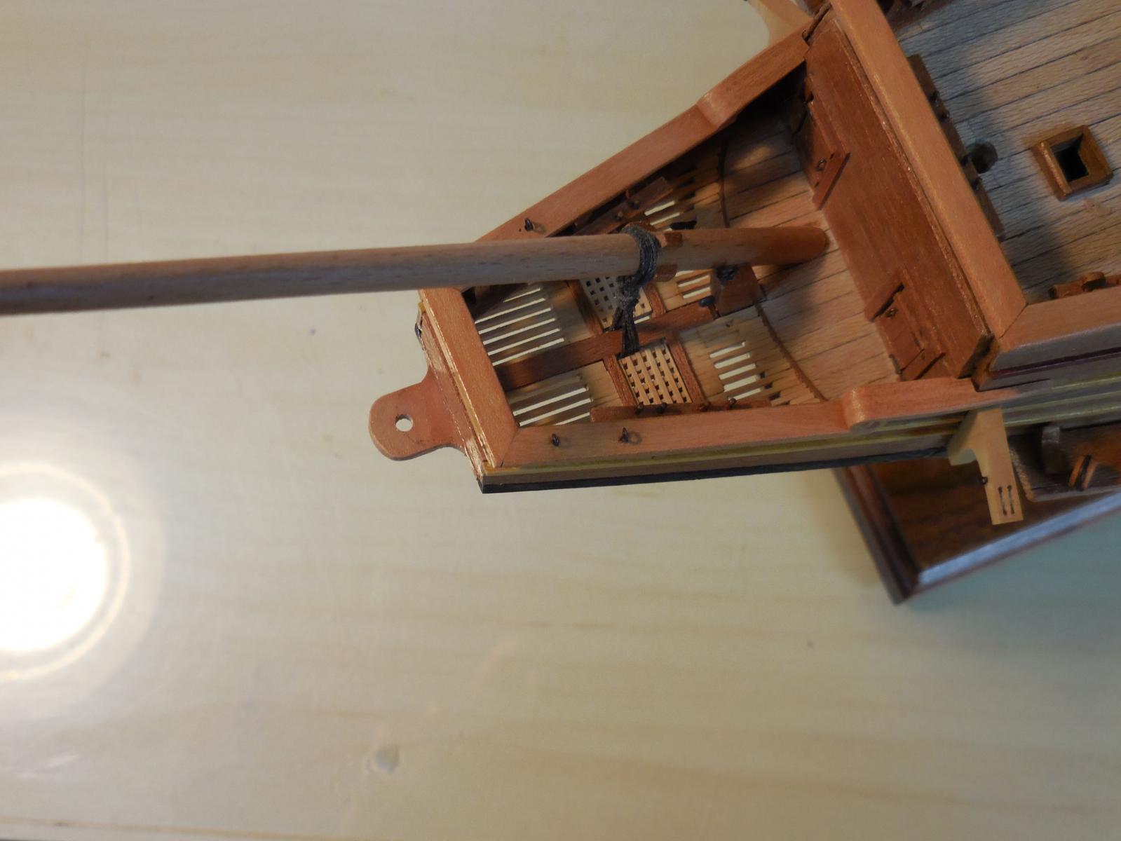
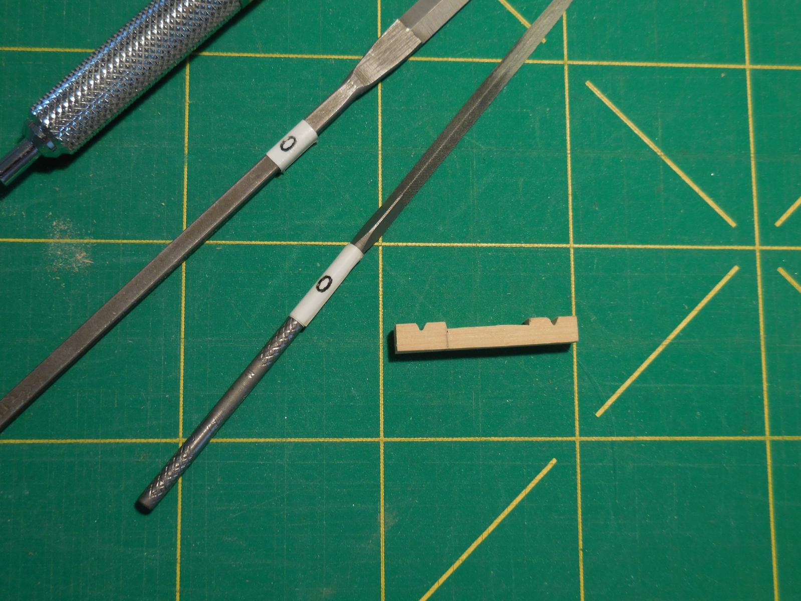
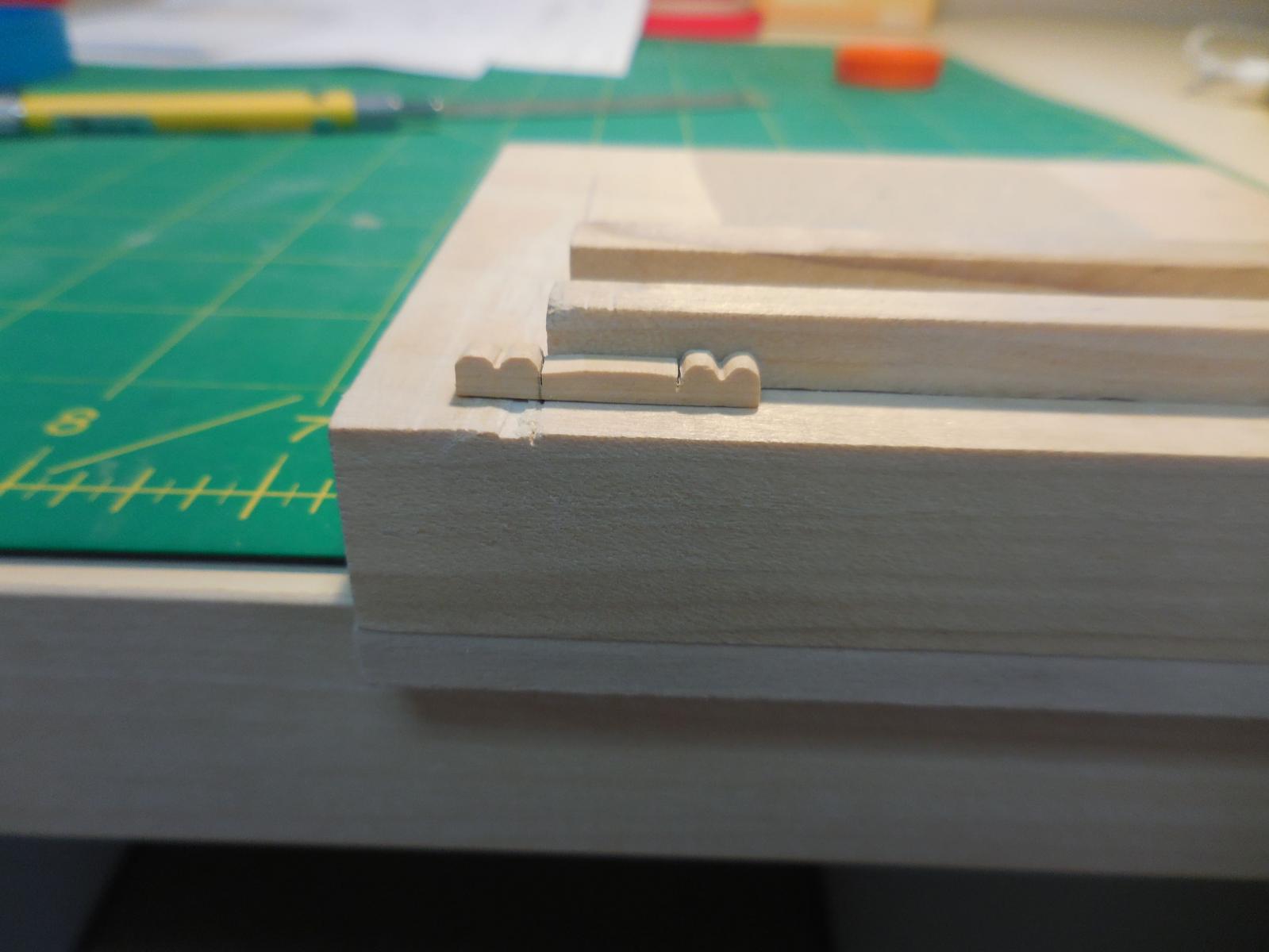
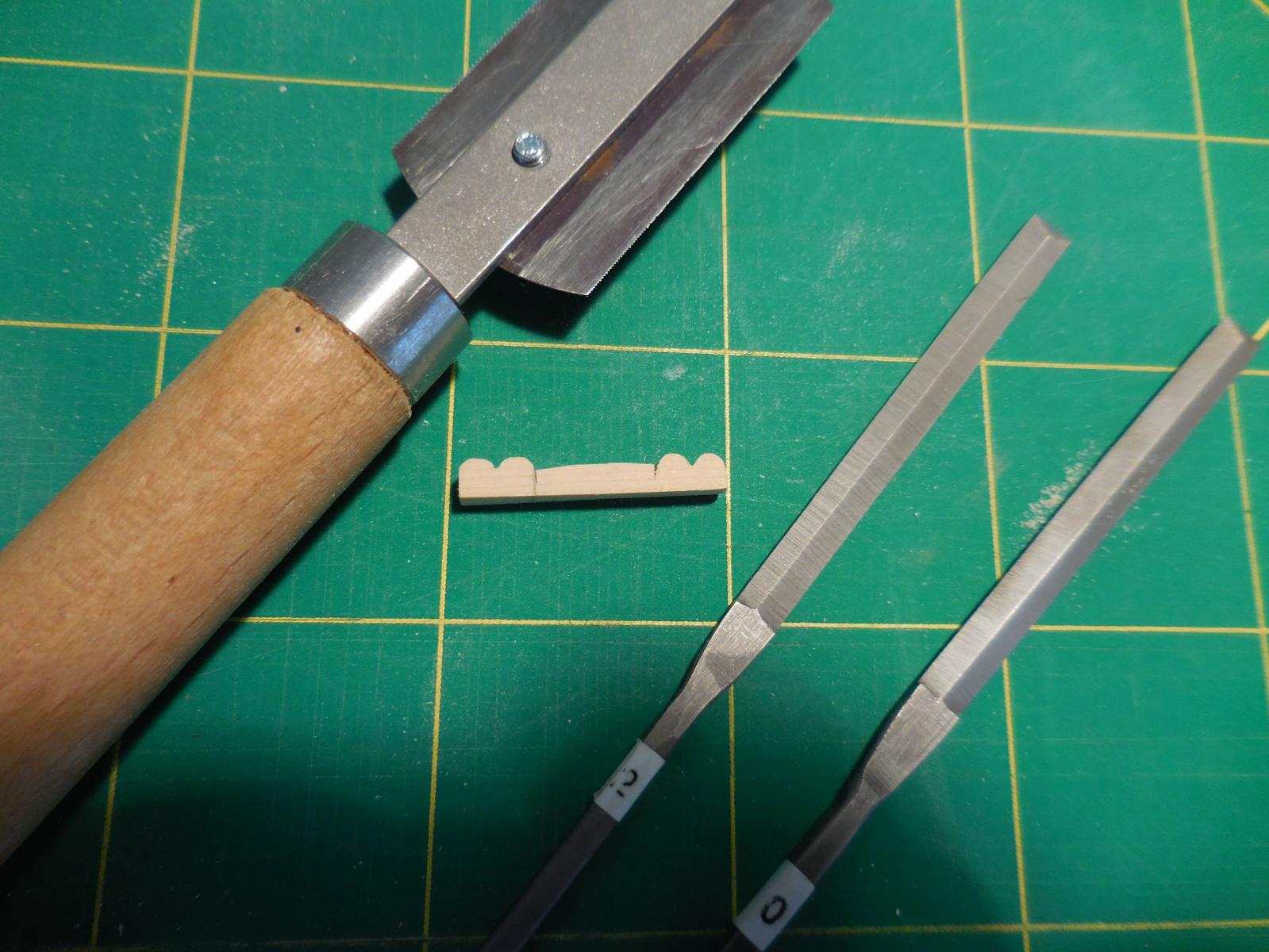
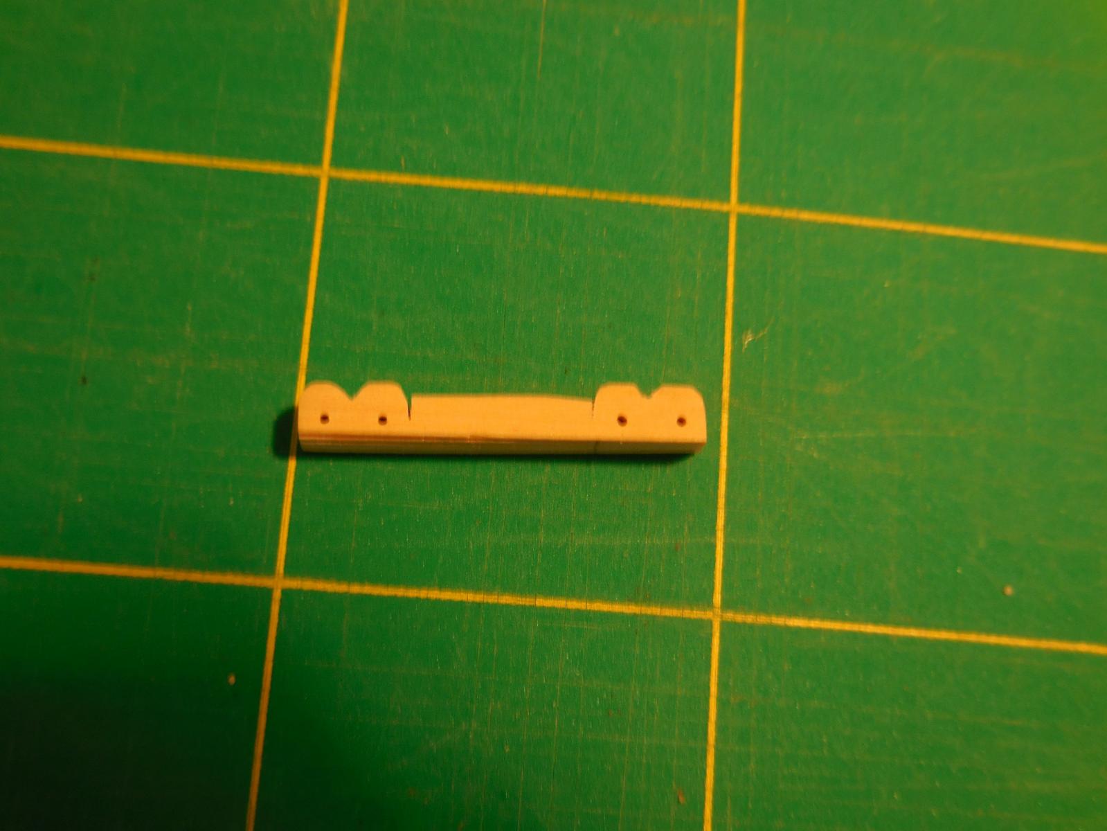
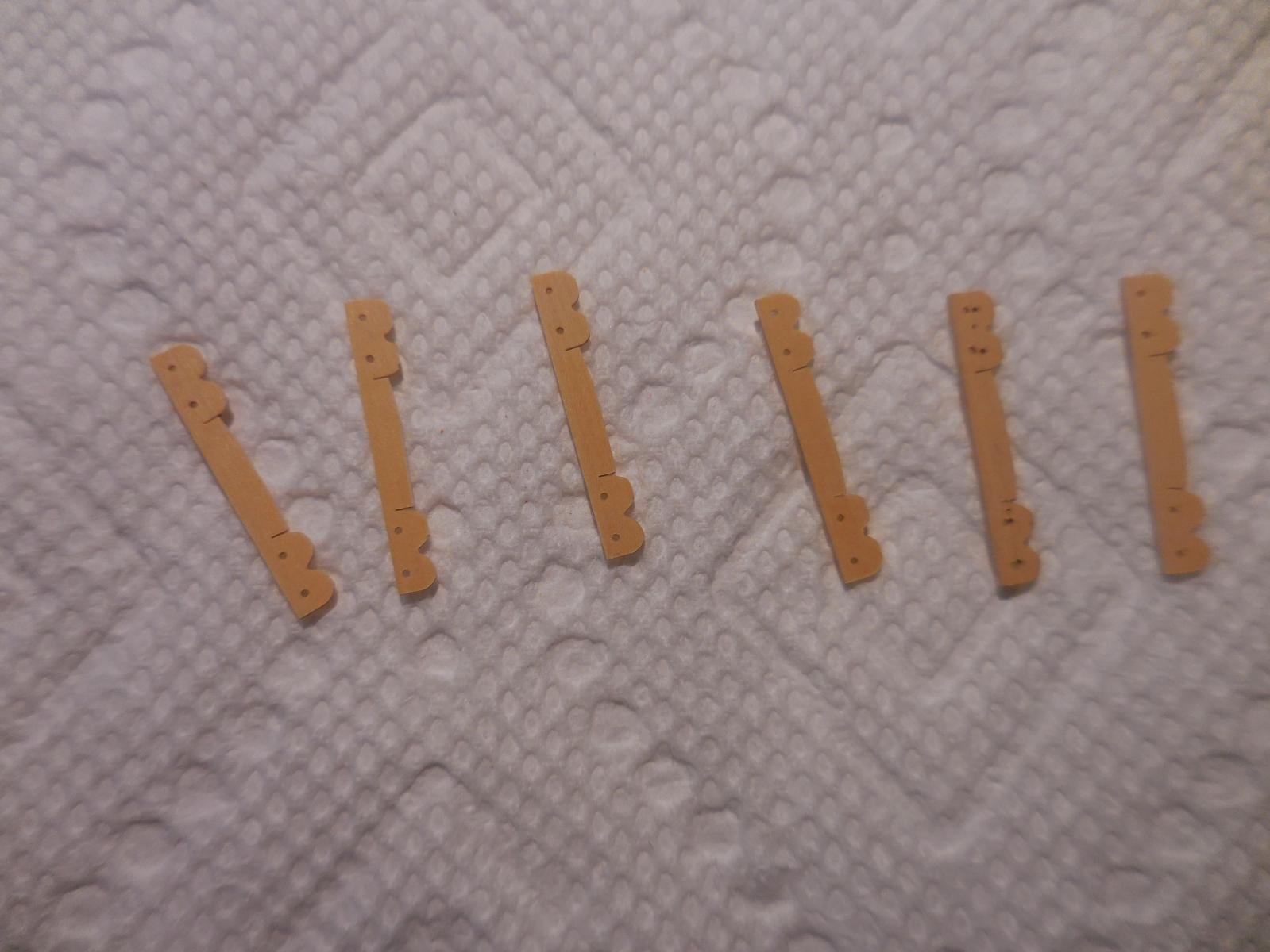
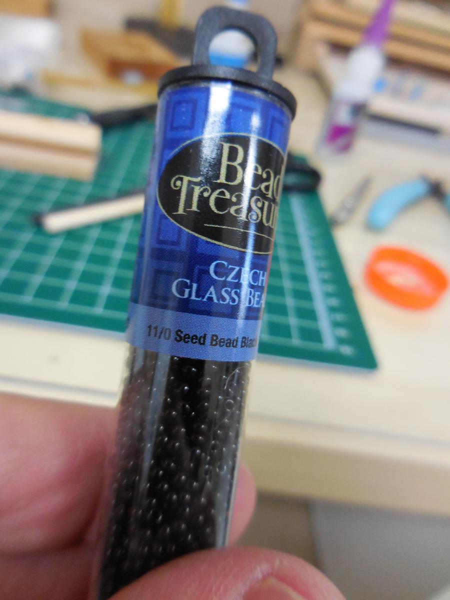
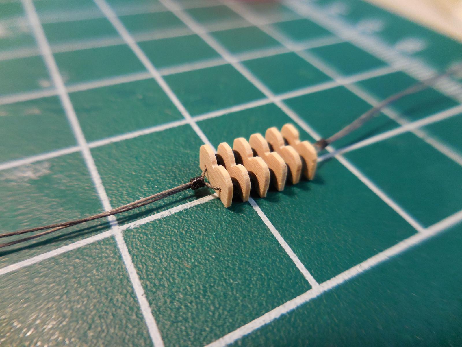
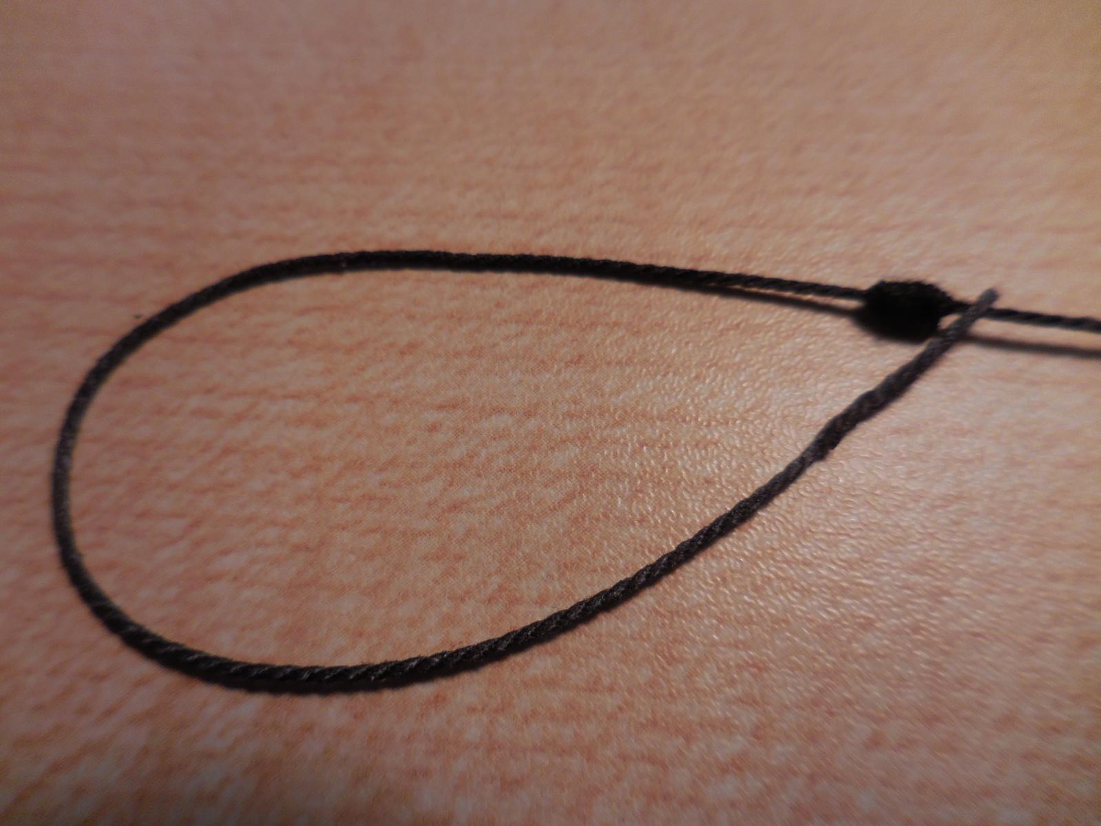
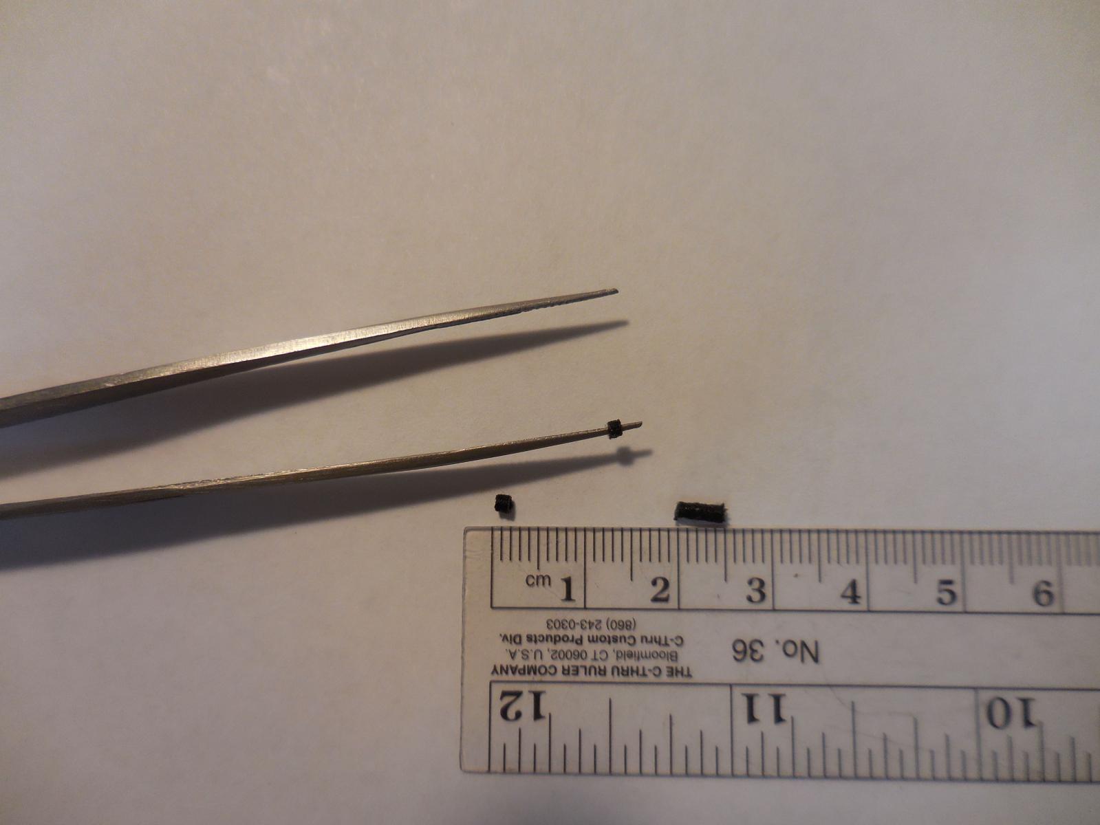
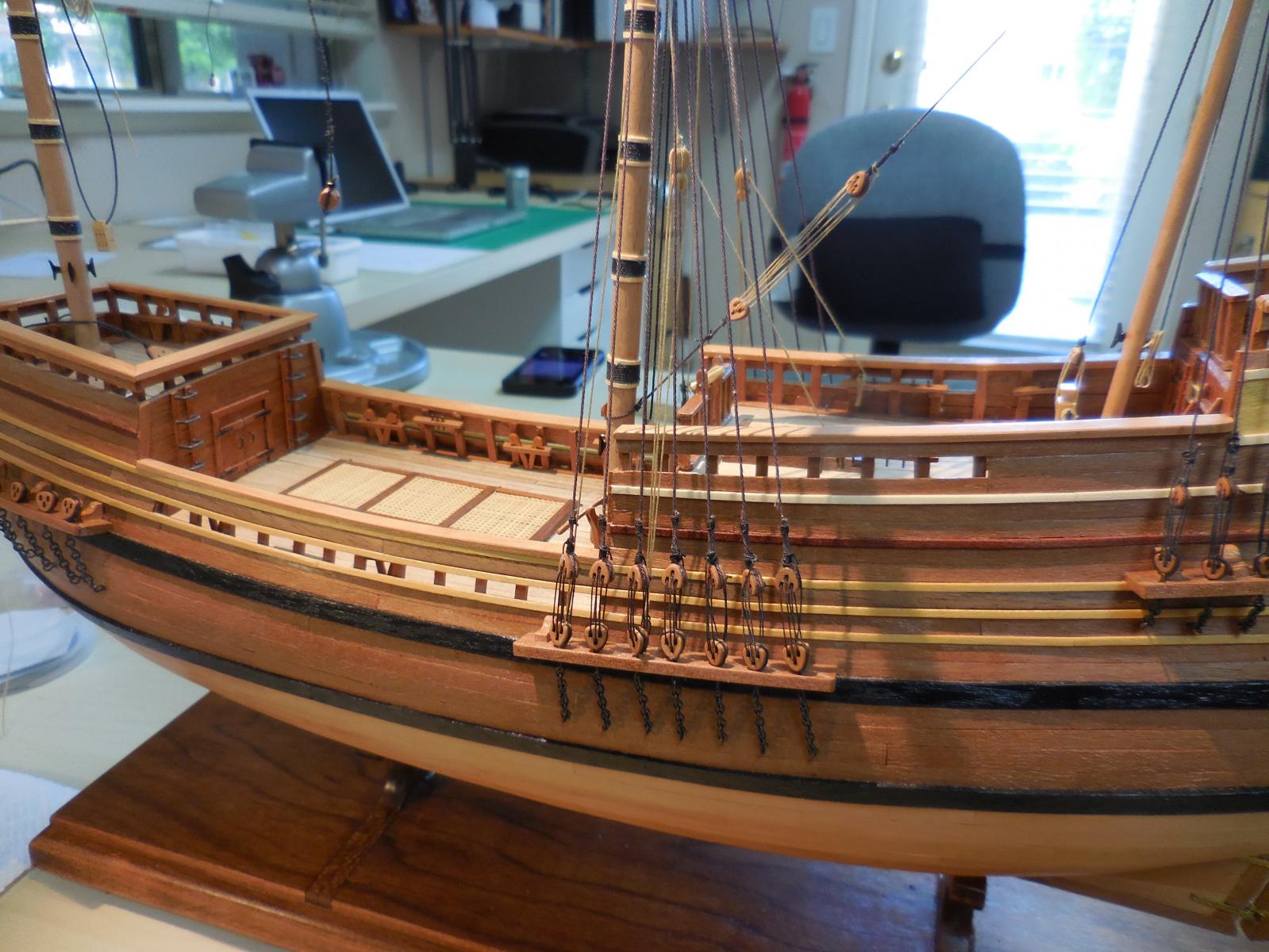
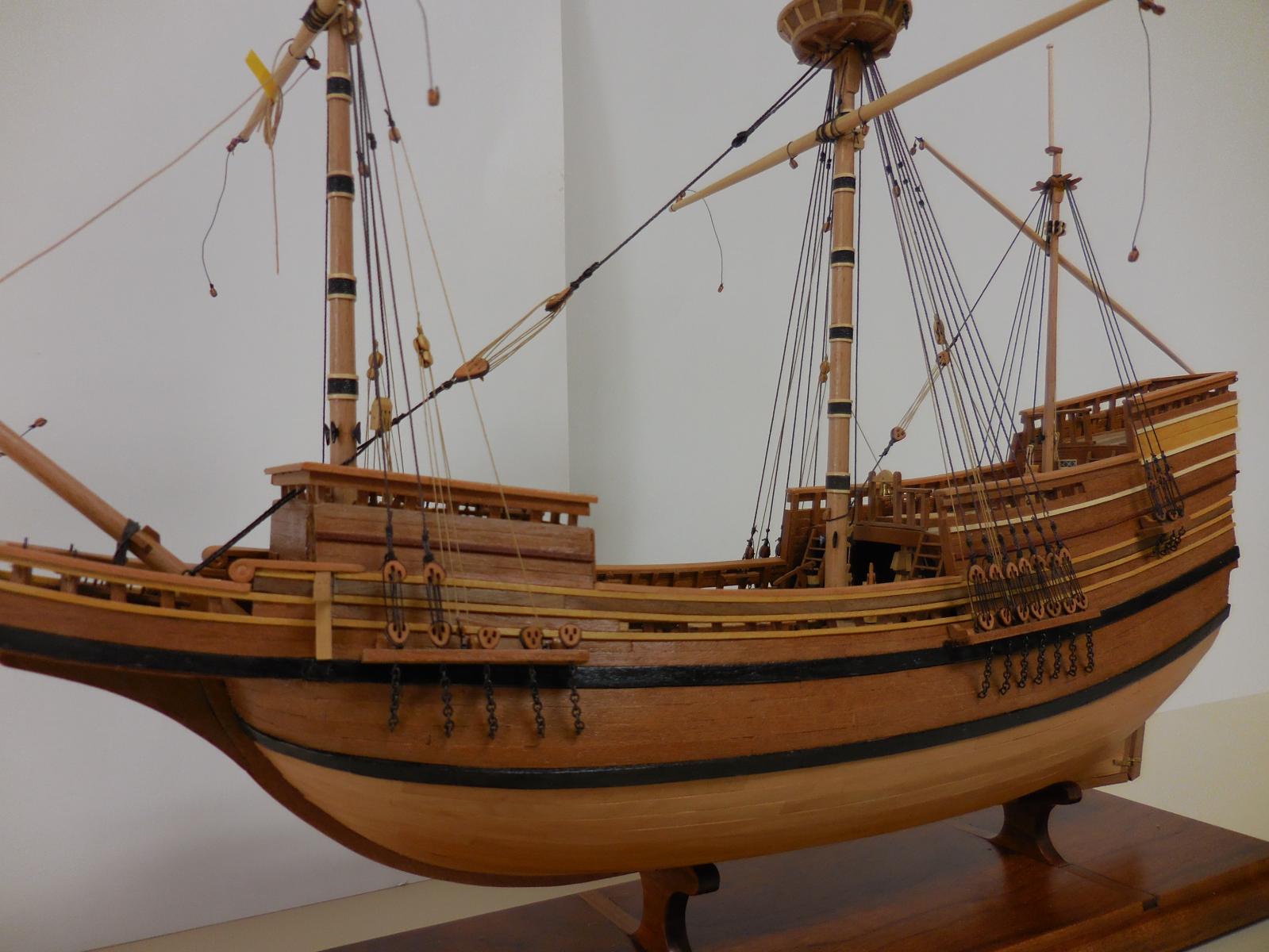
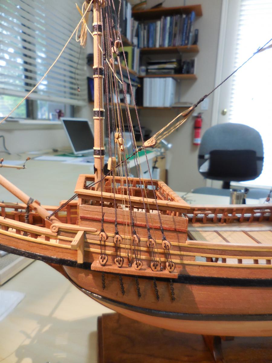
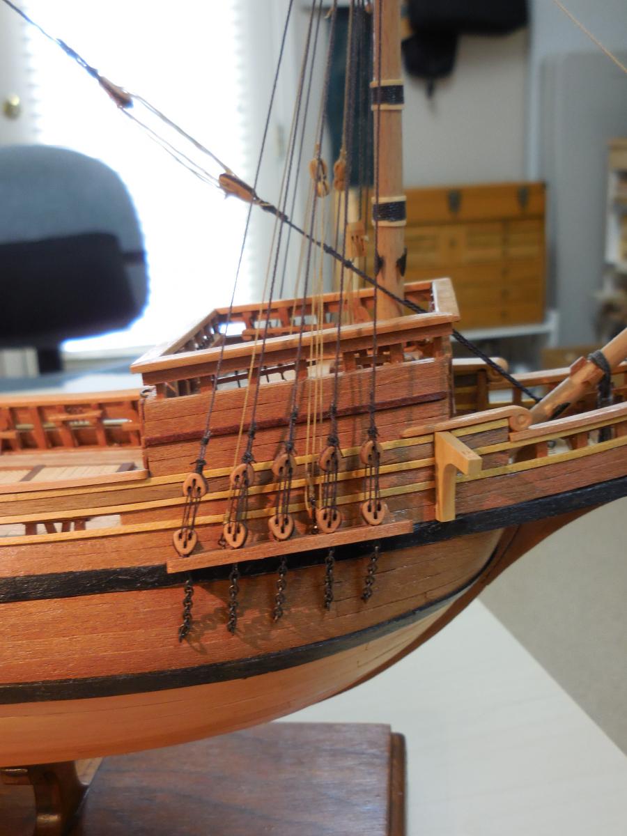
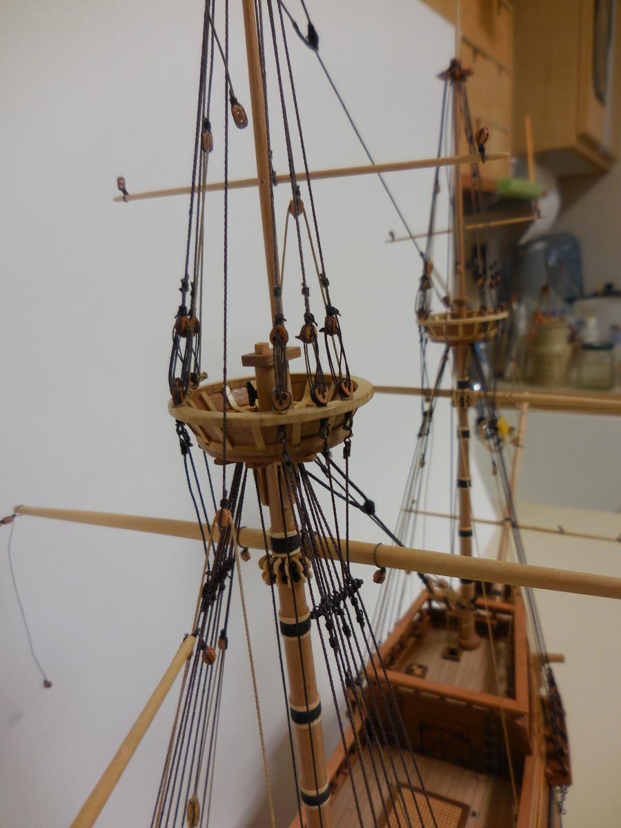
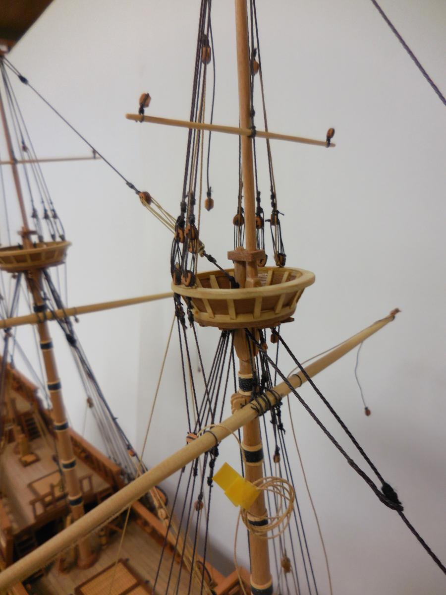
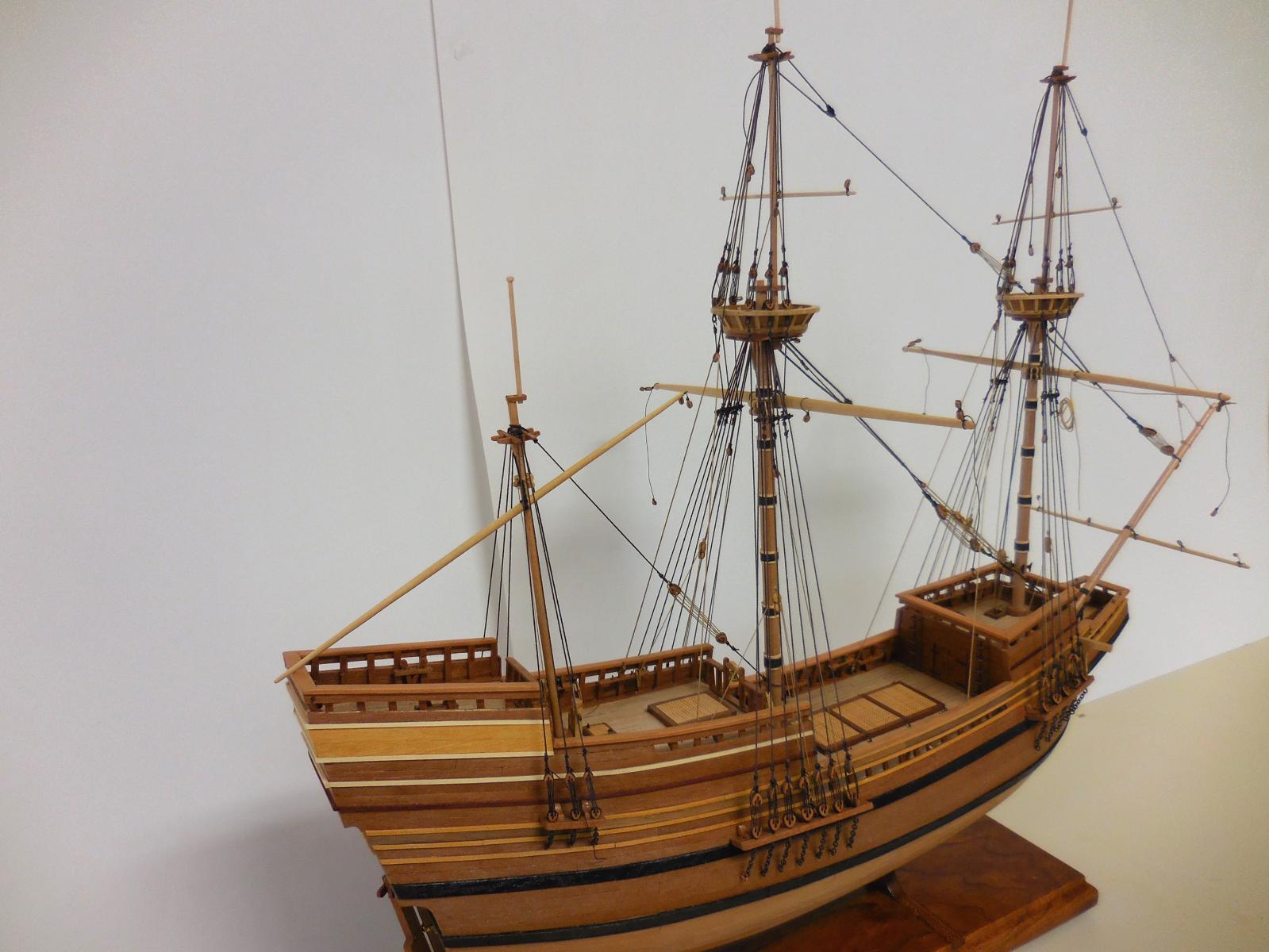
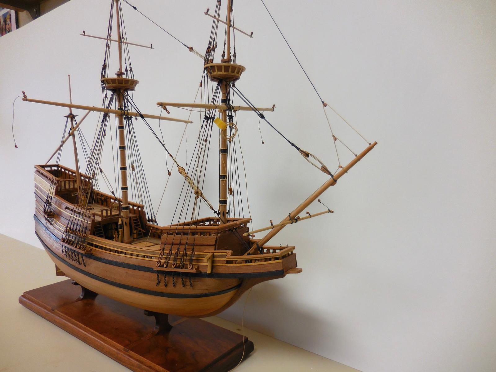
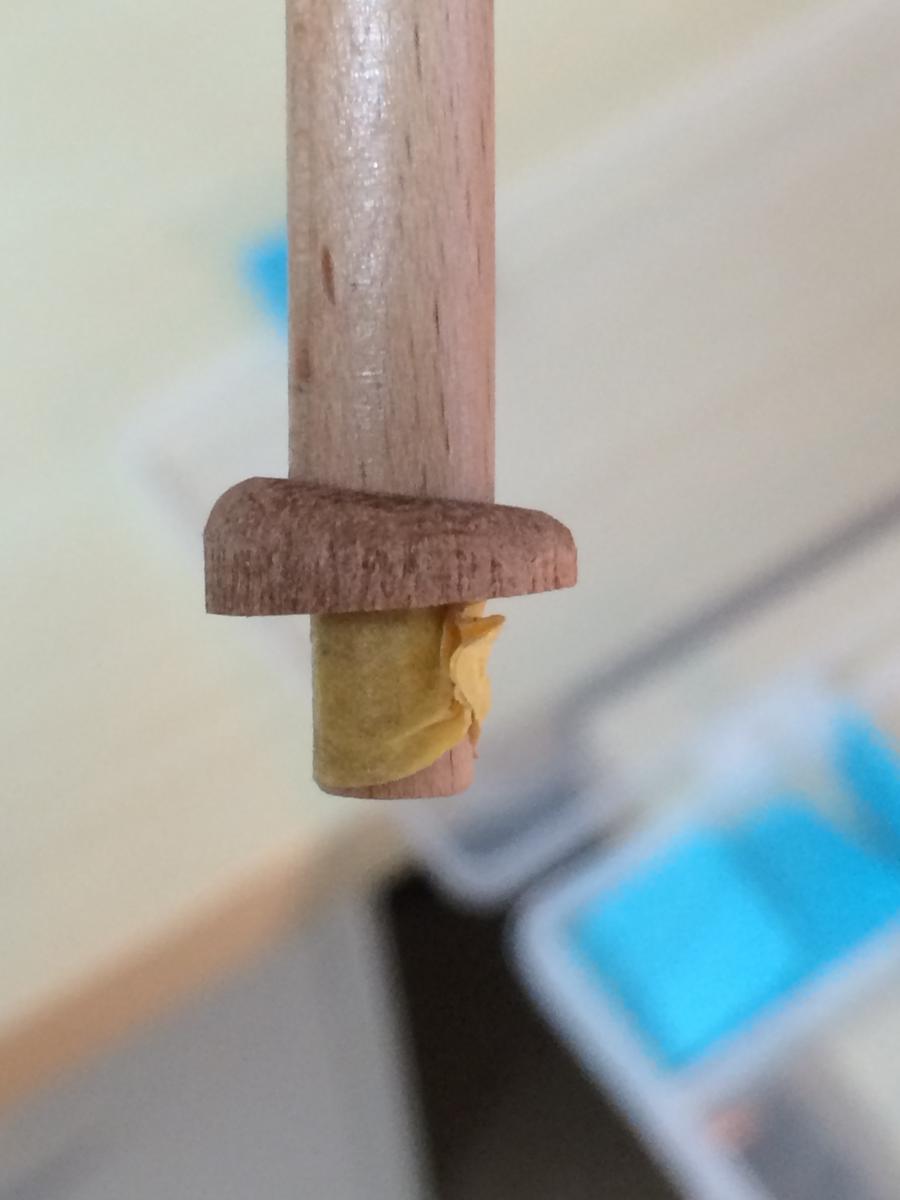
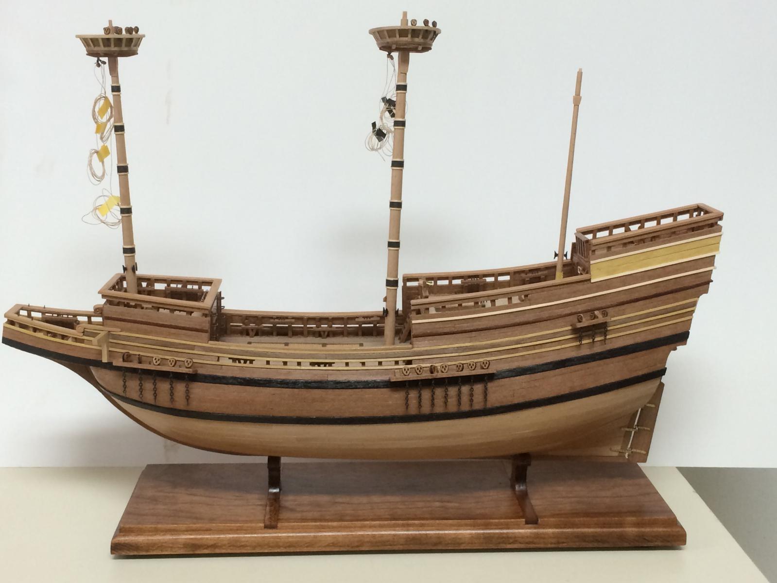
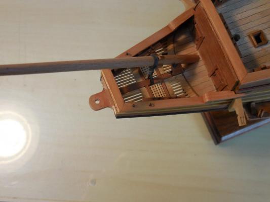
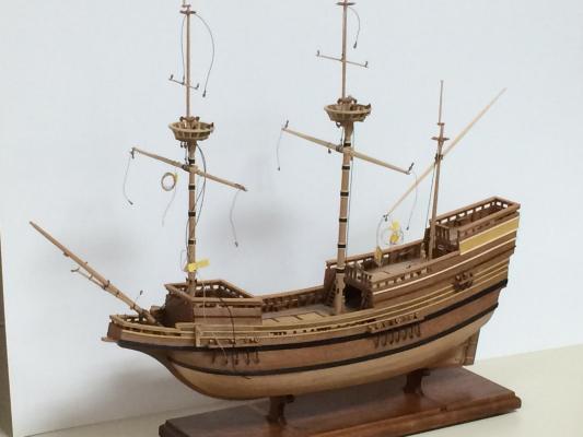
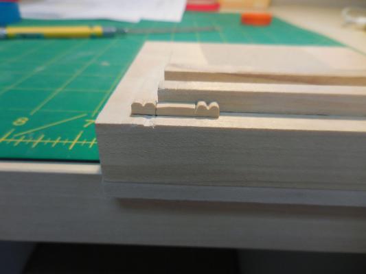
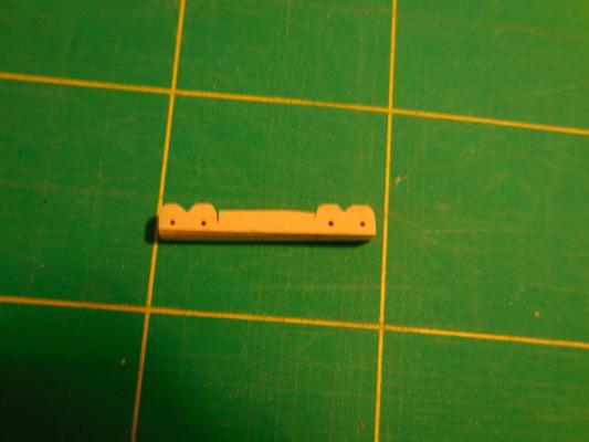
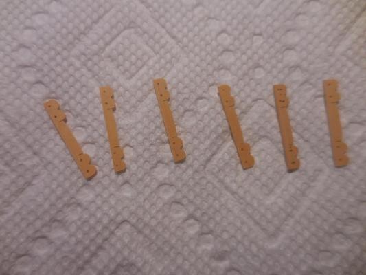
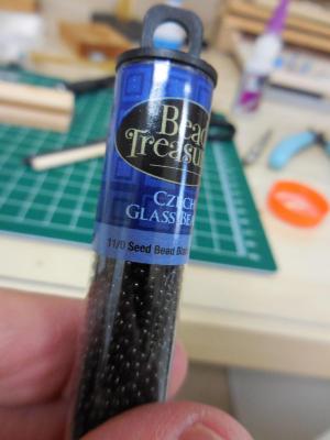
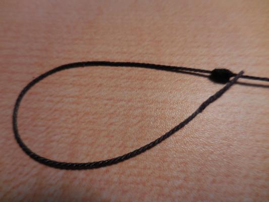
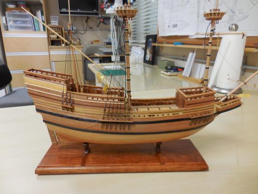
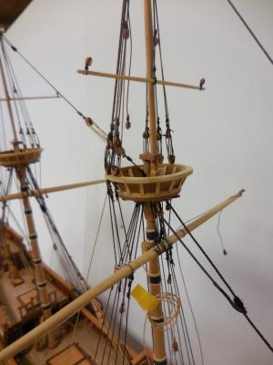
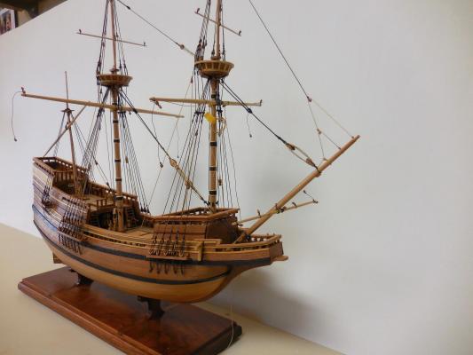
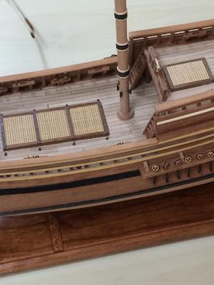
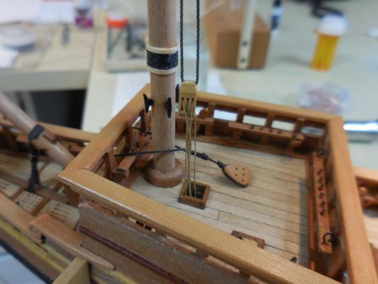
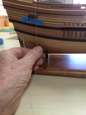
Paragon – a Modified Mayflower Part 18 – Standing Rigging Sorry for the delay since the last post – I’ve been dealing with some health issues. Hopefully we’ll get them cleared up soon. I had mostly finished the standing rigging and had started on the ratlines when I needed to put things aside. I’ll try to catch up here, but then it will be a while longer before I have any more progress to report. I decided to pre-rig as much as possible off the ship. It sounded like a good idea, since it would make it easier to bring line to the small blocks and other fixtures. Unfortunately when I started the standing rigging most of the pre-rigging was in the way so I removed it. You may see some lines on the ship in some photos, and then maybe will notice that they disappeared – that’s the reason why. Some of the pre-rigging made sense, so it was used. This mainly consisted of the rigging for holding the yards in place on the masts. If I had waited until after the standing rigging and ratlines were in place I’m sure it would have been much more difficult. Rigging started with the installation of the gammoning on the bowsprit. When I built the beakhead I had made a couple of small gratings for the area of the gammoning, and made them removable to give me more room to install the gammoning – they certainly helped. I pinned all of the yards to the masts, and installed the slings that were used for raising and lowering the yards. The slings for the mizzen yard and for the main course were brought to the related knightheads, since I thought this would be much more difficult once the standing rigging was in place. The following photo shows all of the slings in place. Parrels are part of the rigging on the main course and fore course, and also on the mizzen. They all serve to hold the yards in place. I started by milling castello to 1/32” strips and gluing them together using Ambroid glue. Once the glue was set I filed the middle area down, leaving the ends the size that the parrells would be. Then I used a small triangular file to make a cut in the middle of each parrell. Then, using a small parallel barrette file (and my favorite jig for fiing) I rounded over each wing of each parrell. Then I used a razor saw to cut halfway through between the parrell and the middle of the stock. This would make it easier to separate each parrell when ready to do so. Last task was drilling the holes for the lines through the parrells. Then a bath of acetone was used to separate the individual pieces When these dried I separated off the individual parrells at the cut I had already made. I used some 11/0 beads to make the parrells. I thought the parrells turned out pretty well. I needed some splices for the stays, so I made them by making the end of the line unravel then used some white glue to glue those frayed lines to the body of the line. I also need to make a mouse on each stay. I did this by wrapping some fine thread around the stay, using white glue liberally applied to keep the line in place. At this scale I didn’t think I needed to go through the effort to make a mouse the more traditional way. I decided to use ‘zip seizings’ on all of the lines that I could – in my opinion this is a much easier way to do seizings, and at this scale it looks better than anything I could do using a more conventional approach. (I learned this approach through Wooden Ship Modeling for Dummies by the late Hubert Secard). The following photo shows the tube created for seizings, along with a couple of seizings already cut from it. All of the standing rigging has been completed, and the following photos show the progression to the current state of the rigging. There are a few lines I will need to re-rig, but overall I’m pretty happy with it. The only rigging I have done prior to this is for the pilot ship Phantom, which is a much simpler rig. 100d When I get through the current issues I'll be tying ratlines, so I don't think I'll have any updates for a while yet. In the meantime, thanks to everyone who has been looking in.


-
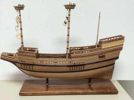
I'm going to follow along - looks like a nice kit for a friend of mine who is Japanese.
- 45 replies
-
- 3
-
-
- yakatabune
- woody joe
- (and 1 more)
-
Hi Brian I'm impressed, particularly with the sheaves you've been putting in. Are the sheaves wood or brass?
- 831 replies
-
- 3
-
-
- Armed Virginia Sloop
- Model Shipways
- (and 1 more)
-
Hi Bob She looks great! You and Patrick are masters in miniature.
- 127 replies
-
- 4
-
-
- dragon class
- yacht
- (and 1 more)
-
Hi Patrick The level of detail continues to amaze me. Your work is outstanding. Would love to see Symphony up close.
-
Gluing 101
Mahuna replied to CPT_D's topic in Building, Framing, Planking and plating a ships hull and deck
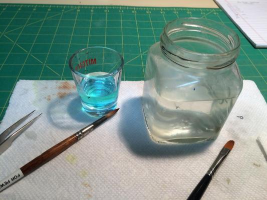
I agree with Druxey. In addition, for very small applications you could use a small syringe with a blunt dispensing needle. http://www.amazon.com/slip-tip-disposable-syringe-without-needle/dp/B007ZDHYTK/ref=sr_1_5?s=hpc&ie=UTF8&qid=1438914072&sr=1-5&keywords=syringe https://contenti.com/dispensing/dispensing-needle-tiplets I find the 26 and 27 gauge needles to give a microscopic drop of glue. I keep my syringe/dispenser combination point-down in a jar of water while I'm using them so the tip doesn't dry out. When I'm done I'll remove the tip from the syringe with glue in it and put it on a clean syringe filled with water. A few syringes worth of water cleans out the glue and lets you save the tip for a few more uses. At the low cost of the tips I buy 20-30 at a time and don't mind throwing one away. You could also get some tip caps so you can store the syringe with some glue in it. http://www.amazon.com/gp/product/B00BQ4IO84?psc=1&redirect=true&ref_=oh_aui_detailpage_o00_s00 This works well for PVA glue, but not for CA glue. Hope this helps. -
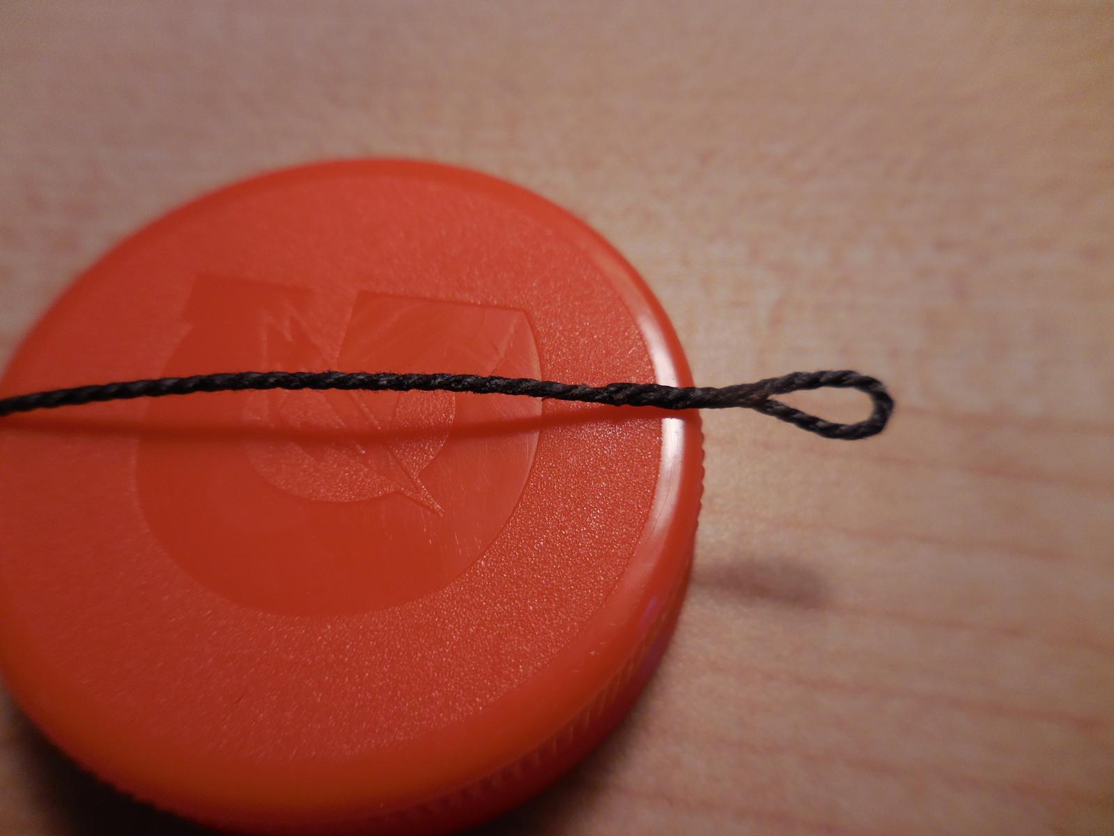
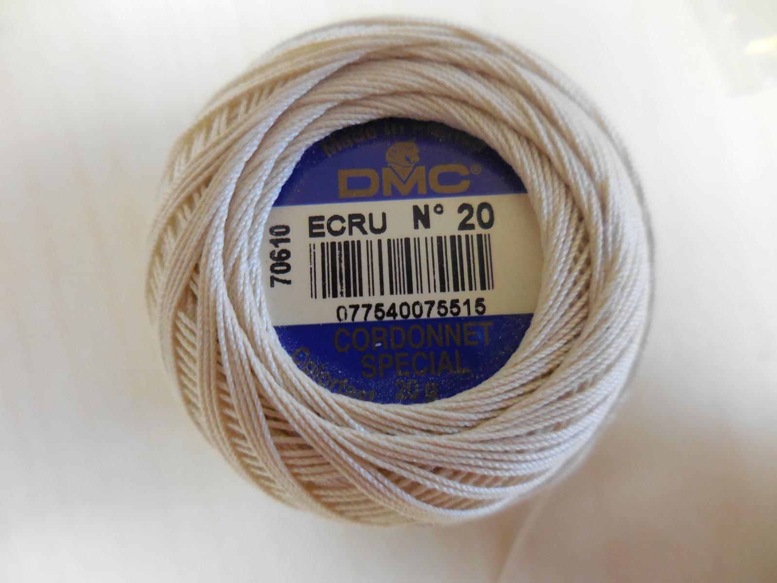
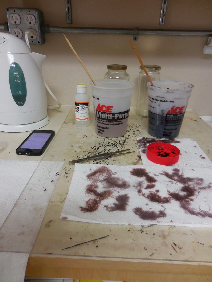
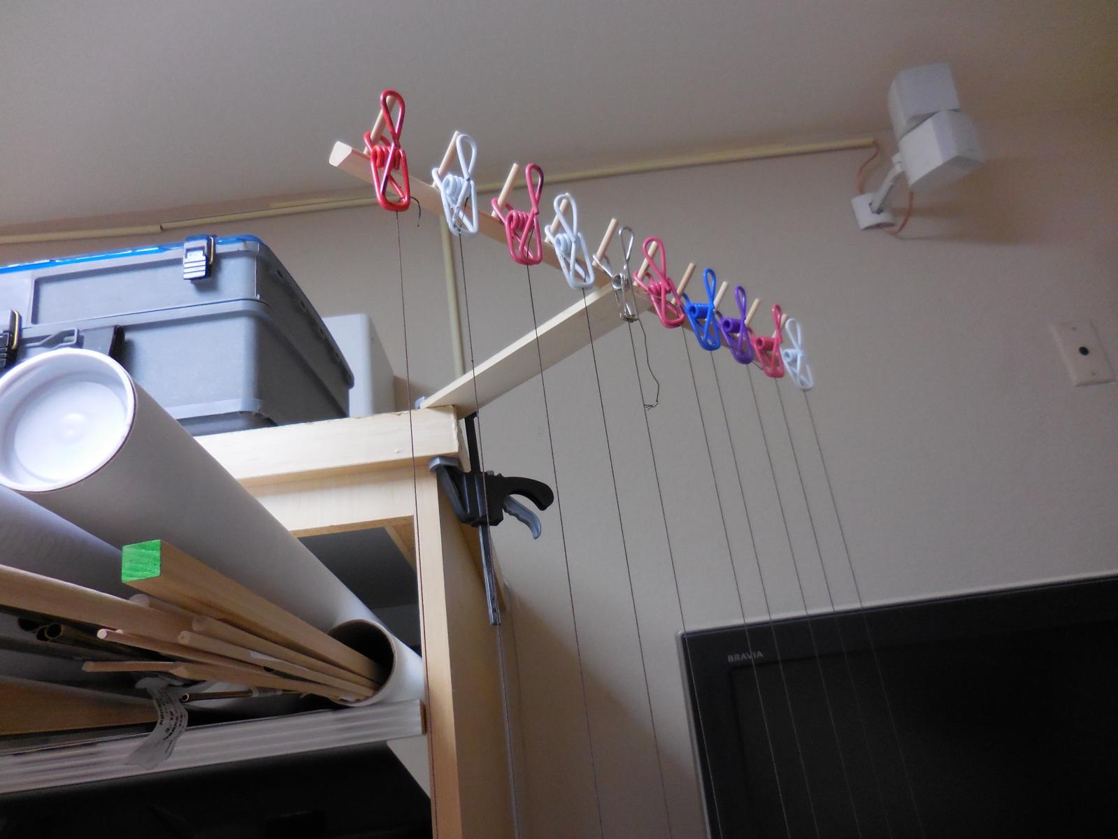
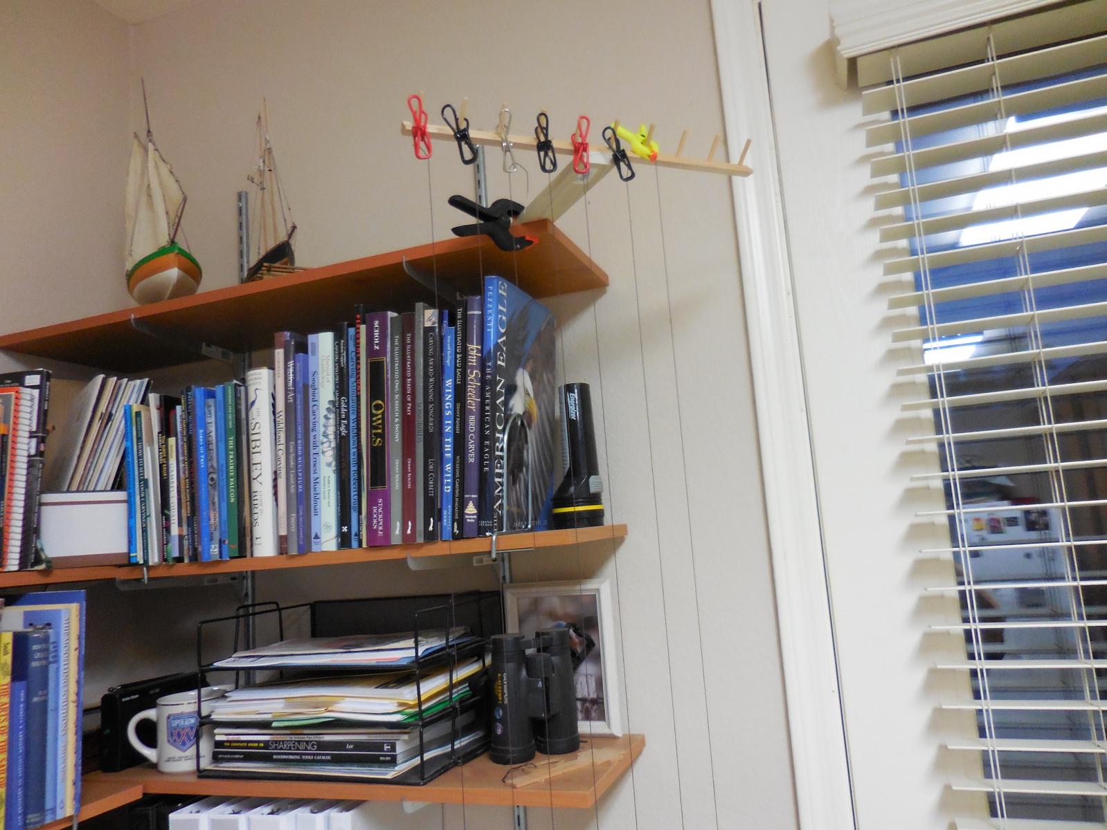
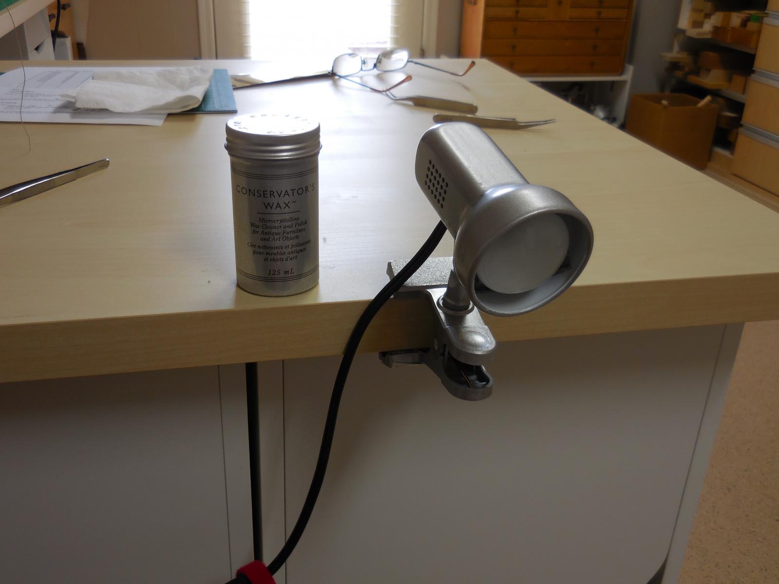
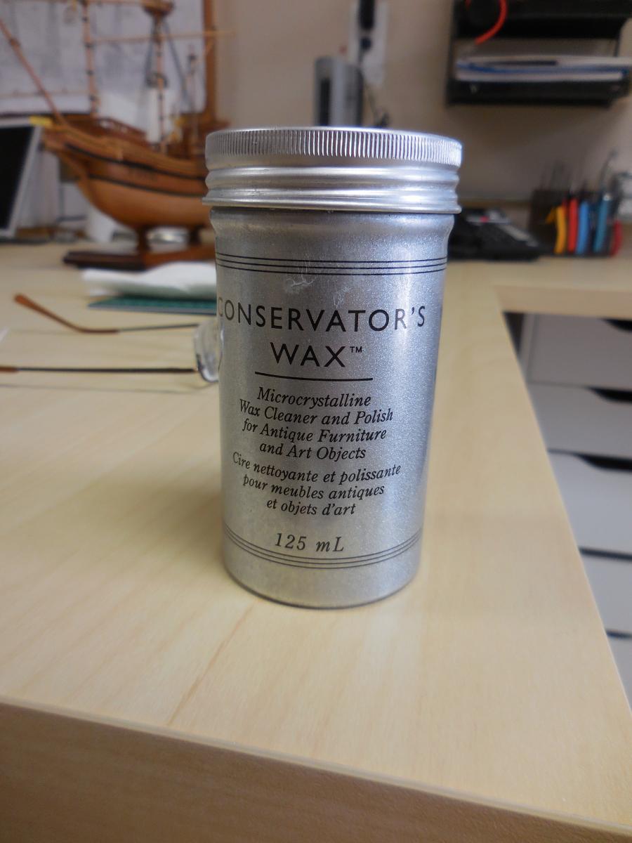
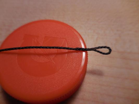
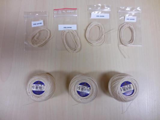
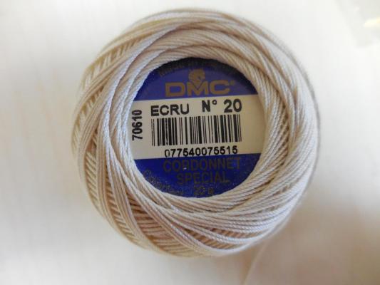
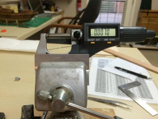
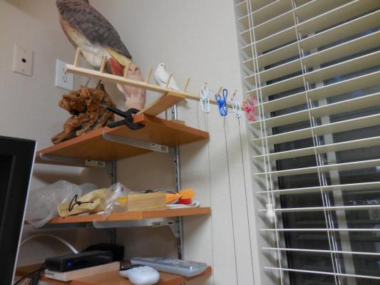
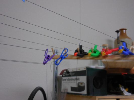
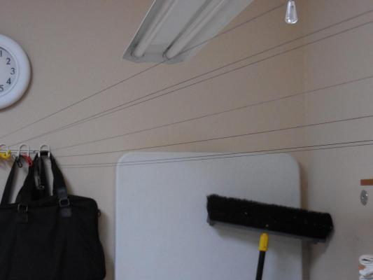
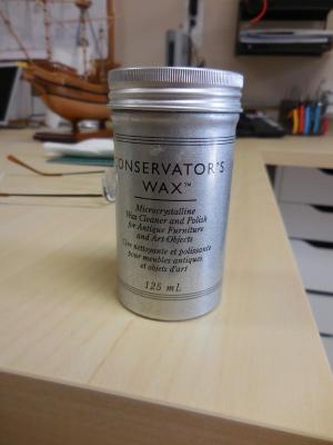
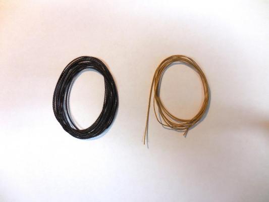
Paragon – a Modified Mayflower Part 17 – Making Model Rope I use DMC Cordonnet cotton crochet thread for rope making. It comes in several standard sizes, from 100 (smallest) to 20 (largest), and is very consistent in quality and color (I buy ecru-colored thread). It’s 100% cotton, which is my preference. The following photo shows some spools of the Cordonnet, along with some rope samples I’ve made with it. The thread itself has a very nice right-hand lay, so it can be used right off the spool if the size is right. I use the Prozak 3 vertical ropewalk from Domanoff Workshop. http://shipworkshop.com/products/tools/prosak-30 Using the Prozak, I made sample rope from all of the Cordonnet sizes, both 3 and 4 strand, and measured the diameter of the resultant rope (including single-strand right off the spool). I put together a reference sheet of all of the sizes. Rigging Line Sizes.pdf I’ve tried different methods for measuring model rope (and threads). First I used a traditional measuring stick, where you mark off a 1 inch gap, wrap the rope around the gap counting the turns, then divide the number of turns into an inch to get the size. This is fairly accurate, but the result will vary based on how tight or loose the windings are around the stick. I’ve also tried a digital caliper, but I find that no matter how gently I use it the rope gets compressed and the results will vary. I finally came up with the method I like best: I mount a digital micrometer in a vise, set an approximate sized opening, and slide the rope along the top of the measuring rod. By adjusting the opening until the rope can be moved through it with slight friction, we have the correct rope size. I find I can be pretty consistent in measuring to the nearest .001 inch (one thousandth). Initially I used India ink for coloring the rope, but I found that it made the rope fairly stiff and unnatural feeling. After reading how N. Roger Cole colors his rope using RIT fabric dye I started using that method. The standing rigging is a deep warm black (lots of brown undertones in it). The running rigging is a nice hemp color. The formulas I use are the same as Roger uses, with some minor modifications. The PDF shown above has the formula for each of the colors. First I boil sufficient water for the mixture. I put some in the first container, and add a wetting agent to the water. A measured amount of the hot water goes into the container for dying, and I add the appropriate amount of the various colors. I’ve found that as soon as the dye mixture starts to cool down the color will loose intensity, so if I’m dying a lot of rope I’ll mix a new batch when the mixture is only slightly warm. I use a product named Liquitex Flow-Aid as my wetting agent. You could also use Photo-Flo or any other wetting agent. In a pinch a few drops of liquid dish detergent would also work. The line to be dyed goes in the wetting agent for about 5 minutes, then is transferred to the dye solution for the specified length of time (7 minutes). When the time is completed the line gets hung for drying. The hangers I use are from a wooden rack for holding spools of thread, a reject from my wife’s sewing room. Each wooden arm has 10 dowels for the thread spools, and the whole contraption had 8 rows. I took it apart into the individual rows. When I get into ‘production’ mode, I have rope hanging all over. The lengths I make on the ropewalk are a little over 6 ft long, so these are hung vertically. For rope right off the spool, I generally use about 16 ft lengths, and hang these across the room. After the rope has dried overnight, it needs to be heat-set and waxed. Heat-setting will help the rope to remain color-fast. I don’t think this is so important in model rope, but since my wife told me I should do it I take the time to do so (one of my mottos is “a happy wife is a happy life”). I heat-set by running the rope over the hot housing of a small incandescent lamp that clips to the edge of my bench. I’ll generally make about 4 slow passes with the rope. When heat-setting is completed I normally hang the rope overnight again. I’ll skip this hanging if I’m in a hurry for a size. After heat-setting the rope, the next step is waxing the rope. I’ve tried beeswax but was never happy with the process. I’ve started to use Conservator’s Wax and I’m really pleased with it. I dip my index finger in the wax (it’s very soft and translucent) and rub the finger and my thumb together to spread out the wax, then run the rope through my coated fingers while rubbing the rope back and forth (a little of this wax goes a long way). I’ll do this 3 or 4 times, then I’ll run the newly waxed rope over the lamp I used for heat-setting, agin making 3 or 4 passes with the rope. The line is hung overnight again, and is then ready for use.


-
Thanks, Bob Not sure how to travel with it now, but perhaps. Of course, if you can ever make it down here to the Phoenix area I'd love to have you visit.
-
Hi Patrick: If you're going to do dinner plates, then why not cups and saucers, and then you'd need cutlery, then you'd need napkins of real fabric - what a slippery slope you're on! I'm really enjoying your skills and your imagination.
-
Thanks Patrick When we moved into this new home back in 2003, we converted a separate garage into this work space - 12 ft x 20 ft and air conditioned. Originally it was intended for my bird carving, but in the last couple of years it has become my model shipway exclusively. While I was still working I also used it as an office during my last couple of years of employment (I was a telecommuter), and it sometimes was hard to stay focused on work. Now that I'm retired I spend a good deal of my time there having fun. The gantry worked really well, but I have some ideas on making a new one out of brass and aluminum that can be adjustable and can be taken down for storage - a side project for sometime in the near future.
-
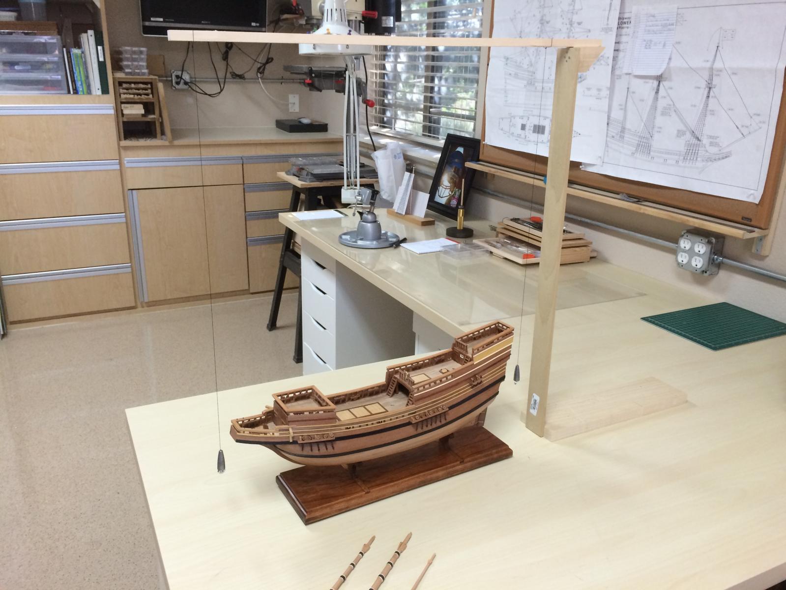
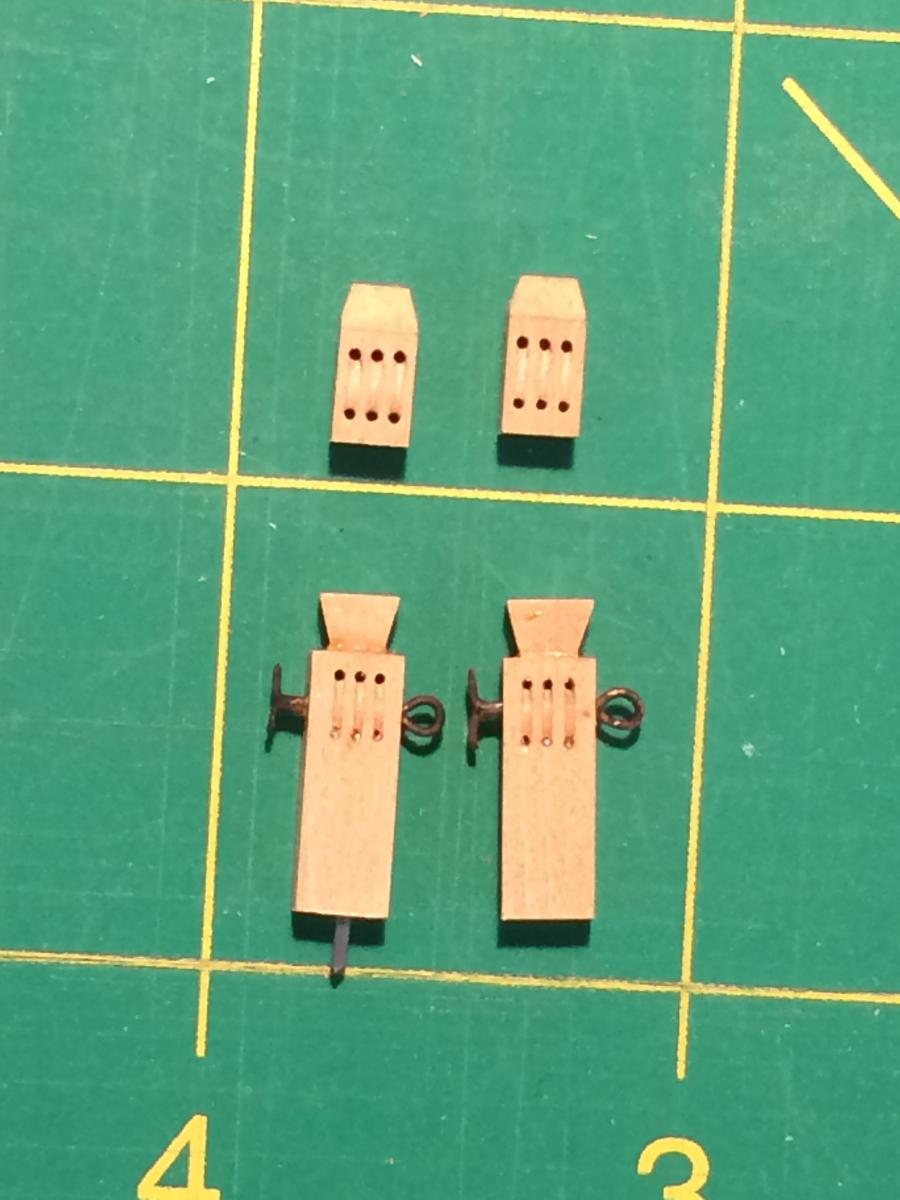
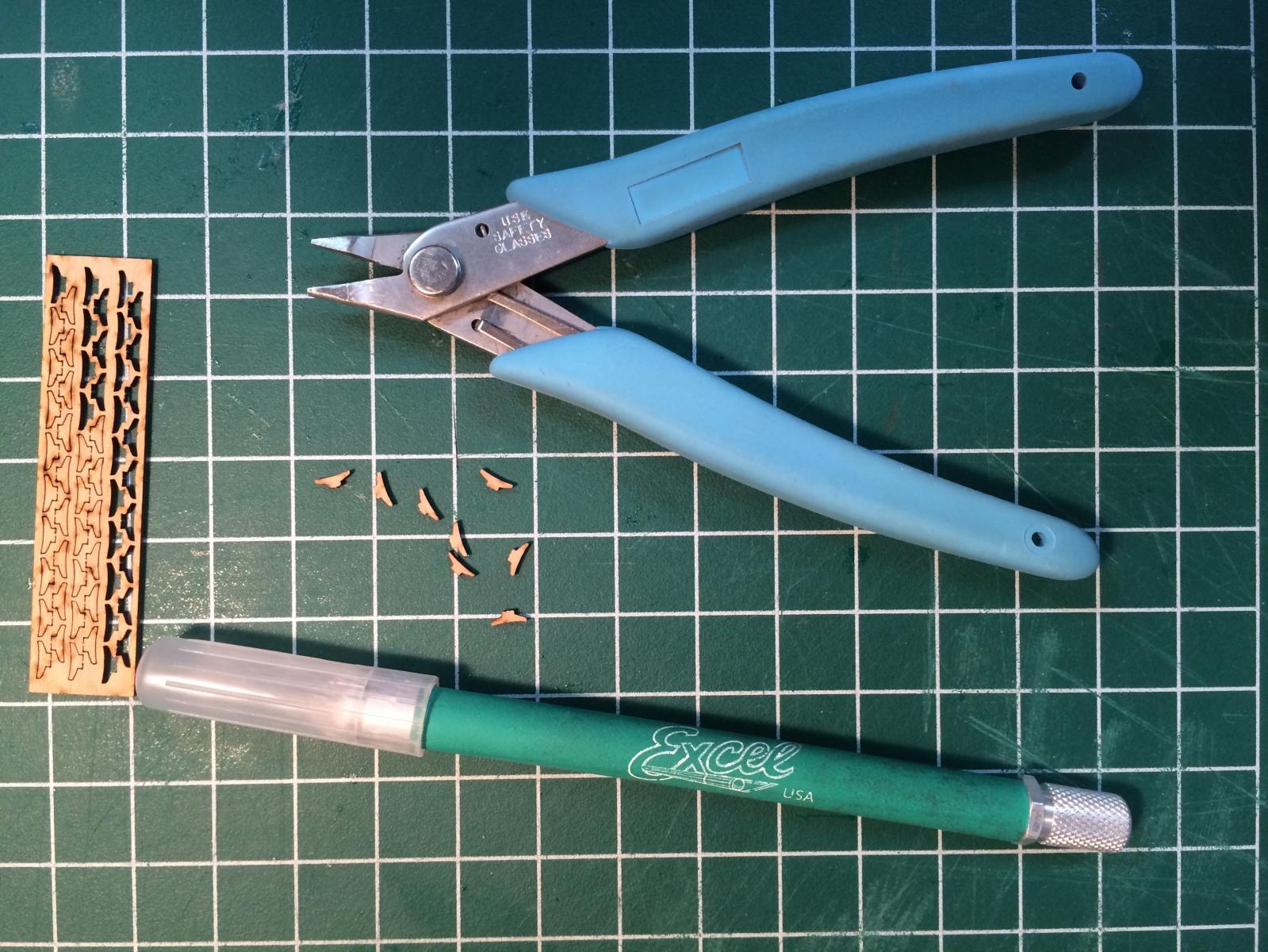
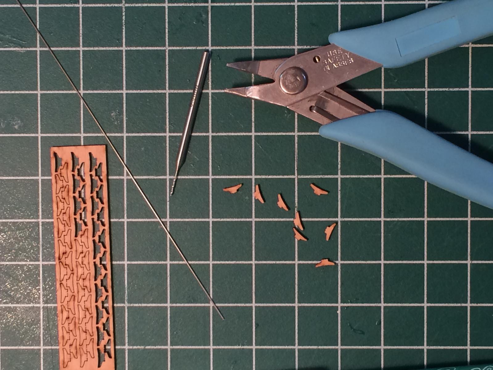
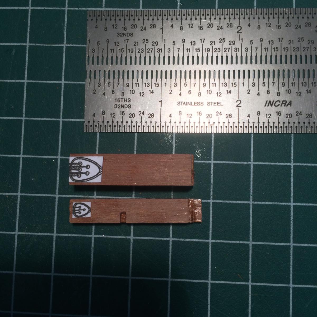
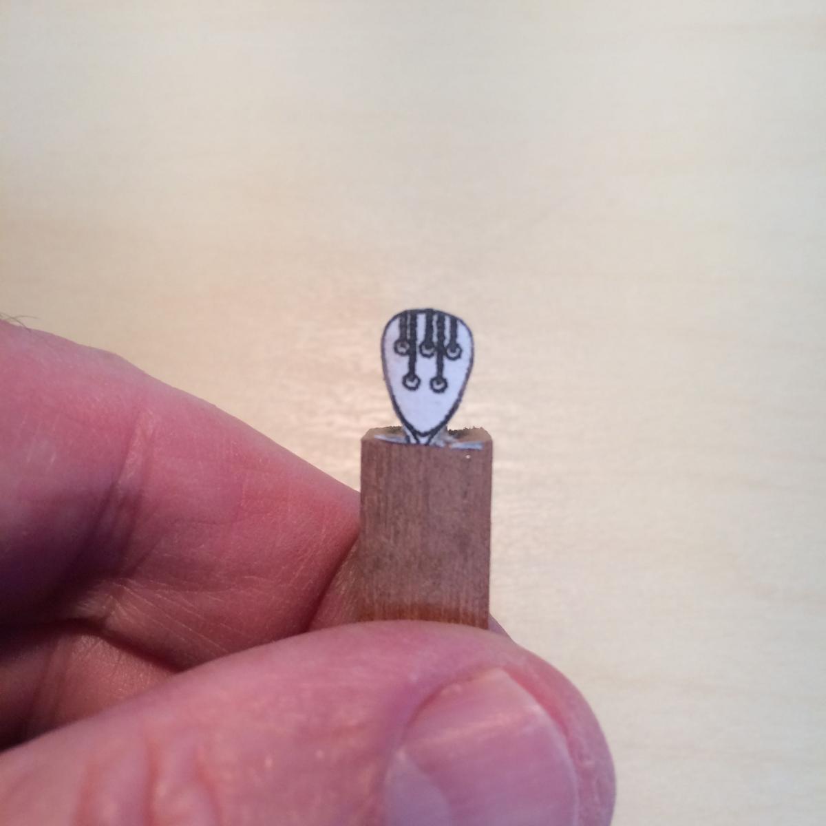
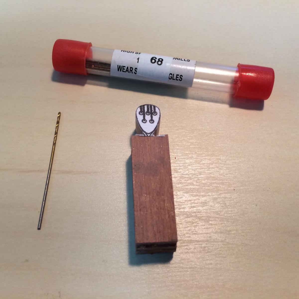
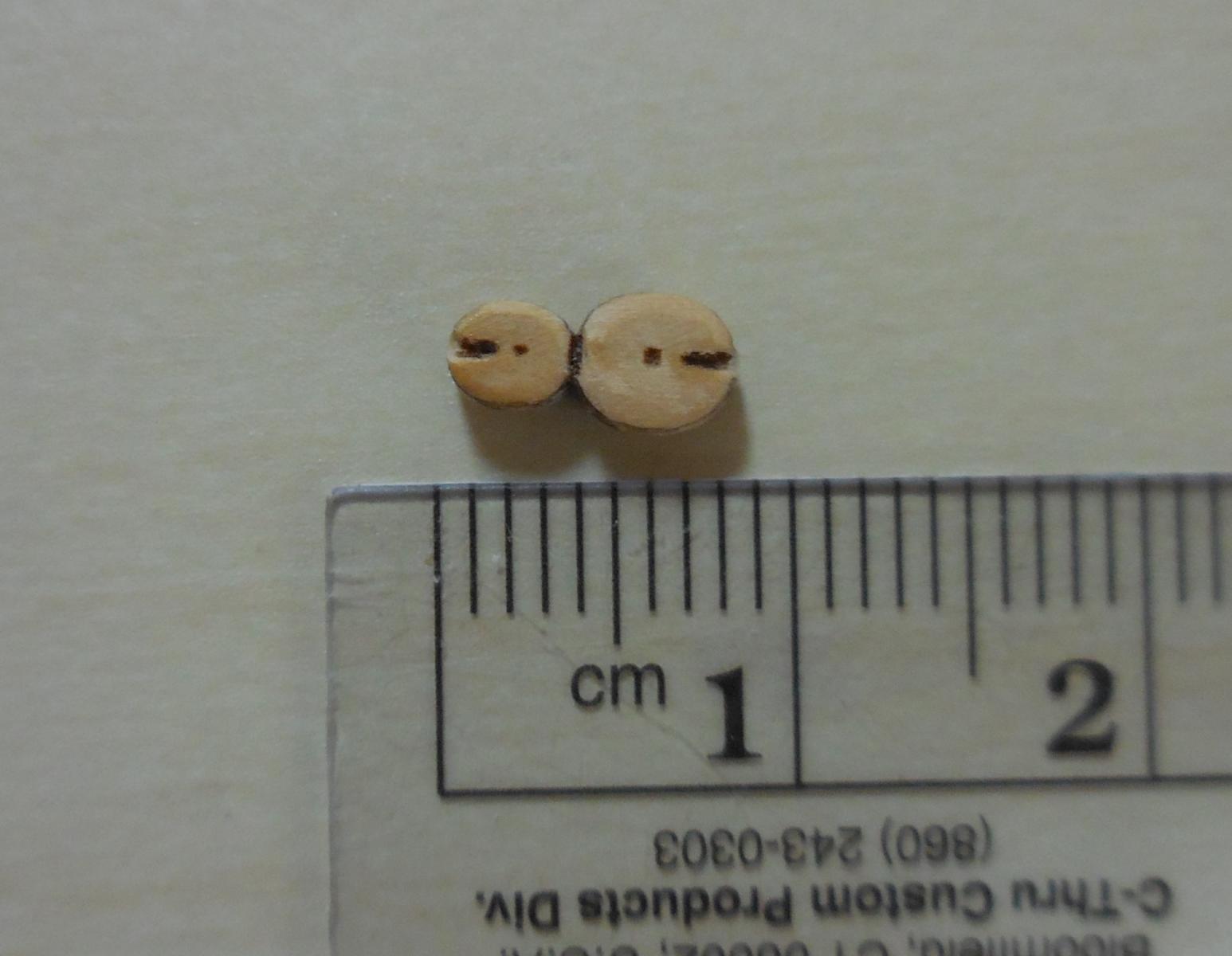
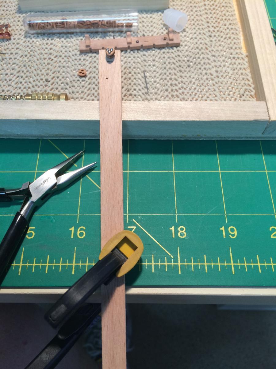
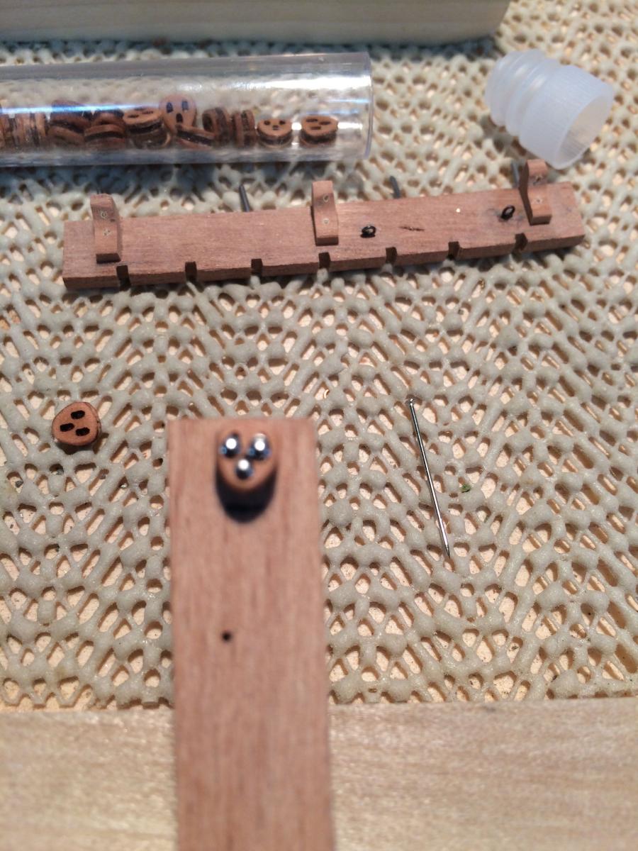
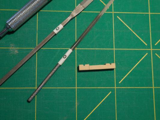
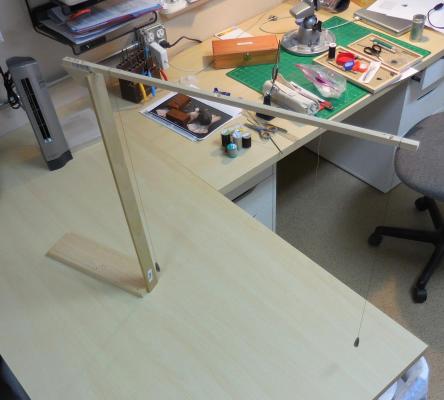
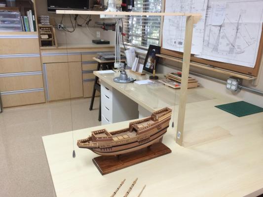
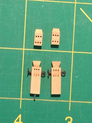
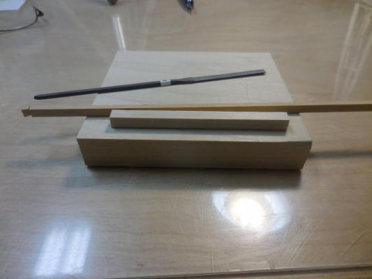
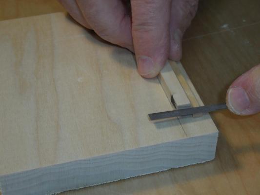
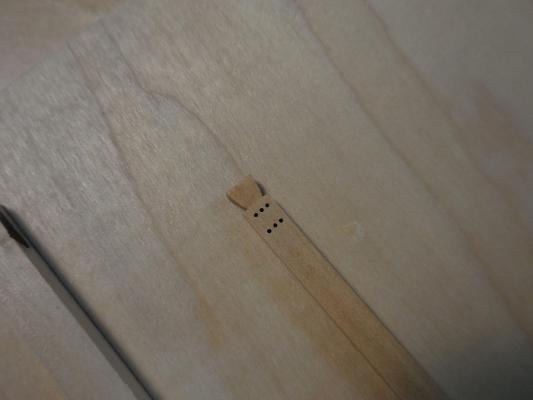
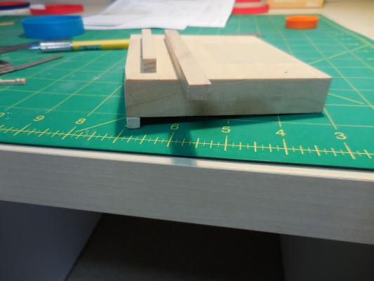
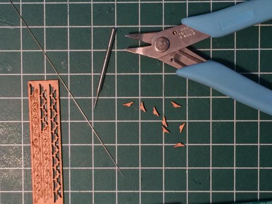
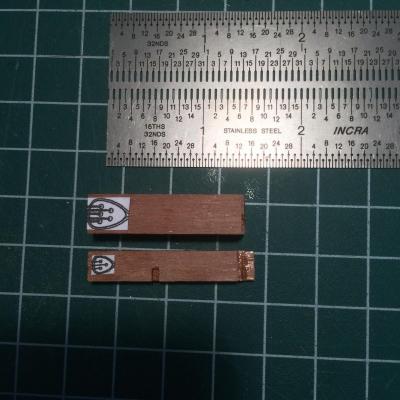
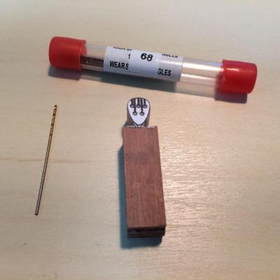
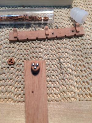
Paragon – a Modified Mayflower Part 16 – Final Work before Rigging When I had the masts, topmasts, Mast tops, and yards all fabricated, I thought it wouldn’t be long before I began the rigging for Paragon. Wrong – there was still a lot of small work to be done - I still needed to make a lot of the smaller items for the masts: tops, trees, cleats, and then needed to fit them together, poly them, etc. I made up a little checklist to make sure I didn’t forget anything: Mast Prep Work.pdf Before I could step the masts, I needed a way to ensure that each mast was at the correct angle – the foremast leans a little forward, the main mast is raked slightly aft, and the mizzen is raked aft a little more than the main mast. I hadn’t planned this out when I constructed the hull – simply drilled holes into the deck where the masts would be. I decided that the best way to maintain the angles I needed was to make mast coats that would hold the masts at the proper angle. Here’s the process that I used (sorry, no photos of the individual steps): I chucked a length of square wood in the lathe and drilled or bored the proper size hole for the mast. I removed the wood from the lathe and sanded the correct angle on one end using my Byrnes disk sander. With the wood chucked into the lathe again I machined the wood to the correct outside diameter and then parted the mast coat from the stock. This gave me a bottom that was slanted and a top that was level. The last step was to round off the top edge by hand sanding. I also needed a way to make sure the masts were truly vertical. I had read in an article by N. Roger Cole about using two vertical lines to eliminate parallax (def: the effect whereby the position or direction of an object appears to differ when viewed from different positions), so I built a gantry with two ‘plumb bobs’ (fishing weights) suspended from it. There was enough room and height to place the ship between the vertical lines of the plumb bobs. I first used the plumb bobs to make sure the ship was vertical in its base, then stepped the masts. The rigging also required some Knightheads and Ramshead Blocks. These were made of castello boxwood to ensure sharp edges and were fabricated using parallel Barrette escapement files and round escapement files. Since the cuts needed to be precise in a very small area, I put together a small jig that would let me hold the item securely and still use a very small file. The original jig had a flat bottom surface, and I needed to hold it tight so I added a cleat on the bottom which would help keep it in one position. Since all files cut on the forward stroke only, this helps keep the jig tight against the work surface. I made the base of the jig from thick stock so that my fingers would clear the work surface. This jig has become one of the most useful items for doing very small filing and cutting. Paragon also needed lots of small cleats. I tried making my own, using several different approaches in wood and brass, but didn’t want to spend as much time as it needed, so I bought some cleats from Syren Company (Chuck). These were perfect. The cleats need to be sanded to remove the laser burn, and to provide rounded sides where appropriate. They also should have small wire pegs inserted in them so that they can be securely glued to the ship. I used a .5mm drill with a 3/32 shank in my rotary tool, held the cleat with small pliers, and the variable speed foot pedal to drill. After gluing in the peg, I was then able to hold the cleat by the peg for the shaping. After being painted black they were mounted, and looked fine. In the above photo there’s a stay collar with fairly large triangular deadeye – I needed to make several of these. I started by gluing together 5 pieces of 3/32 flat stock using Ambroid glue, so that I could make 5 identical deadeyes. When set, a copy of the plan was glued to the group using a glue stick. The outline of the deadeyes were all shaped at the same time, by cutting the shape out on the scroll saw and sanding to the final shape. Then the holes were drilled through the stack of deadeyes using the Sensitive Drilling Attachment on my Sherline Mill. The deadeyes were separated by briefly soaking in an acetone bath. The groove around each deadeye was cut with my rotary tool and finished off with a small round escapement file. The final shaping was to provide the gentle roundness to the edges of the deadeye. Finally, the ship needed Fiddle Blocks for the various tackles, so I used the Fiddle Block kits sold by Syren - they were easy to make and did the trick. So Paragon is ready for rigging, but now we need rope to do it with. How I made model rope will be covered in the next part.


-
Hi Brian There's a product called Kool Jool that is used to protect precious stones while soldering. I'm thinking that if it was put on a joint that was already soldered it would protect the joint. I actually have had a jar for a while, but haven't gotten around to testing it. You're welcome to borrow it to try it out. https://contenti.com/kool-jool Another little trick that has worked for me is to wrap the soldered joint in a piece of paper towel that has been soaked in water. It normally protects the joint long enough for the soldering of the adjacent joint to be completed. Of course, this all depends on how much room there is between joints.
- 831 replies
-
- 4
-
-
- Armed Virginia Sloop
- Model Shipways
- (and 1 more)
-
Brian - Now that you mention it - I wrapped the wire fully around the deadeye (the double wrap still fit within the grooves around the deadeyes), then wrapped both sides around the 'stem' under the deadeye. This is where the lack of precision came in - I didn't take care that each deadeye was wrapped identically. With your level of precision (and the forewarning) you should be fine. Your deadeyes are probably a lot larger than the ones I dealt with, and being round may be easier as well.
-
Hi Brian: The jig was very simple - three holes lined up with the holes in the deadeye. I used pins to hold the deadeye in place. Another hole for a pin through the bottom link of the length of chain to be used. I held the jig on the workbench using a clamp. For the process I followed the Mayflower instructions: Stropping Deadeyes.pdf Hope this helps. If not, let's talk.

-
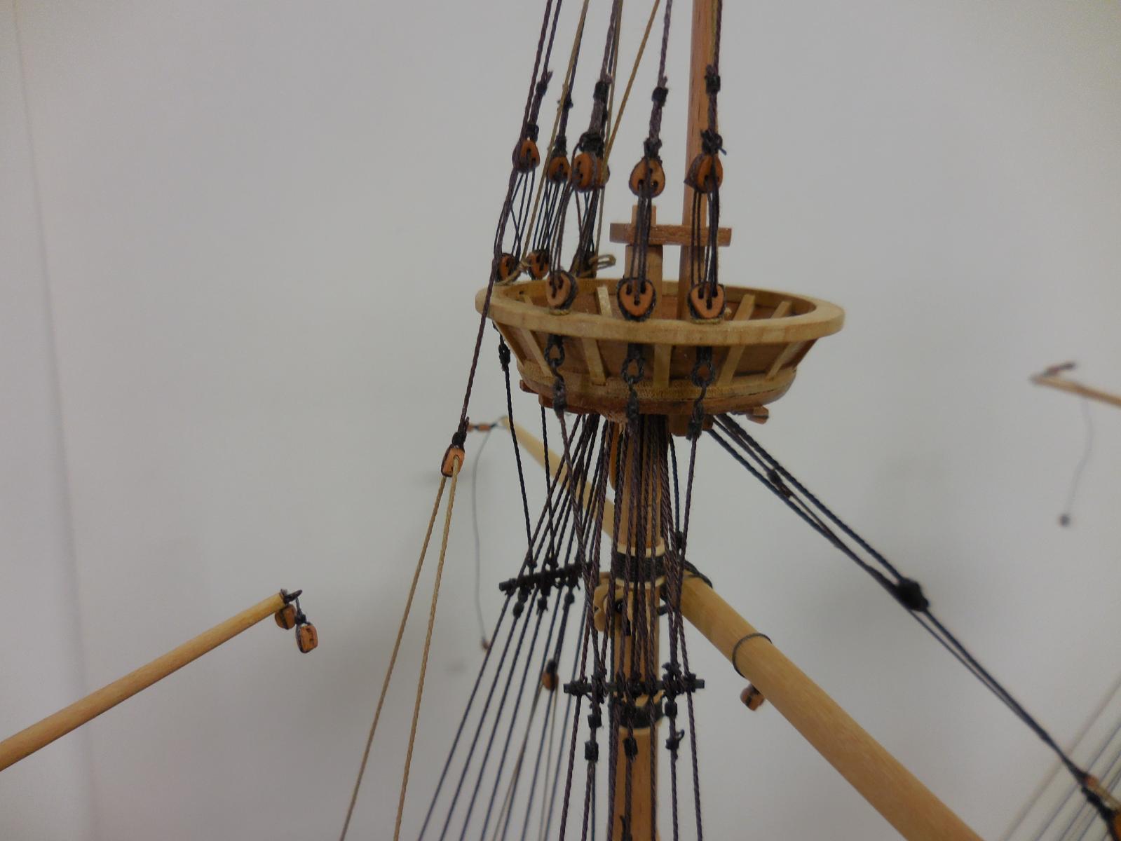
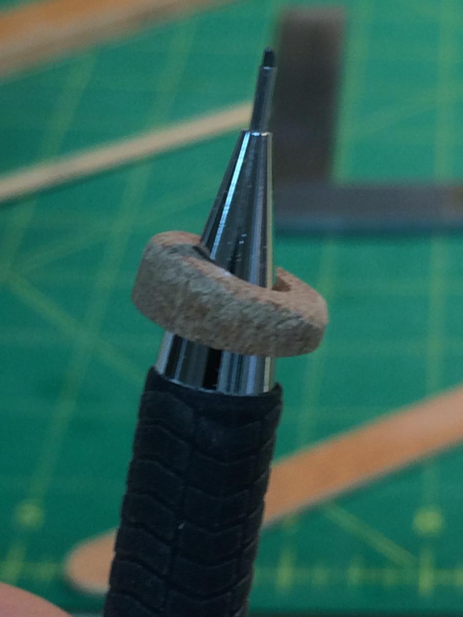
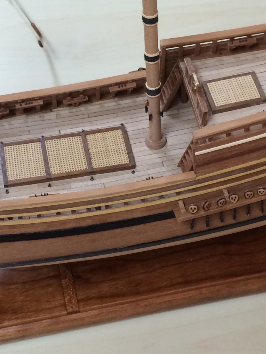
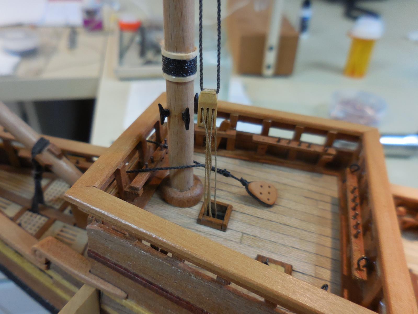
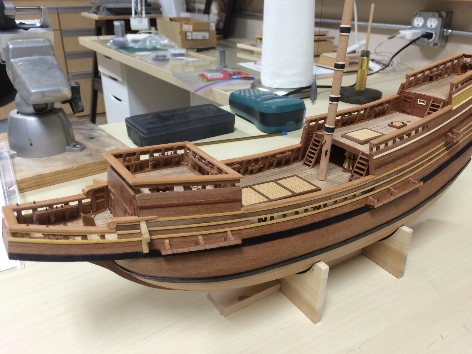
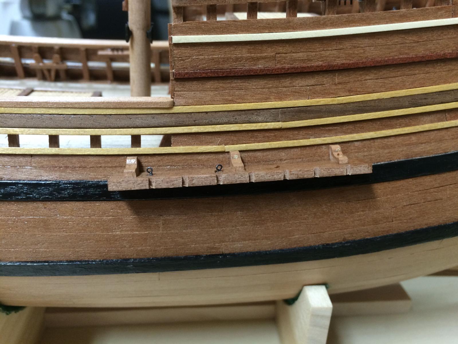
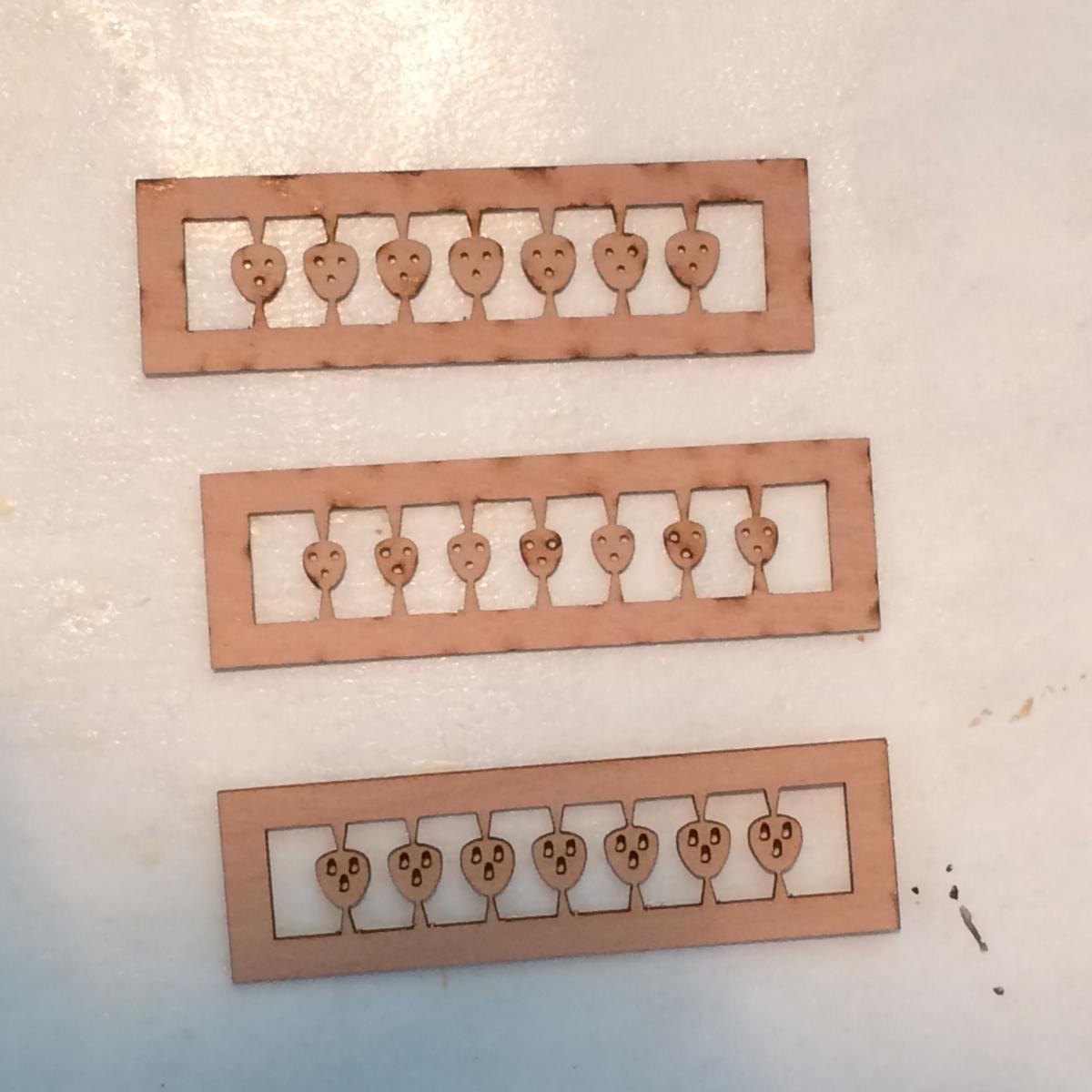
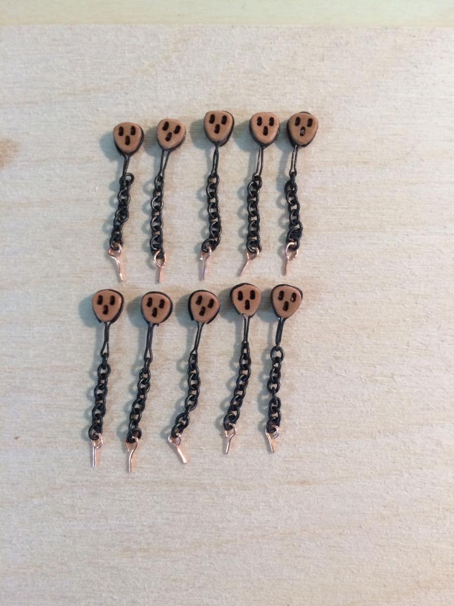
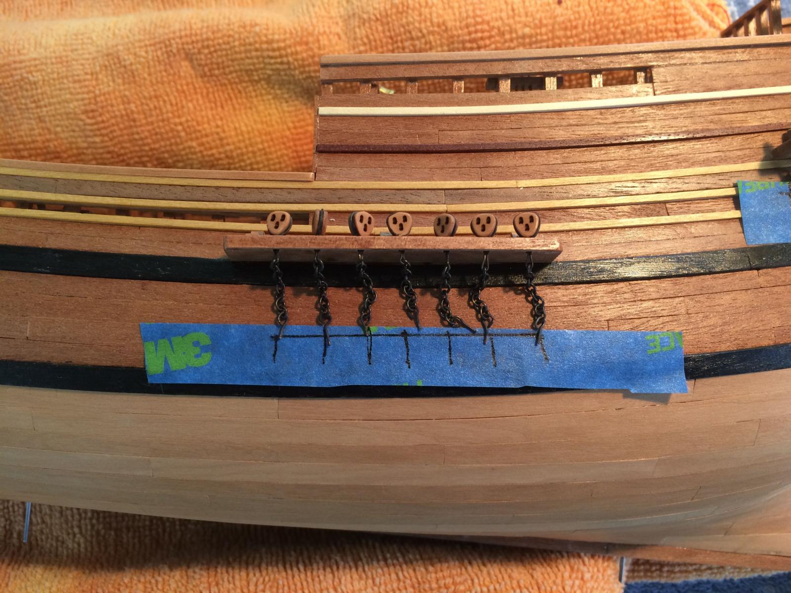
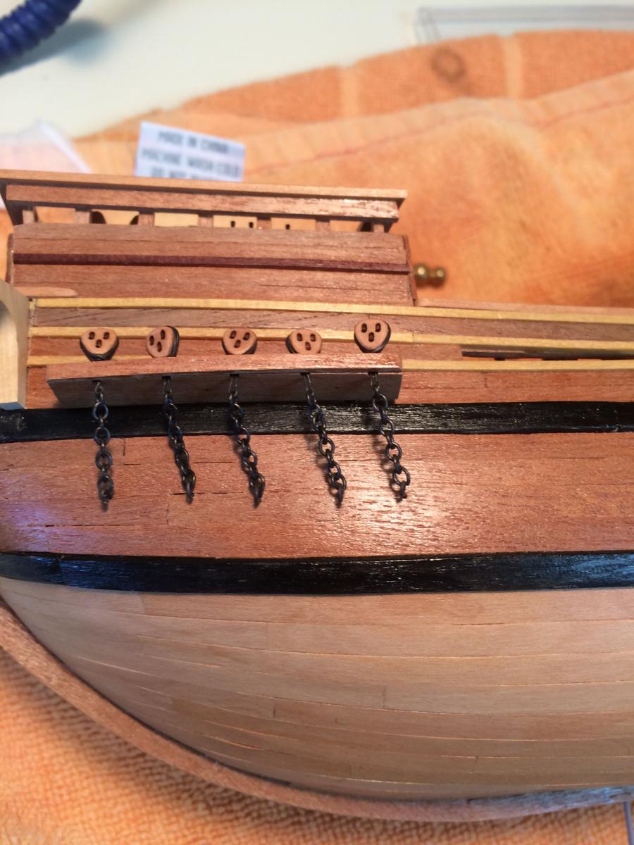
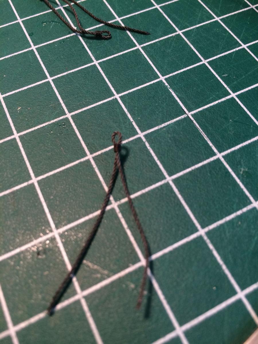
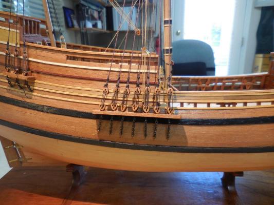
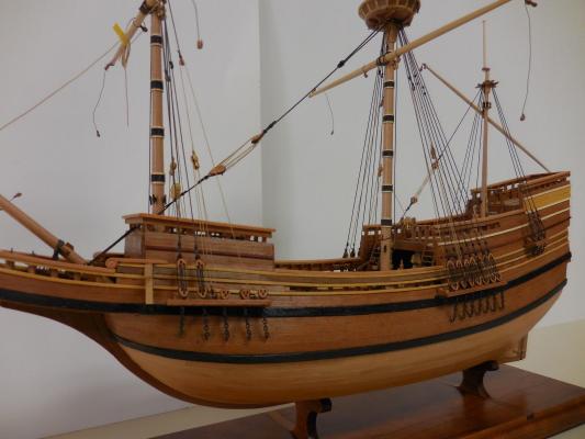
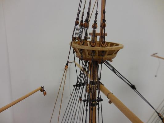
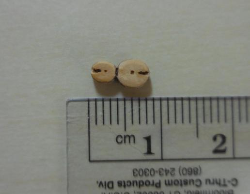
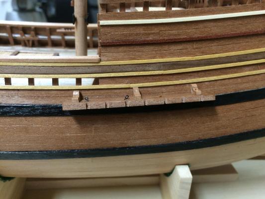
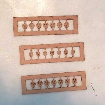
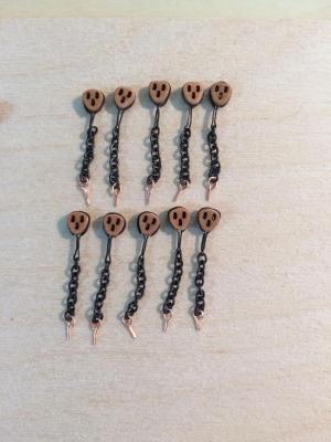
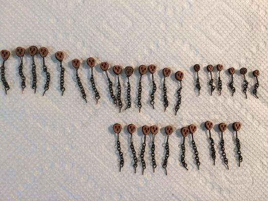
Paragon – a Modified Mayflower Part 15 – Channels and Deadeyes The channels were pretty straightforward – the hardest part was shaping the interior edge so that it laid properly against the hull. The channels need to follow the curve of the hull for and aft, but also need to match the up and down slope of the hull. This was accomplished by test fitting numerous times, then making very small adjustments until I was happy with the fit. I made pegs of steel wire to hold the channels to the hull. The support brackets above the channels are for appearances only. Originally I had planned to drill and peg these, so I made them thicker than they should have been. Too late to change them without serious rework. The Mayflower had triangular deadeyes of two different sizes. I gave some thought to producing them myself and even developed a couple of prototypes. On further thought (and using my basic arithmetic skills) I realized the amount of effort (and time) it would take to produce the number needed – about 90 of them, in two different sizes. So I contacted Chuck (Syren Company) and he made them as a custom order – I received them within a week! The lower deadeyes would be secured to the hull using chain, so I needed to strop the deadeyes to the chain. I made up a simple jig to get this done. I was able to get the deadeyes and chain set up pretty quickly, and I made eyebolts from copper wire for attaching the chains to the hull. After blackening the copper parts I was ready to install the lower deadeyes. I installed some fake masts so that I could mark off the run of the shrouds, using a line attached to the top of each mast. I put some masking tape on the hull so that I didn’t need to mark the hull itself, and drilled through the masking tape at the appropriate marks. I’m fairly happy with the results, but now that I’ve begun the standing rigging I have experienced some small problems that I would avoid next time. My method of stropping to the chain was OK, but I needed to pay closer attention to getting the gap between the deadeye and the chain uniform. The deadeyes turn very easily, which makes it hard to install the lanyards while keeping the deadeyes lined up. The mast tops each have six small deadeyes, three to a side. These deadeyes are for the shrouds to the top mast, but they also secure the rings that will hold the futtock shrouds. To make these rings, I seized an appropriate piece of rope around a drill bit. (The following photo is a little out of focus, but it’s the only one I have of the rings before installation). The lines were run up the holes in the mast top for the deadeyes, then the lines were held in a spread position (not glued) to the railing of the mast top. A deadeye was then glued to the spread lines. After the glue was set, one side of the line was glued to the deadeye. Then the opposite side was glued and trimmed when set. The mast tops were temporarily fixed to the fore and main masts, and the three masts were temporarily stepped (because I was anxious to see how it looked after all the work). The next post will address the completion of the masts, and will cover some miscellaneous details required for the rigging.


-
Hi Dan Glad I found this build - I remember the tragic event. I especially like the details you provide on your research and on the various processes followed in this model build. I play to stay tuned!
- 108 replies
-
- 1
-
-
- andrea doria
- ocean liner
- (and 1 more)
-
Thanks all for the nice comments and the Likes. It encourages me to keep on keeping on.