Mahuna
-
Posts
1,504 -
Joined
-
Last visited
Content Type
Profiles
Forums
Gallery
Events
Everything posted by Mahuna
-

replacement for blacken it brass?
Mahuna replied to rtropp's topic in Metal Work, Soldering and Metal Fittings
JAX Chemical sells a product called Pewter Black that blackens brass, copper, and solder, and has even blackened the ferrel on the paintbrush I use to apply it. http://www.jaxchemical.com/jaxshop/shopexd.asp?id=129&bc=no -
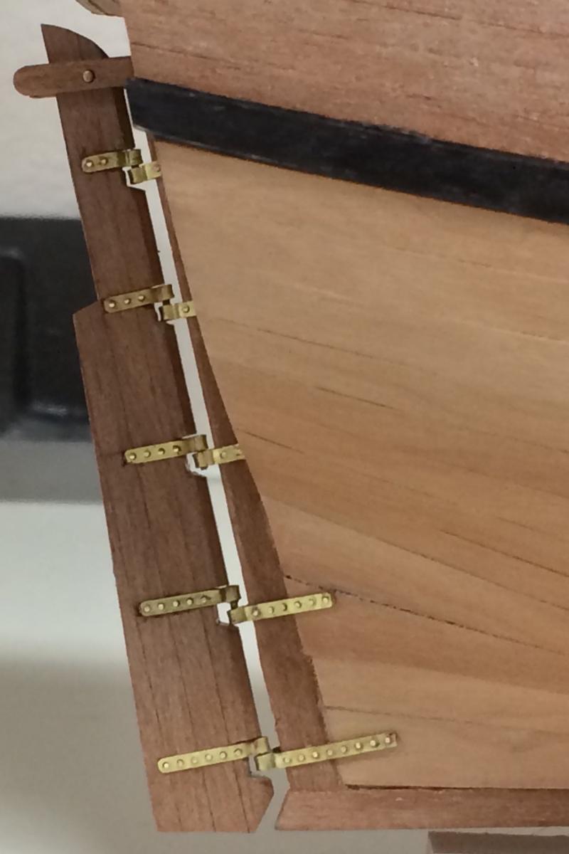
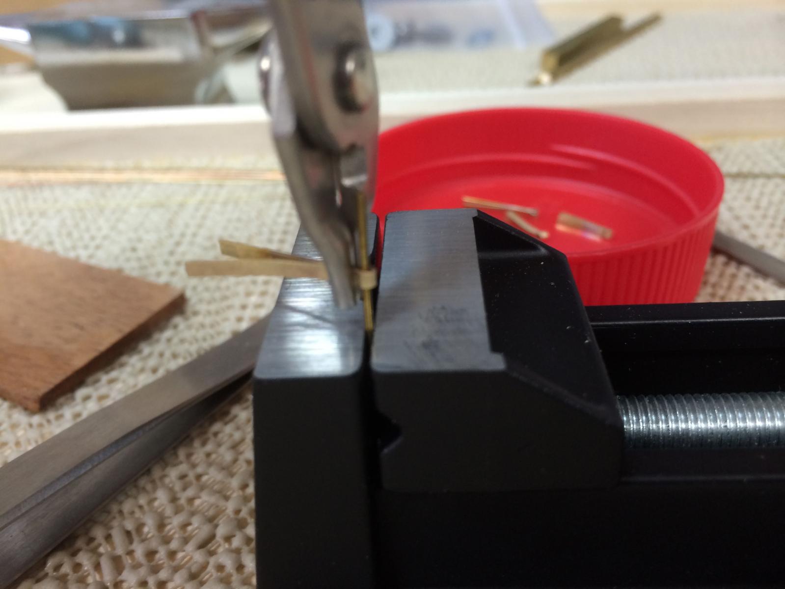
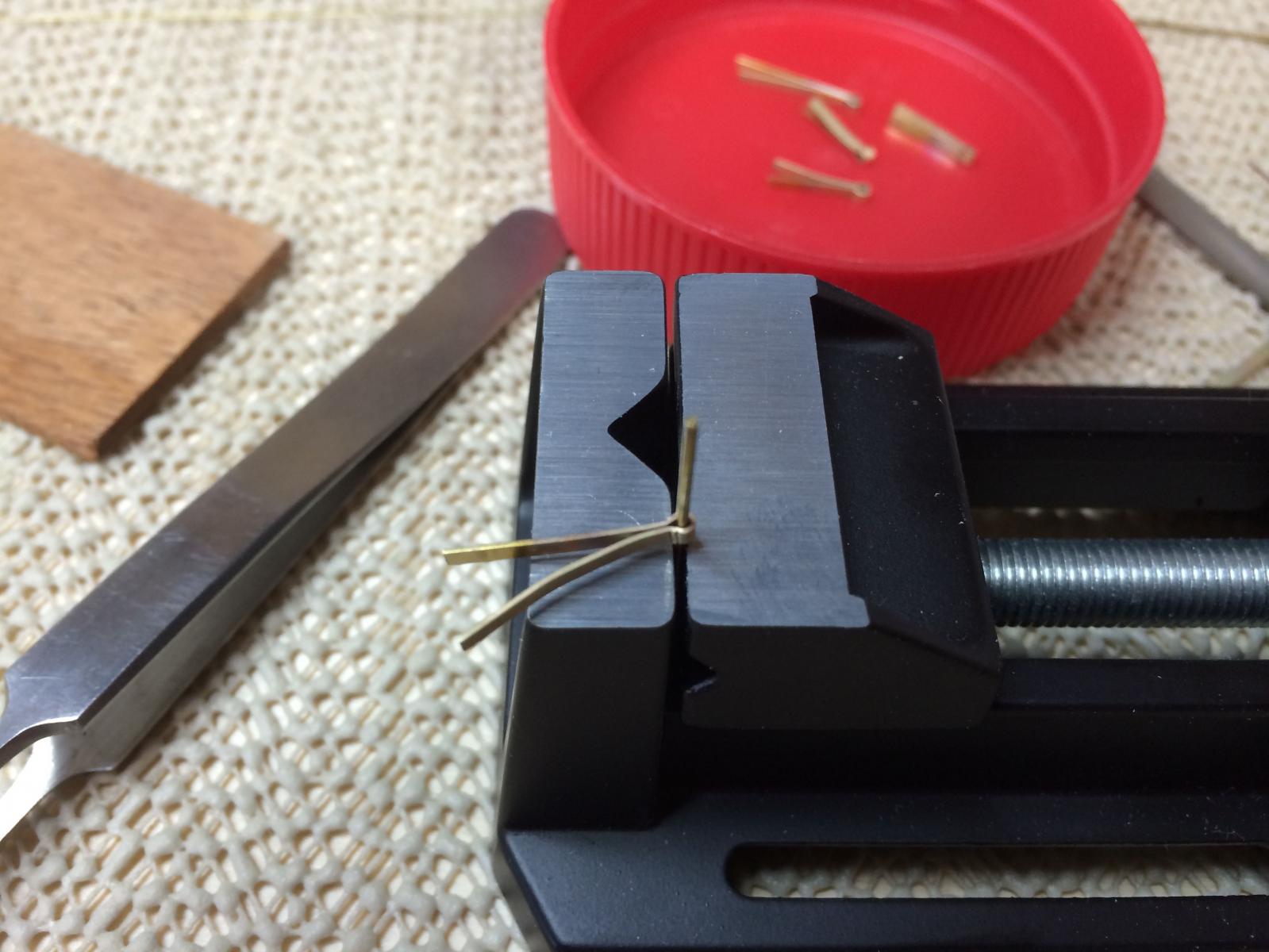
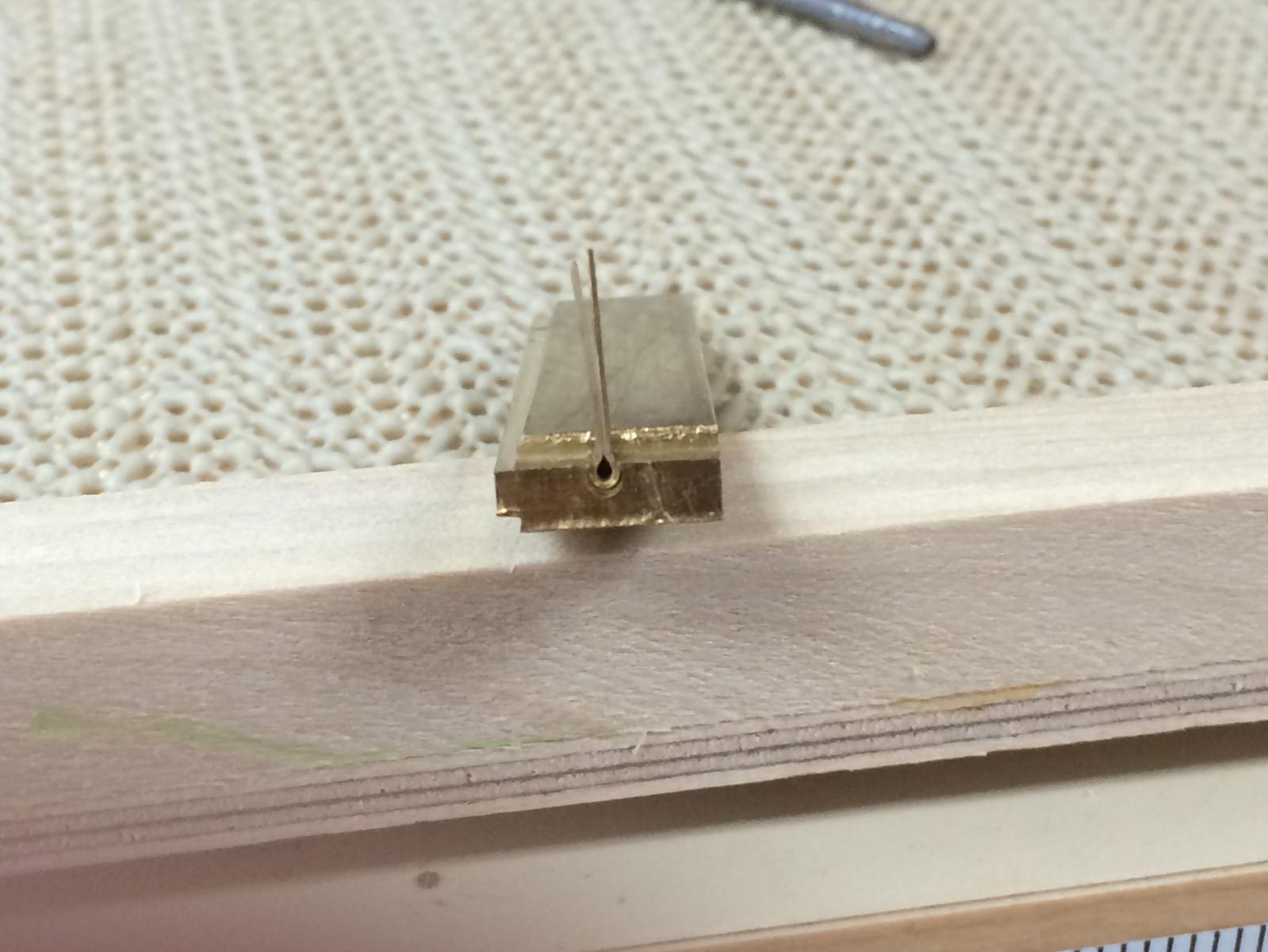
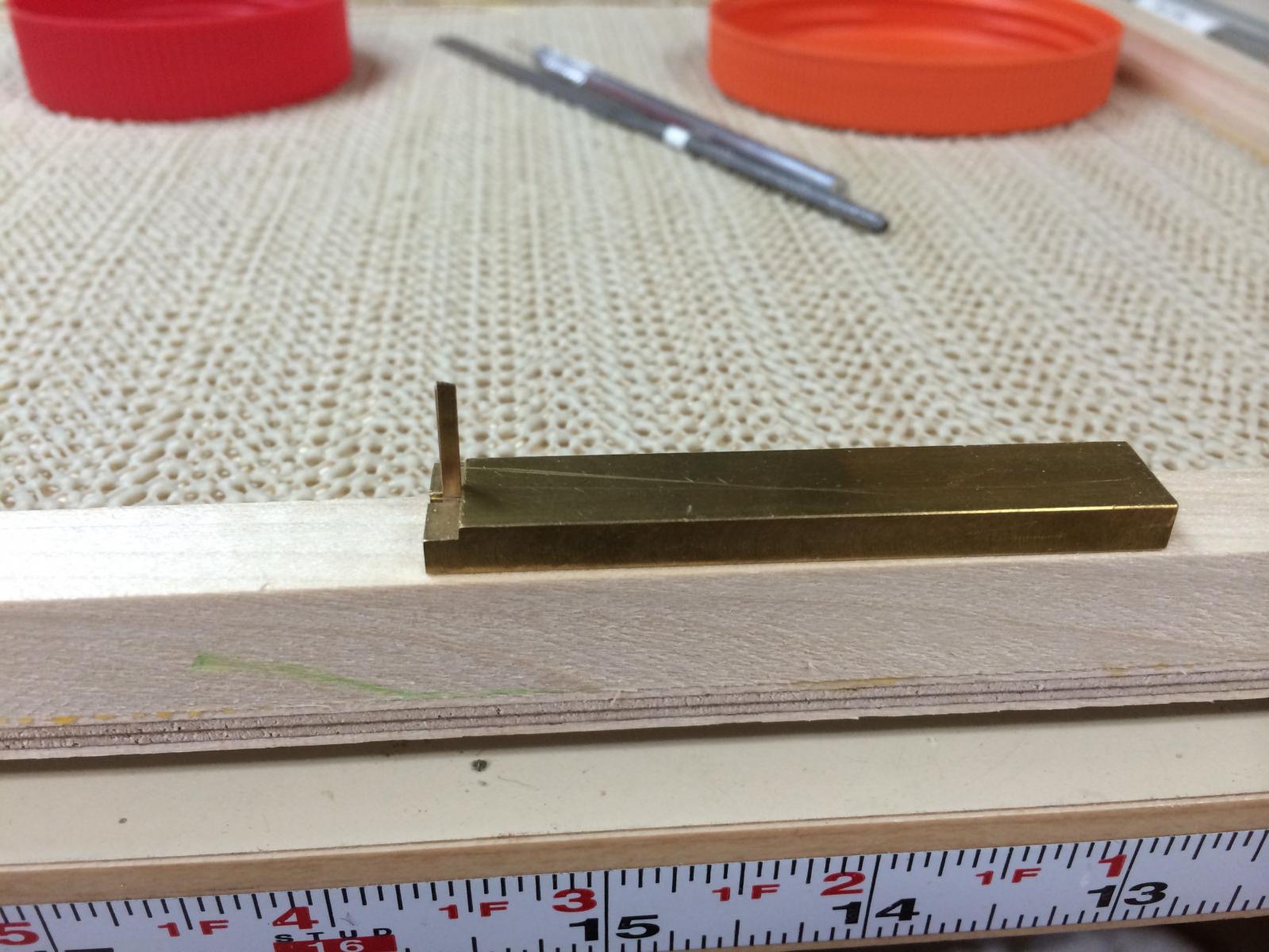
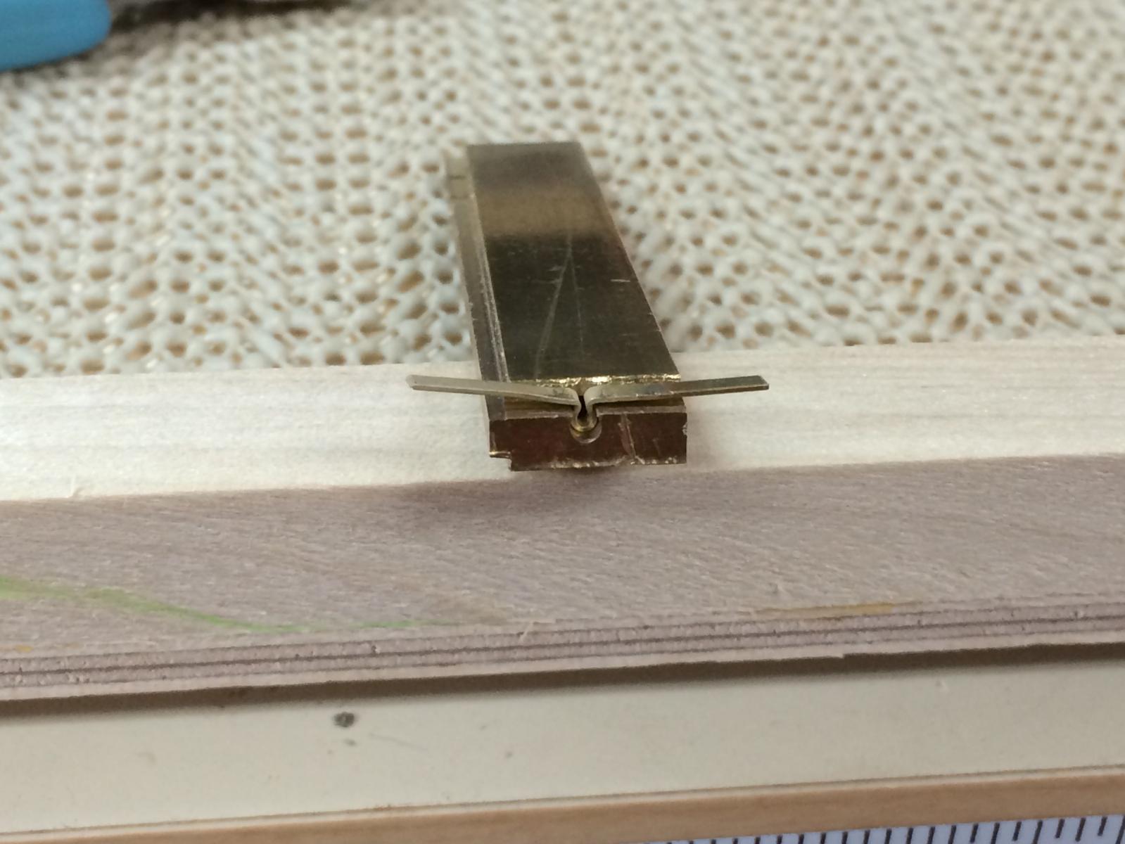
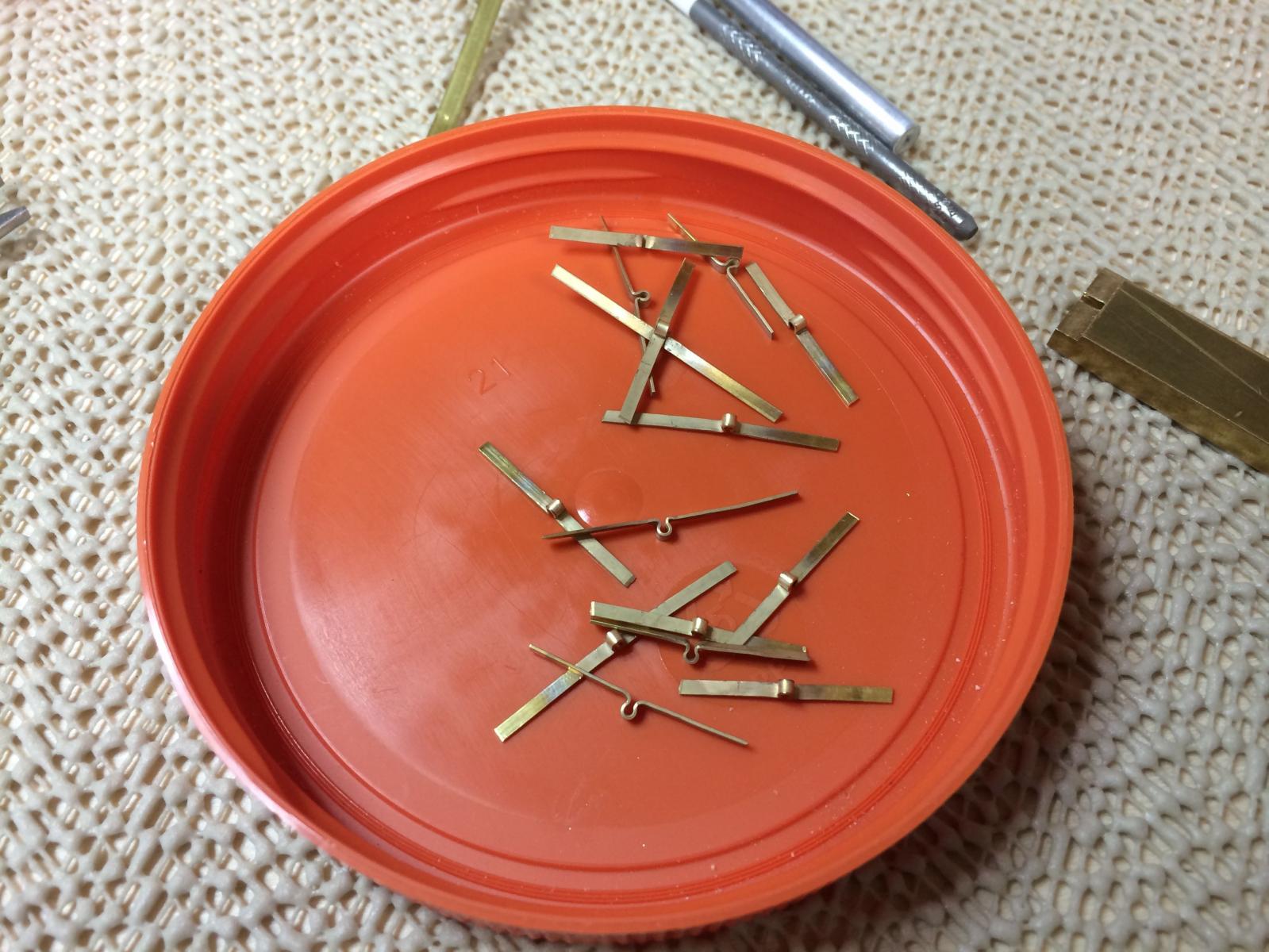
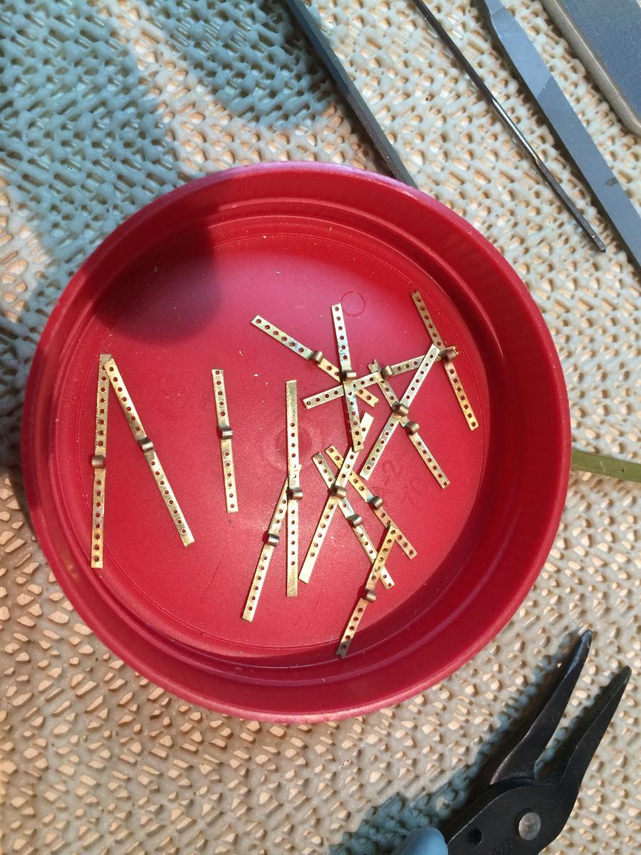
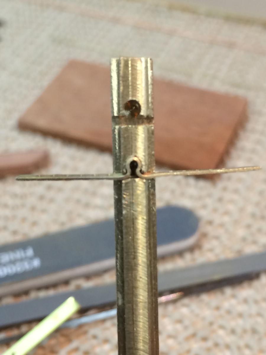
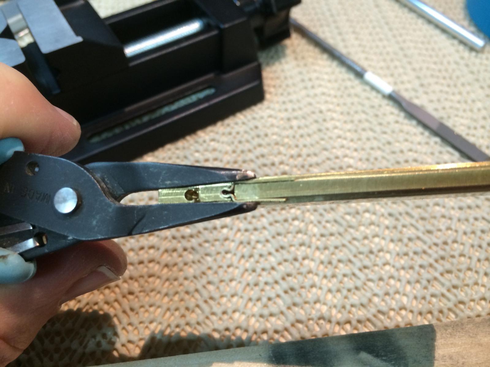
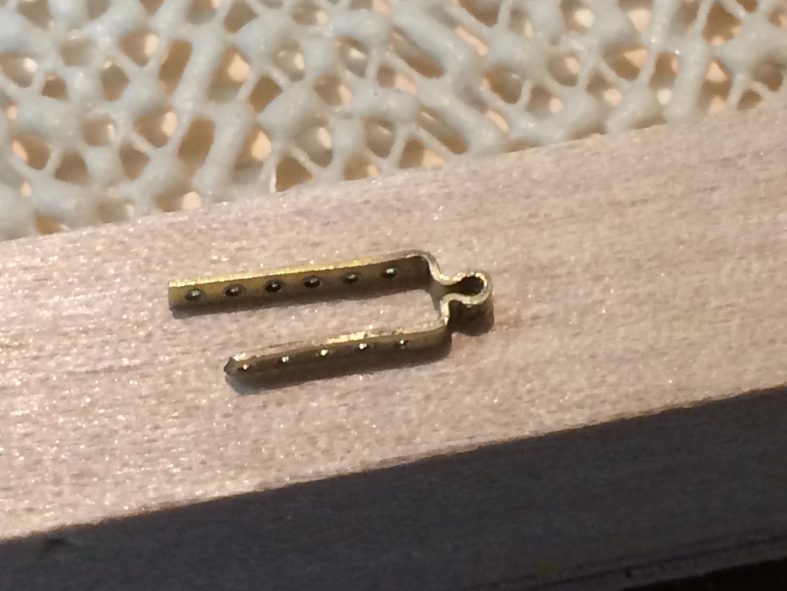
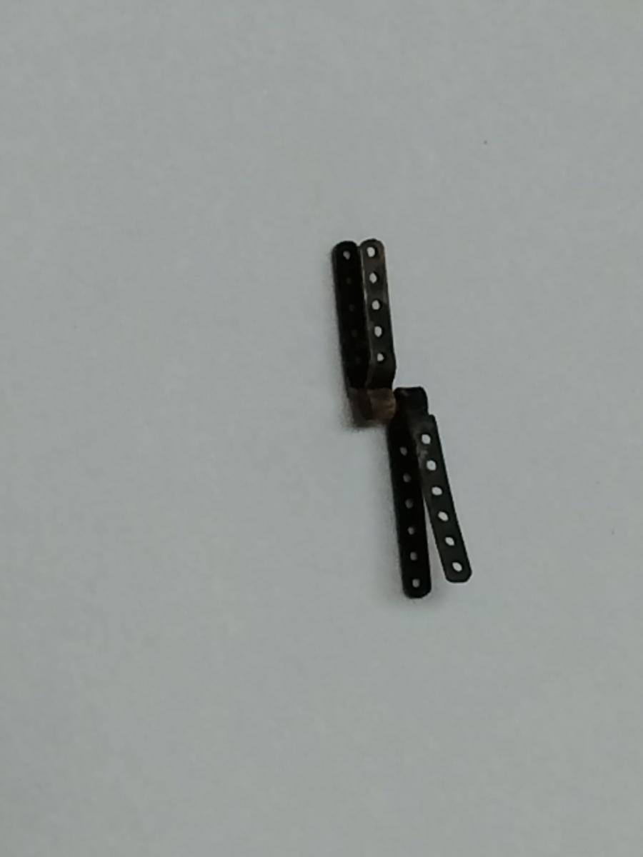
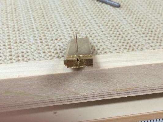
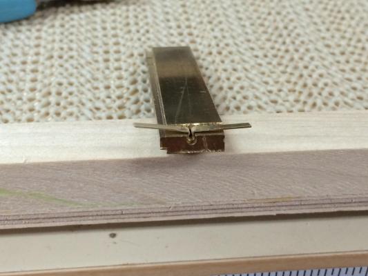
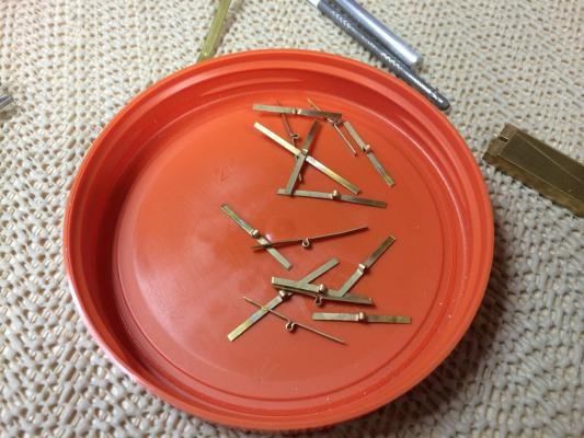
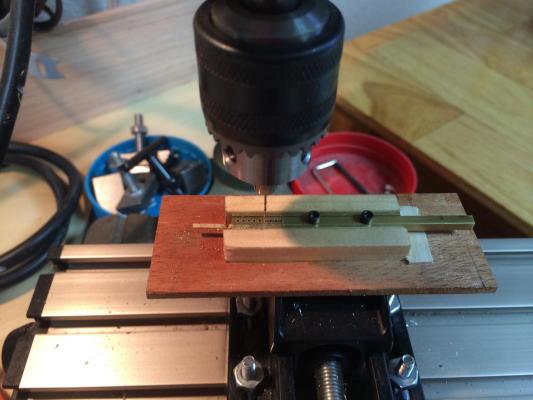
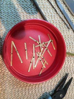
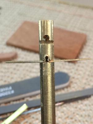
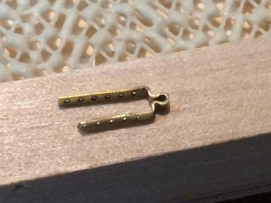
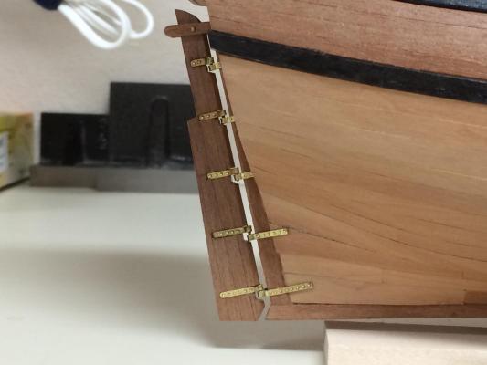
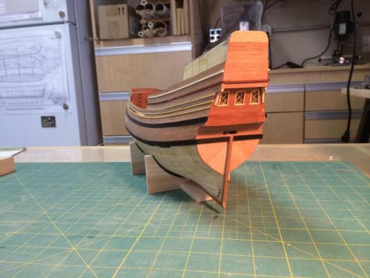
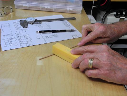
Paragon – a Modified Mayflower Part 11– Rudder and Rudder Hardware The rudder did not need to be tapered, so constructing it was fairly straightforward. I glued 4 pieces of 1/8 x 1/8 square African Pear stock together, and then cut out the rudder according to the plans. I darkened the PVA glue by adding some burnt umber acrylic artist’s paint to it, so that the joins in the rudder would be more noticeable. Again, I neglected to take any photos of the process, but the following photo of the completed rudder shows the effect of the darkened glue. Making the hardware, the pintels and gudgeons, was much more complex. I wanted to make them from brass, and if at all possible I wanted the hardware to work. My initial attempts consisted of trying to bend the brass strips using my vise and pliers. Some were satisfactory, while many were rejected. Even those that were satisfactory were inconsistent and when taken together didn’t look very good. I saw an idea in an MSW build log for making a wooden jig that would allow bending the brass at a good angle. Using that idea, I milled a jig from heavy brass stock that would allow me to make hardware that was consistent. My process was as follows: First, I annealed the brass strip, then bend it around a brass rod that was the same size as the intended pintel. Then I placed this into the first stage of the jig, which has a hole for the loop made in the prior step, and a ledge to keep the strip straight while being bent. Then the arms were bent to a horizontal position I made enough pieces to form the pintels and gudgeons (and lots of extras) I wanted to be able to mount the pintels and gudgeons using brass rods as pins, so the next step is drilling the holes for these pins before final shaping of the hardware. I wanted to have a method for drilling uniform holes, so I devised the following jig: The bottom piece has a channel within a channel. The larger channel is for the top piece of the jig to fit in, and the smaller channel is for the brass strip for the hardware to fit in. The holes in the top piece are one drill size larger than the drill used to drill the actual holes in the hardware. The holes in the bottom are several drill sizes larger and go all the way through the bottom to allow for clearing out the swarf and to prevent the drill bit from jamming and breaking when the jig is being used (I learned this the hard way and had to make a second jig). The two pieces of the jig are held together with 4-40 set screws. In use, the set screws are loosened, the brass strip is slid into the jig until the curved piece stops against the jig, then the set screws are tightened. The jig with the brass strip inserted are then placed on another wooden jig that is held in the drilling vise. This wooden jig holds the drilling jig loosely, so that the drilling jig can be manually adjusted so that the drill centers itself once the drilling starts. This combination of jigs allowed me to drill the holes with consistent spacing. The brass strip was then inserted into the original jig, in a second position. This position was made by drilling a hole the correct size for the bent part of the strip, and then using a slitting saw to make a slit the correct size to hold the flat part of the brass strip. A groove was cut on each side of the jig to allow the arms of the pintel/gudgeon to be bent to the correct size. The resulting pieces could then be cut to the correct length and final shaping was performed. The following photo shows a piece before trimming and shaping. The pintels (small brass rods) were soldered to the part of the hinge that would be attached to the rudder, and then each hinge was attached to the rudder and to the hull with brass rods. These rods were then nipped off with straight clippers, and the small ends that were left proud of the hardware give the impression of bolt heads. The brass jigs were made on my Sherline milling machine, and were my first complex pieces made on that machine. Consequently I learned a lot about a very valuable tool. A pleasant result of using the drilling jig was that the drilled mounting holes lined up so well that each mounting pin went all the way through the rudder and lined up perfectly with the holes on each side of the rudder. Before mounting the brass hinges on the ship I blackened them but was not pleased with the results. (Instead of brushing on the blackening agent I put the hinges in a bath of the agent – big mistake) I used a product from JAX (Instant Brass and Copper Cleaner) to remove the blackening, intending to try blackening again, this time by brushing it on. However, the cleaner removed not only the blackening but the residue and discoloration from the soldering, and I really liked the way the brass hardware looked, so I mounted it as is. Making the rudder, the rudder hinges, and installing the rudder took several weeks, and there were lots of ‘do-overs’, but it was a great learning experience. Next is another learning experience – making the Beakhead.


-
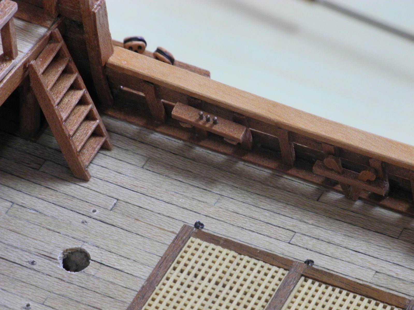
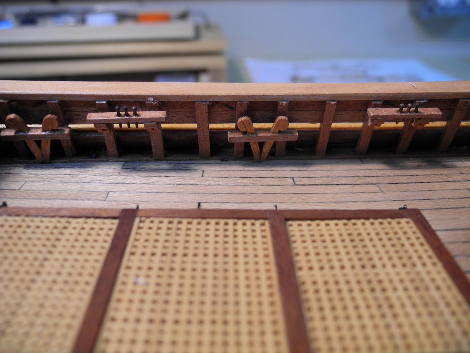
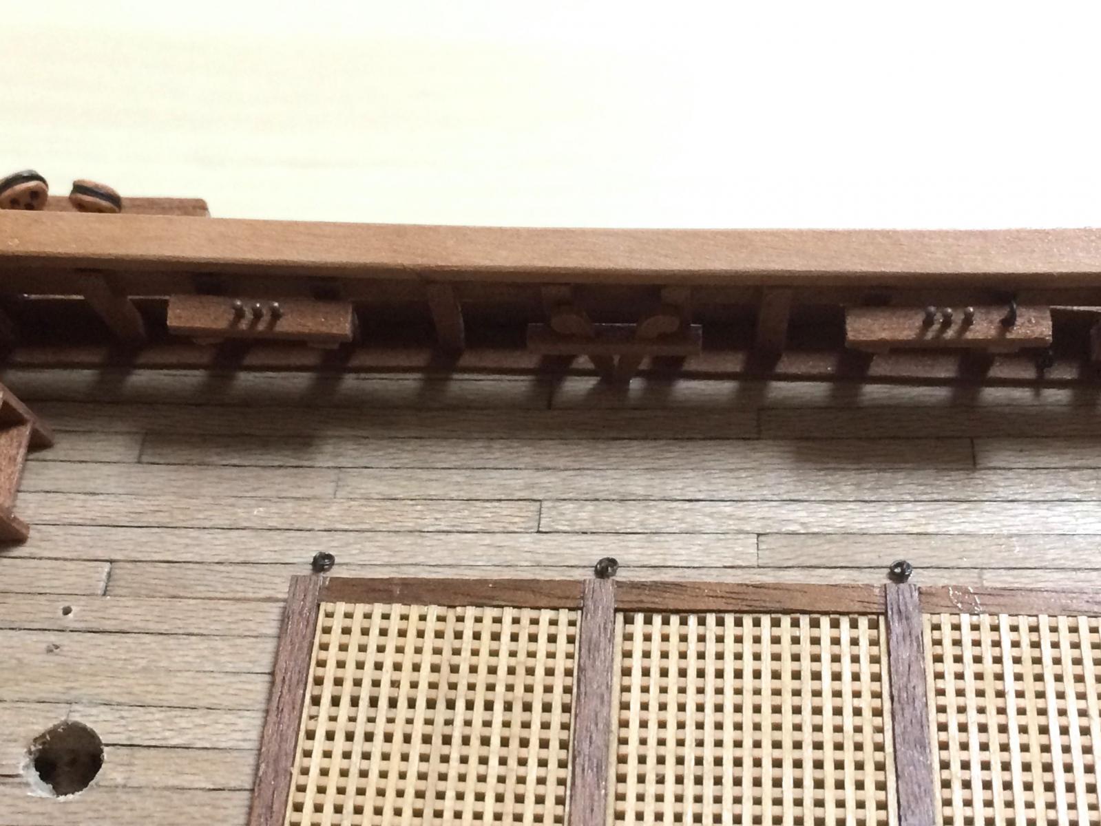
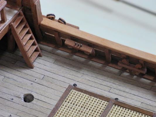
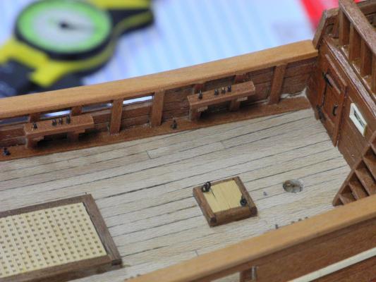
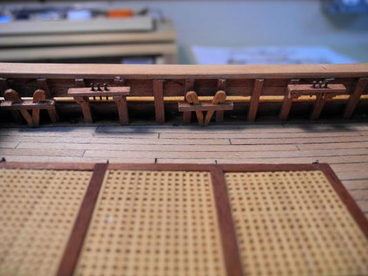
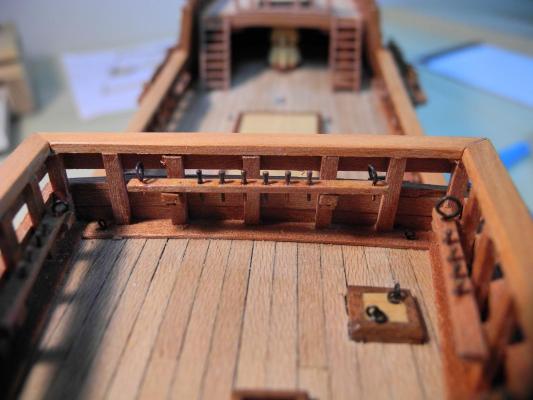
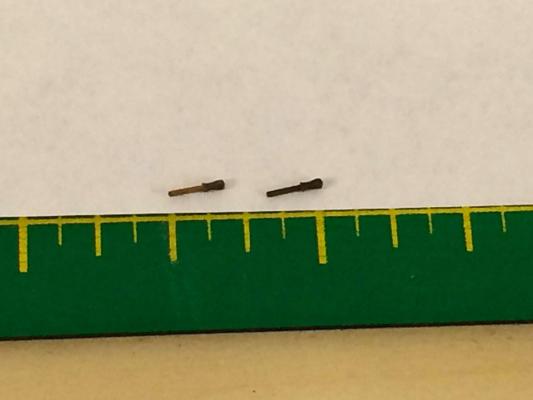
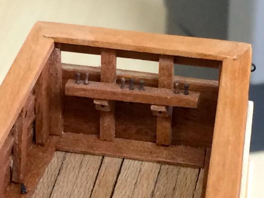
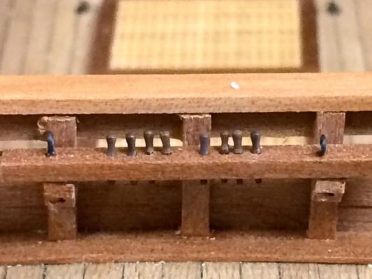
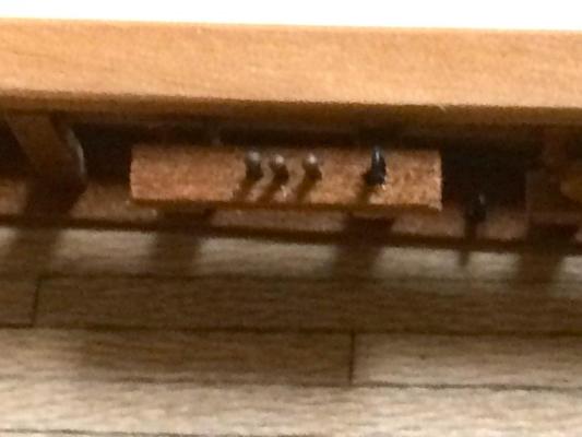
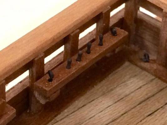
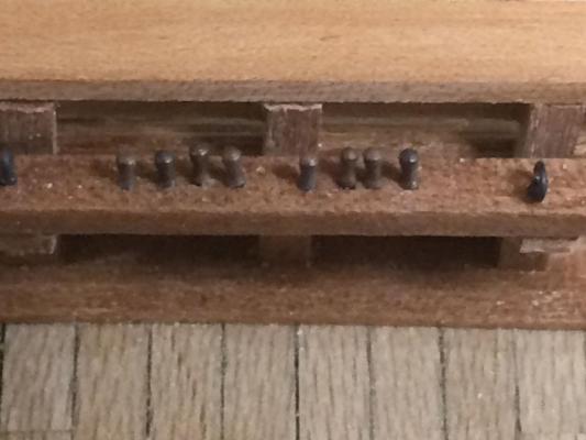
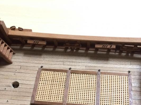
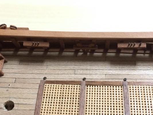
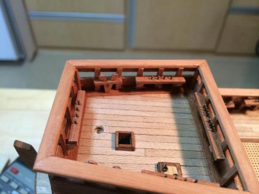
OK - I finished the new Pin Rails and installed them. To make the pin rails I used some wood strips that were 3/32 wide and 1/16 thick. I marked and drilled the holes for several pin rails in one long strip, then put the strip through the thickness sander until it was down to .045 inch. I drilled the holes first because I knew it would be difficult to hold the thinner strip in the milling vise. I then cut the strip into the appropriate lengths for the pin rails. Here are some photos of the way they look now: So, I need to thank a few folks for helping me catch this error: First, Mark - thanks for pointing this out. This is the real value of a build log, when another modeler sees something that isn't quite right and has the confidence to say so. Second, Bob and Brian - you've both urged me to post a build log and for the longest time I put it off for several reasons. Now I'm glad I finally got around to it, because without it I know I would have been struggling with tying off the rigging at the pin rails. I think I'm in much better circumstances now.
-
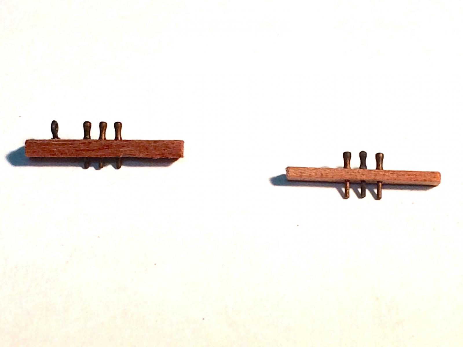
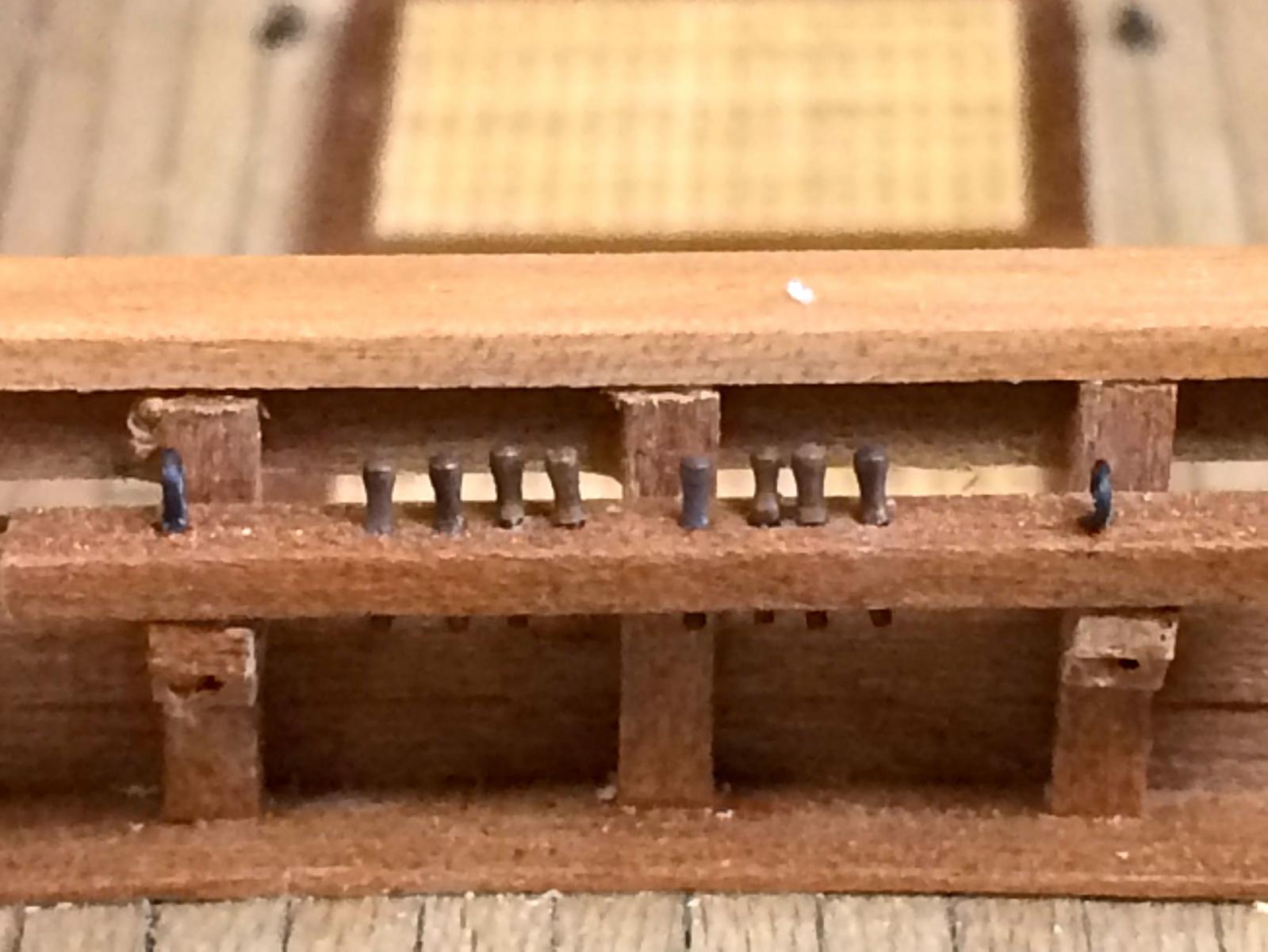
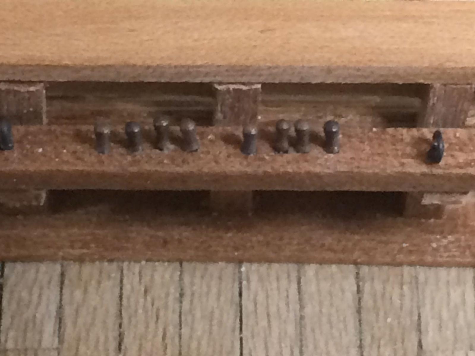
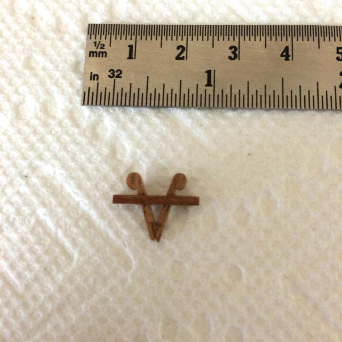
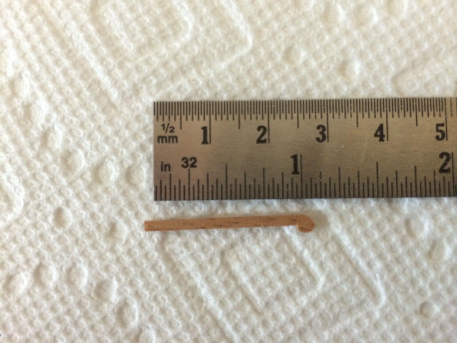
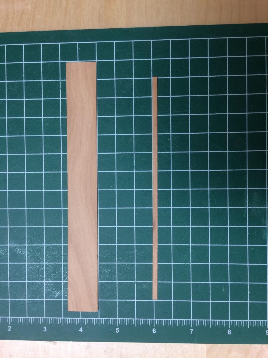
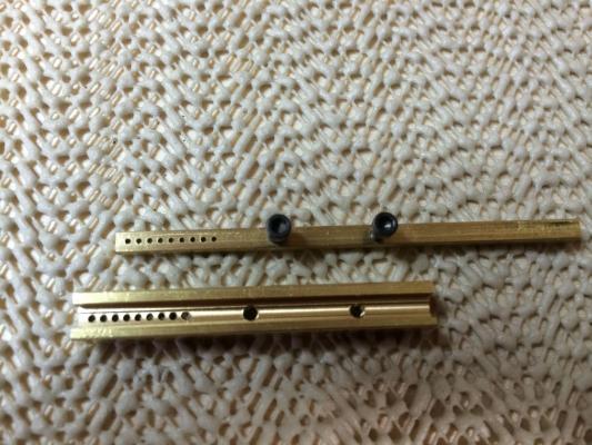
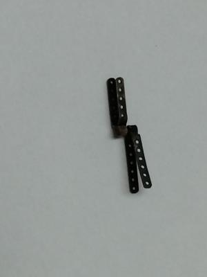
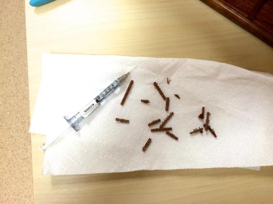
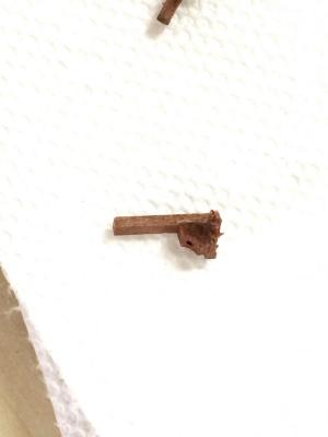
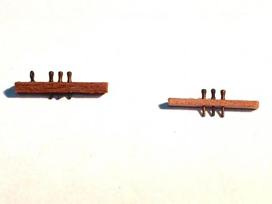
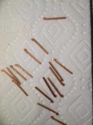
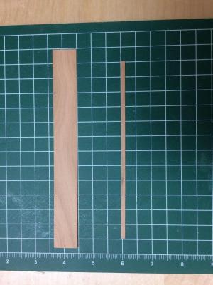
Hi Brian, Bob, and Mark After thinking some more about the pin rails, I decided to go ahead change them. The old pin rails, being so thick, left very little pin sticking out of the bottom of the pin rail. This would definitely cause some major headaches during rigging, so it's probably better to spend the time changing them out. I used iso alcohol in a syringe with a very fine blunt needle to put the alcohol only where I needed it. After letting it soak into the pin rails for a minute or two, I was able to pull the pin rails off their supports. Most of the pin rails came off fairly easily. Some of the supports came with them. One of the things I was worried about was breaking a stanchion that a pin rail was attached to. This did indeed happen, but only one stanchion. The old pin rails were 1/8 wide and 1/16 thick, with the pins in the center of the rail. I made the new pin rails 3/32 wide and .045 thick (slightly less than 3/64), and I also positioned the pins so that they are closer to the front - approximately 1/32 from the front edge. The smaller width will allow me to position the pin rails so that there is a slight gap between the pin rail and the stanchion. This may come in handy during some of the rigging. In the following photo, an old pin rail is on the left and a new one is on the right. The pins are 1/16" apart from each other. This gives a pleasing appearance, but doesn't give much room for lines going to adjacent pins. I've looked at the rigging plan, and there really aren't a lot of cases where this will be a problem, since most of the pins will be empty (since there are no sails the running rigging is much simplified). In the case where there are adjacent lines, I will design the pin rail so that there's more room between the pins. I'm going to keep working on this today until I get it completed (hopefully), then I'll post some photos of the new pin rails in place. Mark - thanks for bringing this up. It caused a little rework, but it will be well worth it.
-
Hi Bob: The scale is 1:77, so 1/16 thick is almost 5 inches actual, which is too thick. I probably should have made the pin rails 3/64, which would have been about 3.5 inches. I think the depth of the pins in the rail - they're centered on a 3/32 rail - is also going to be a little bit of a problem. All that being said, I just don't want to rip it and and do it over, so I'm going to have to deal with it.
-
Thanks Mark. I checked as you suggested, and the pin rails are too thick. I did follow the specifications for the kit, but perhaps the belaying pins for the kit were larger (and out of scale). I could probably rip them out and correct the size of the pin rails, but I don't want to prolong this build so I'll find a way to deal with it. This is, after all, a learning experience - and I've learned a lot so far.
-
Lots of other strange things to look at on Paragon, as well. Will you be bringing my new camera?
-
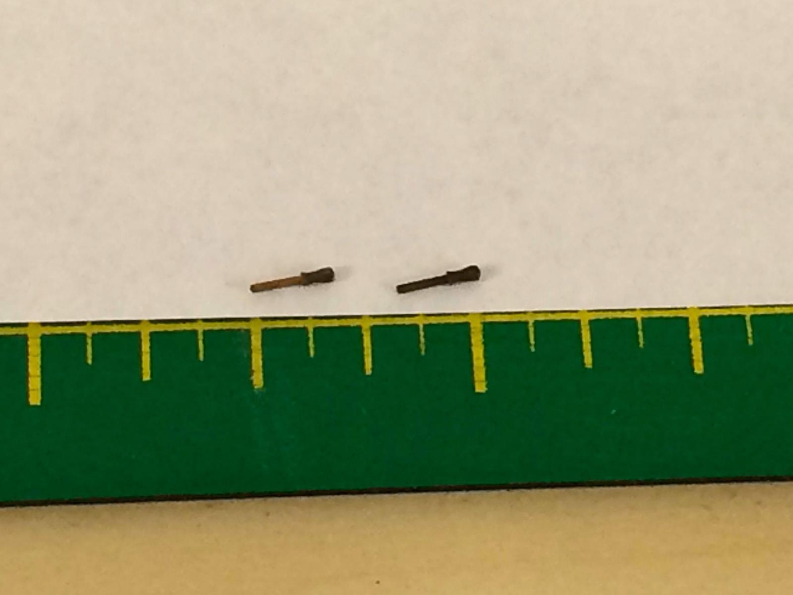
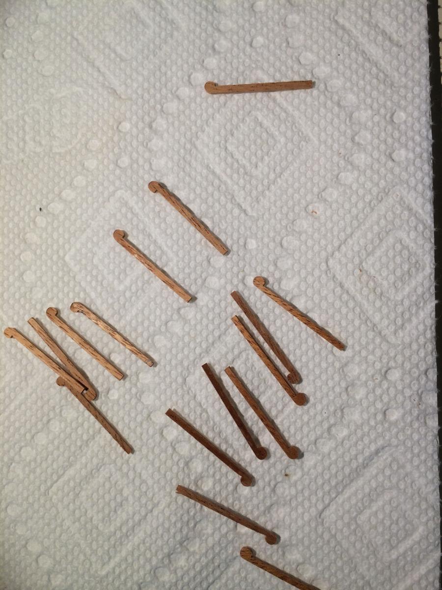
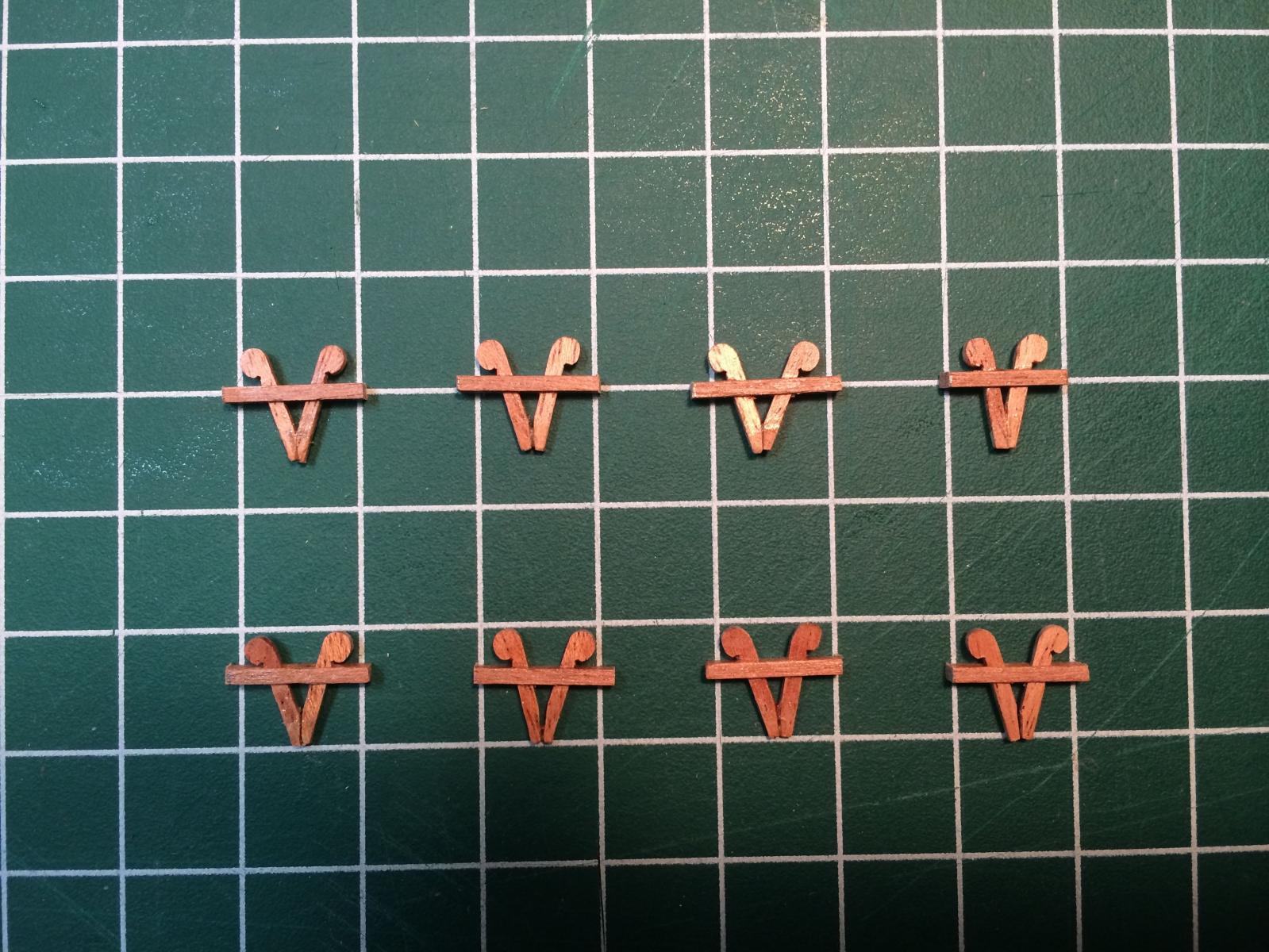
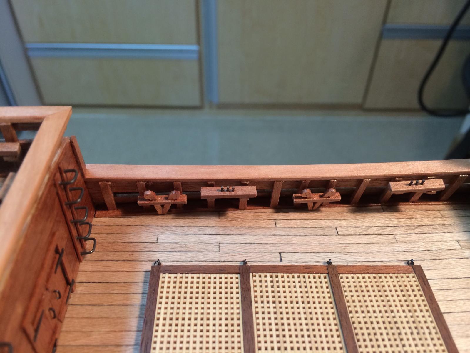
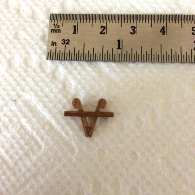
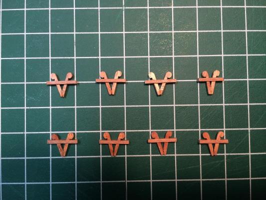
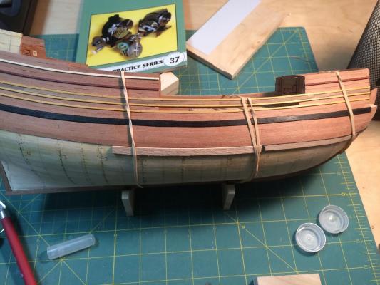
Paragon – a Modified Mayflower Part 10– Pin Rails and Kevels When I decided to build the Paragon as my first scratch build, I also made the decision that I would not purchase any components for the ship, but would make everything myself. Well, that lofty goal lasted until I reached the point that I needed belaying pins. At the scale of the model, 14” belaying pins would only be 3/16”. I do have a Sherline lathe, and I guess with enough trial and error I could learn to produce the belaying pins I needed, but I don’t want this to be the only model I scratch build during my lifetime. Model Expo had some 3/16” belaying pins that I could buy, so that saved me quite a bit of work. The pins are nicely shaped, and once blackened they served my needs well. (The photos of the belaying pins and the pin rails leave a lot to be desired, and I apologize. Once Brian gets me my new camera I’m sure the photography will improve. ) Making the pin rails was pretty straightforward. I made them out of stock 1/8 wide and 1/16 thick, and cut the lengths to conform to the number of stanchions they would need to cross. I made brackets out of 1/8 x 1/8 stock for holding the rails to the stanchions. The Kevels took a little more thought. I decided to make them according to the illustrations in the kit booklet – a v-shaped upright with a cross piece. Since there were 8 kevels in all, and I wanted to make them identical to each other, I decided to mass-produce the uprights using Ambroid glue. I started by gluing 16 pieces of 1/16 stock together. Once the glue was set, I shaped the grouping to the profile of an upright – essentially a straight length of wood with a curved knob on one end. When shaping was done I soaked the grouping in a bath of acetone, which separated the grouping into the 16 individual parts. The cross pieces were made of stock 1/8 wide by 1/16 thick. I milled a slot in each cross piece to allow the 1/16 uprights to fit in the slot, then assembled the kevels. I was pretty happy with the results. Next is fashioning the rudder and its hardware.


-
Hi Ron - just found your log, and appreciate all the research you put in. I also have the Kathryn documentation from HAER, and hope to scratch build her one day.
-
Very nice work, Hartmut. I'll be following your build with great interest.
-
I agree on the Woodslicer. I have a 14" Rockwell (over 60 yrs old) and keep the 1/2" Woodslicer blade on it.
-
Hi Brian - good thinking. Seems to me that you're ready to leap into the scratch-building side of the pool.
- 831 replies
-
- 4
-

-
- Armed Virginia Sloop
- Model Shipways
- (and 1 more)
-
Thanks folks. I won't be posting any more updates for a few days - have some commitments for the holiday weekend. Enjoy the weekend!
-
Pandora by marsalv - FINISHED - 1:52
Mahuna replied to marsalv's topic in - Build logs for subjects built 1751 - 1800
Hi Marsalv: I just found your log, and will be following along. Very nice work! -
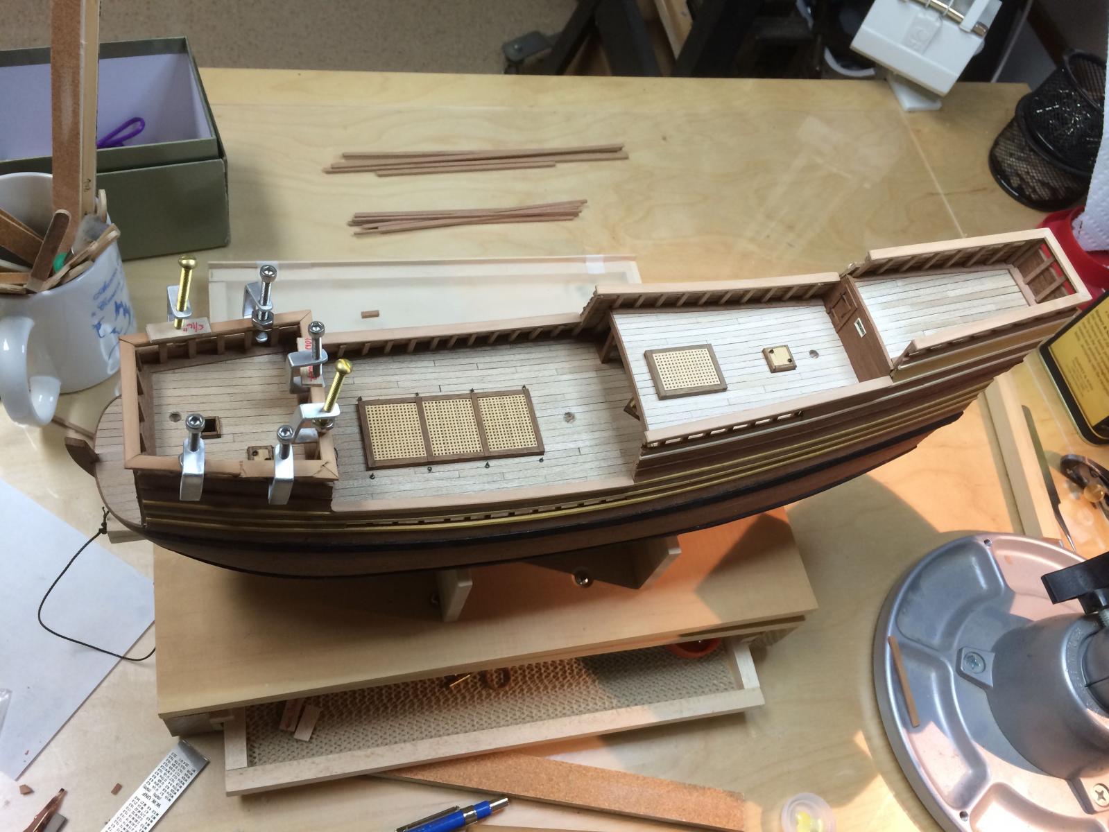
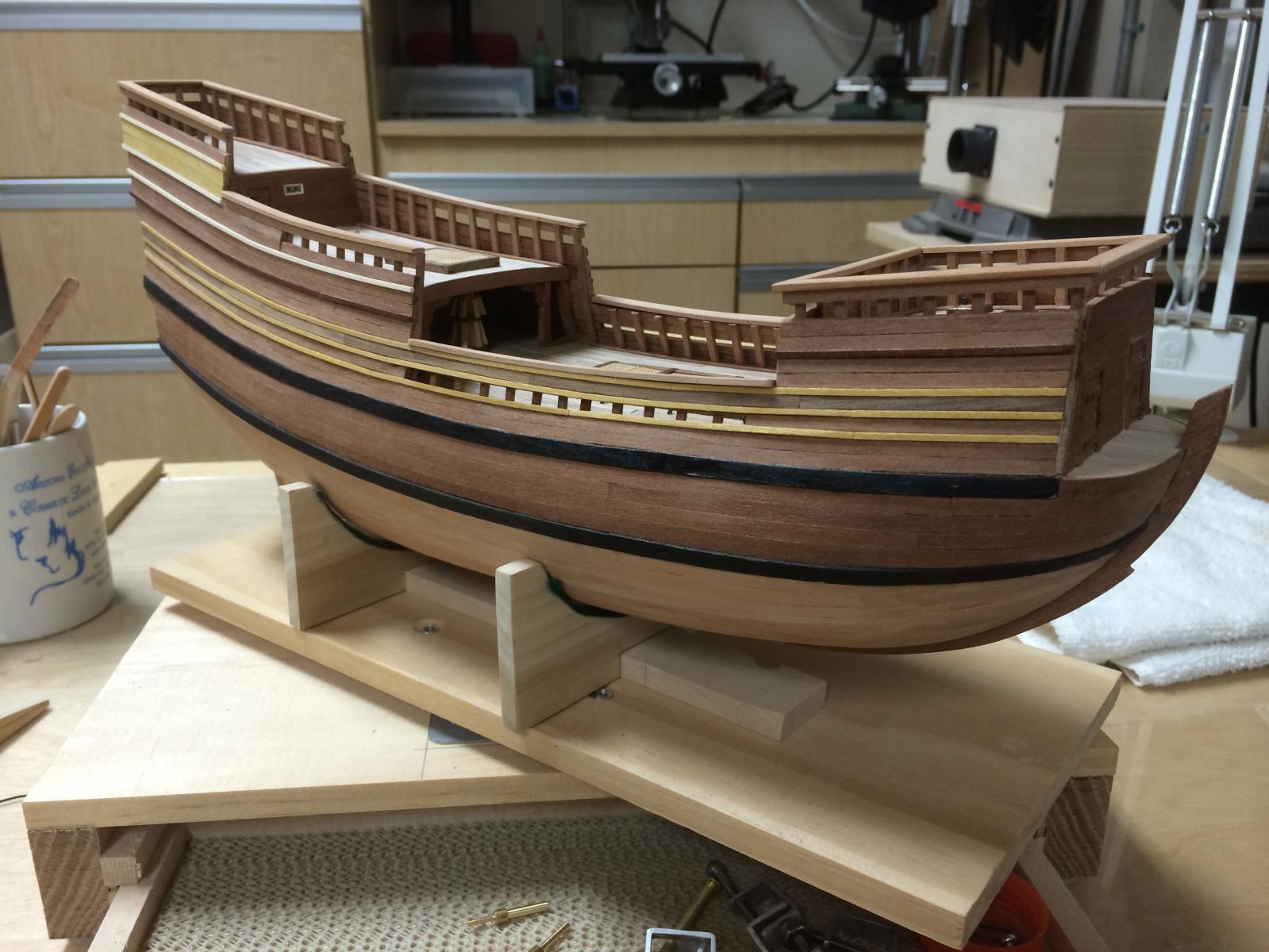
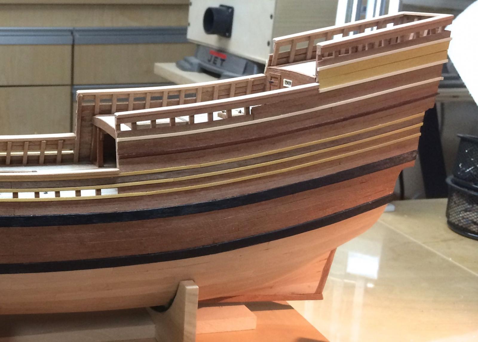
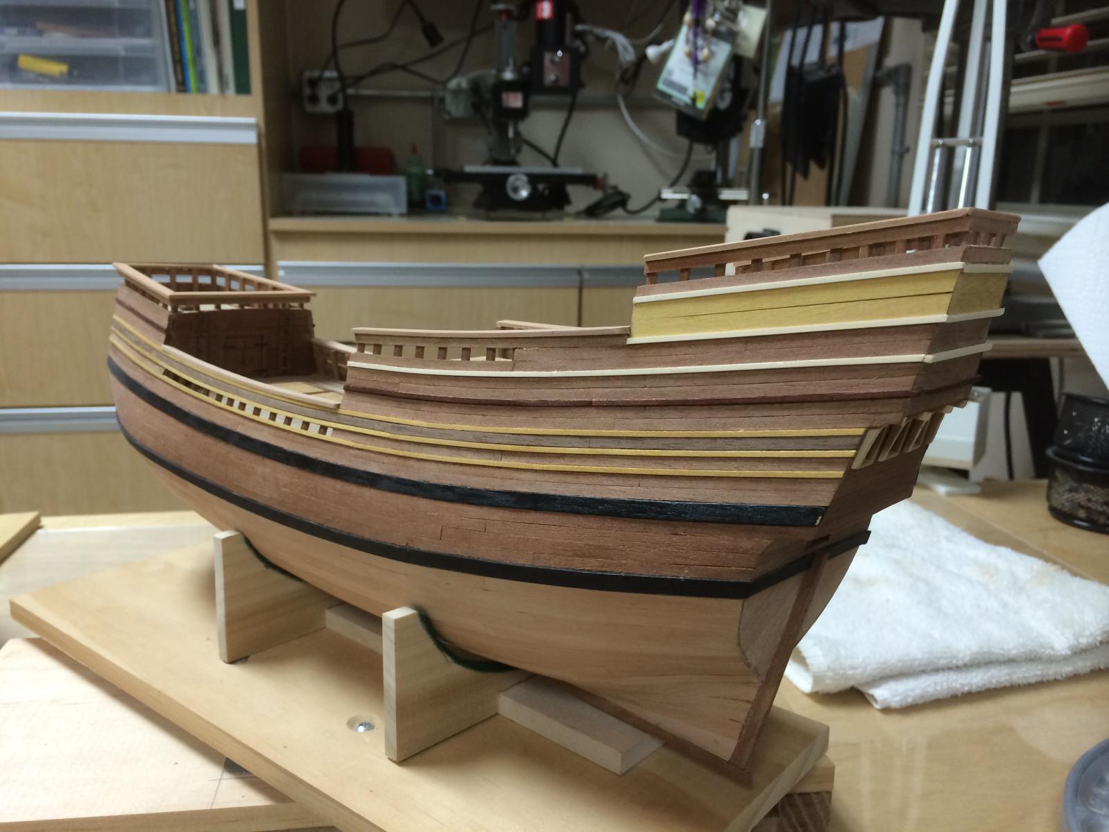
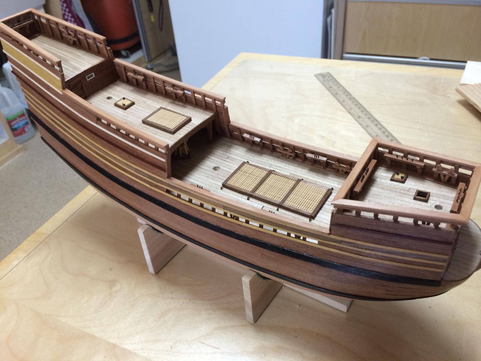
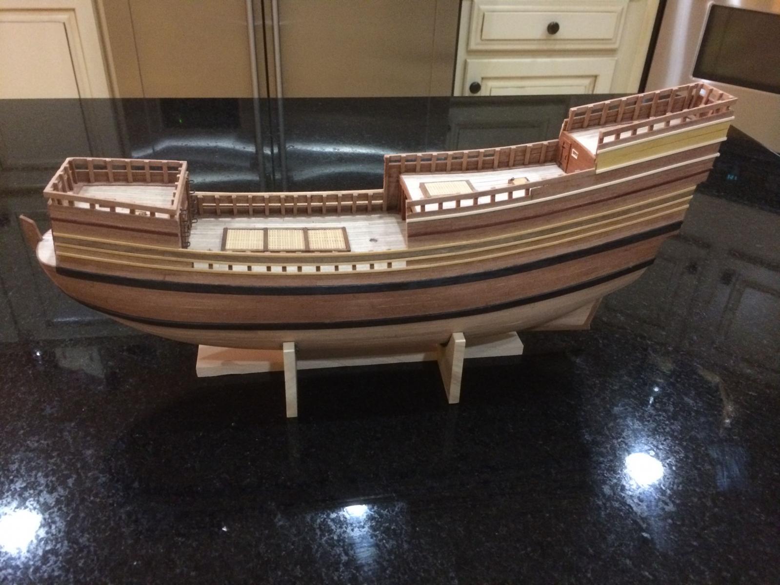
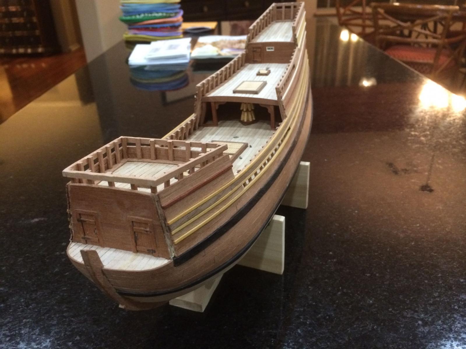
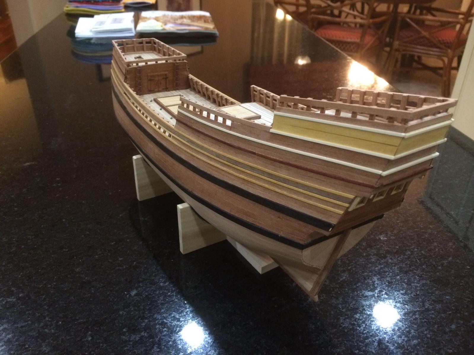
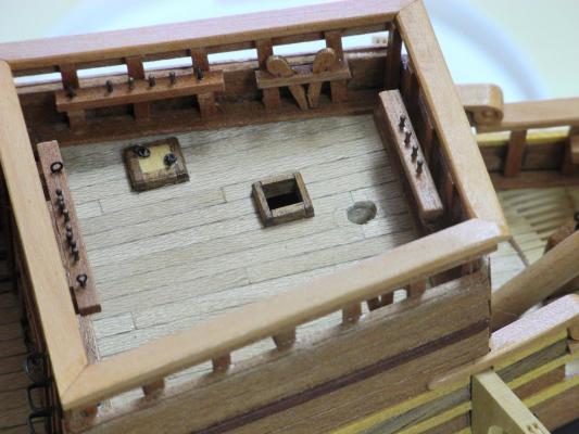
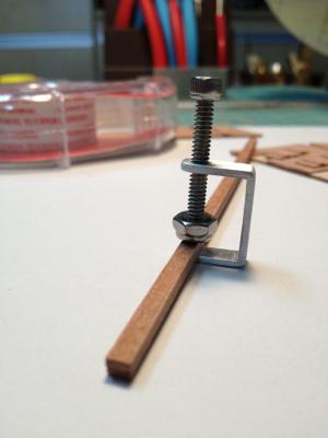
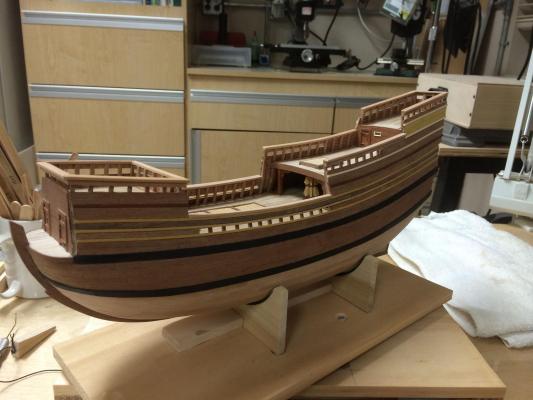
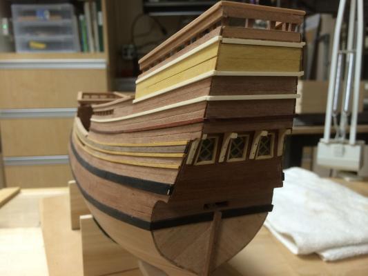
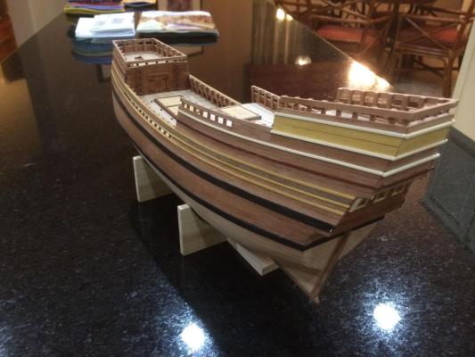
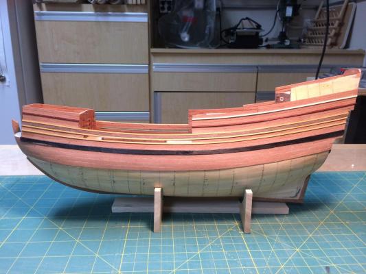
Paragon – a Modified Mayflower Part 9– Stanchions and Railings In the last post, I mentioned that I started the hull planking before I finished the planking in the Poop area, because I wasn’t sure what I wanted to do there. I had already planked the entire stern area with African Pear and a little bit of Madrone, without carrying any moldings around it, and it looked pretty bare to me. I decided to add some decorative planks and moldings to the top of the hull in the area of the poop deck, and to carry that effect around the stern. I thought that was more pleasing to the eye (don’t forget that I have lots of poetic license going here). From the upper wale, moving up, there are 3 moldings of 1/16 x 1/16 Yellowheart. There is a strake of Walnut between the second and third of these moldings. Then there is a molding of 1/16 x 1/16 Bloodwood between two double strakes of African Pear. The next molding is 1/16 x 1/16 Holly (I love this wood and wish I had used more of it on the ship). The decorative works on top consists of two double-width (1/4” width) strakes of Yellowheart bordered by Holly moldings. All of these moldings were carried around the stern, and I liked the effect much better. Most of the details (stanchions, pin rails, ladders, etc) were made of African Pear, in keeping with the tones of the ship. I wish I had discovered earlier how the African Pear tends to splinter. By the time I discovered that, it was too late to change. I used some polishing blocks used by nail technicians to try to smooth out the pear strips – it worked better than sandpaper, but still was not able to get a perfectly smooth finish. The stanchions are 1/16 x 3/32 strips of African Pear. I used a 1/8” strip as a spacer between stanchions. After the stanchions were installed, additional 1/8 x 1/16 planking needed to be added to form ‘railings’ and to complete the body shape. The result was pleasing to the eye, and could have been left as is. In fact, this is how the kit model is finished. However, the ship I was building needed real railings to conform to descriptions in the story line. There were parts of the ship built of ‘wizardwood’ that made the figurehead and the ship an integrated whole – the figurehead, the bottom of the ship, and the railings. I used the Madrone as the ‘wizardwood, therefore I needed to install Madrone railings around the ship. Long before I reached this point I had foreseen the need for miniature C clamps (and to be honest I just wanted to see if I could make them). I used 3/4'” Aluminum U channel to make the clamps. I drilled and tapped holes for 6-32 screw threads about 1/2 inch apart, then parted off slices slightly larger than 1/8 inch. After filing the edges and sides to get rid of any jagged pieces I inserted 6-32 x 1 inch socket cap screws into the threaded hole, then added a nylon lock nut to the screw. These clamps wound up being perfect for holding the Madrone railings while the glue set. I mitered the corners of the railings, but needed to make adjustments to allow for the fact that the corners were not perfect squares. Overall I’m very pleased with the effect, even though the railings are somewhat larger than scale would indicate, and I think the railings add a nice finishing touch to the ship. Next up: Pinrails and Kevels


-
Brian - if you want to get me a better camera I'd be happy to take it! Patrick - thanks for continuing to look in - it means a lot. Bob - yeah, making tools and jigs is a big part of what I enjoy about the hobby.
-
Hi Ed: I really like the concept of using the hold-down bolts, but I'm having a hard time envisioning when you will actually secure the ship to its base. It seems that most of your work is done on your shipway (and secured to the shipway via the hold-down bolts?), and it strikes me that it would be difficult and dangerous to the model to attach the bolts through base and model when the model is nearing completion. Can you say a few words on how and when you attach the model to the final base? Frank
- 191 replies
-
- 3
-
-
- young america
- clipper
- (and 1 more)
-
Very nice tutorial, Brian, and a well thought-out process too. I like what you did with the catheads - glad to see your getting lots of use out of the lathe already. Frank
- 831 replies
-
- 3
-
-
- Armed Virginia Sloop
- Model Shipways
- (and 1 more)
-
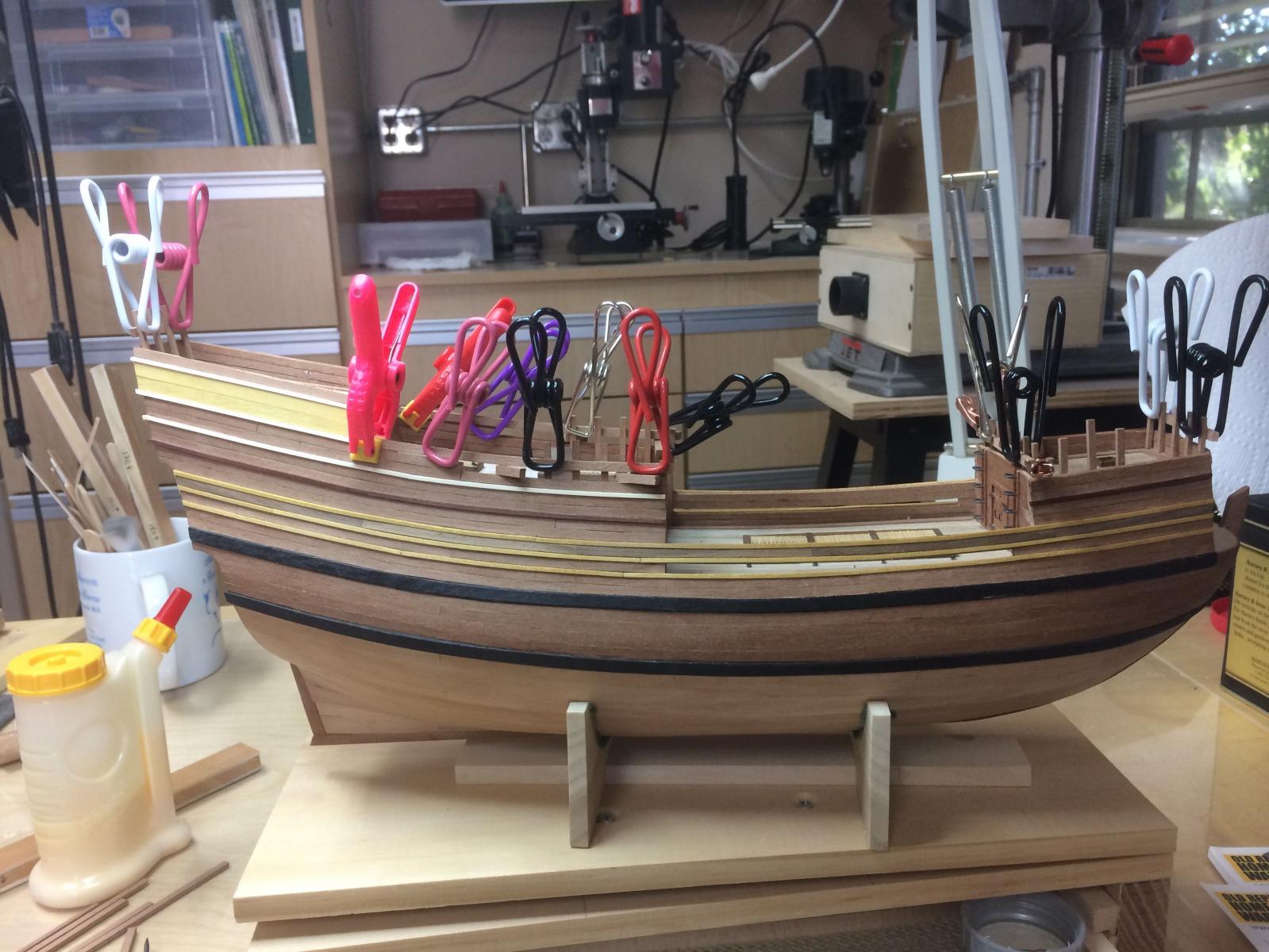
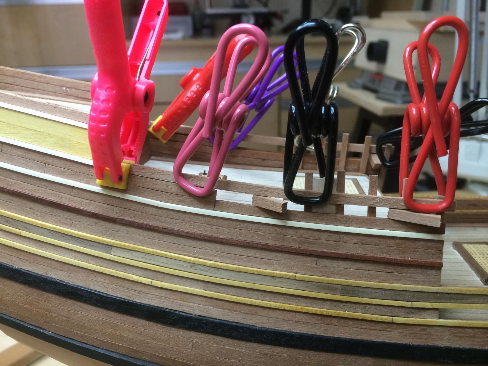
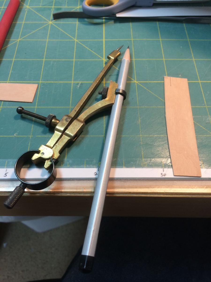
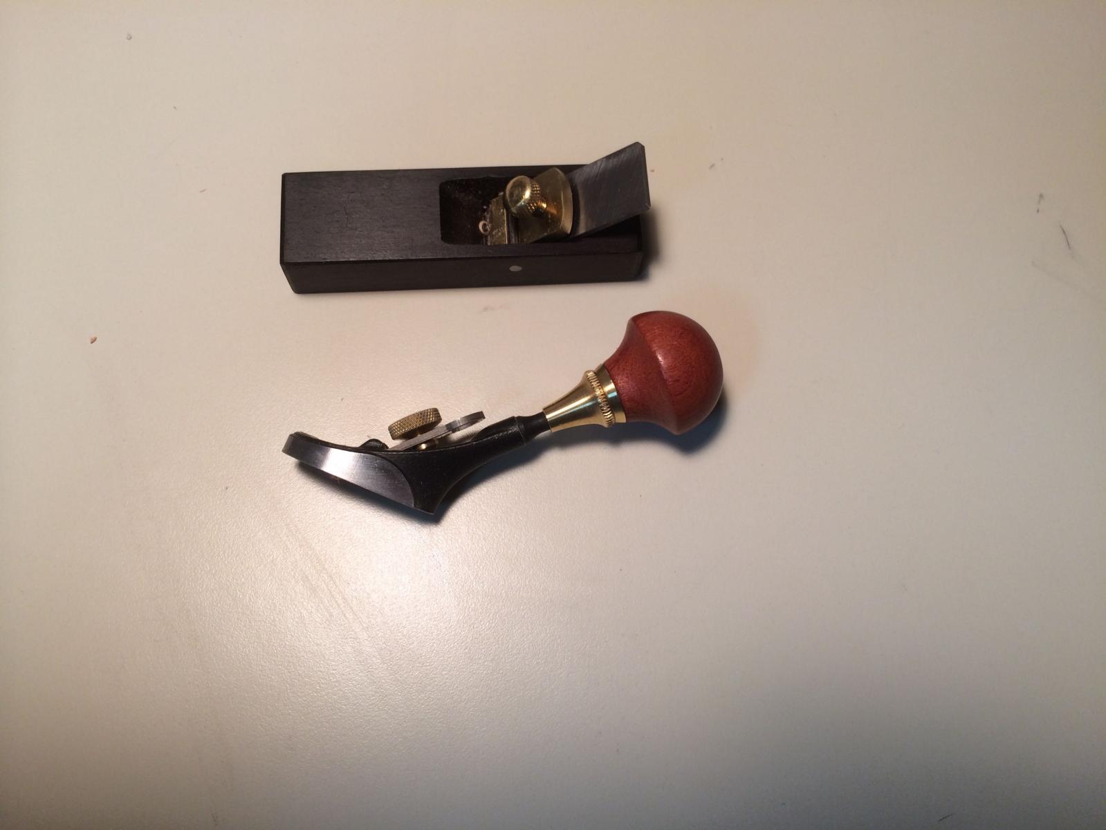
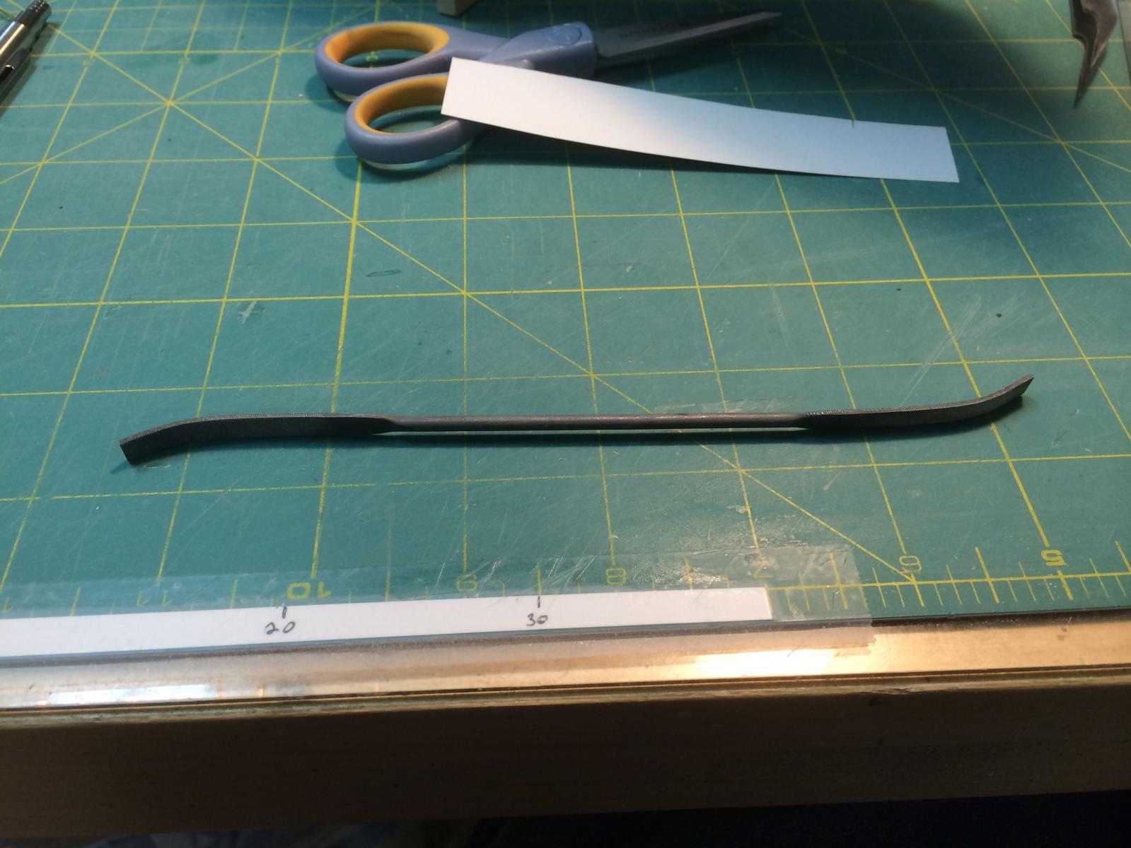
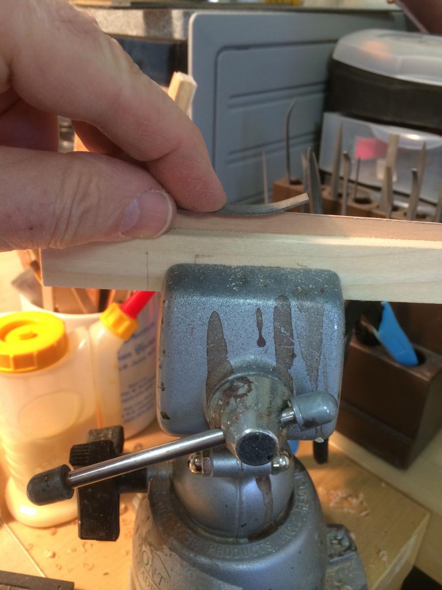
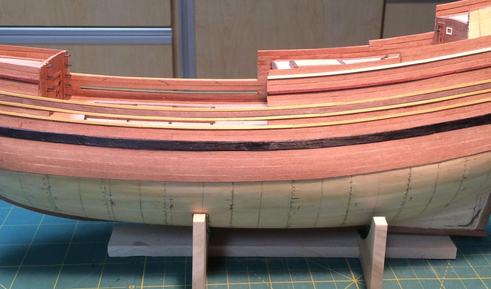
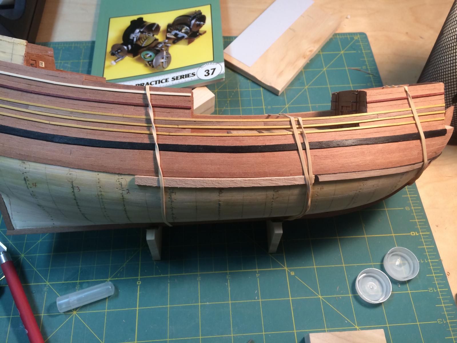
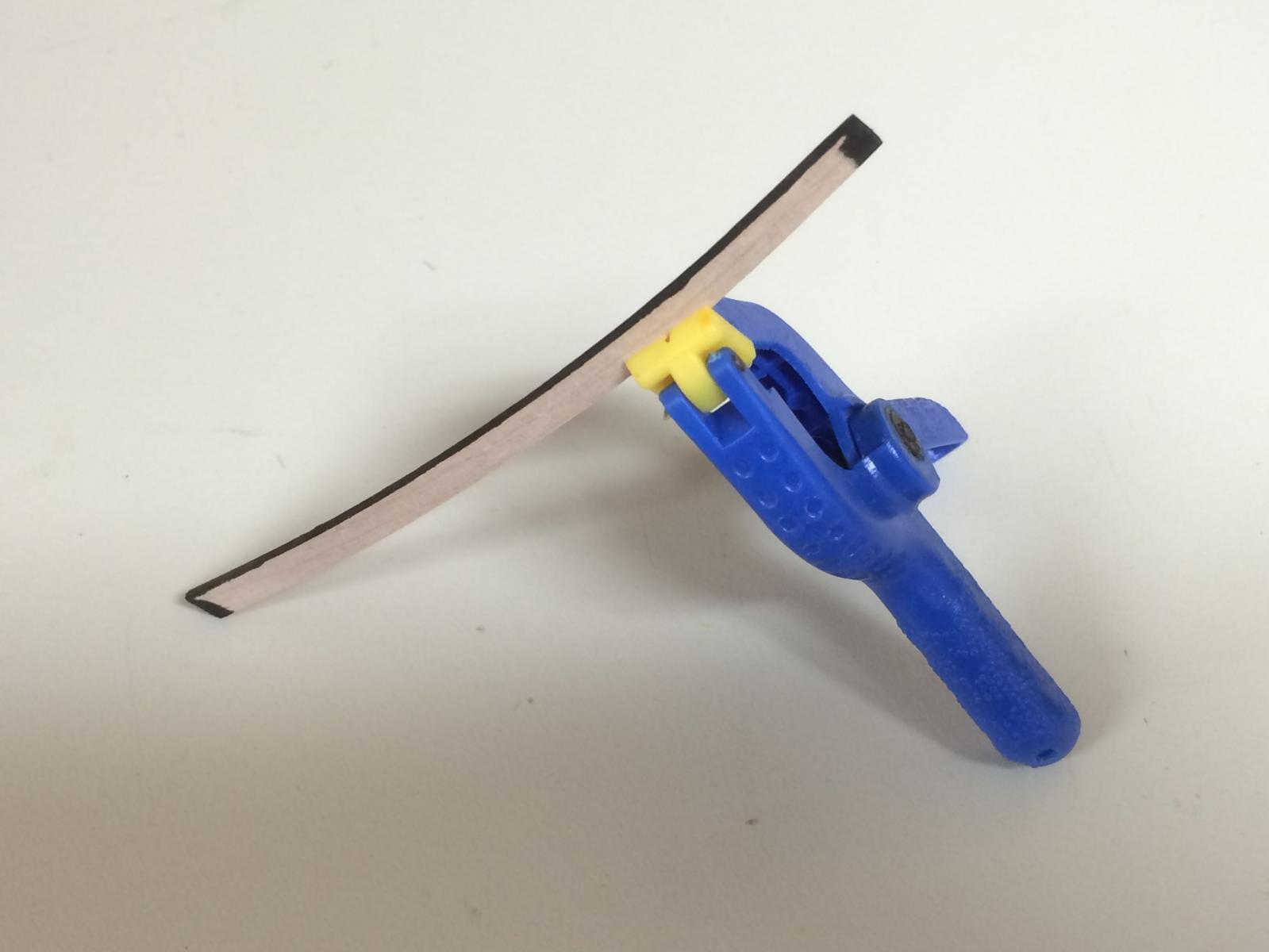
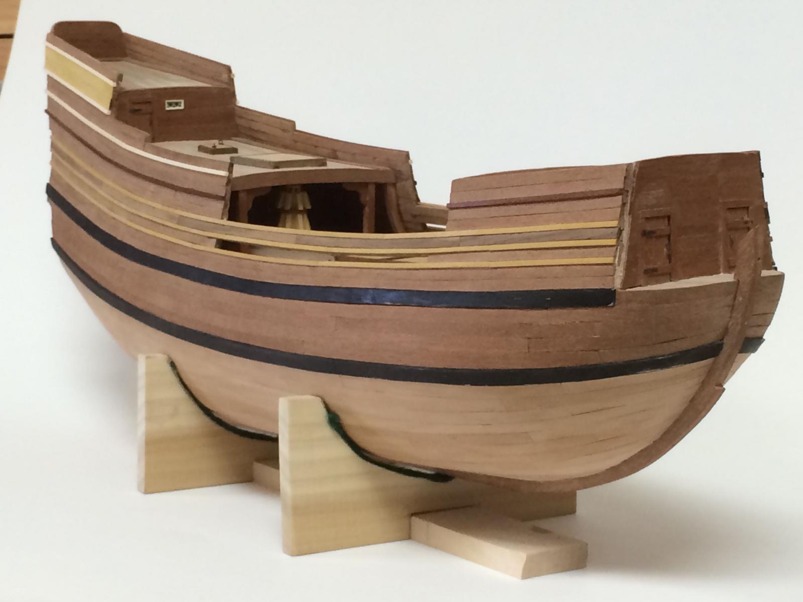
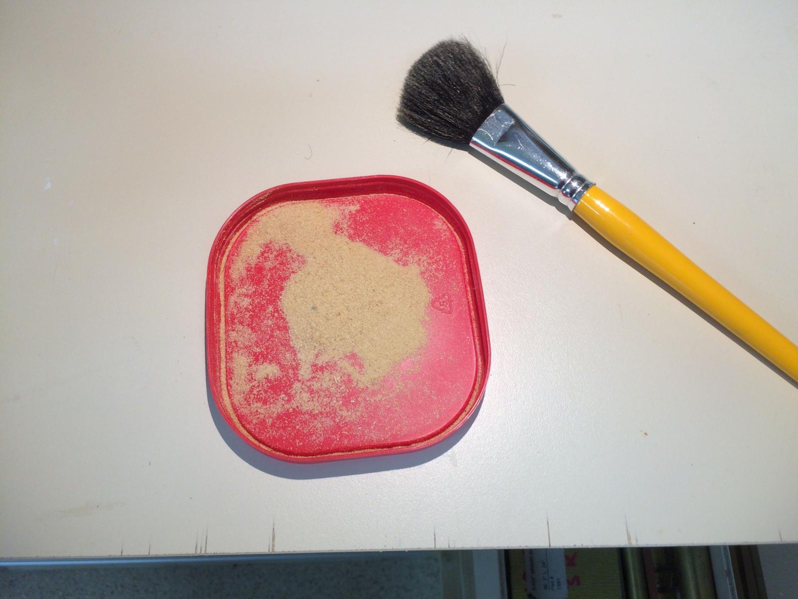
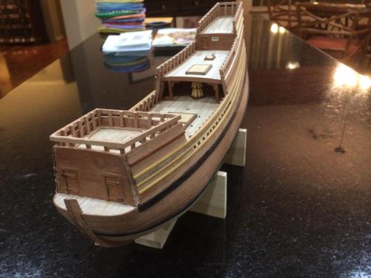
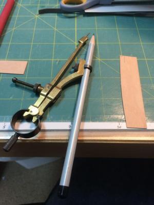
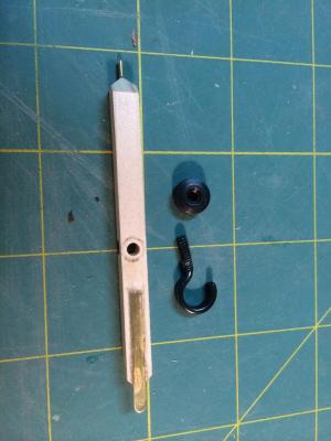
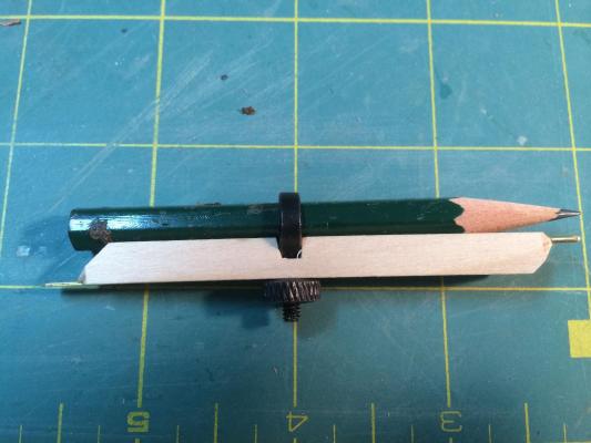
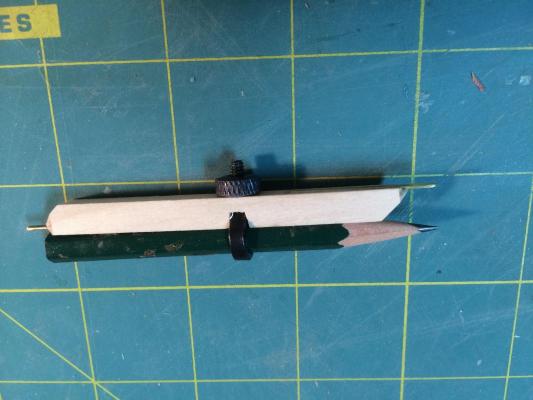
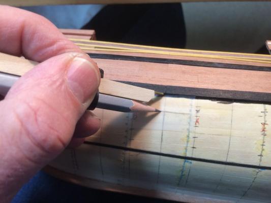
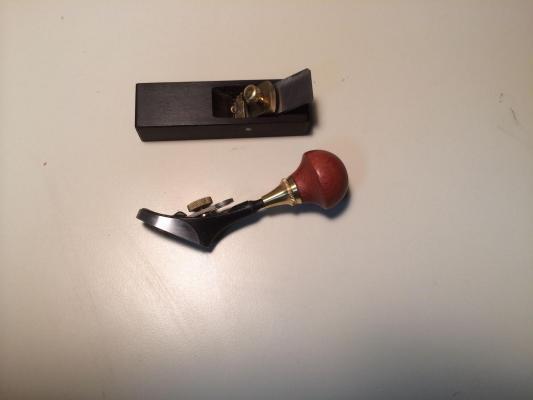
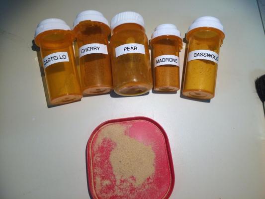
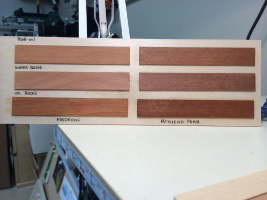
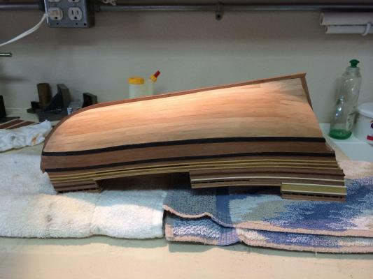
Paragon – a Modified Mayflower Part 8 – Hull Planking - 2 The planking above the upper wale was mostly completed, but I still had a few strakes left on the sides of the poop deck area. I wasn’t sure how I wanted to plank those, so I proceeded with the hull planking, which promised to be a major effort. I started by lining out the hull and identifying the position of the lower wale. This wale would be the border between the African Pear used for the upper hull planking, and the lighter color of Madrone for the planking from the lower wale down to the keel. I lined out the hull by following the process outlined in Chuck’s practicum on Lining Off the Hull for Planking, which can be found at the following link: http://modelshipworldforum.com/resources/Framing_and_Planking/Lining%20Off%20your%20hull%20for%20planking.pdf Once again I used 1/8” black artist’s tape for the lining. Once the line for the upper wale was established I used a light blue artists’ pencil to mark that line so that it stood out. I could no longer use the 1/8” planks that I had previously produced, so I needed to produce a supply of planks wide enough to allow spiling to extreme shapes, as shown in the following photo. I used plank lengths that would represent planks that were approximately 20 – 30 feet long in actual size – model size was 3” – 4.5”. My method of attaching the clamps was to apply a thin layer of PVA glue to the plank and to the hull with a small paintbrush, and to put 2 or 3 small drops of gap-filling CA glue at the ends and middle of the planks. I then held the plank in place for about 2 minutes so that the CA would hold. This took the place of using clamps. As soon as I started planking I had trouble with the planking at the bluff bow. I couldn’t get a clean line by using a regular compass, so I needed to develop a tool I could use for the spiling. I had on hand a basic carpenter’s compass, which had a small mechanism that held the pencil and allowed the pencil to be adjusted easily. I took the compass apart so that I could use the device for holding the pencil. I then milled a small piece of wood so that one side was grooved to hold a pencil, and so that there was a mounting slot and hole for the pencil holder. I epoxied a small brass strip to one side and a small brass rod to the other (at opposite ends). The small rod was very close to the pencil tip, and the brass strip was farther away, as in the following photos. With this tool I was able to properly spile the planks, even at the very tight bluff bow where the planks needed to be spiled to a very tight curve while also being tapered fairly radically. The end with the small rod was used for tight curves, and the end with the strip was used for gentle curves. This worked out quite well. I also want to mention some of the other tools I used for shaping planks. I have a couple of very small planes that work really well in shaping the planks. I also used several different rifflers and sanding sticks for shaping. I replaced the jaws of my Panavise with lengths of hardwood that would enable me to hold a plank over its entire length. When I had completed the hull planking down to the location of the lower wales, it was time to cut the wales. The wales were bent by soaking in very hot water, and then clamping them to the hull using rubber bands. The wales needed to be stained before they could be installed, since they would border finished planks along the top edge. I was so busy planking that I neglected to take photos of the process – once again I apologize. Here are some photos of the finished planking: There were some areas where I needed to use small amounts of filler. I had previously read on MSW about using sawdust for filler, so I made it a point to thoroughly clean my bandsaw before cutting out billets of planking wood, and then collecting the surface sawdust after sawing was completed. I mixed this sawdust with PVA glue to form a paste, and carefully pressed it into the slight openings where they existed. I made sure to wipe any overflow off with clean water. If you know the filler is there you can see it, but it gives a nicely finished appearance. The last item on the agenda was to determine how I would finish the planking, and the model in general. My choices were rub-on poly, oil-based poly, and water-based poly. My objective was to find a finish that would still leave a good contrast between the African Pear and the Madrone. I made up some test strips of both woods that would let me determine the best finish. The clear winner was the water-based poly. It also had the added advantage of being easiest to clean up. Next up will be stanchions, rails, etc. – fun work as compared to the stress and tedium of planking.


-
Thanks Patrick. Complex lines and curves made for a complex planking job, but a very good learning experience.
-
Hi Brian Our next meeting is in a couple of weeks, and I'm looking forward to seeing your latest work - fabulous! Frank
- 831 replies
-
- 1
-
-
- Armed Virginia Sloop
- Model Shipways
- (and 1 more)
-
Thanks Brian. I fixed the link (I changed the folder structure after I had copied/pasted the link into the post - duh!).