

Richard Braithwaite
-
Posts
128 -
Joined
-
Last visited
Content Type
Profiles
Forums
Gallery
Events
Posts posted by Richard Braithwaite
-
-
1 hour ago, Ian_Grant said:
Richard, this is groundbreaking modelling! Poor guy hits the back of his head with every stroke...No wonder they had towels wrapped around the beams in Olympias.
I assume by "Mark II design" you refer to another actual ship, and not another model from you? 😀
I suppose its a good thing that his head is made of wood...
Its taking me long enough to build this one so I don't think Ill be making another one soon. I have been developing a computer simulation, however, which I'm hoping might be useful in supporting some design work to assess the extent to which performance could be improved by optimizing the layout.
- mtaylor, Ian_Grant, Keith Black and 1 other
-
 4
4
-
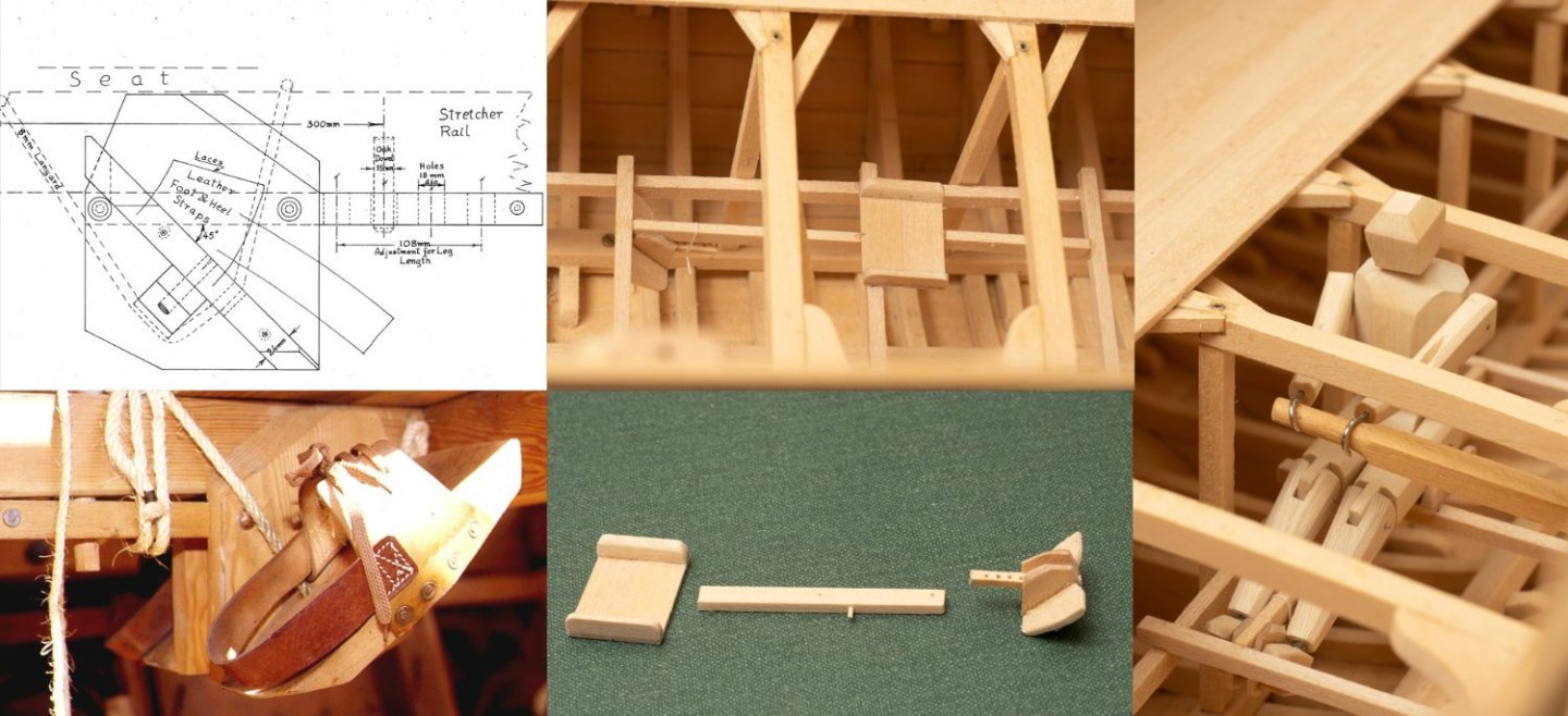
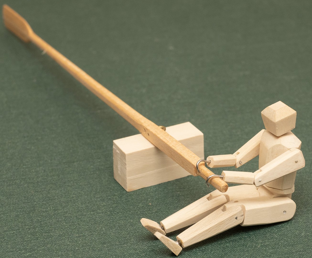
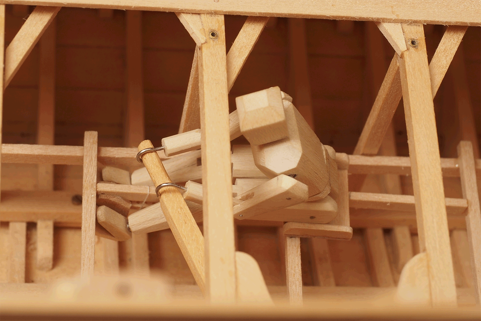
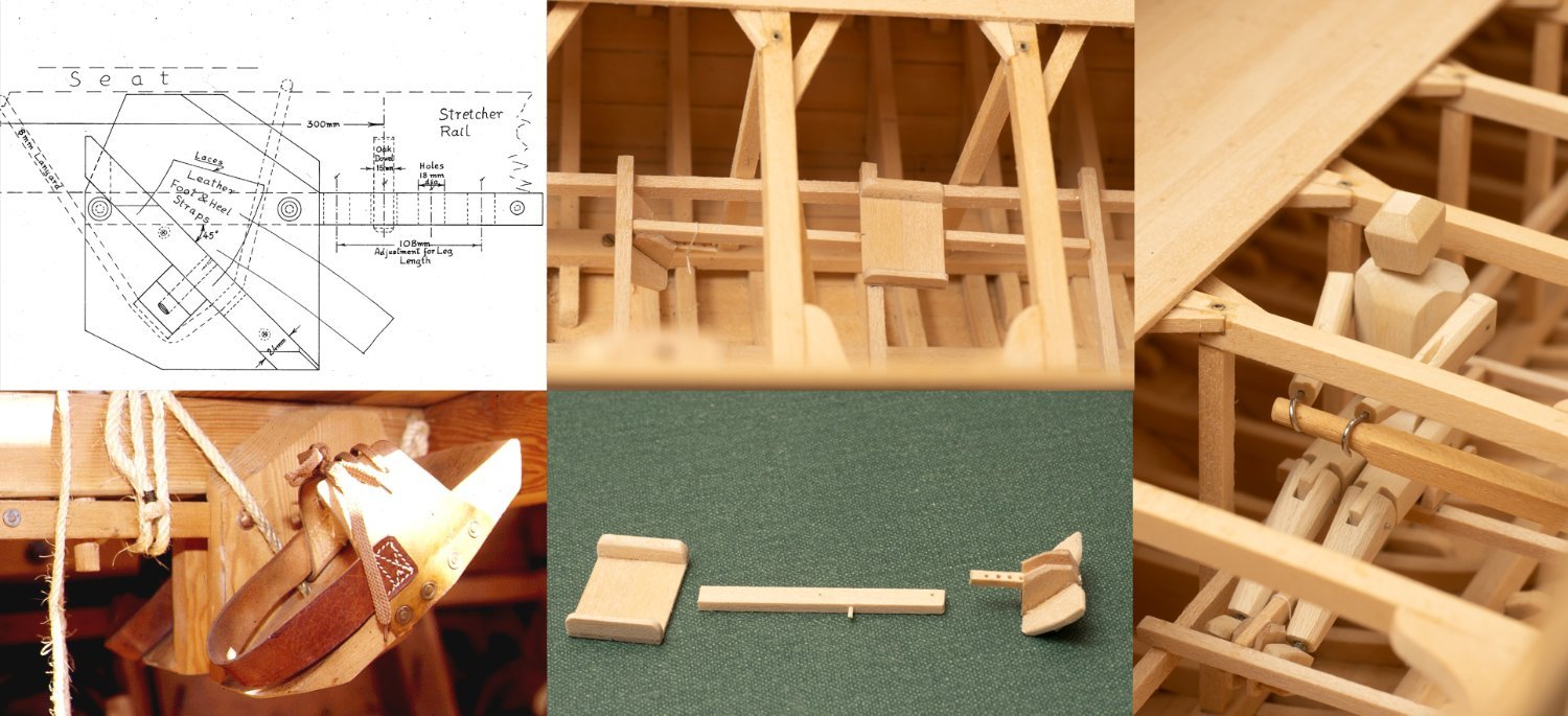
A little animated gif of my the manikin at this thalmian position. His rowing technique leaves something to be desired (!) but he does illustrate one of the difficulties of the design. The limited space between the deck beams meant that these rowers tended to his their heads at each end of the stroke. It was a particular problem at the finish and could be dangerous if anyone caught a crab… They mitigated it on trials by putting the smallest rowers in these positions (I based my Manikin on a 50% 600BC Athenian build…) and fitting a restraining rope to the oar so that it wouldn’t break their necks if they caught a crab. Not ideal, and the power delivered from this level suffered accordingly. One of the issues to address in any Mk II design…

Just noticed that his foot rest had dropped and disengaged from the locating dowel. Should have lashed it tighter... oops!...
I think my manikin achieves about 720mm of the full 800mm design stroke. I have modified his joint already to make him a little more flexible but he still had problems pulling the oar right into his torso at the finish of the stroke (as you can see from the GIF above). However, I don't think they often achieved the full 800 mm stroke on trials for the reasons given above...
-
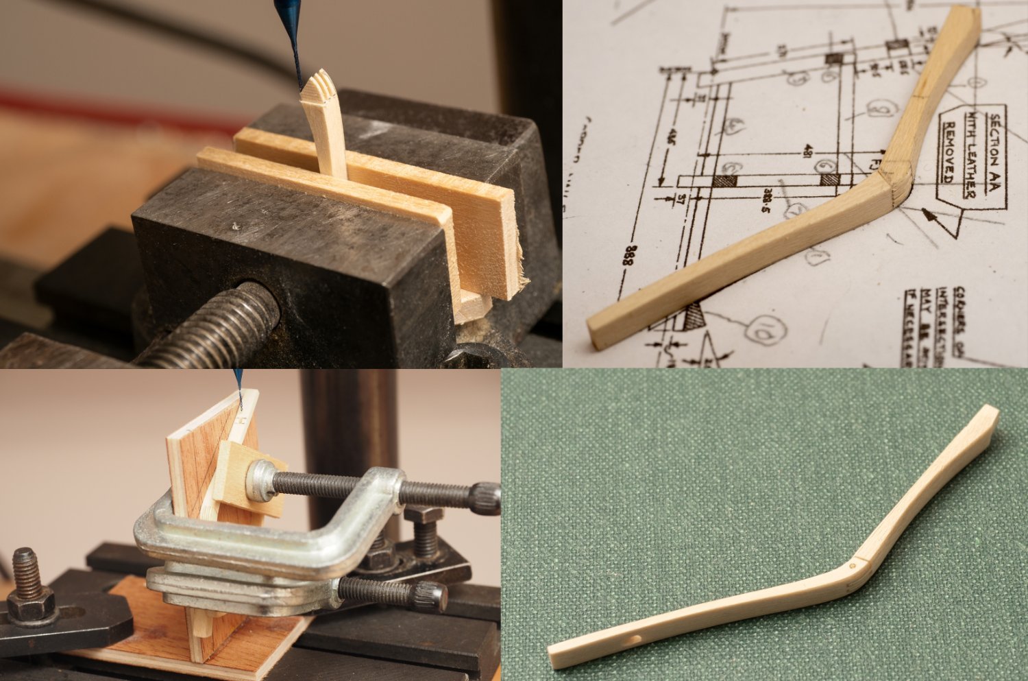
First Thalmian (lowest level of three) Rowing position in place (minus the leather foot and heel straps. The small dowel in the stretcher is used to locate the footrest and allow some adjustment for the rowers leg length. These foot rests are pretty much hidden underneath the seats once they are all installed.
(Drawing shown is an extract from John Coats Plan No 9 titled "Trieres Foot Stretcher" © Estate of John F. Coates, reproduced with permission)
- Keith Black, Ian_Grant, GrandpaPhil and 2 others
-
5
-
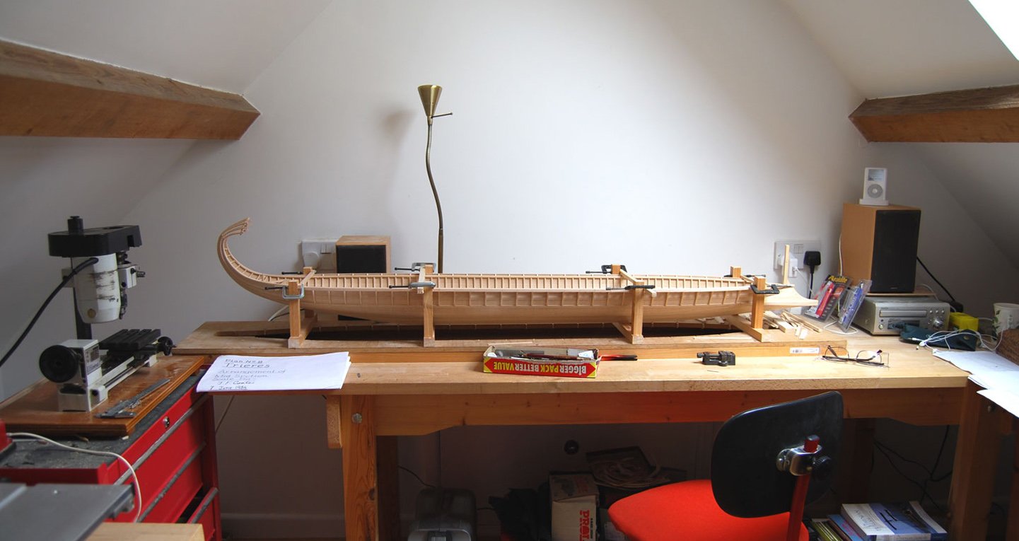
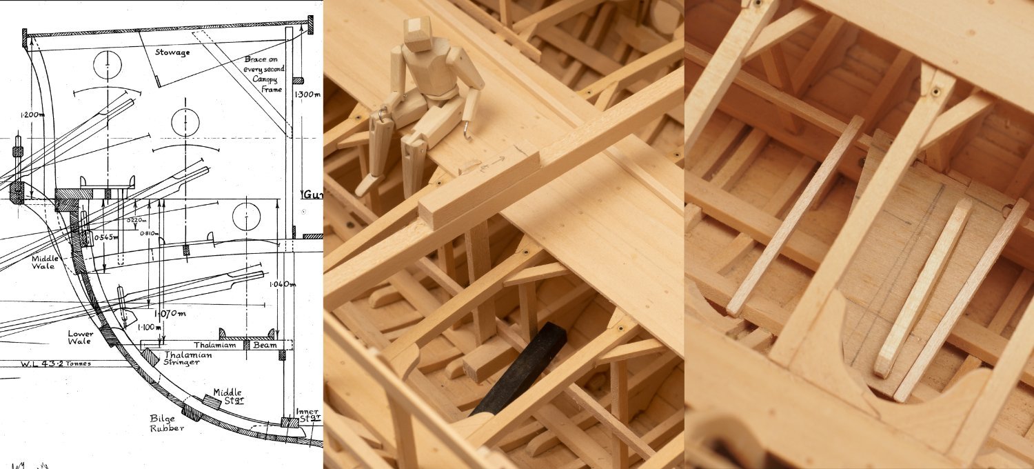
Removed the canopy sections so I can start to install the oar seats etc for the lower level (Thalmian). Probably should have done this earlier in the build, but the ability to dismantle my model helps me get away with it!
First photo shows the longitudinal stringer that supports the inner end of the Thalmian beams installation using a jig to ensue the correct vertical location. The next photo shows a couple of Thalmian beams in place with a plywood jig to fix the 3 degree rake. The deck beams, walkway, inner stringer etc. all comes away as a boltable assembly, which means I can only fix the inner ends of these beams. The outer end is left resting on the Thalmian stringer. I'm hoping that once I have installed the seats and stringers (which connect the beams longitudinally) this cantilevered arrangement should be stable enough...(Extract of John Coates Midship Section Drawing ‘© Estate of John F. Coates, reproduced with permission.)

- chris watton, BANYAN, mtaylor and 4 others
-
7
-
1 hour ago, mtaylor said:
The manikin is a brilliant idea. Many of use "fixed" figures for scale but have one articulate for rowing is a better plan.
Looks a little "robotic" though. Hopefully can use them for illustrating how the three tiers work together through the rowing stroke.
I don't think I will be making 170 of them though...
-
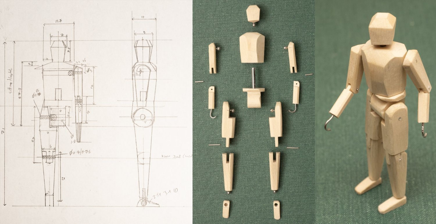
An Athenian Marine...
I've been looking for a scale wooden artists manikin to demonstrate ergonomics of rowing equipment geometry etc. but they are all on much too large a scale for my model. So I decided to have a go myself at a 1:24 version.
For the dimensions I found a good source of ergonomic data for US Marines (https://apps.dtic.mil/sti/pdfs/ADA581918.pdf). I took the data for the 50th percentile marine and scaled it according to the mean height of a classical Greek male (approx. 5 ' 7" as identified from Archaeological studies of skeletal remains ref S. C. Bisel, J. L. Angel, "Health and Nutrition in Mycenean Greece: A Study in Human Skeletal Remains," in N. Wilkie, W.D.E. Coulson (eds.) Contributions to Aegean Archaeology: Studies in honor of William A. MacDonald (Minneapolis 1985)).
Given both US Marines and Athenian oarsmen are likely to be of a similar muscular build, I thought this approach would give a reasonable approximation. I know that trials on the full size of Olympias had some difficulties fitting 20th century oarsmen in some of the rowing positions...
Anyway the resulting model is shown below:
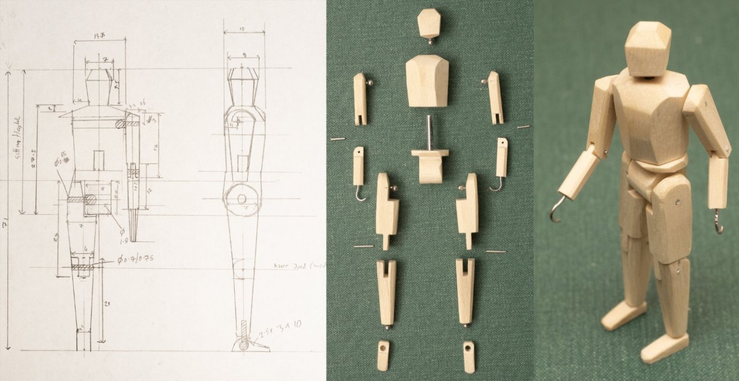
I've used two sort of joints to give the required mobility:
1. ball ended pins to simulate the ball and socket joints of the shoulder and hip (and the rotational joints of the neck and heels)
2. simple one degree of freedom pin joints for the knees and elbows.
This works for an oarsman at around midstroke as shown below:
And finally standing on the helmsman's platform of the model to give an indication of scale:
I'm planning to make 3 of these manikins so I can check the arrangement of the rowing equipment (seats, stretchers etc,) on the model for each triad of oarsmen.
-
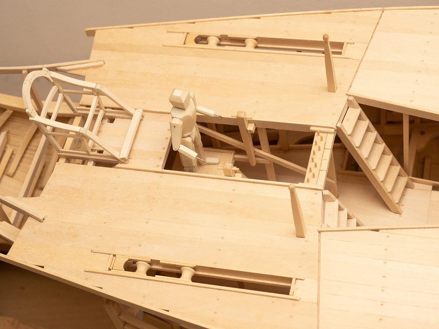
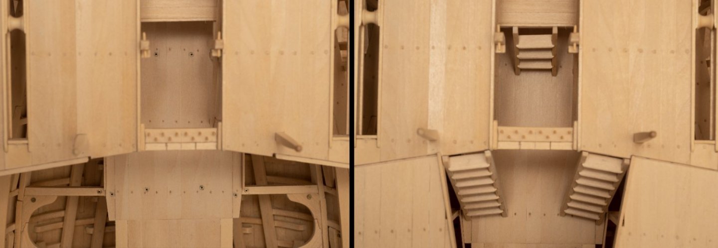
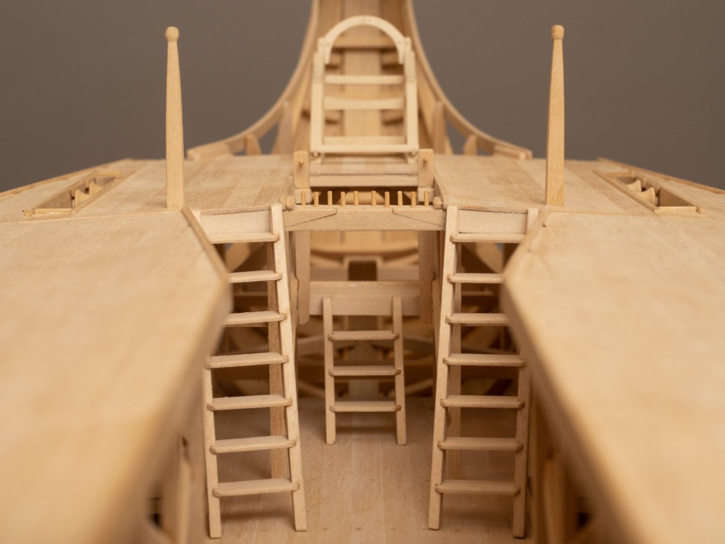
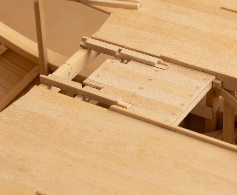
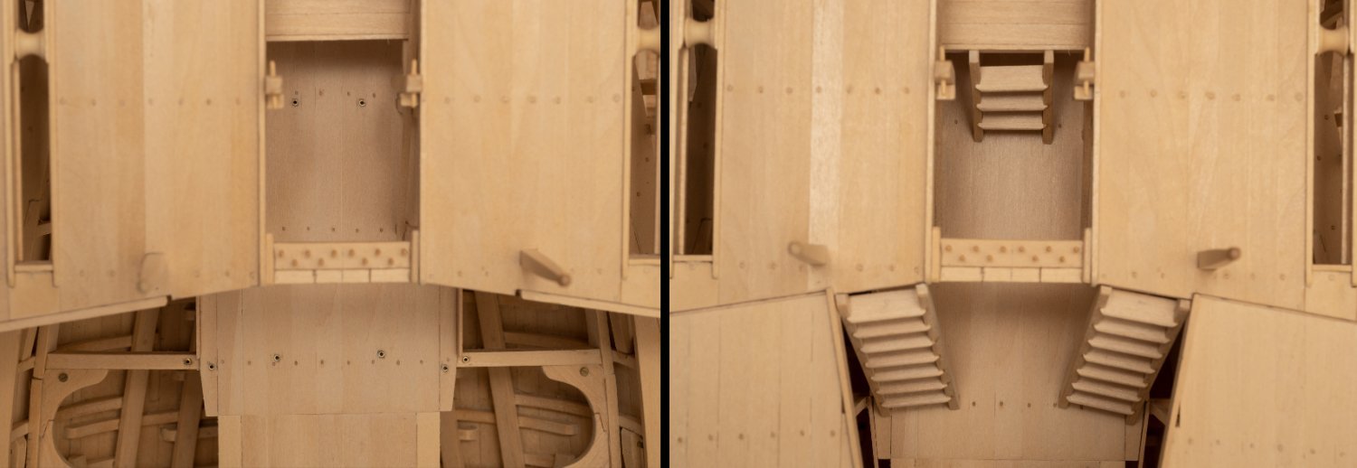
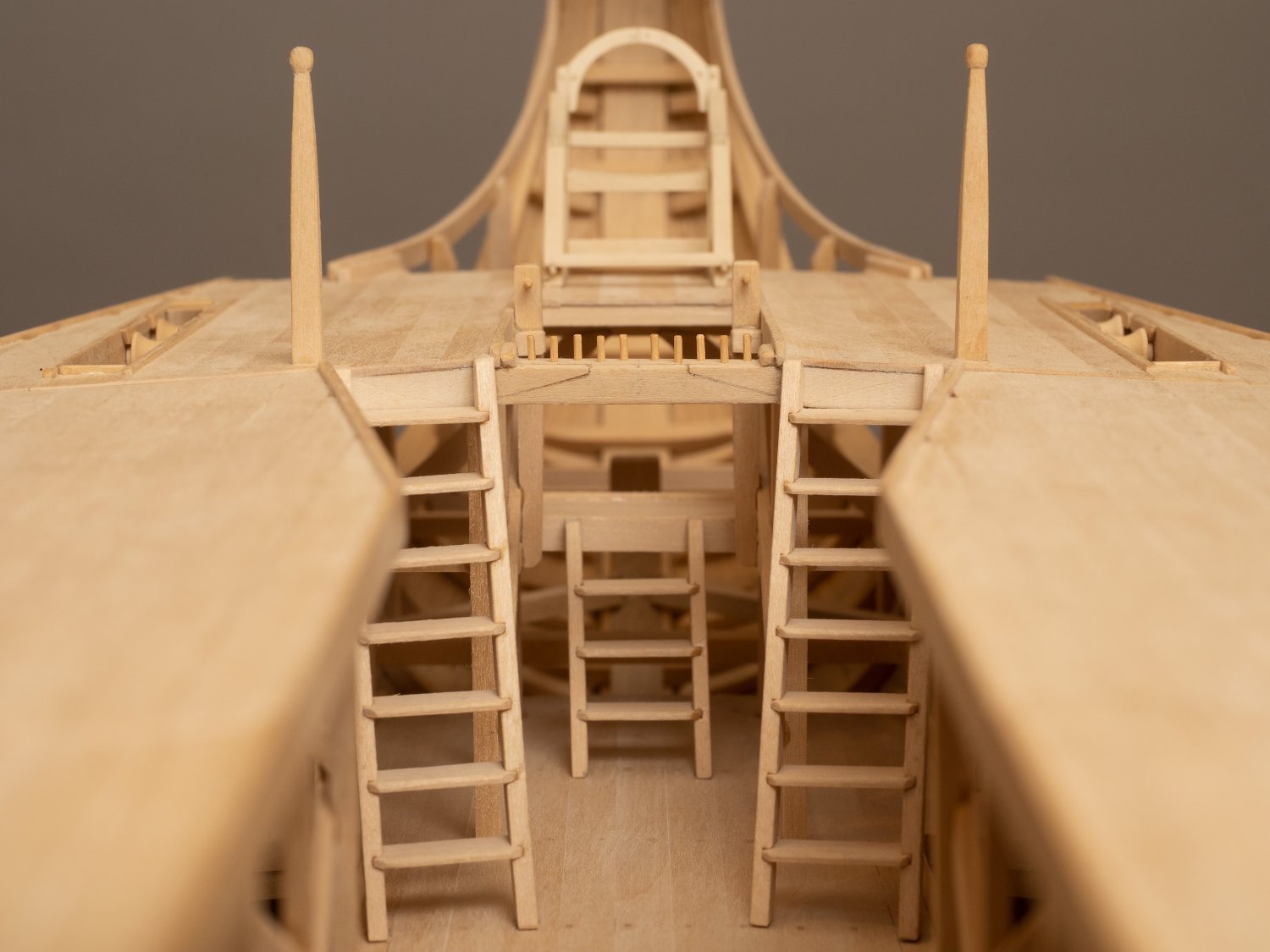
Insallation of the ladders on the model.
The left hand image shows the aft end of the gangway and part of the helmsman's platform with the aft canopy sections removed. the brass lined holes in the deck are to locate the pins on the base of the ladders. The brass lined hole for locating the aftermost stanchion of the aftermost canopy sections can also be seen in the deck beams just outboard of the gangway as can the bolted lodging knees that are part of the system that enables the unbolting and removal of the entire deck assembly.
The right hand image shows the ladders (and the aft canopy sections) installed.
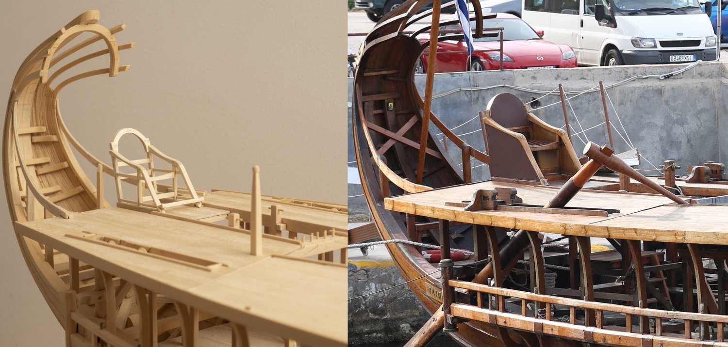
Finally a view of the ladders, quarterdeck (with Trierarch's chair!) and helmsman's platform looking aft from canopy level. The slots in the quarterdeck (with the turned rollers) are form the steering oars to pass through which are fitted with athwartships tillers controlled by the helmsman standing on the platform in front of the Trierarch.
-
-
-
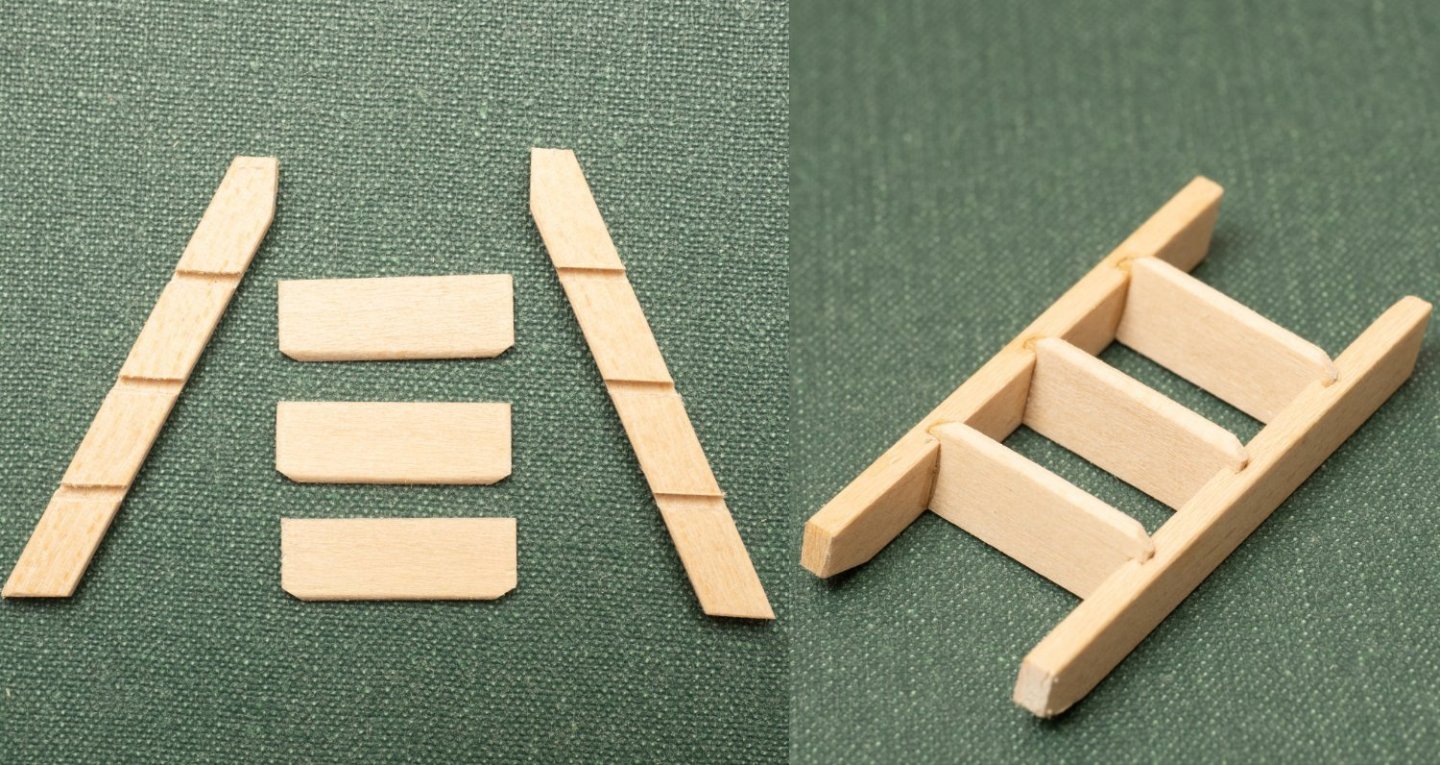
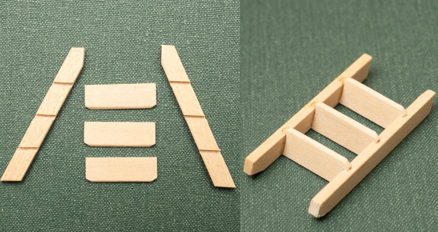
works quite quickly. Here is the assembled ladder to the helmsman's position:
- chris watton, GrandpaPhil, BANYAN and 4 others
-
7
-
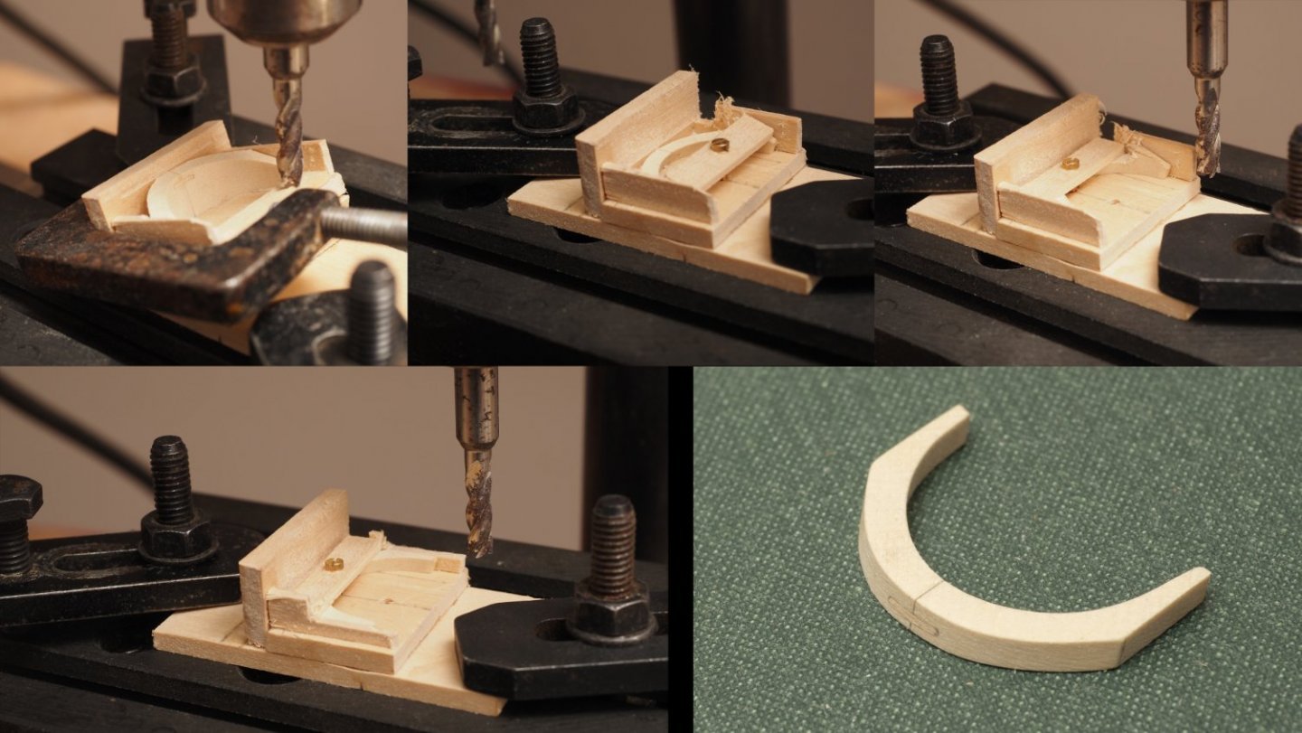
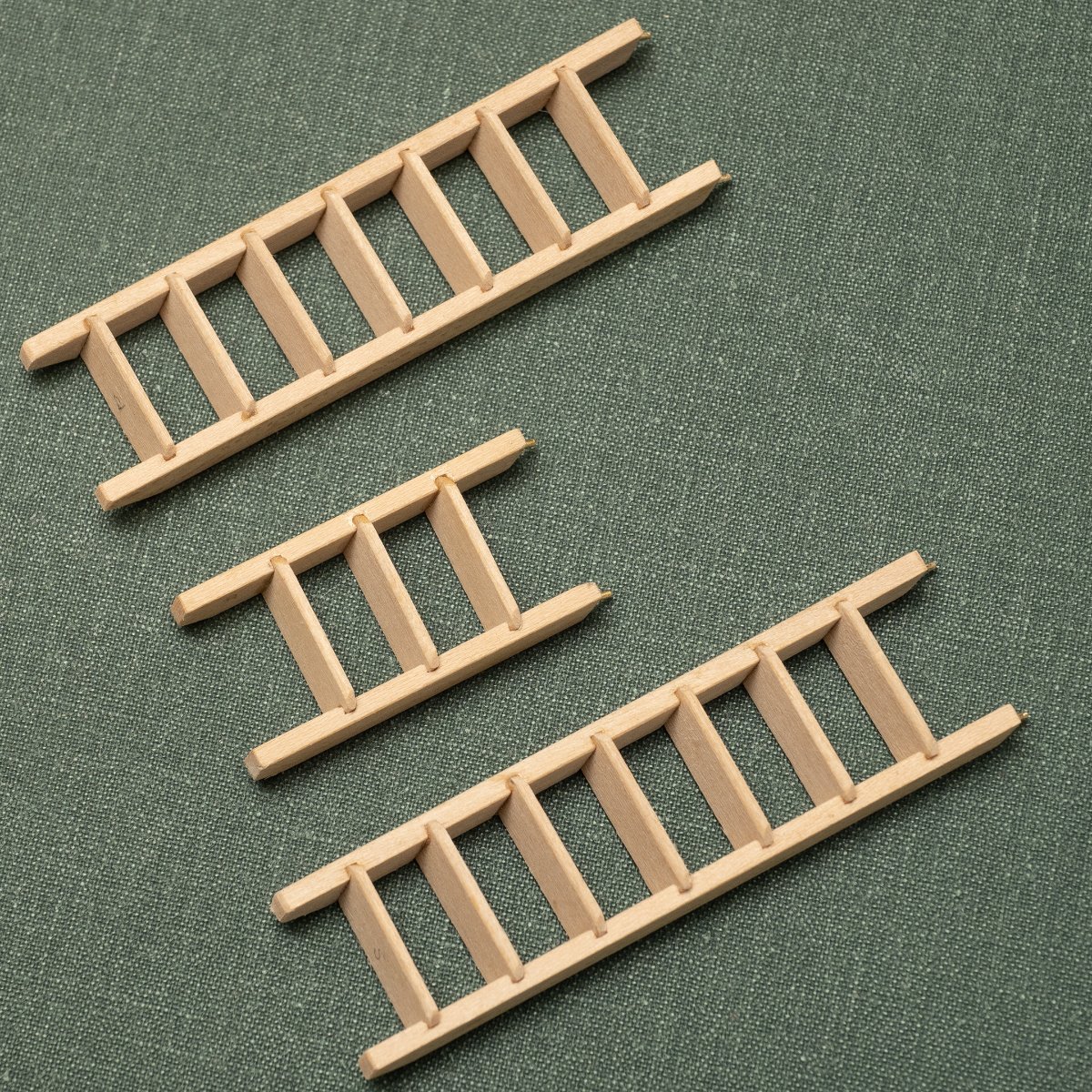
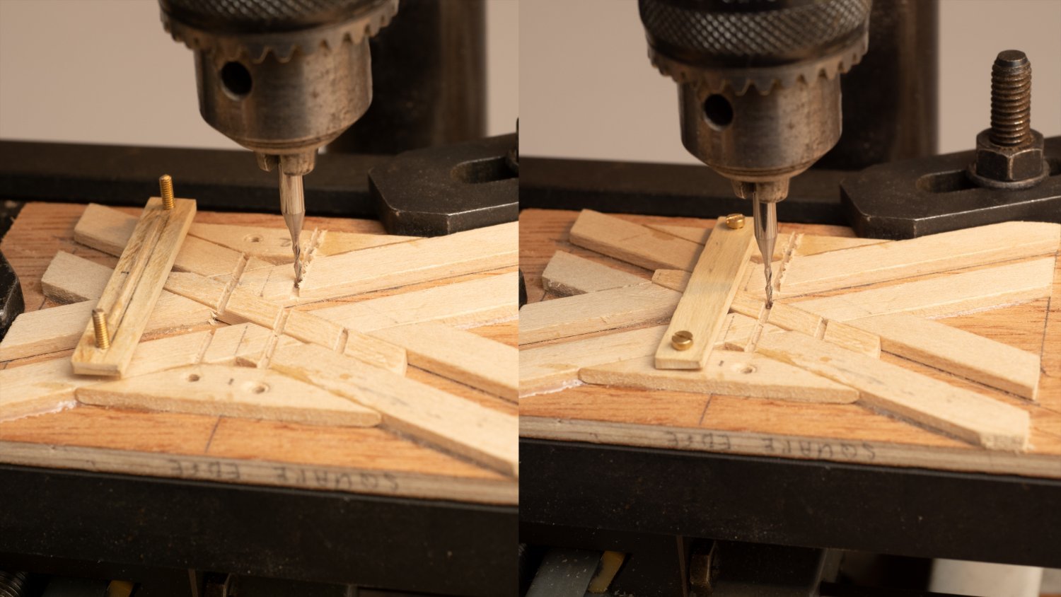
I've got 4 ladders to build and have constructed this jig for cutting mortices for the rungs.
.
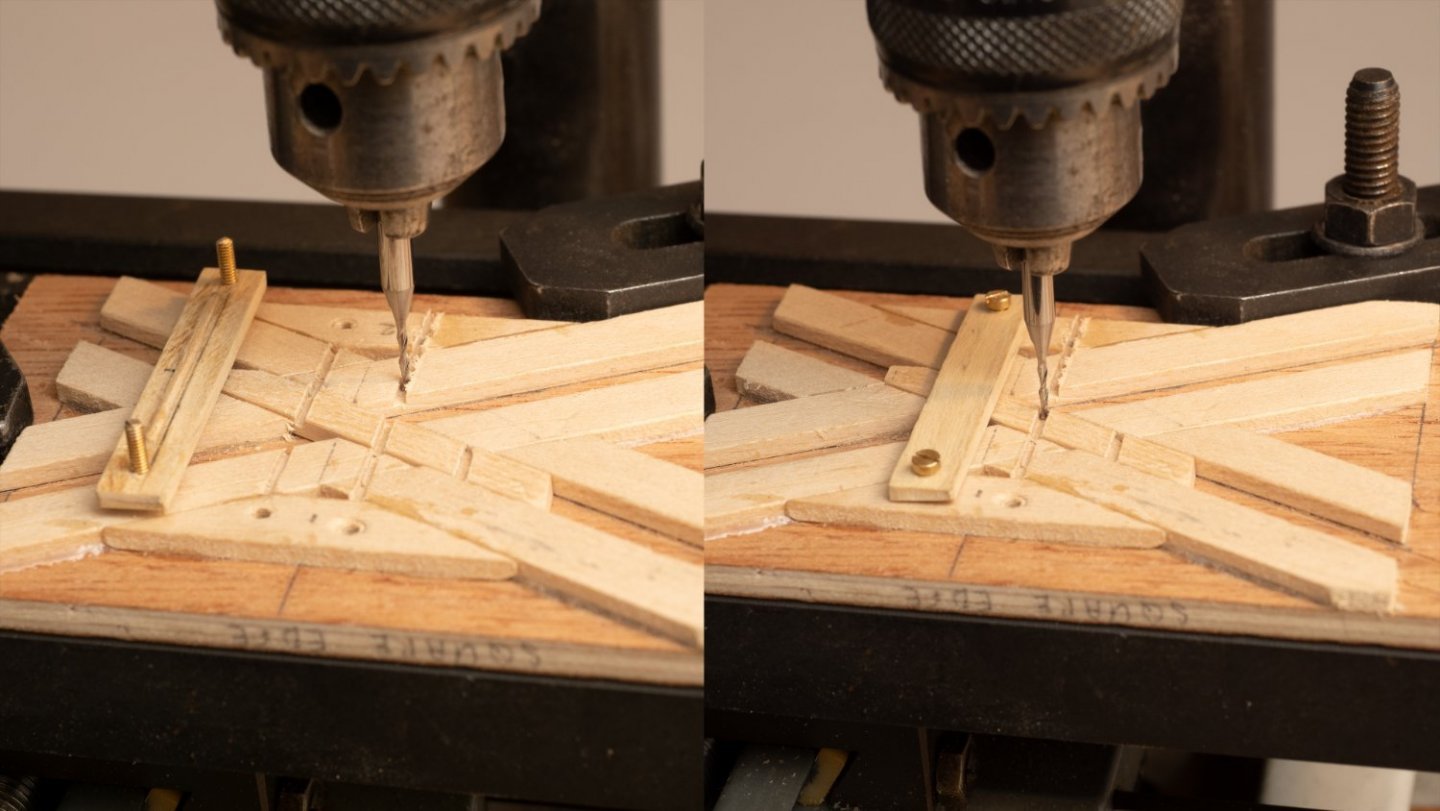
- B-Ram, Ian_Grant and GrandpaPhil
-
3
-
On 2/23/2022 at 10:10 PM, Johnny.D said:
Now the main structure of the ship is nearing completion, will the next stage see the start of the masts and rigging, because I am highly intrigued how this will be brought to life matching the mind blowing quality of the ship so far.
Will get round to the rigging in the end... Don't think I will make sails though. My main interest is in the oar system...
-
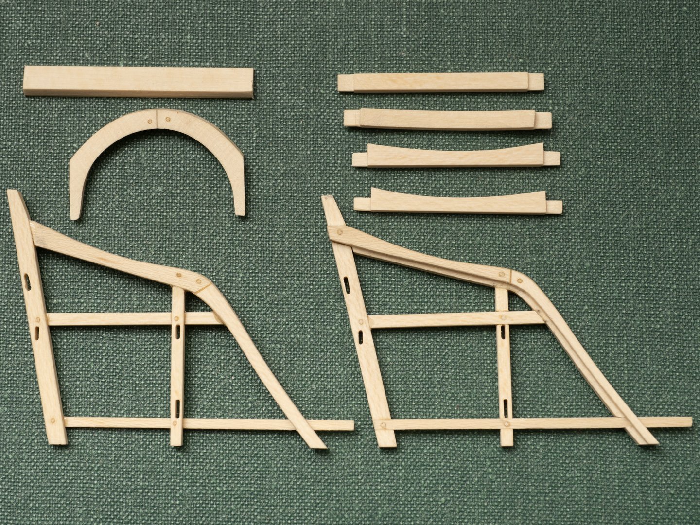
A view of the seat frame located on the quarterdeck compared with a picture of the full size Olympias. I have built my model as closely as possible to Coates design drawings (the drawings sheets contradict one another in some cases - as you would expect from what was essentially a prototype for a reconstruction of a warship which hasn't been built in living memory...). These include:
1.Differences in framing of the stern.
2. Removal of the footrest from the Trierarch's chair.
3. Differences in the leather upholstering of the Trierarch's chair.
4. Removal of the handhold post at the head of the ladders from the quarterdeck to the gangway.
5. Additional bracketry alongside the steering oar slots.
I am sure some of these changes were incorporated at build and others were introduced as sea trials progressed. Not unlike my own experience of designing and building modern ships!

-
Seating for the seat (?) installed on the quarterdeck. I've taken a piece out the planking between the morticed longitudinals to allow the seat to be lashed down the to the deck as shown in the trireme seat drawing. This differs from the drawing of the quarterdeck (extract shown below with the photo of my model) which would not have allowed for the seat to be lashed down in this way.
- Ian_Grant, mtaylor, GrandpaPhil and 2 others
-
5
-
-
-
On 10/30/2021 at 4:06 AM, Ian_Grant said:
Hi Richard! I'm glad you found this, and may I say I'm a great admirer of your gorgeous triere! Of course I had seen your smooth mechanism before but I wanted to try something different.
By the way, I wonder why I get no notifications if someone comments in this log that I started?
Update: I've been testing code, overcoming newbie arduino problems and getting used to it. At one point I was stuck for hours trying to get a bunch of nested IF's to do what I wanted! 🤪 I finally got around it by rewriting code to avoid such deep nesting. I just completed writing the program last night but only the first third is tested. As now written, the oar motion will simply be rectangular because I wanted to try to get the jig's oars going to be able to test the turning features etc. I can easily refine the stroke shape later. I wrote the code to stop the inside oars in a middling turn, and reverse them on a hard turn, whether going forward or backward. Should be interesting. Also, as written, as throttle advances there is an initial range over which the strike rate (oar cycles per minute) is constant but the sweep length gradually increases to full, then a new range over which sweep length stays at full but strike rate increases, to max speed (which would be short duration for actual human rowers). It also occurred to me while walking the dog this morning that there's no reason for the oars to move at the same speed on the power and return strokes; I will try speeding them up a bit on the return stroke to see how it looks.
Software provides flexibility, but it also means there are a thousand possible ways to do this. I'd need an actual model to finalize the parameters eg how effective is the rudder for slight course corrections without changing the oar motion, when exactly to reverse oars on a turn, what's a good strike rate for the slower speeds, what's a reasonable strike rate at full speed, etc.
Rainy weekend coming up so I will try debugging. Another video to come soon I hope.
Really interested to see how this turns out. My rowing machine is fairly primative in that it describes a constant speed elliptical orbit and will not follow how an actual oarstroke would work when operated by a real human being (particularly during the acceleration phase from a stationary start...) I have been doing some research into this and writing some simulation code (in C++ for speed of execution). the purpose of this exercise is not to support any rowing machine but to gain an greater understanding of oared warships and how they could have been optimized in design.
Some time ago I found a paper online describing a rowing machine model that used a weighted pully system so that the pressure applied during the power stroke (when the oar blade is in the water) is constant from catch to finish (cant find the reference now...) which I thought might be quite interesting..
-
On 2/13/2022 at 1:12 PM, KeithAug said:
Eberhard
I see a lot of Meccano at our local auction house. It generally goes for a song as kids these days don't seem to have any enthusiasm for nuts and bolts. I think lego put an end to the Meccano era. I used to have a number 9 set (the second largest) but many years ago my father took it away to play with it. He has been dead for 10 years and I'm not sure what happened to it However I like the idea of making a serving machine from Meccano. You might be able to source more bits for you Marklin set at your local auction.
I have a load of Meccano that I inherited from a cousin years ago. Made various things with the kids over the years but hadn't thought of using it for rope making machines etc.
- KeithAug, Keith Black, mbp521 and 2 others
-
5
-
On 2/12/2022 at 11:52 PM, BANYAN said:
That is some superb and incredible small-scale joinery Richard.
cheers
Pat
Probably an excessive investment in time given what a minor component this chair is of the overall model....But I've found it an interesting challenge to see what I can achieve with a hard, fine grained wood and a Unimat lathe/milling machine..
This project has been going on for so long now that I tend to see it as a series of sub projects and get my satisfaction from each of them rather than targeting overall completion...
Hopefully, Ill get there one day, but then Ill have to find a rather large area of the house to keep the model!!
-
-
-
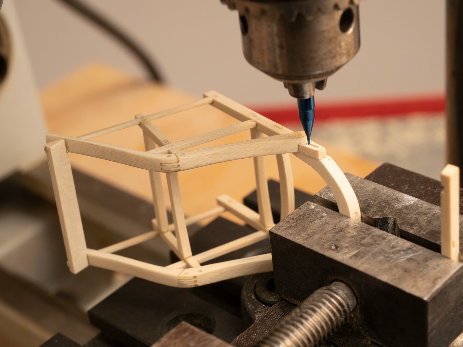
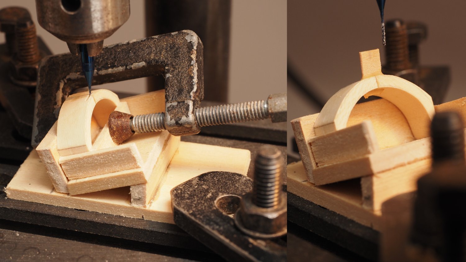
Continuing with the Trierach's seat back.
Photos in order from top left:
1. Seat back reoriented in jig. Shown after the rear face has been machined.
2. Jig altered to take out the 20 degree angle so that the front face can be machined parallel to the rear face. In order to hold the piece down I designed the jig with two clamping positions. This photograph shows the first clamping position which allowed the top half of the front face to be machined.
3. Clamp moved tot he second position so that the bottom part of the front face could be machined.
4. Front face completely machined
5. Completed seat back.
As the maximum dimension of this part is only 23mm I think I would have struggled to make it without the help of my Unimat🙂
- GrandpaPhil, Ian_Grant, Brinkman and 6 others
-
9
-
-
Richard,
I've also spent many years developing hullforms as a Naval Architect in England. Rhino is a great product, which I find really intuitive and easy to use. My main application was developing early stage concept design of warships and then rendered them using the addin renderer flamingo. My workflow generally involved developing the hullform in Paramarine and then importing the iges surface into Rhino to develop the superstructure and detailed 3D model for visualization. Main reason for doing it that way was because we needed the Paramarine model for sizing and analyzing the design before we reached the stage that we wanted a more detailed 3D model. Paramarine is slightly painful for use for generating hulls (although you can get proficient in just about anything if you really have to!!!). Rhino is also a lot less expensive to buy.
Looking forward to seeing how you go about hull modelling in Rhino
BTW Have you ever tried the Rhino addin ORCA?
- Egilman, mtaylor, scrubbyj427 and 1 other
-
4


One more small cog c. 1410 by Brinkman - scale 1:13
in - Subjects built Up to and including 1500 AD
Posted
I like your method of taking the shape of the floors. I built my trireme model is a similar way (planks over a jig and then shaping frames to fit...) It took ages, as every frame was different...
And after