

Richard Braithwaite
-
Posts
128 -
Joined
-
Last visited
Content Type
Profiles
Forums
Gallery
Events
Posts posted by Richard Braithwaite
-
-
-
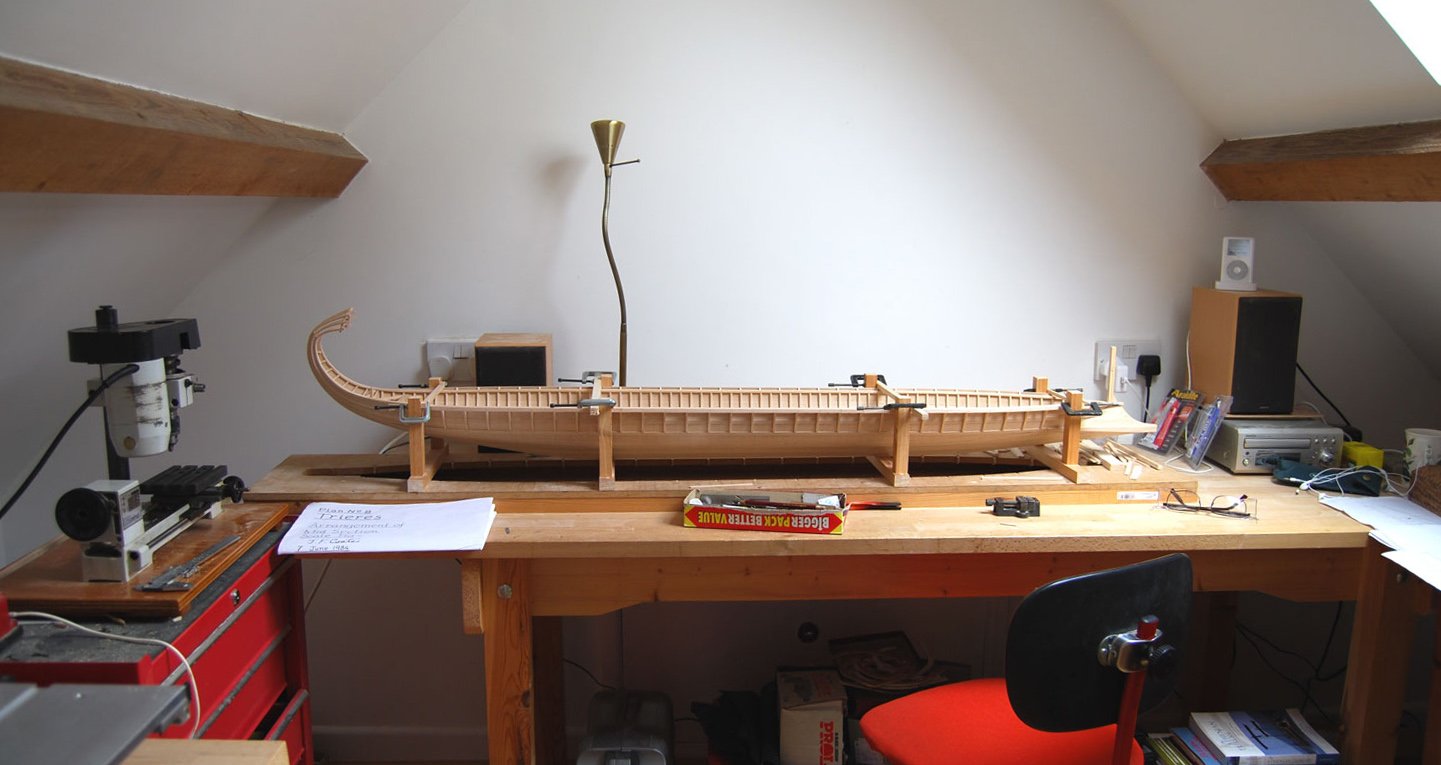
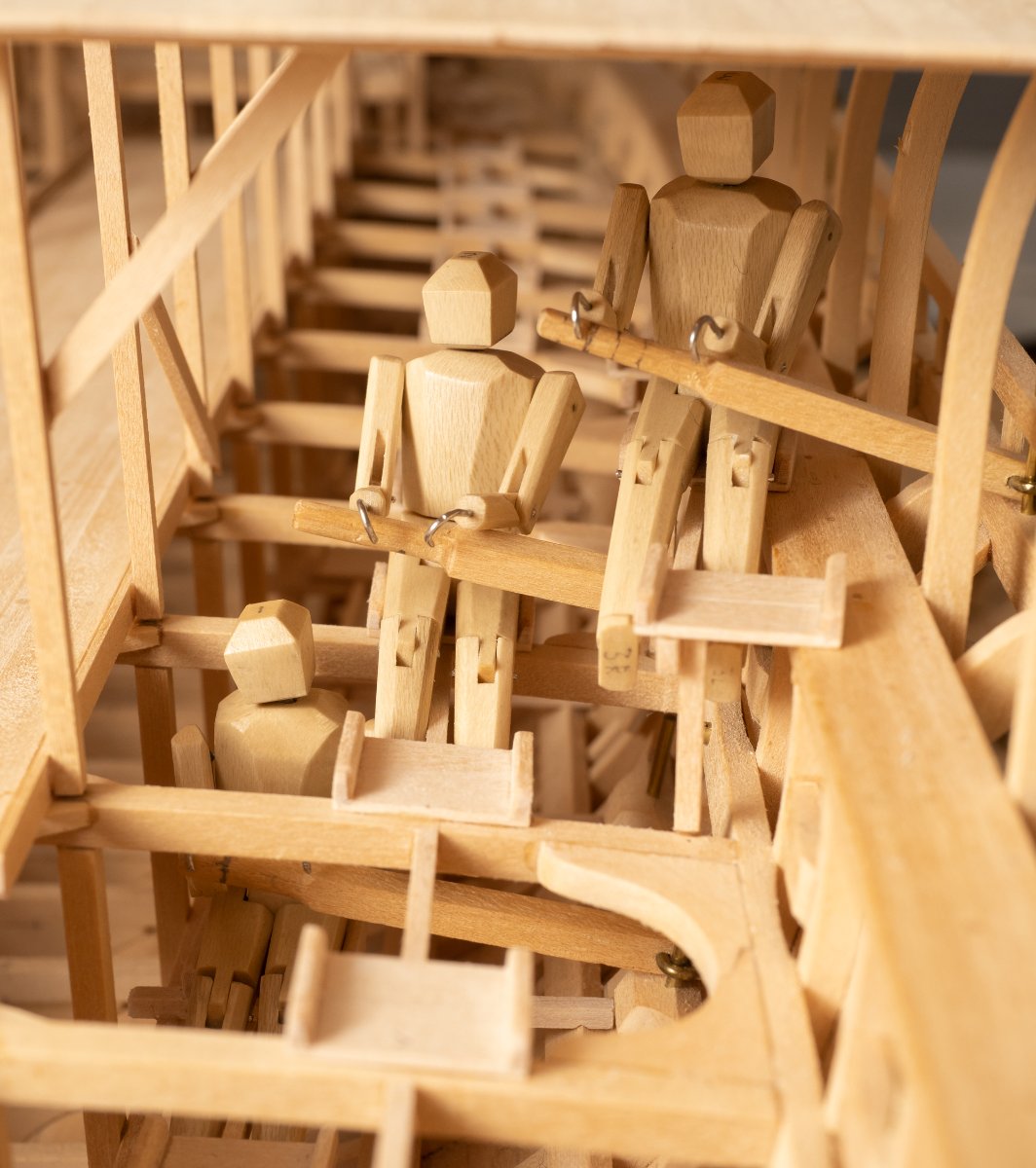
First check on the ergonomics with my trusty triad of marines:

Still to fit their footrests...
- Louie da fly, GrandpaPhil, Siggi52 and 10 others
-
 8
8
-
 1
1
-
 4
4
-
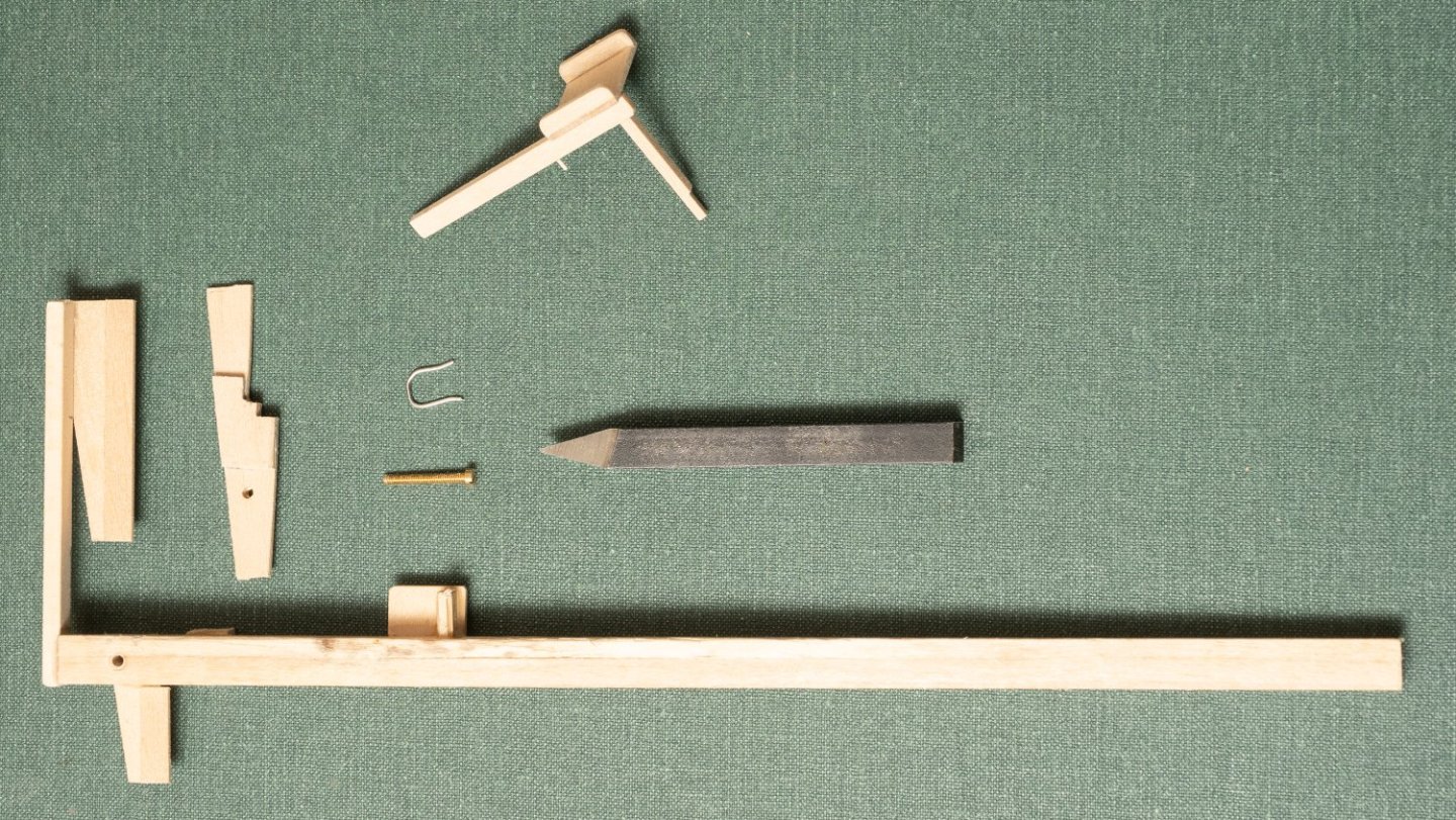
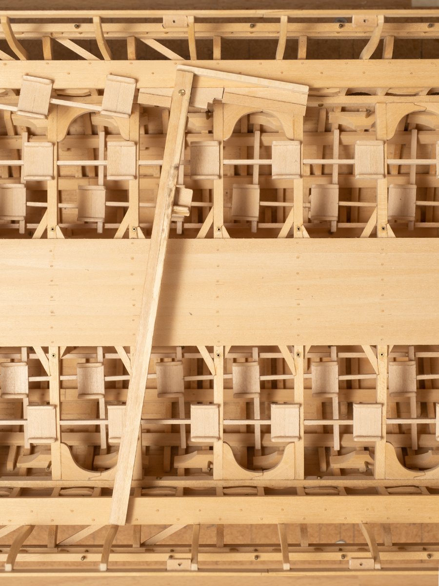
For some reason its taken me a long time to work out how to install and jig the upper seats...
The jig ive ended up with at this stage is shown below together with a seat assembly (seat+ foot stretcher + support pillar).
The jig consists of two parts. The main part is intended to hold the seat level athwartships and at the 9 degrees rake to the centerline with a removable section that can be unbolted so that the jig can be removed after fixing the seat in place.
Here is the jig in place in the model:
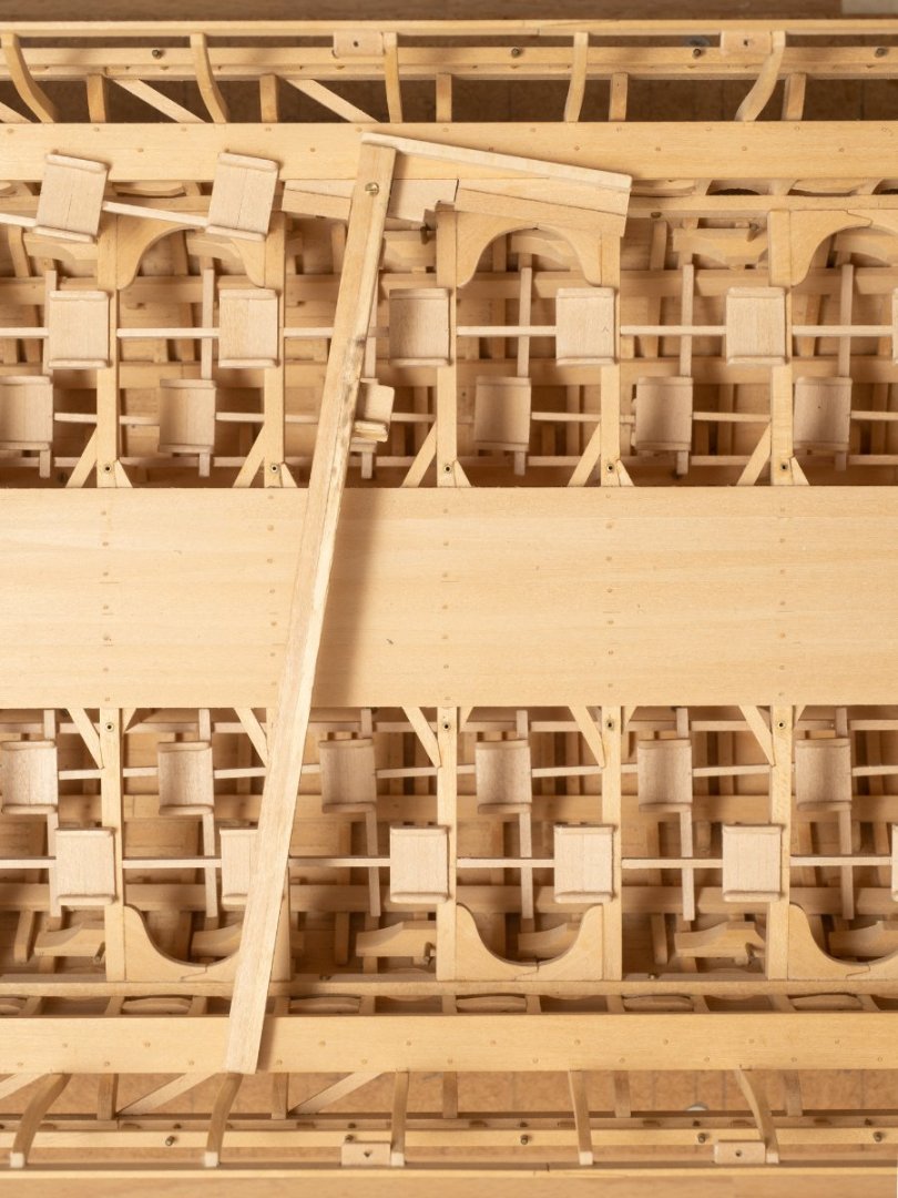
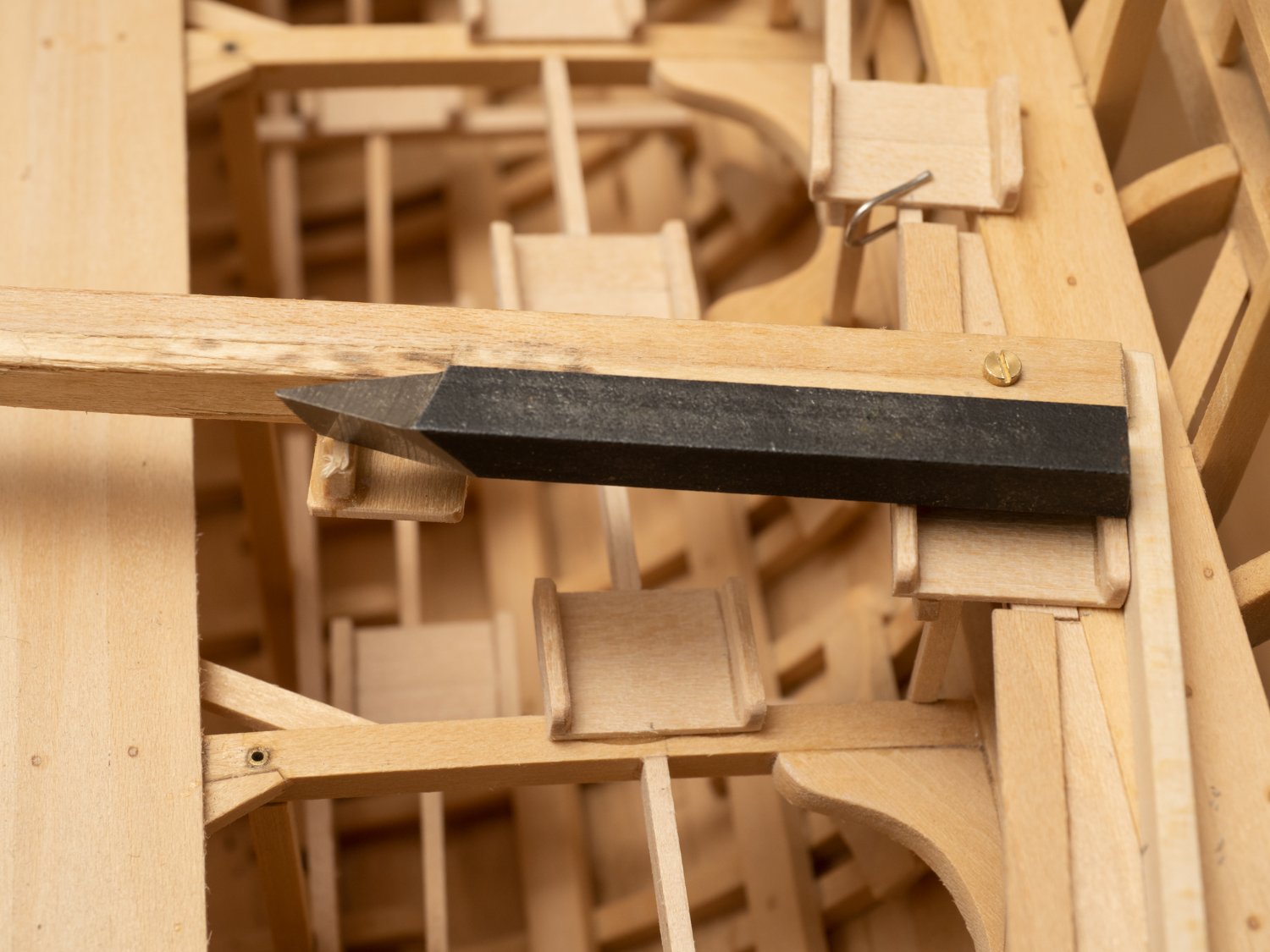
And, finally with the seat assembly in place:

The seat is assembly is fixed to the seat forward of it by its foot stretcher (held in place by the steel clip while the glue dries) and to the beam underneath by its support pillar. The intention is that all the seats form part of the removable part of the model and so this seat assembly can not be glued to the sheer capping...
The lathe cutting tool is functioning as a weight to hold the seat down in the jig while the glue dries...
-
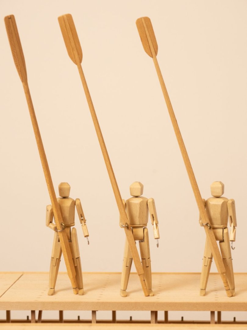
My triad of oarsmen completed.
From right to left: Thalmian, Zygian and Thranite oarsmen holding their appropriate oars.
The oars shown are based on the original oars for Olympias which were used for most of the sea trials. The blades are designed with a different shape to account for the differing vertical angle of immersion for the three different levels.
A lighter version of the oar was later trialed (where all three levels used the same design).
-
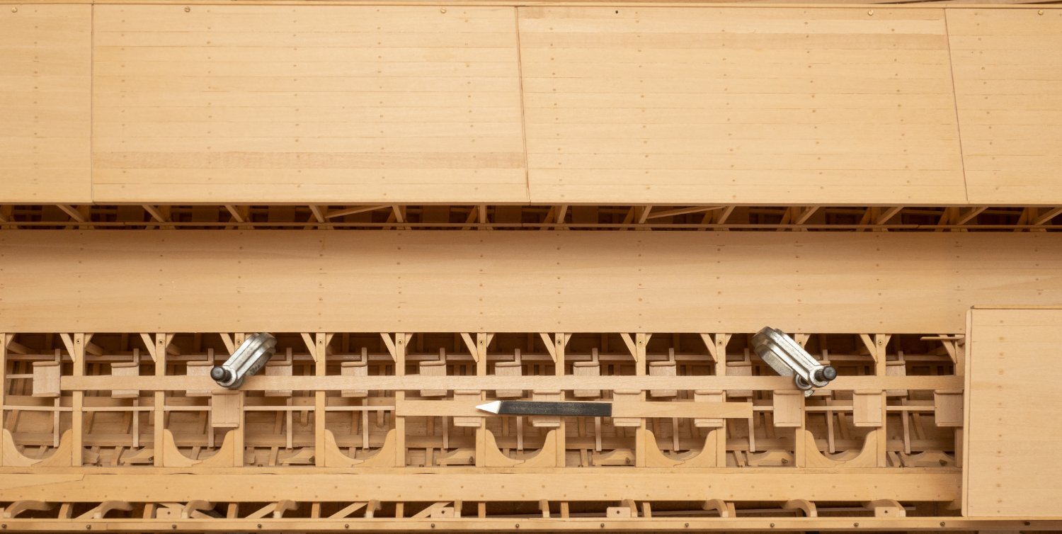
Completed port side Zygian seats:
- Archi, Keith Black, Prowler901 and 11 others
-
12
-
2
-
-
21 hours ago, Louie da fly said:
Agreed. I wasn't able to do this on my dromon as the scale was too small (1:50), but I would have loved to. Kudos for taking it to this level to get the proportions and angles correct.
Steven
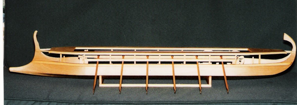
Yes, I am finding that 1:24 is about as small a scale as I can manage. The main reason for the full scale reconstruction was to demonstrate that it was possible to arrange 170 oarsmen, each with their own oar, in a ship 37m long... So I wanted to be able to show that this could work on the model...
The clearances between the oar blades, and hence the geometric tolerances for building many critical areas of the ship, are necessarily very tight to achieve this even at full scale let alone on a model...
- Keith Black, Ian_Grant, KentM and 2 others
-
5
-
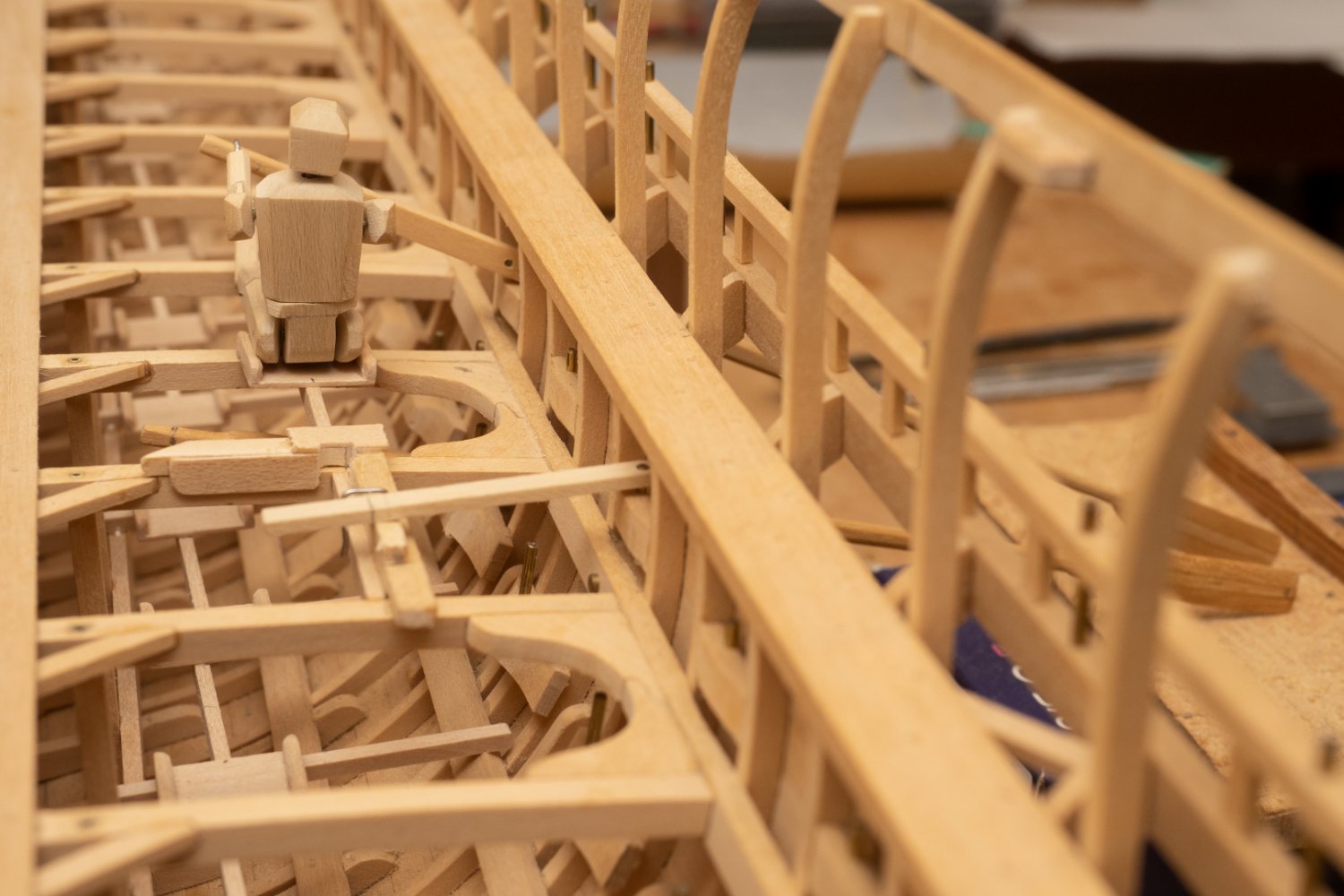
Starting the installation of the second tier (Zygian) of oarsmen seats. Again, my Manikin is helping to confirm that the seat is in the right place for the downward angle and sweep of the oar and that there is no interference with the lower (Thalmian) oarsmen. The oar blades ae resting on a block of wood placed to give the right downward angle for complete immersion of the blade in the middle of the power stroke (at the design displacement). One the inboard distance of the seat is established I constructed the jig for installing the oarsmen stretchers at the same distance from the tholes which can be seen in the next bay forward of the manikins position. Part of this jig holds the new stretcher in place, perpendicular to the deck beams and the other part is a simple "ruler" that fits over the thole pin marked for the correct distance inboard. I will need to remark this for the shorter oars at the ends of the vessel...

-
On 10/3/2022 at 11:36 PM, Ian_Grant said:
Richard, is the plan still to install an oar drive mechanism? If so I look forward to it eagerly.
Yes that is still the plan. However, at the moment I am concentrating on completing the model with as little concession to that as possible. I want the mechanism to be fully removable so that the model can stand with or without. That is on of the main reasons I have made it fully capable of dismantling.
- Veszett Roka, mtaylor, BANYAN and 2 others
-
5
-
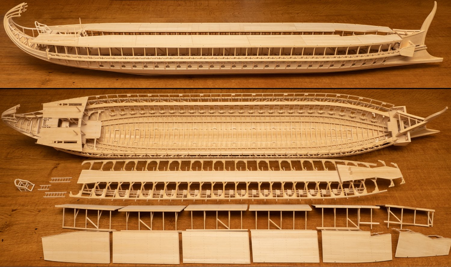
Disassembled the model today for the first time in a very long time, to check that I haven't done anything to stop me being able to get at the bolts and that the main hull outfit assembly (which includes deck beams, support pillars, inner hull longitudinals, gangway, and now thalmian seating...) is still removable.
It takes me just over half an hour to assemble (there are 82 bolts to secure in total...) and I was quite pleased with how easily the main hull outfit assemble fitted into place with no flexing at all and all the bolts perfectly lined up with their holes.
I'll have to do it again to fit the mast steps (I know, I could have done that before I put the deck in...) and I'm hoping it will make it easier to get at everything when I finally come to coating the wood with something.

-
-
On 7/3/2022 at 12:11 AM, Ian_Grant said:
Veering back and forth between excitement and hopelessness on this project. Fundamental issue is I do not have a lines plan for a Roman galley. They don't exist. I've always known this but now the rubber is hitting the road. I used Pitassi's quadrireme creation for fundamental length and beam measurements. His top view shows the profile of waterline and deck bulwark and that's it. Problem is that his tiny 4" drawing is hard to measure proportions from.
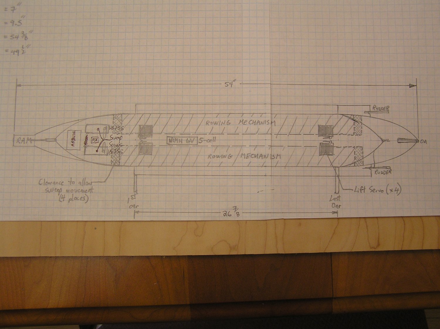
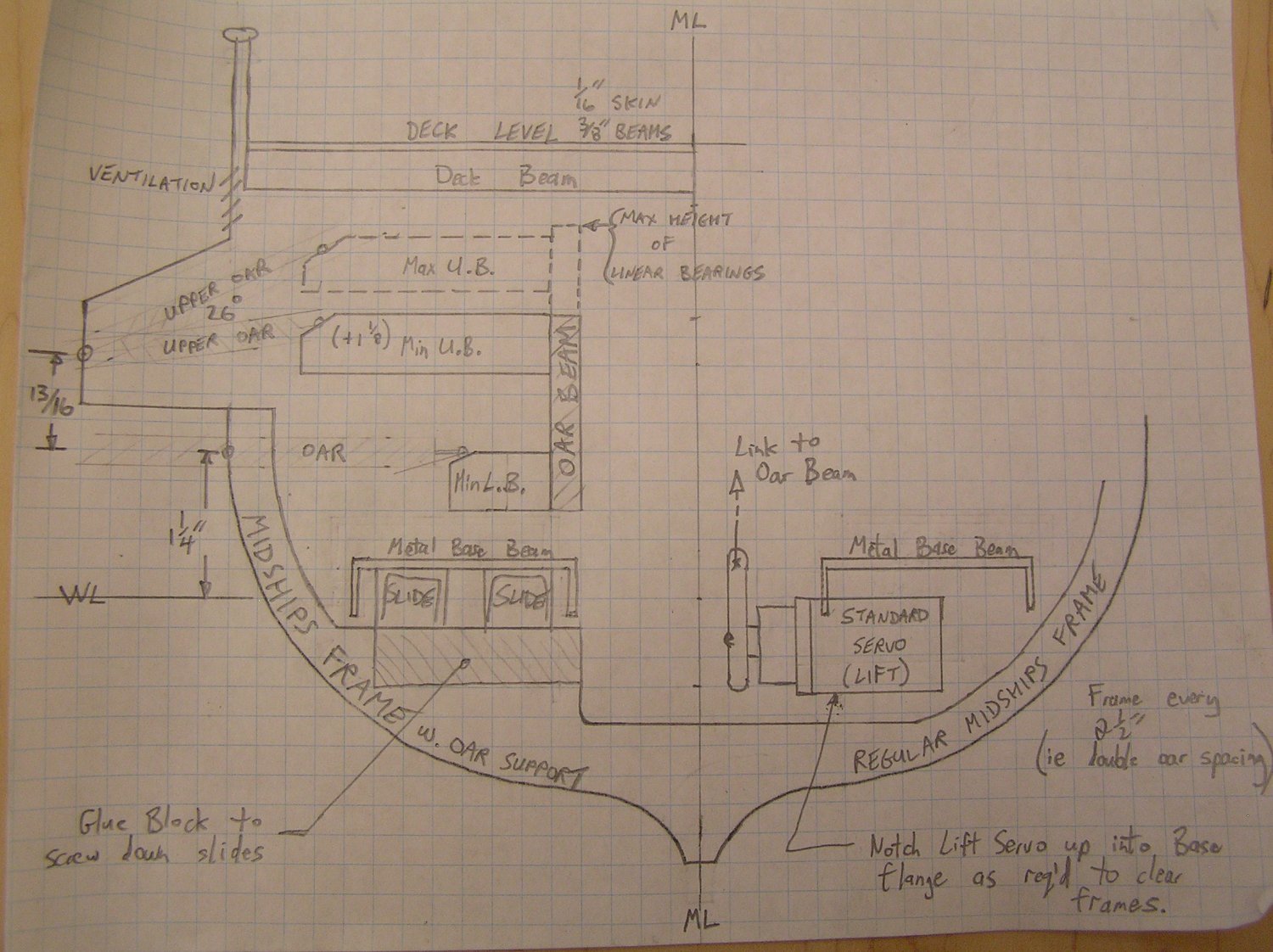
At 1/32 scale I came up with the general top view shown here, drawn at 1/4 size on grid paper. This was an effort to see if I am likely to have the space for all the electronics given that the rowing mechanism takes up most of the interior. It looks a bit tight in the bows for all the connectors sticking out perpendicular to the Arduino PCBs given the looming presence of the giant-scale sweep servos. I may stretch the bow out another inch or so. I've decided to use the Servocity low-flange beam for the bases of the oar beams, with the linear bearings to allow lift movement. I will however revert to the simple eye-screws to mount the oars onto wood like my earlier rowing test jig; no more u-channels and fancy pivots and hinges. As seen the oars require 27" of space, then there is a bit added at each end to accommodate the vertical shafts and linear bearings; then a "no-go" zone at each end required for the beams to do their sweep back and forth. The four lift servos will be mounted beneath the beam bases, screwed to them so they move along with them. I forgot to draw the rudder servo but there's nothing else back there and anyway I'm not sure yet how I will mount them or activate them. Probably will heed my old dad's advice and "don't try to figure out every detail before you start; solve the specifics as you get there".
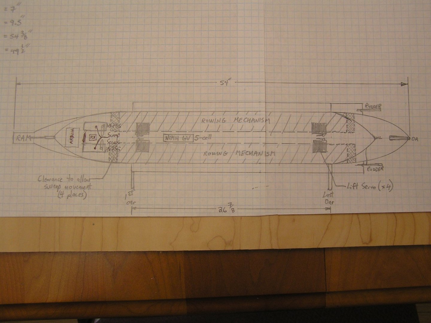
So now I know to extend the bows a little. Next was verifying there was space in the central cross-section to do the rowing. I really want a space along the keel to place ballast and the battery. Will be a 5-cell NiMH to provide 6V, and will need to be a "flat-pack" style not a "Hump-Back Pack".
The cross section I came up with has an 8" waterline beam which is a little beamier than Pitassi's estimate at 1/32 scale. I got that by enlarging the Olympias midship section drawing, and modifying to a bireme with my desired freeboard and my made-up deck level. Here is the result. Left side shows the oar beam placement and the outrigger for the upper reme. The slides are only 17" long, placed at the centre of the beam. This leaves nothing at the ends to get in the way of the lift servos as shown on the right. Clearance is a bit tight for them; I've shown it notched into the side flange of the metal base beam, or I could omit a frame in their locale. By the way, frame spacing will be 2.5", or double the oar spacing. There is ample room in the centre for the 1" wide battery pack.
Tricky part will be constructing the outrigger. I need to somehow provide some sort of framing to reinforce it, without interfering with the cycle of the upper oars. Not a lot of latitude for members. I will have to rely on the plywood bottom face of the outrigger to hold the lower hull's edge in a straight line above the upper oars since no cross-beams can be added to the hull here because of the mechanisms. Just how to make this outrigger solid enough to support the removable deck is another question. I did allow for 3/8" beams for the deck itself.
Worried I have too much of the hull under water...but if waterline drops so must oar mechanisms then I'm in trouble with clearances...🤔

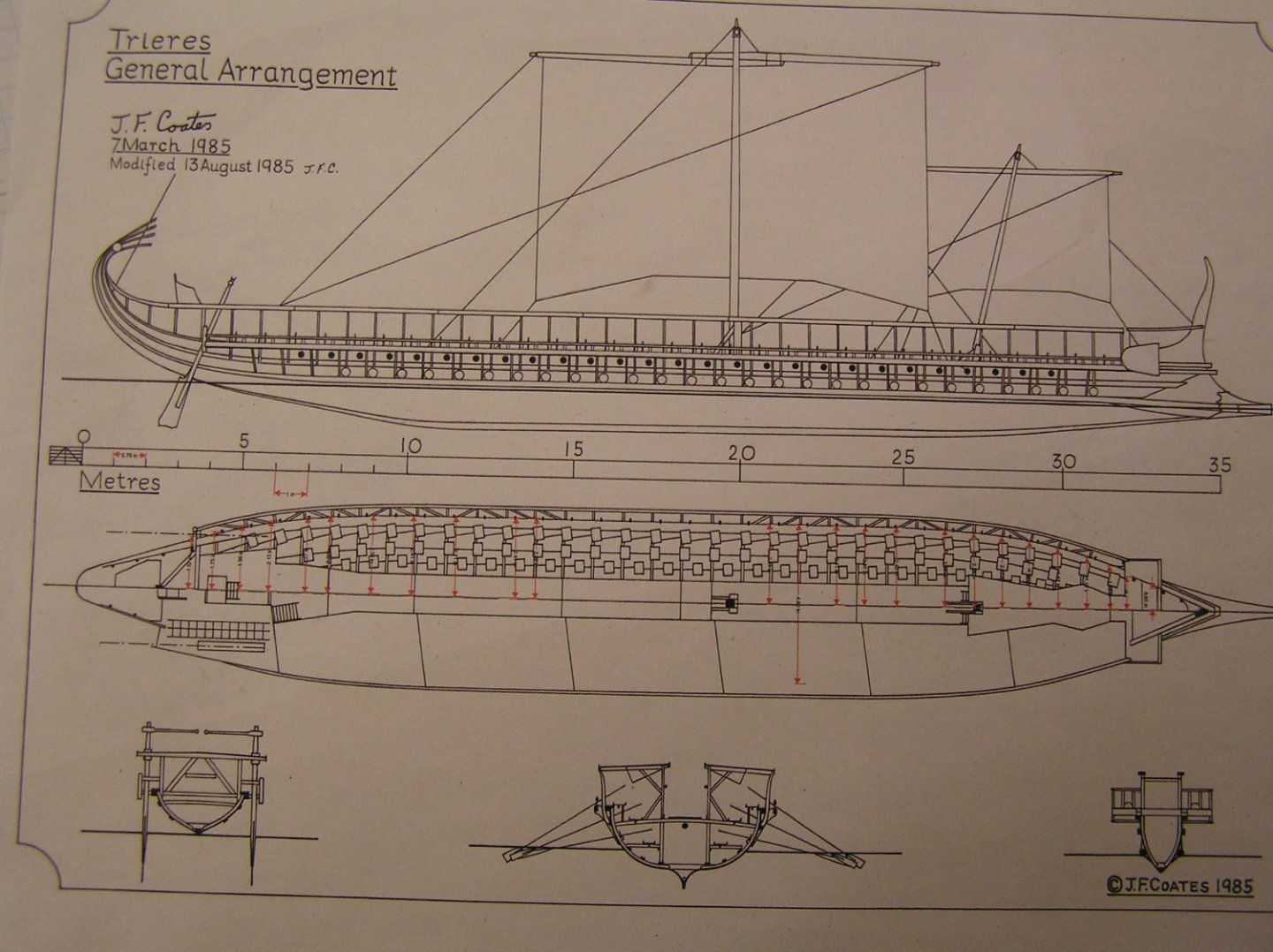
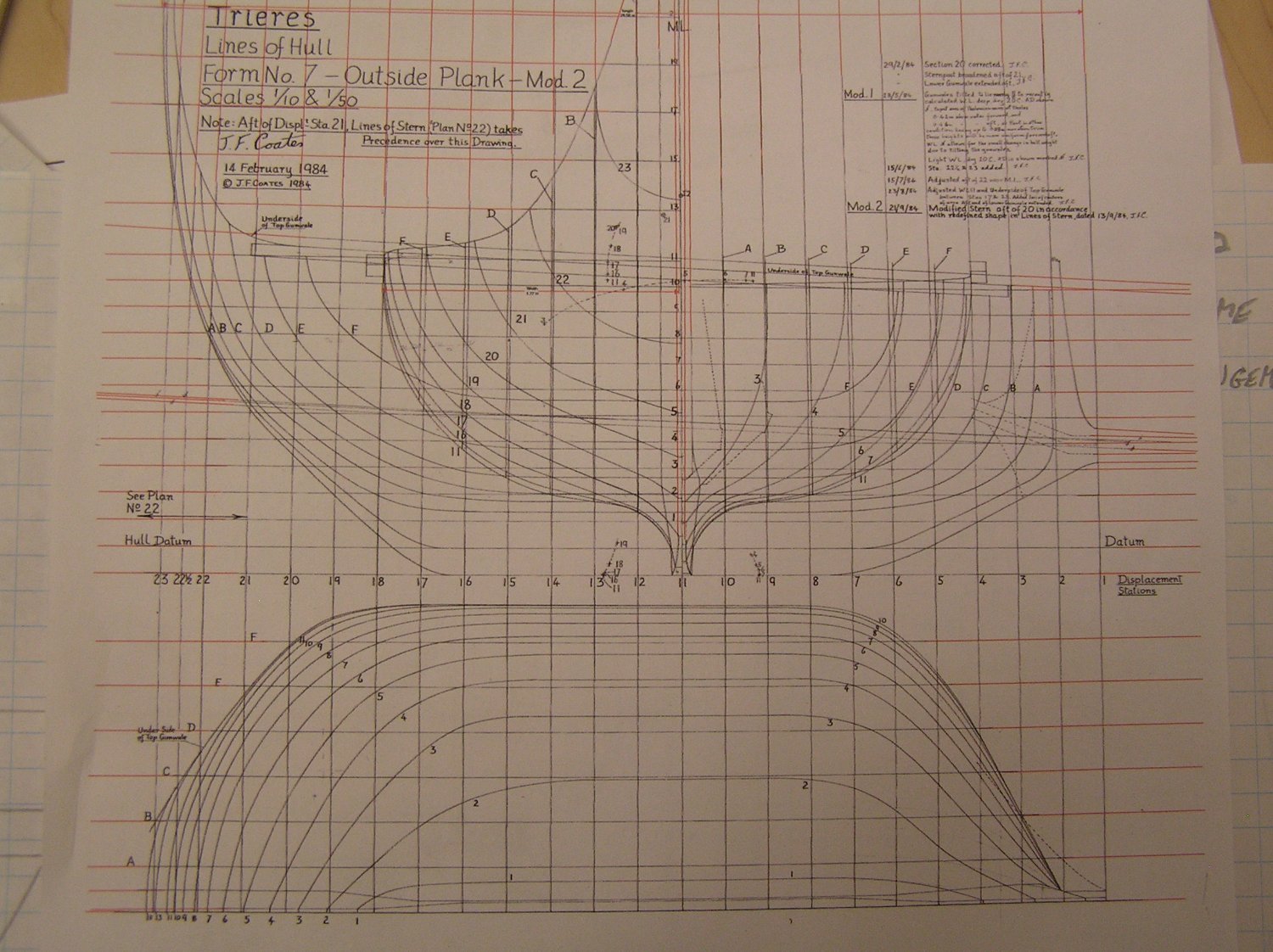
Lastly, hull lines. All that is available is the drawings of trireme Olympias. I expected them to be much like other lines plans I have seen but after downloading I was shocked to find the following:
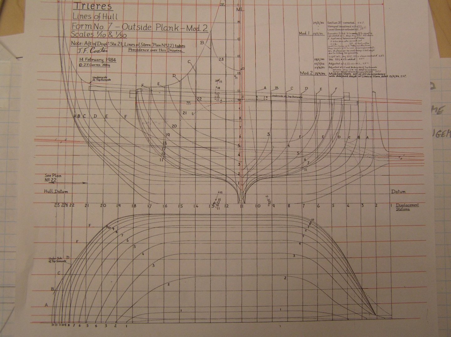
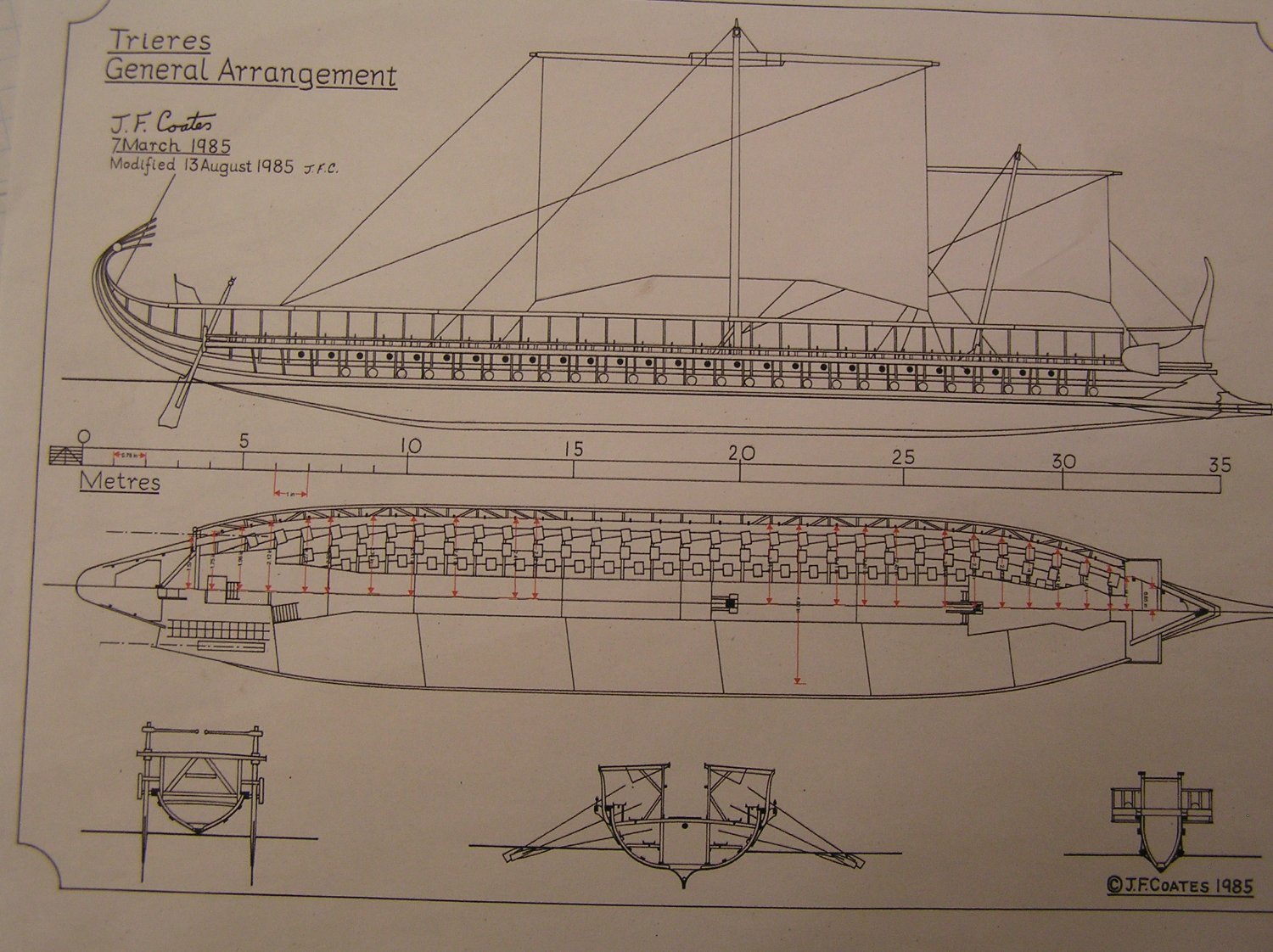
He seems to have the cross sections, waterlines, and buttock lines all on a single sheet with the sections drawn right on top of the buttocks. Never seen that before. And I cannot find any indication of station placement and spacing in the general arrangement (below). Kudos to Richard Braithewaite for deciphering these for his model. I will have to scratch my head; I wish I had my old drafting table and arm. I need to tweak the bow and stern to my made-up waterline to get ram and rudders correct, and stretch/compress them to my desired lengths. 🤪 I expect I will have to do a card mock-up to verify the lines are anything like correct.
Confusingly, this lines plan is drawn to two different scales. The sections are at 1:10. However the waterlines and buttocks are both drawn to 1:10 in the vertical (in the case of the buttocks) and athwartships (in the case of the waterlines) directions BUT at 1:50 in longitudinal direction. I guess John Coates did this so that he could fit the drawing (with a decent size for the sections at 1:10...) on a shorter piece of paper. The drawing would be over 3.5 meters long at 1:10...
Some of his other drawings give the locations of the station placement in relation to the structure of the ship (eg Plans 8,10 and 11)
-
On 7/7/2022 at 2:28 AM, Ian_Grant said:
Yes I have seen a video of a similar design, but the circular stroke is very inefficient and silly looking. If I can't have software-controlled rowing where I can alter oar dynamics as I please then why bother going further with this project....
I designed a simple prototype rowing machine that produces an elliptical rowing stroke. The machinery fits underneath the gangway on a 1:24 model of Olympias (in between the vertical stanchions). there is a link to a video of the machine installed in a 1:24the section of the ship on my Trireme Olympias thread on this site. Adding a software controlled stroke, as proposed here, would be really interesting as it would give you complete control over the stroke geometry.
-
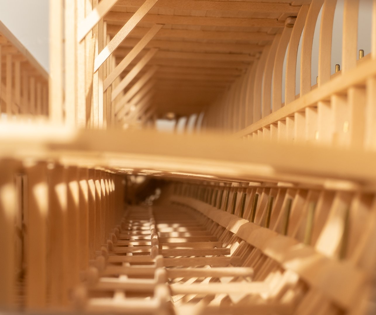
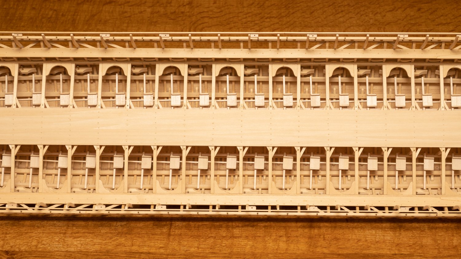
A Thalmian oarsman's view (looking aft) of the 21 seats Ive installed so far on the starboard side of the ship (149 to go...)
-
On 5/12/2022 at 8:30 PM, silverman834 said:
Very impressive build! And I love your wooden mannequin!
Regarding 3D printing roars men one way would do something similar to what I did in my previous build. I built parts of the ship in CAD and imported it in a program called Poser. There one can manipulate the mannequin to any position you want so it interacts with the CAD of the ship and then export and 3D print just the human.
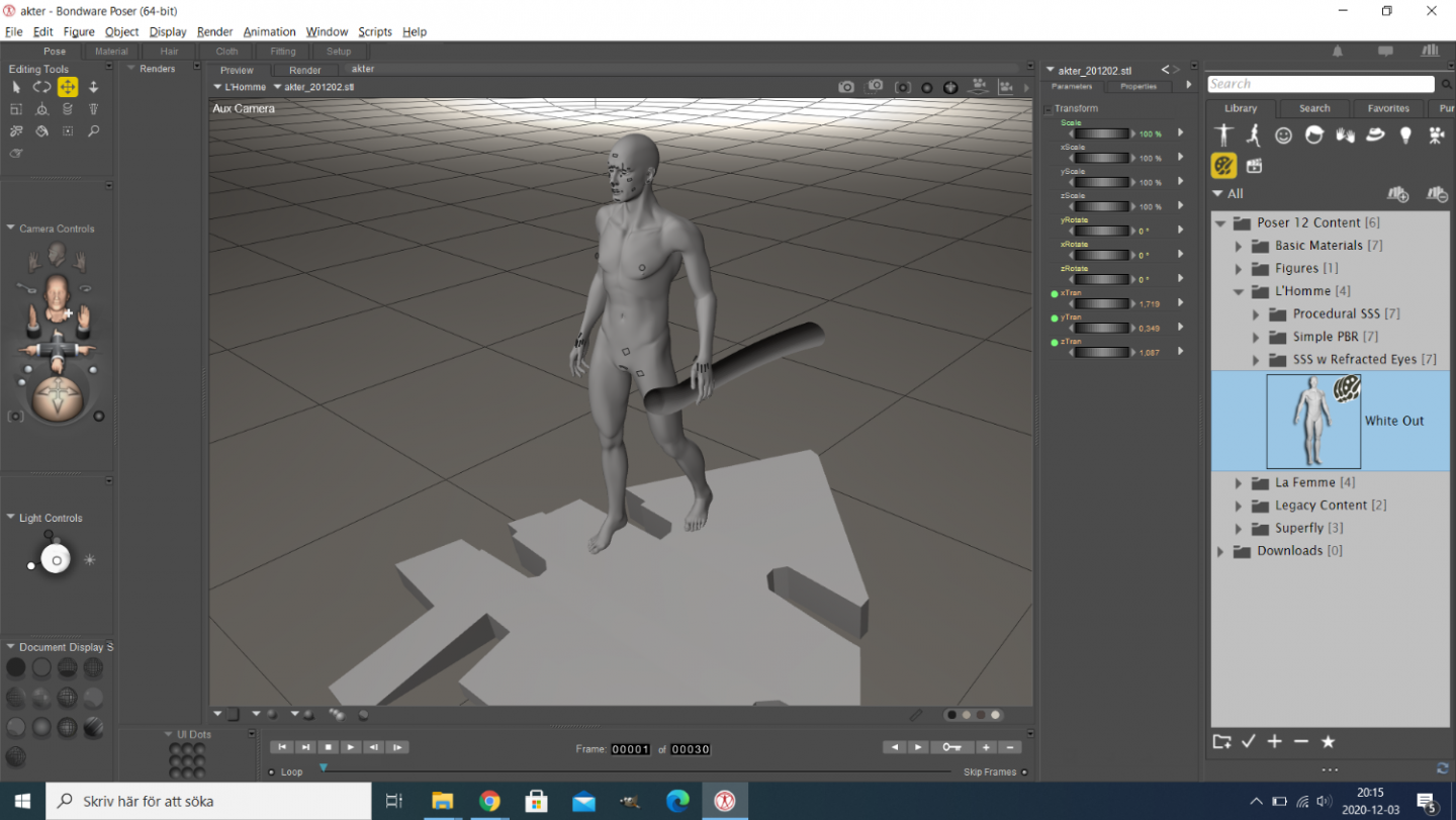
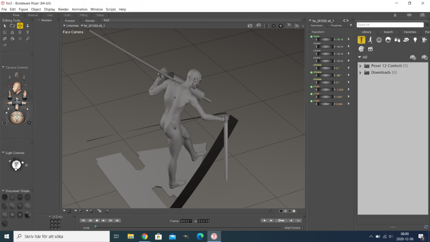
These mannequins are naked, but perhaps the roars men didn't wear a lot of clothes anyway so that would save you some time
Yes, I've tried some modelling of humans using a similar program that is freely downloadable (DAZ3D). I guess you could save in a file format readable by a 3D printer?
- Keith Black and mtaylor
-
2
-
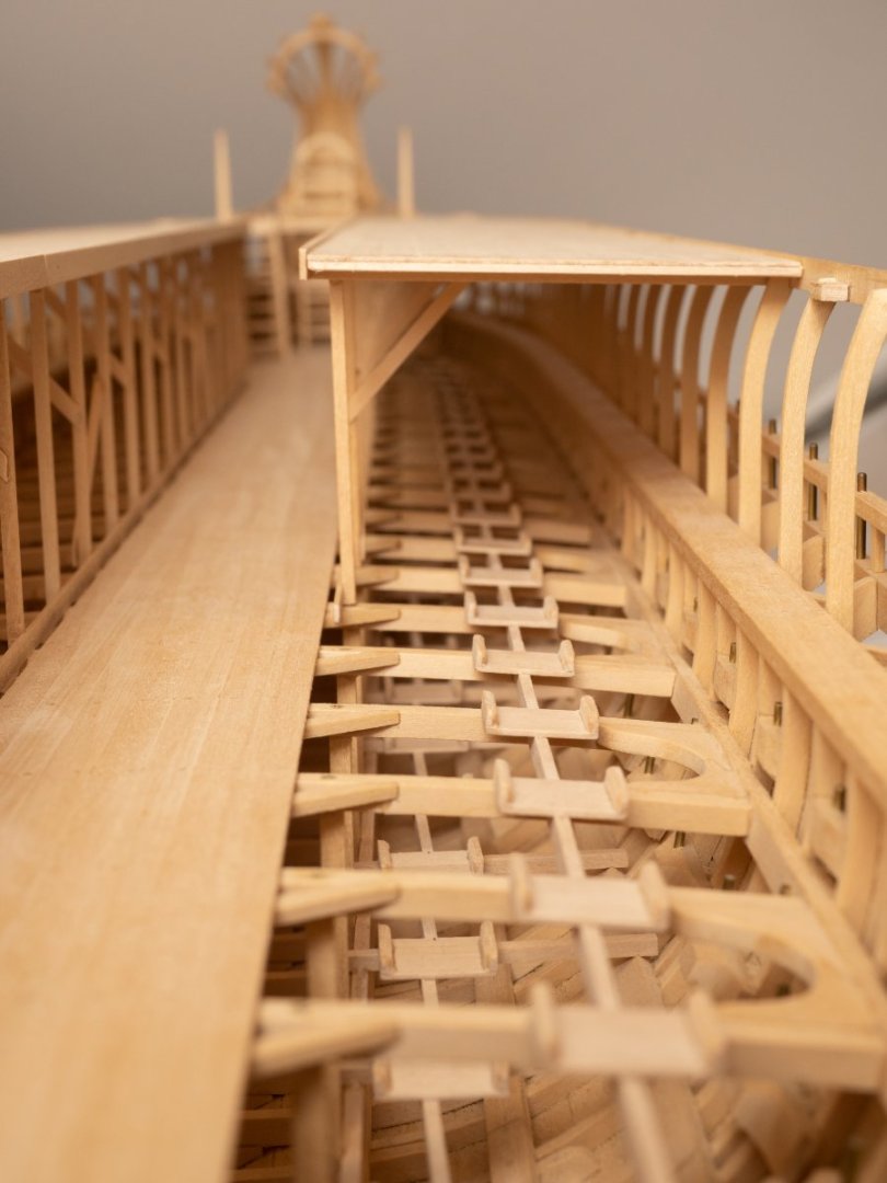
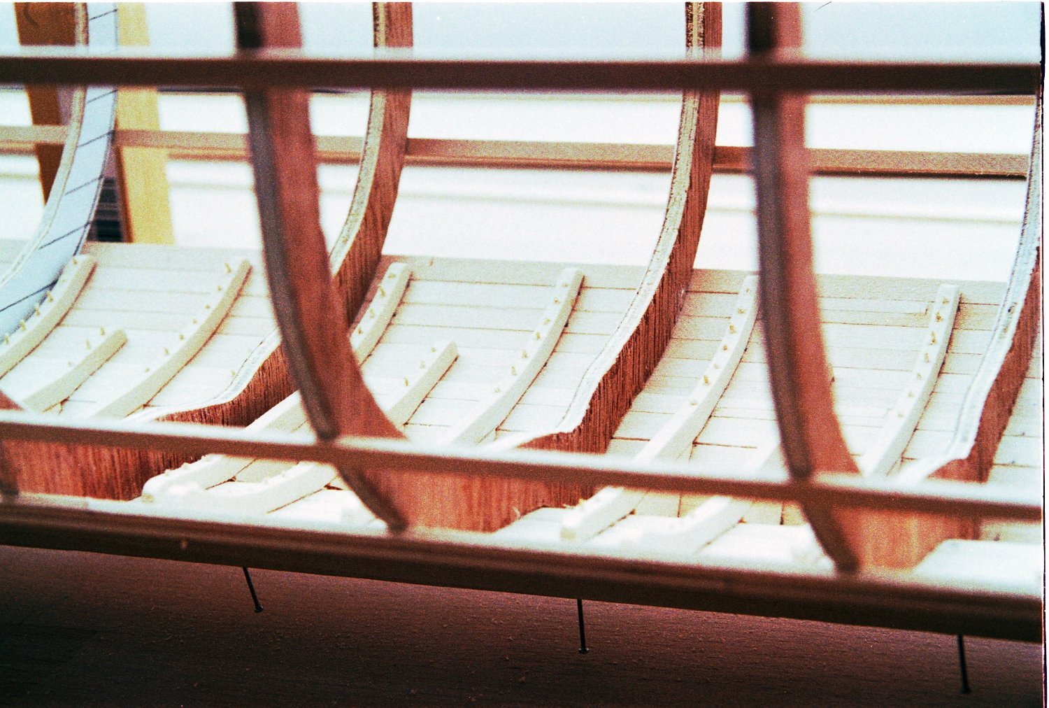
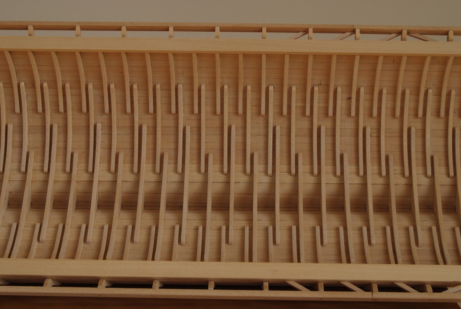
Great to see someone producing a model based on another of John Coates reconstructions!
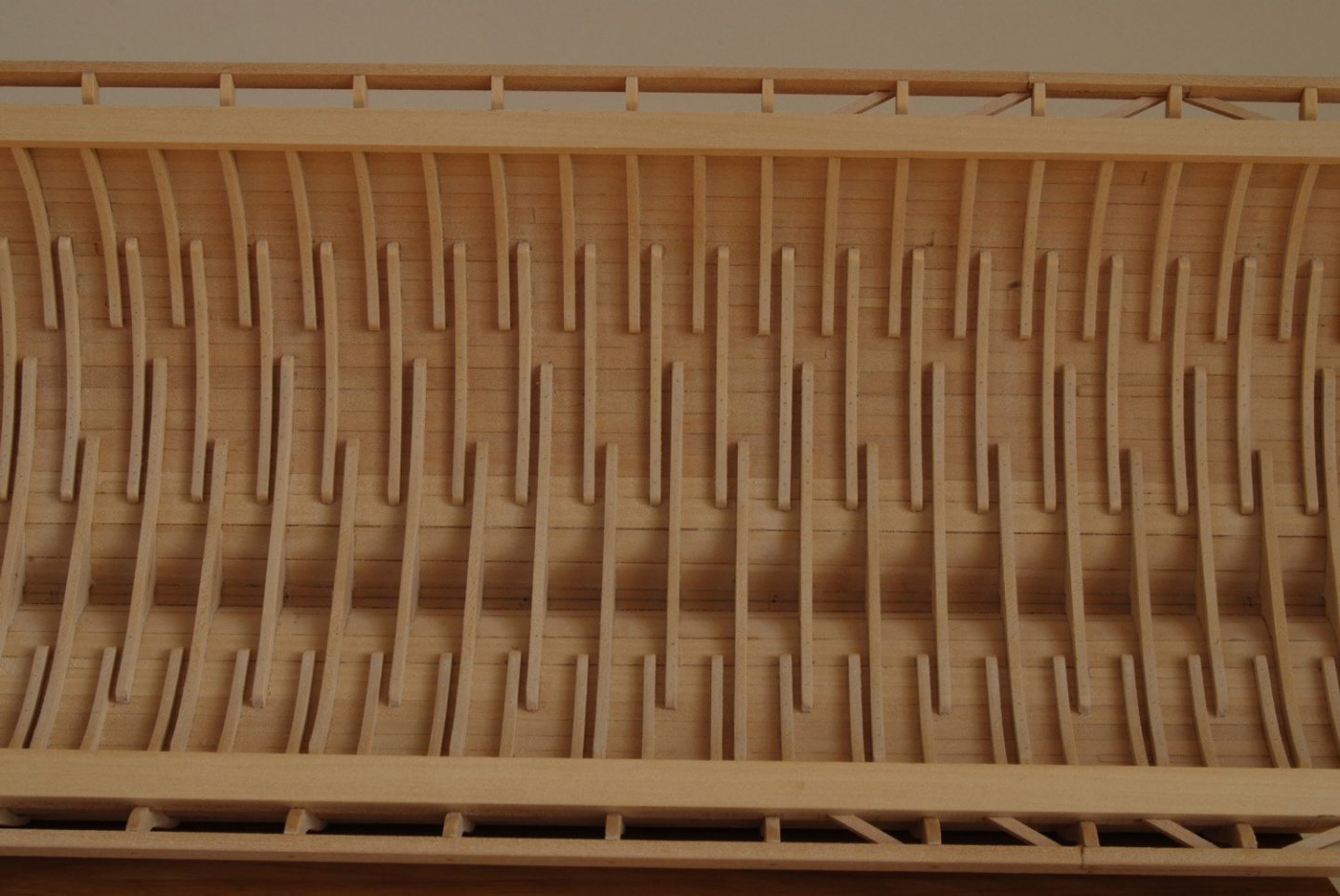
Building frames first and then planking them seems to work fine.
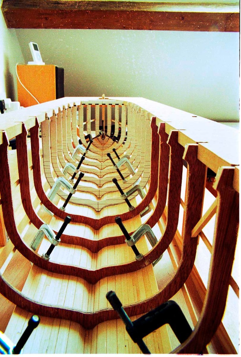
I produced my trireme hull the other way round...
Planking first onto a jig of temporary frames at the hull stations. Here is the hull planked up to the level of the floors:

And then fitting the frames from the inside
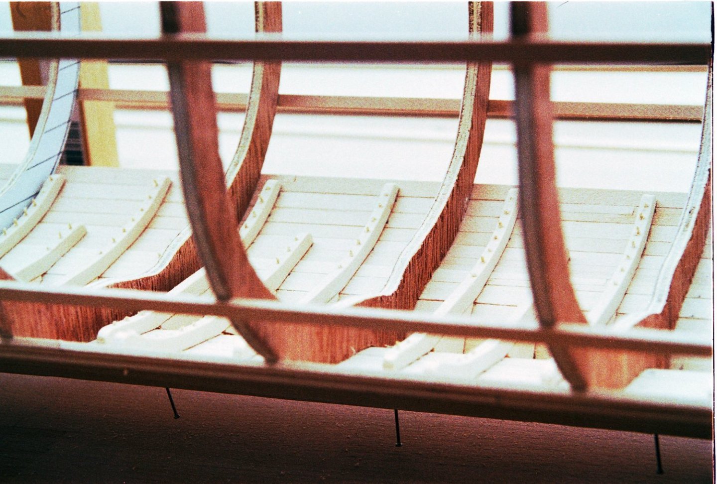
Working up level by level until all the planks and frames were in place and then removing from the frame jig:
- GrandpaPhil, Seventynet, mtaylor and 1 other
-
4
-
Upping the tempo on the Thalmian beams, stretchers and seats.
Here a Jig for installing the stretchers between the thalmian beams:
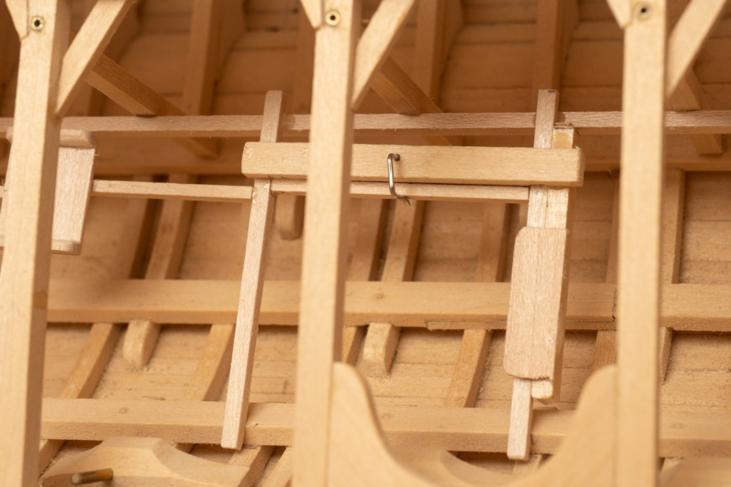
The little wire clip is useful in holding the stretcher at the right height while the epoxy cures. Unfortunately this jig will only work on the starboard side. I think Ill have to completely rebuild for the port side. Would have preferred to come up with something a bit more ambidextrous (oh well...)
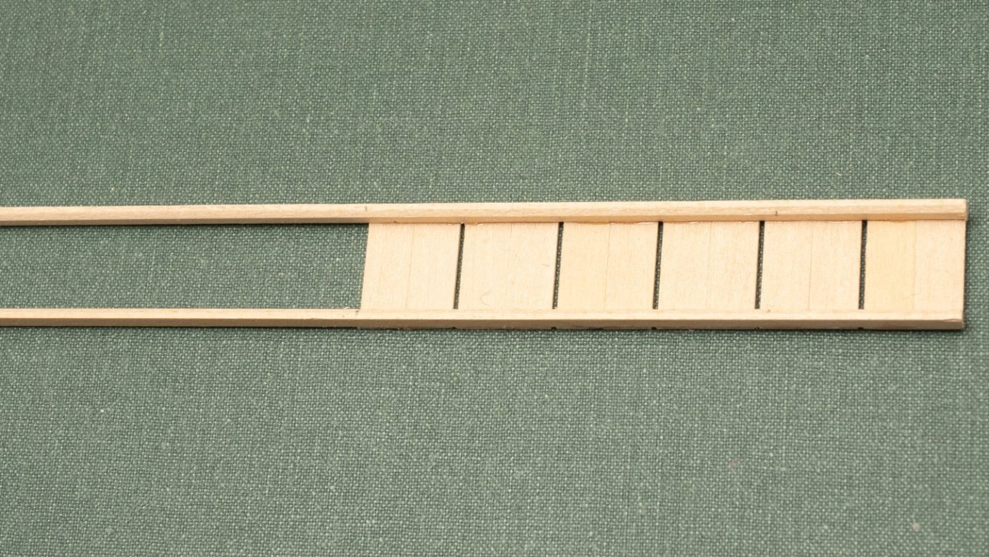
For the seats themselves, I'm building them in strip fashion so they can be cut off one by one and finished before installation...
-
12 hours ago, Louie da fly said:
The problem (as I'm sure Richard is fully aware) is that there were several values for the Ancient Greek "cubit", and the designers used the wrong one - which they only found out in practice. Had they used a larger value for the cubit the problem probably wouldn't have arisen, and in fact the literature on the Olympias suggests this as one of (many) issues to be taken into account if an Olympias II were ever to be built.
I had originally intended to make a similar little man to test out the rowing set-up for my dromon but never worked out the problems involved in building it. Very impressed, Richard, that you've done so.
Steven
Just looked through your Dromon Thread. Great reconstruction. I see you carved individual oarsmen! I don't think I have the endurance to make 170 for my model!
I am thinking of three of my manikins to demonstrate a single triad or oars. I suppose one could make a CAD model and 3D print them? Has anyone tried that?
- mtaylor, Ian_Grant and Keith Black
-
3
-
3 hours ago, Bedford said:
I found those diagrams interesting but as a rower I have some different ideas about it.
When rowing with others, ie a boat with 4 oarsmen, you come to learn how the physics have to work.
If the oars are already on the power stroke before entering the water you're wasting stroke power and putting undue stress on your body when they take up in the water. Ideally you need to learn to engage the water just as the power stroke starts so it's a much more pronounced plunge into the water than a gradual arc. This way the effort ramps up quickly as the stroke starts, more oar in water = more effort, but doesn't come on after you start the stroke if that makes sense.
The return stroke should be pretty flat, why waste effort raising the oar through an arc? The power stroke should also be fairly flat once the blade is fully immersed, diving deeper wastes power.
So I would suggest that the diagram of the movement of the oar handle is actually closer to the desired movement of the oar blade. Keep the directional arrows as they are but swap catch and finish, flatten the top of the stroke a bit and you've got a practical rowing stroke at the blade of the oar.
.jpg.85358ca601e190eca83276589eeaca2f.jpg)
I do take your point. Not the most efficient stroke...
Apparently the diagram was taken from a video record so should be reasonably accurate representation of what this particular oarsman achieved at this time. However, "the video record did reveal the variable quality of the bladework". Looking at the report which shows similar traces of what some of the other rowers were doing it appears that the diagram is one of the better ones (by a long way!). Bear in mind that this was 170 people rowing together for the first time in a vessel that they were unfamiliar with often from constrained seating positions with very little visibility. So technique was not optimal at all...
The report does comment on the large difference observed between the effective stroke length and the total length of the stroke saying that "the reasons why they mostly took their blades out of the water long before they had finished moving them sternwards require investigation.."
One reason suggested was that "the high moment of inertia of the oars which meant that they could not be manipulated quickly: if they were slowed prematurely because of this they would have to be taken out of the water early to avoid backwatering"
Even in a modern high performance racing 8 the blade is moving before it enters the water in order that it is at least travelling at the same speed as the water that is passing the boat (otherwise there will be a degree of backwatering at the catch and a negative force on the boat). For similar reasons the oar will be moving at some speed at the finish.
The distance taken to accelerate the oar to this speed before the catch ("catch slip") or decelerate it after the finish (the "release slip") will largely be a function of the inertia of the oar (as well and the strength/skill of the oarsman) as suggested in the report, and the oars fitted to Olympias were much heavier and had higher inertia than those of a modern racing shell.
They did make some effort to address this with lighter oars in later trials on Olympias. This did enable higher speeds to be achieved, but I haven't seen any traces of oar path to see if the catch and release slip had been significantly reduced.
There are some good diagrams at the following link which shows this effect and oar traces for modern racing shells.
http://biorow.com/index.php?route=information/news/news&news_id=30
even these guys seem to waste some energy moving the oar up and down in the water during the power stroke
-
This document contains a bit more detail on the trails and calculations described above and application to a working model of Olympias using the elliptical machine shown in the video on a previous page of this thread.
Rowing Machine Calculation.pdf
One interesting finding is that with The top tier only (i.e. 62 oarsmen) the average speed is predicted at 6.53 knots,
tis increases to 7.72 knots with all 170 oarsmen. So a significant increase in speed, but not as much as one might expect for all these additional oars. The main benefit would have been acceleration and maneuverability (very important in combat) which, I guess is why it was so important to pack as many oarsmen as they could into the boat.
-
7 hours ago, Ian_Grant said:
Richard, thank you so much for the detailed data on the stroke! Fascinating to study. I can see I have a lot of coding to do especially in details of the lift motion. I just started building a jig with a reme of 20 oars; plan is to use some sort of strain gauge to measure sweep force required to move blades in water. This equates to rowing with no response from the ship ie no acceleration, which will give me the maximum possible force. I've been looking at the Hitec HS-755MG and HS-805MG giant analog servos, hoping the 755 will serve because the 805 draws half an amp just to move its arm with no load (!). But we'll see what falls out of this next test. I'd rather have a big motor loafing along than a smaller motor labouring, provided the big motor isn't too power hungry.
As for the mechanism, I drew up some ideas using servocity structure and motion components. The vertical motion will definitely be linear bearings on 1/2" vertical shafts. My prototype oar attachments were crude, just a flathead screw left a little loose so the oar could tilt. I now plan to mount the oars in a u-channel which allows sweep movement only; the u-channel itself would have to pivot along its axis to allow the lift movement. I considered mounting shafts axially at the ends of the u-channel, said shafts passing through bearings mounted in pillow blocks, but that's a little pricey. The fallback is to simply mount the u-channel on hinges so it can tilt around as the beam moves vertically.
Again, thanks for the useful data. I'll need to improve the code defining the stroke shape, for sure.
By the way, there is a GPS "shield" for Arduino. Hmmmm.......
You can get strain guages for full size oars and I have thought about making a full size mockup of a single rowing position to measure forces to validate my computer simulation. However, it is probably impractical to measure the strain in a model oar shaft as the loads on the oars are really tiny.
For example the maximum thrust I measured in a zero speed trial of my Mk 1 galley (750mm long, 500 grams in weight, 12 oars, 150mm outboard length at 45 strokes per minute) was 0.0123N (measured using a fine thread attached to a post on the stern running to a pully with a hanging weight). So that's only 0.001N/oar!
The average speed achieved by this galley at this stroke rate was 0.09 m/s.
If we say that this galley was at a scale of 1:24 then this speed equates to around 2.16m/s or around 4 knots (if we scale speed by length). This isn't particularly fast, but then a constant speed circular oar motion is not particularly efficient!
The motor in my Mk 1 galley was way over the power required, but that's not really a problem (I wasn't interested in efficiency here) but it does ensure that any friction in the mechanism (much more significant than the propulsive forces) is easily overcome.
(Now if you fitted your rowing machine to a full size galley, or a really large scale model, the loads would be larger and easier to measure!!)
It might be better to measure the boat speed somehow and program your oar motion accordingly rather than try to measure these tiny forces?
Alternatively you could increase the speed of a small scale model, but that would require ridiculously high stroke rates!
Ive Just found a simple spreadsheet model that I used to predict the oar forces in the first trial (zero speed 45 spm) I referred to above:
And here is the spreadsheet set up for the second trial (steady state speed at 45 spm)
Since this rowing machine moves the oars at a constant (circular) speed no matter what the boat is doing its relatively easy to simulate with a spreadsheet. Still I was quite pleased at how close my spreadsheet came to the measured performance of my little model. Adding a human being into the simulation does, however, makes it a lot more complicated!!
-
On 2/16/2022 at 2:29 PM, Ian_Grant said:
That does sound interesting!
Working on Preussen for now but I can't get a galley out of my head. I think the sweep servos may be a problem as regards overheating; can't find any torque analog servos with metal case for heatsinking and I've seen too many videos with digital servos whining due to their internal CPU (!!) updating position at up to 400 Hz. Don't want the boat to whine, and digital servos burn more power. A servo with internal 32-bit CPU and 12-bit DAC may be de rigueur in an RC helicopter but seems ridiculous overkill to move oars at 30 strokes per minute......And their prices!!
Next summer I want to build a full mock-up to test force required to propel full remes of oars in the pool. Right now I have no idea what torque I need. Starting from full stop would obviously require peak torque, but I could start off at a slower & shorter stroke to limit total power.
Also thinking maybe I could buy a plastic analog torque servo and cut a hole in the case next to the motor to get access for metal heatsinking. Not sure if it can be done while leaving all necessary motor supports in place. Only one way to find out! 🤞
Once I know a torque value I can select a servo, buy one, and conduct thermal tests under load with a thermistor attached to case. Definitely need more data.
I did some trials with an early prototype rowing machine. If you go for a "realistic" stoke rate of say 50 spm the speed of the boat is very low (it can never be faster than the oars move through the water!) and the force required (and hence torque on your servos) is trivially small.
A more significant factor determining how strong your servos need to be will be the friction in your rowing machine mechanism.
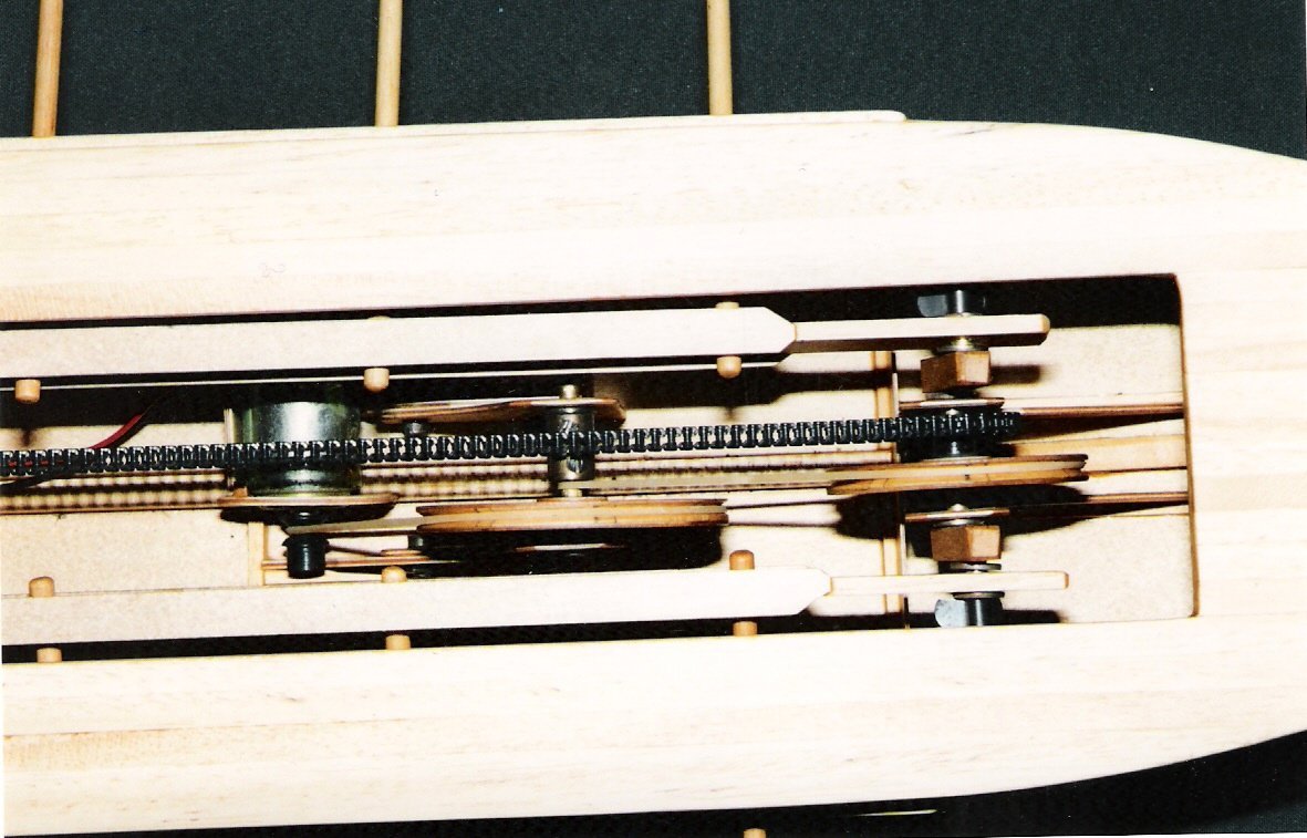
A couple of pictures of my Mk 1 Galley and its rowing machinery (simple, circular path, constant speed...).
I found, that as the scale speed is so low you need a really calm day if you do the trials outside!
My calculations suggest that this will still be the case with a 1:24 scale model of Olympias even with its 170 oars...
-
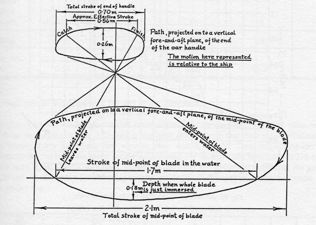
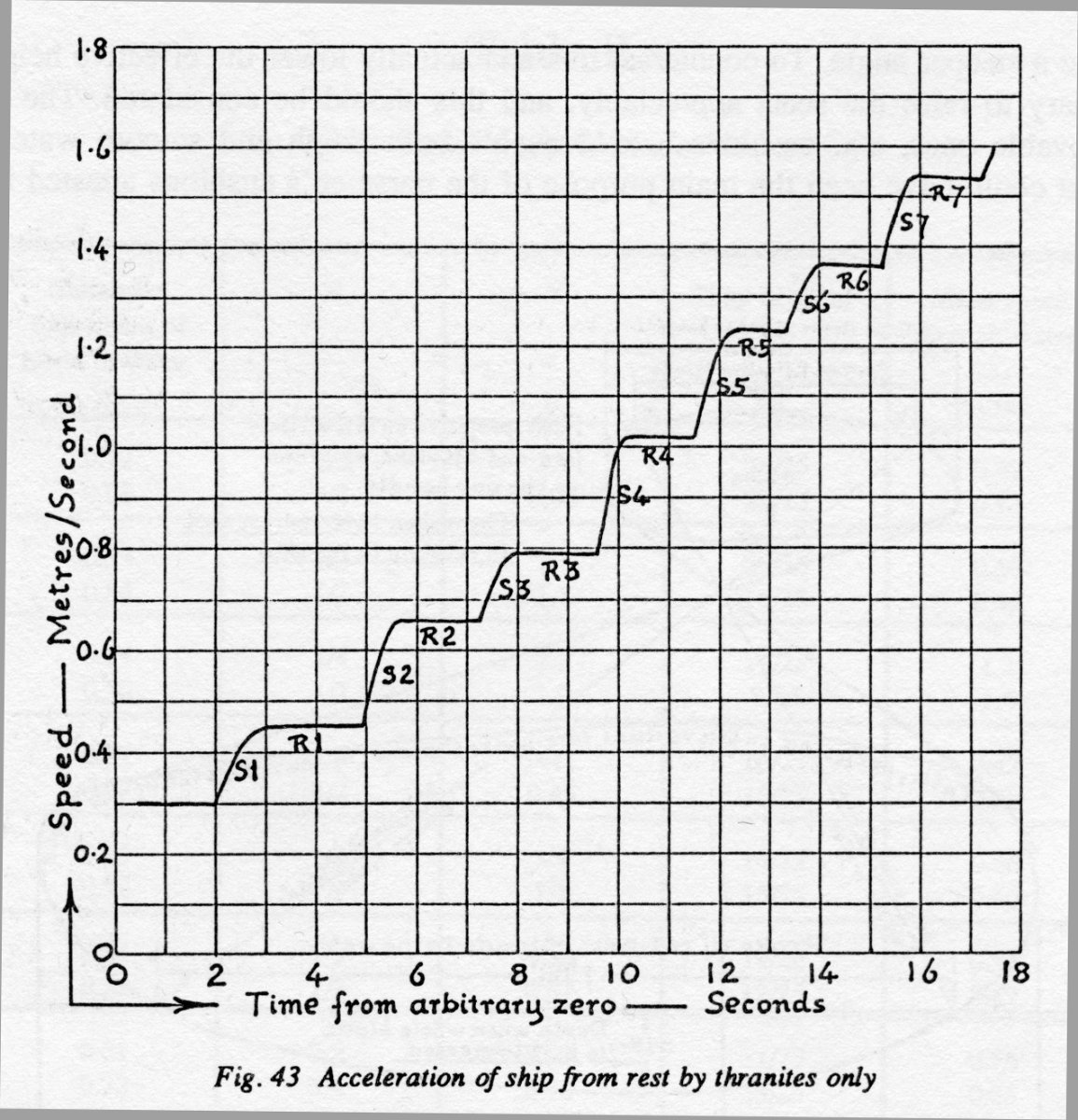
A couple of figures from the Olympias sea trials that may be of interest (Ref The Trireme Trials 1988 Report on the Anglo-Helenic Sea Trials of Olympias, J F Coates, S K Platis, J.T. Shaw, Oxbow Books)
The first shows a trace of the oar handle and blade of one of the Thranite oarsmen (top tier, who tended to provide most power as they had the least constrained positions):
The next plot is of speed from a standing start (Thranites only). Acceleration and maneuverability are particularly important for this type of vessel so that they could break from a slow moving formation faster than the opposing vessels and so achieve a tactical advantage and get into a position to ram.
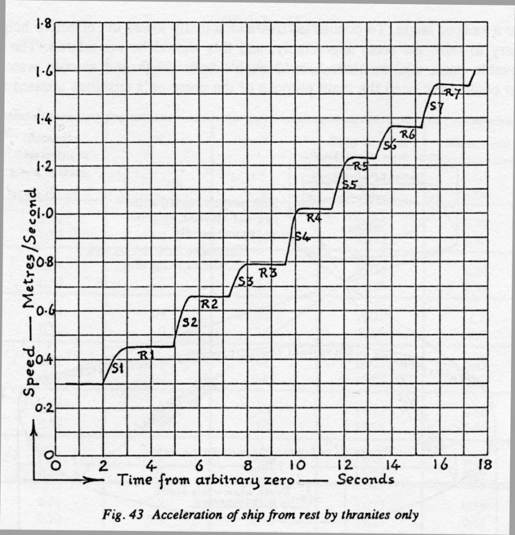
You can see that the first few strokes are at a lower rate, accelerating as the boat speed increases and the pressure on the oar blades reduces for a given stroke rate (at higher speeds the inertia of the oars will become more dominant in determining stroke rate).
My current simulation code allows you to set a maximum load that the oarsman can apply to the oar handle and then works out the dynamics of the oar handle (and the resulting forces on the boat) accounting for water pressure on the blade and oar inertia.
When I use the data for Olympias with Thranite oarsmen only I get the following match for the trials data:
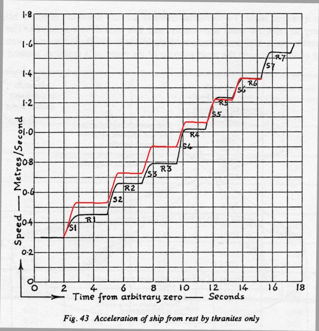
For a working model (it you wanted to make starts more convincing), you already have the ability to vary the rate of the power and recovery parts of the stroke. You might be able to add a sensor for boat speed (gps or spinner?) and adjust stroke rate accordingly?
I just noticed that this thranite oarsman achieved a 700mm stoke (the design hoped for 800mm ...), which is similar to the stroke length that my manikin figure is managing on my model (on the more constrained, lower level). I've just posted a GIF animation of him in action on my blog!
- Ian_Grant, GrandpaPhil and mtaylor
-
2
-
 1
1
-


Trireme Olympias by Richard Braithwaite
in - Subjects built Up to and including 1500 AD
Posted
Adjustable footrest in place..