Ras Ambrioso
-
Posts
603 -
Joined
-
Last visited
Content Type
Profiles
Forums
Gallery
Events
Everything posted by Ras Ambrioso
-
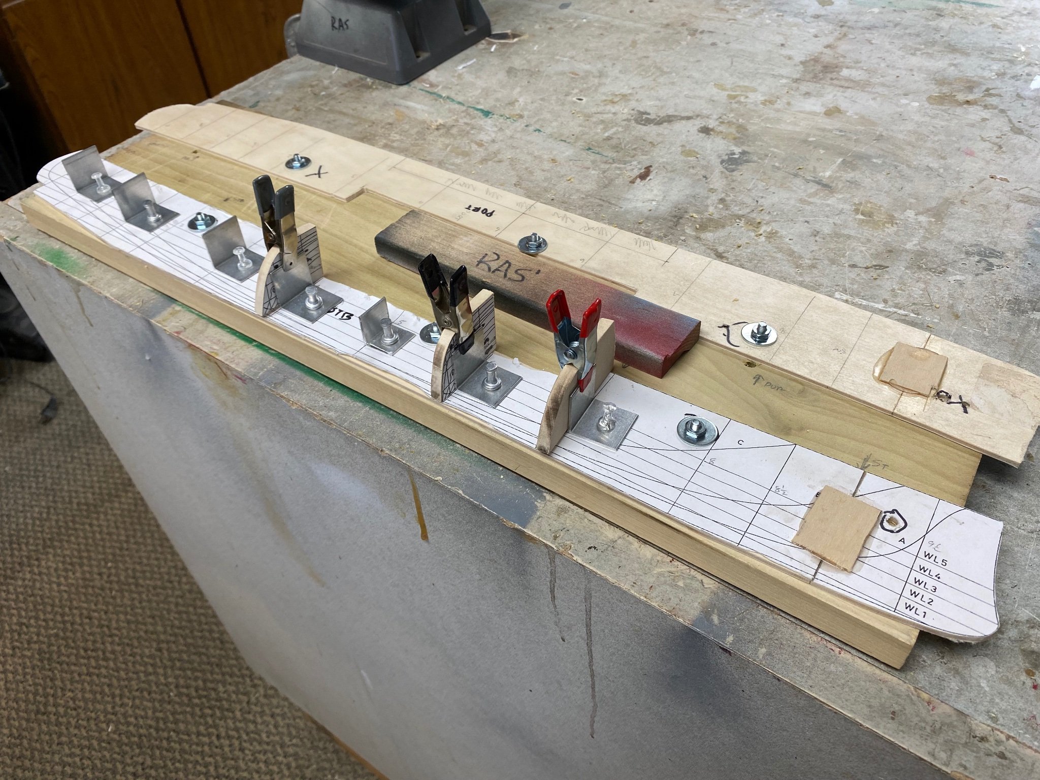
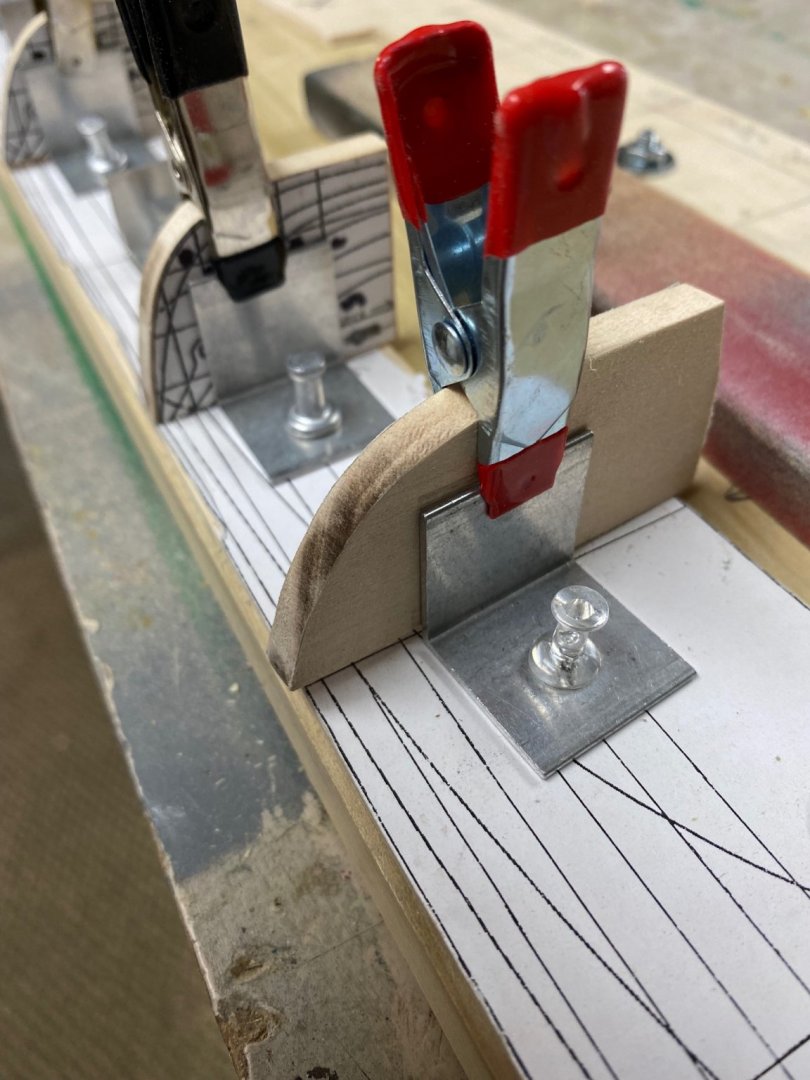
 A little progress. Finished matching the two half-keels and secured them to my work base. Dry-fitted some of the frames using the angle gadgets I got from Micromark. I only got 8 pieces in the package and I need 22. So I went shopping for an aluminum angle and some push pin and, voila, I got my 24s. I will use these dry fitted frames to determine my planking belts and, using battens, mark the needed bevelinf of the frames. My angles and the purchased ones.
-
Thanks Mark. I will sure do. And you give me an idea for the presentation. I have a lot of pictures of these guns in service in different navies. I could set it on a planked firing over the Bulwark. Great!
-
Now for the news. Amapá's keel, or shall I say half keels, had been laid after the "fifie" left the dry dock for commissioning. The half keels were attached to a building board and the bow section was glued in place. The roughly cut frames were dry fitted to the working board. The half keels still need to be trimmed. To do this, I will clamp the two sides together with screws using the board's attachment points as setting holes. This will make the two half keels identical. That way, when the frames are all in place, all I need to do is to remove the half frames off the board and join them together. The result is a fairly thick keel but, who is watching? Following the advise from Toni in other posts I intend to do the fairing and the planking while the half keels are fastened to the board. I have been researching the 1/64 scale Hotchkiss QF firing gun mounted on the forward deck of Amapá. Since I also like to build miniature guns, I plan a little side project to build a 1/24 scale model of this gun under a separate post. And yes, I intent to post the build in the non-ship category if it is alright with the administration. This will be a metal model with a lot of lathe and milling machine work. Thanks for following.
-
Roger: Thanks for the information on the shellac. I am very familiar with Kiltz since I have used on the ceiling of my previous home. W ill try it out soon. Thanks again
-
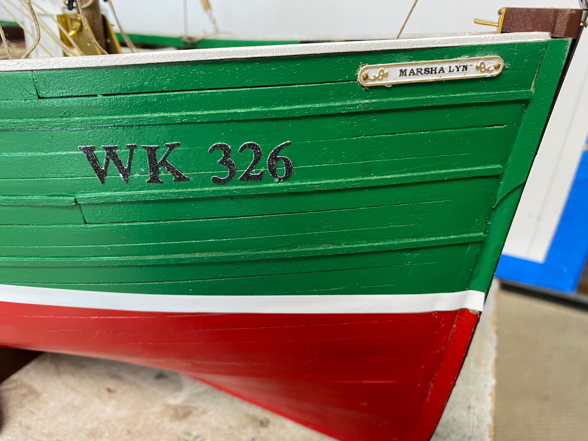
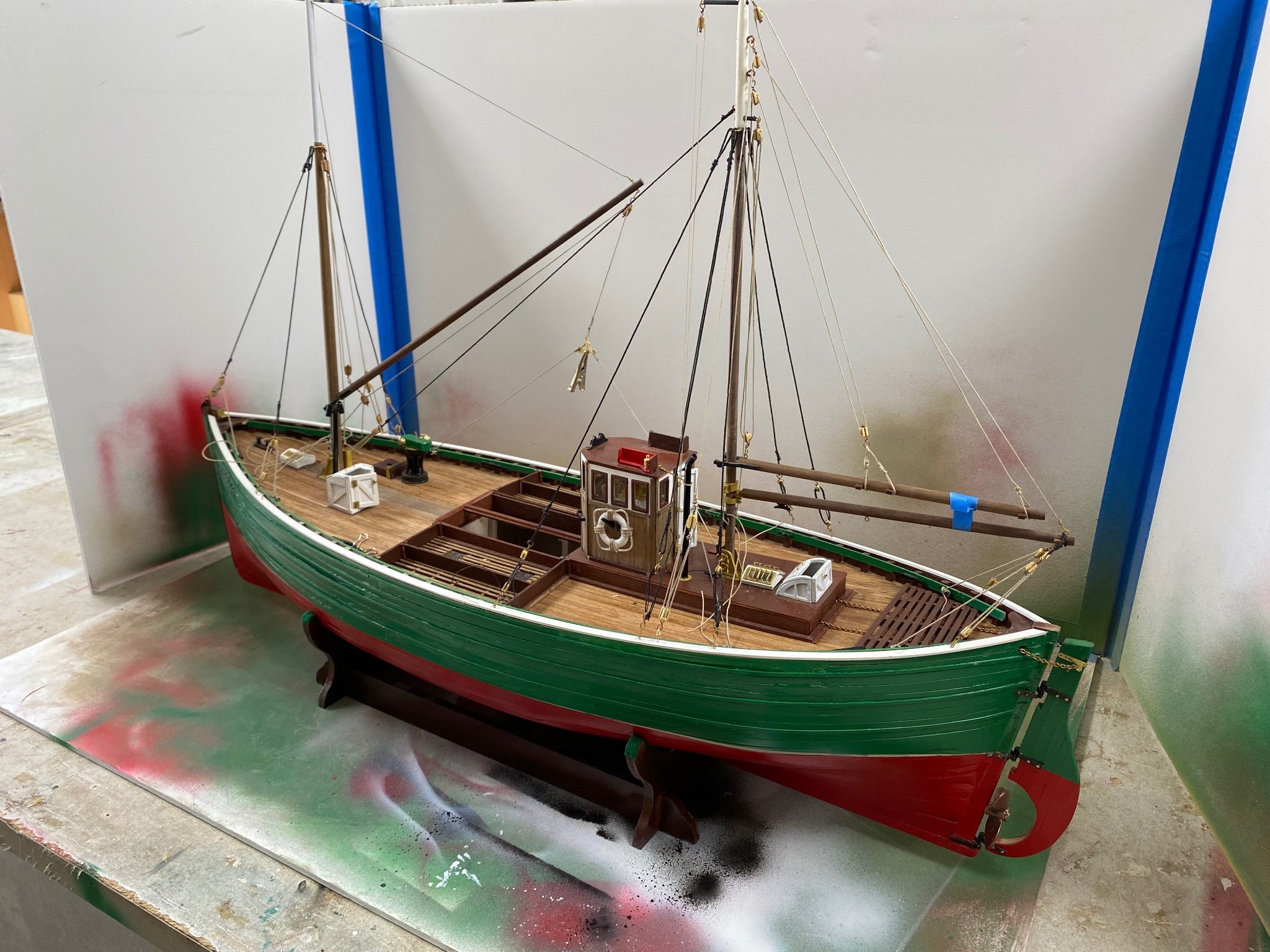
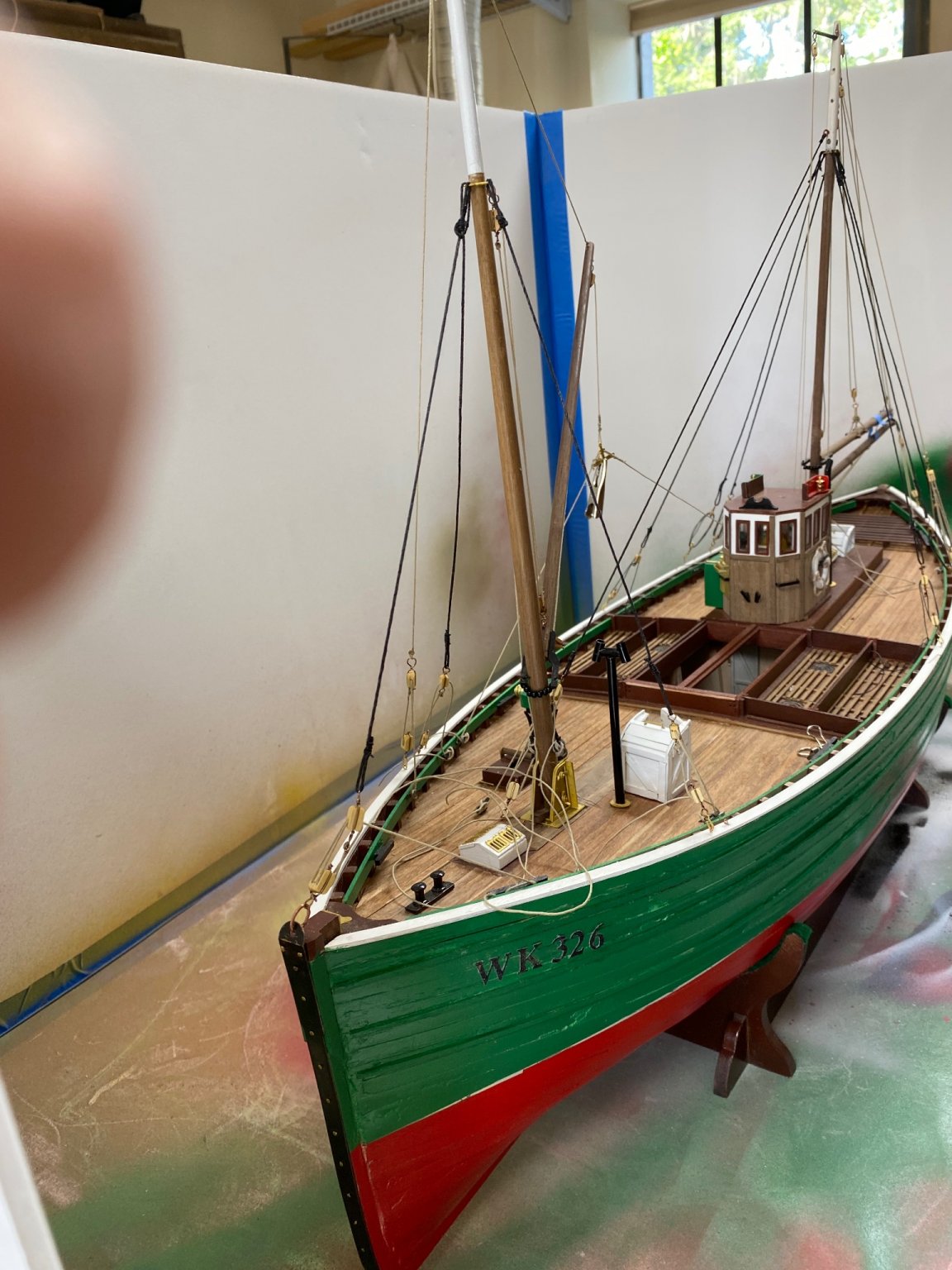
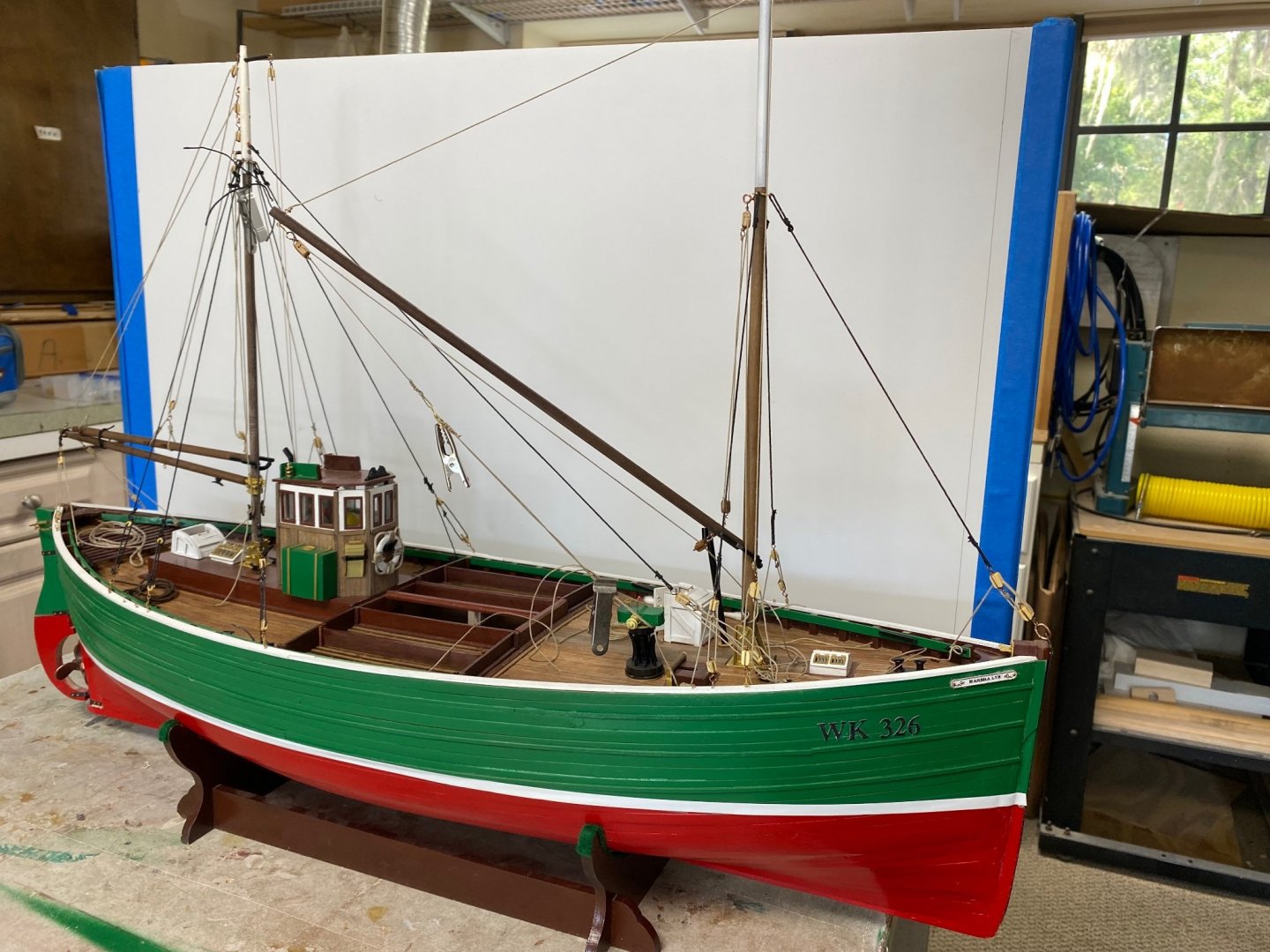
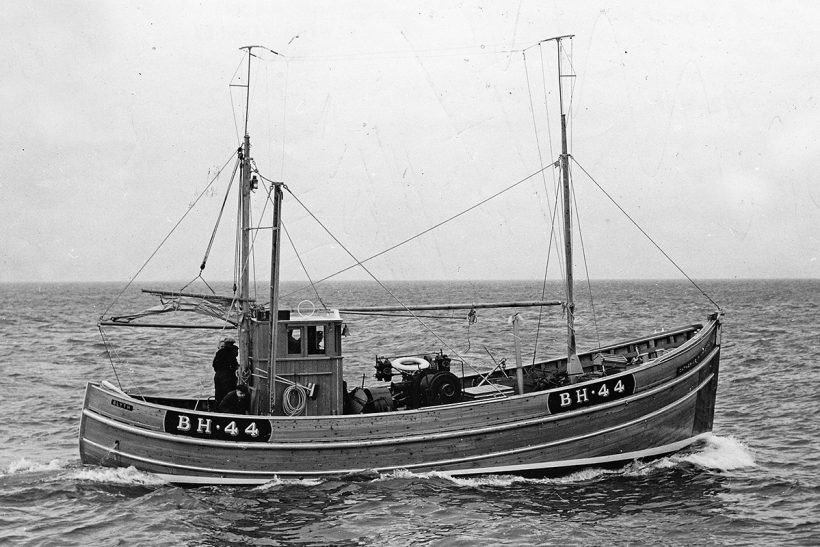
The ship has all of its rigging installed (except the sail) and will leave the dry-dock to complete its commissioning. There was a little ceremony, but I couldn't find 1/32 scale champagne. I had a beer instead. The ship hails from the the port of Wick in NE Scotland (WK) and its number was my employee number in three of my work places. One of them was for an American company on Cuba at the age of 19. All my employee numbers ended on 26. Is that a coincidence, or what?. The fifie is named after my dear wife, the Admiral, who patiently waits for me to also do the apartment chores. After a short rest from this build I will return to complete several deck details including the crew. See you then. Now, on to Amapá

-
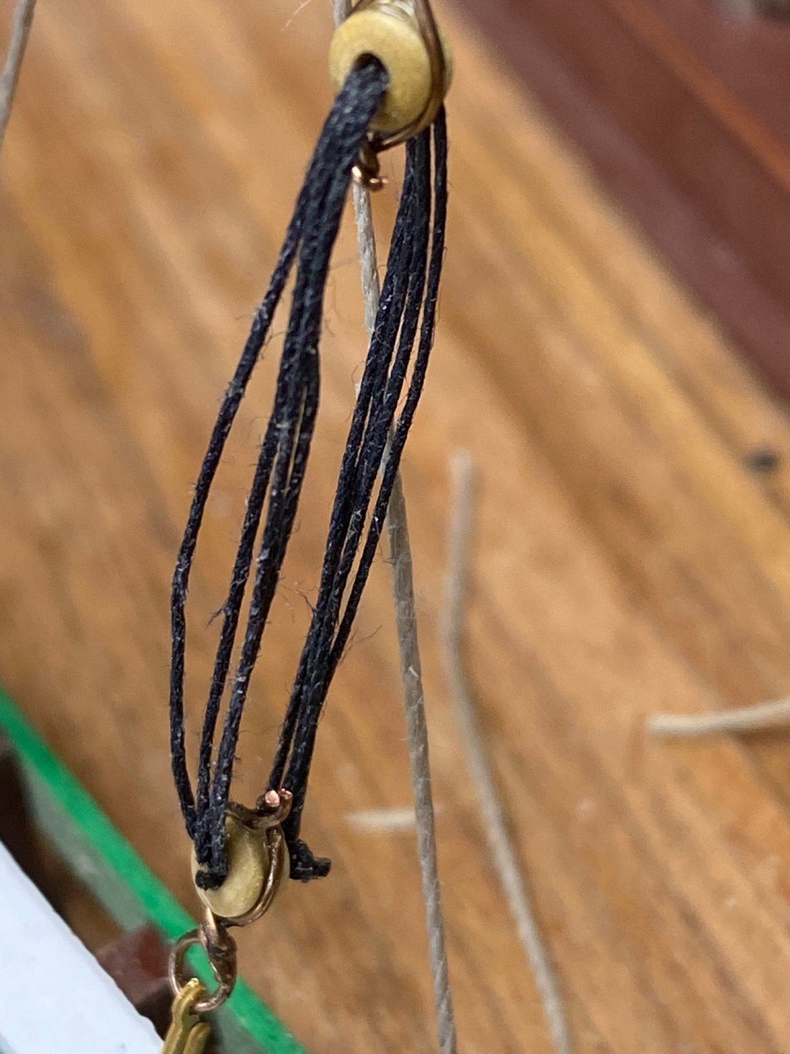
Continuing my fix of the aft mast stays, today I completed the port side. The rigging of the bullseyes is not as per the kit's plans but it made it easier for me, with my shacky hands and poor depth perception. Tomorrow we will do the starboard side and rest for a while. I need to buy a smaller pair of scissors to be able to cut the knots closer. One more tool to add to the pile. In our shop, the work bench is 8ft long and, when I am working, I have it full with my stuff. Other residents that pass by and ask me why I need so much stuff to make such a little parts. I will be taking a week off Fifie to work on my other project Amapá. Thanks for following me.
-
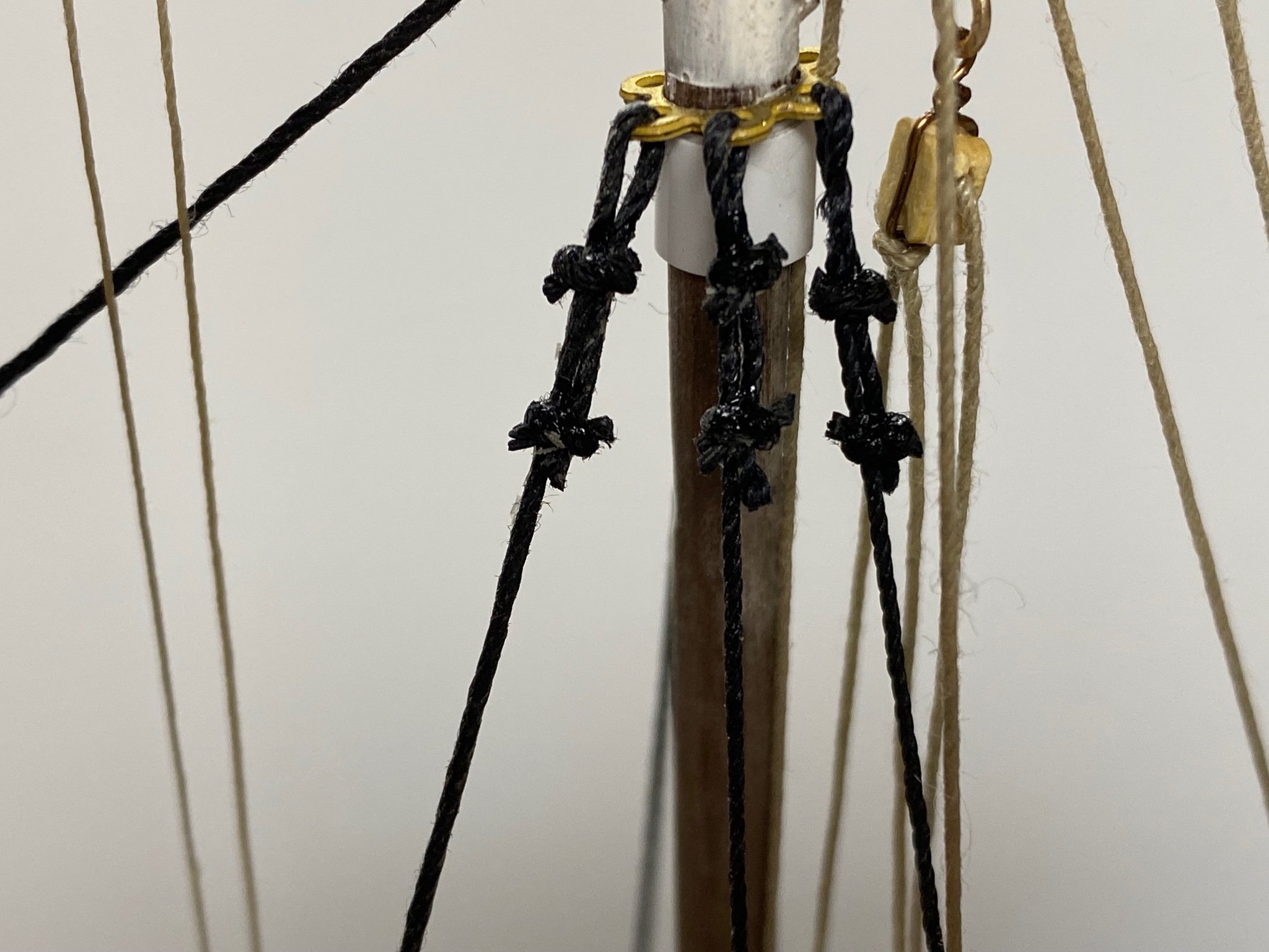
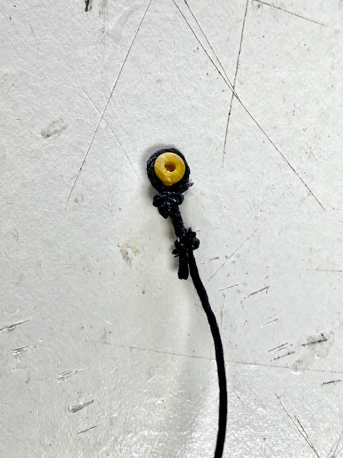
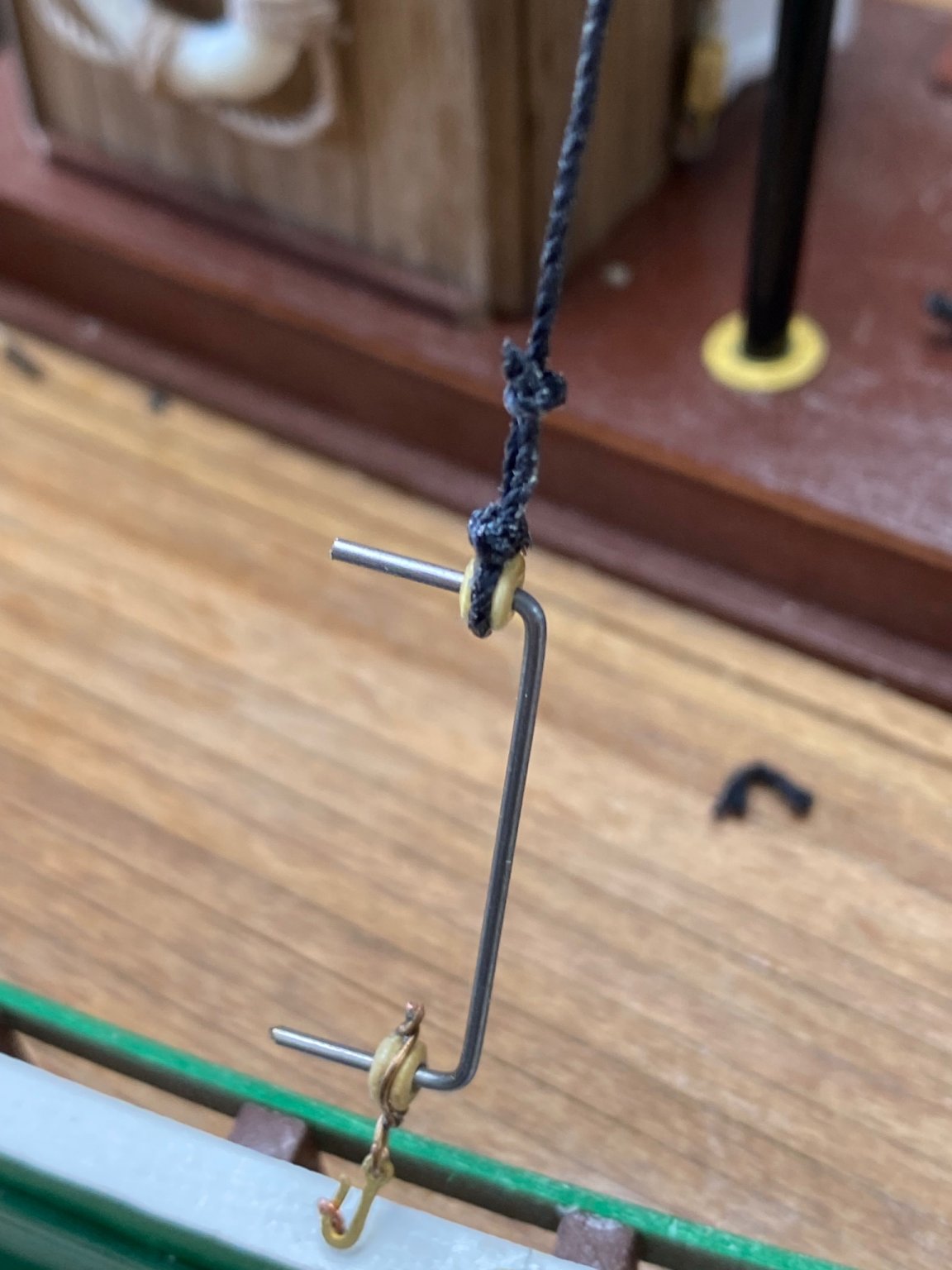
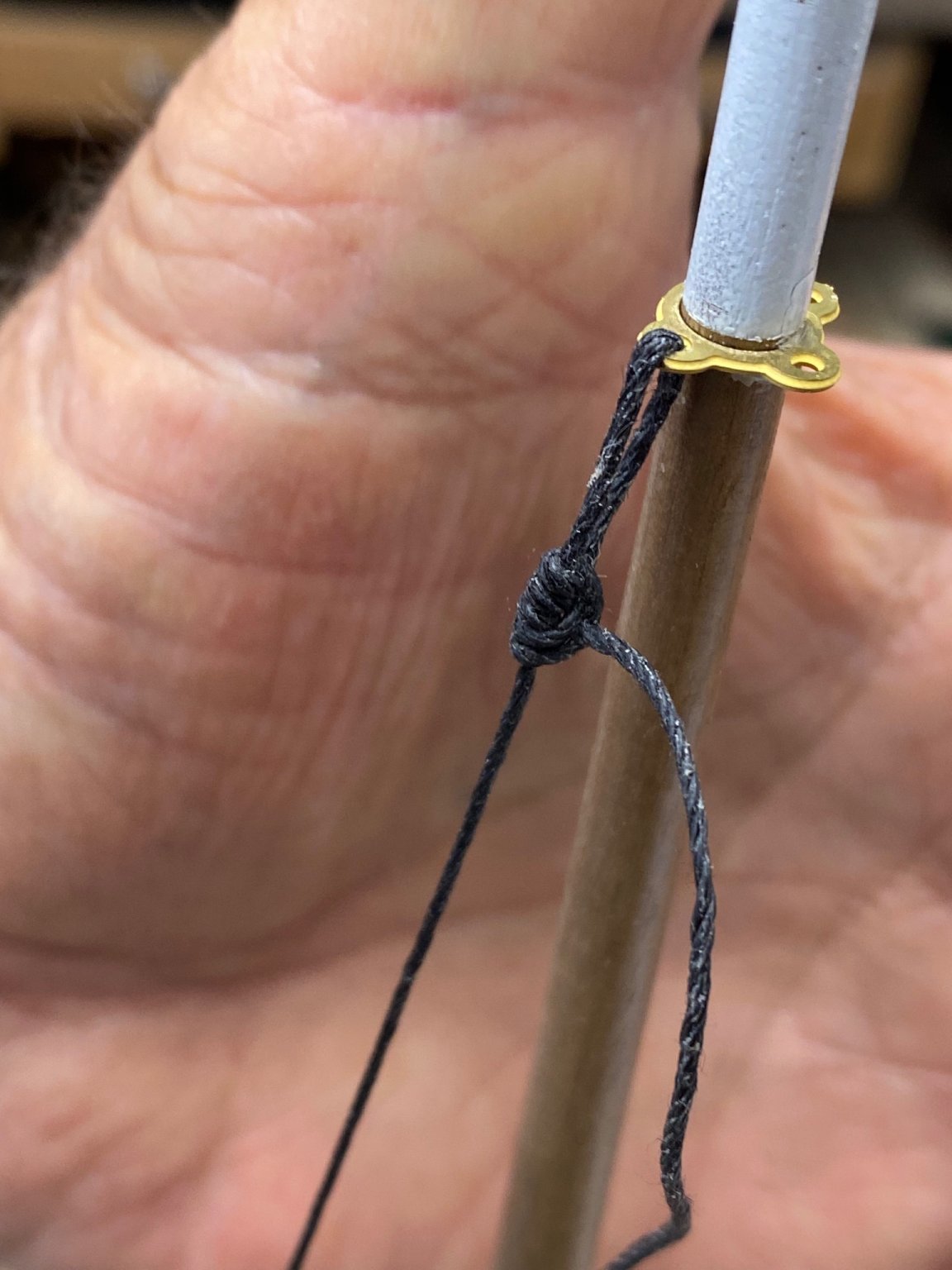
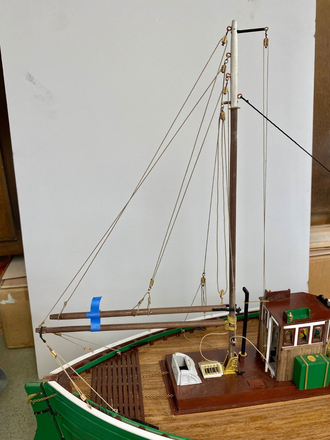
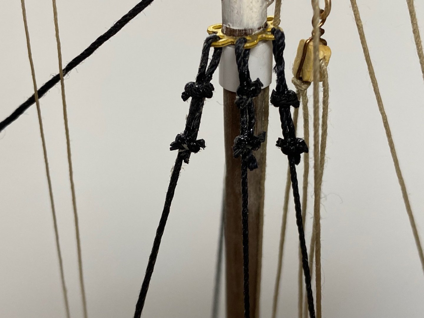
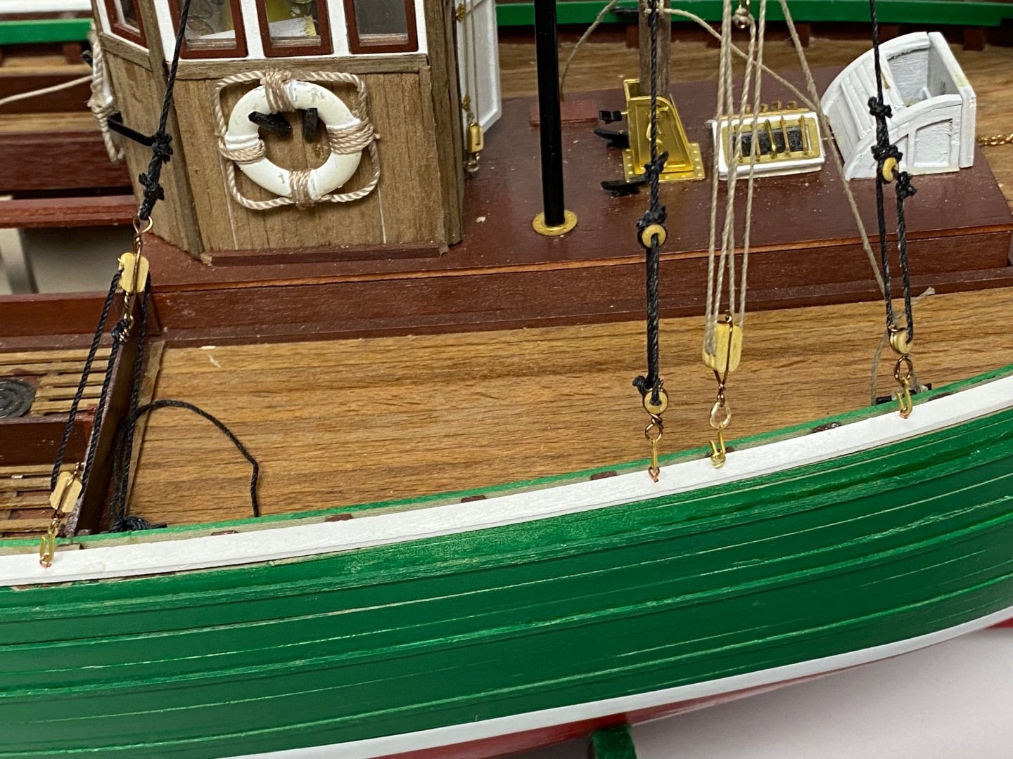
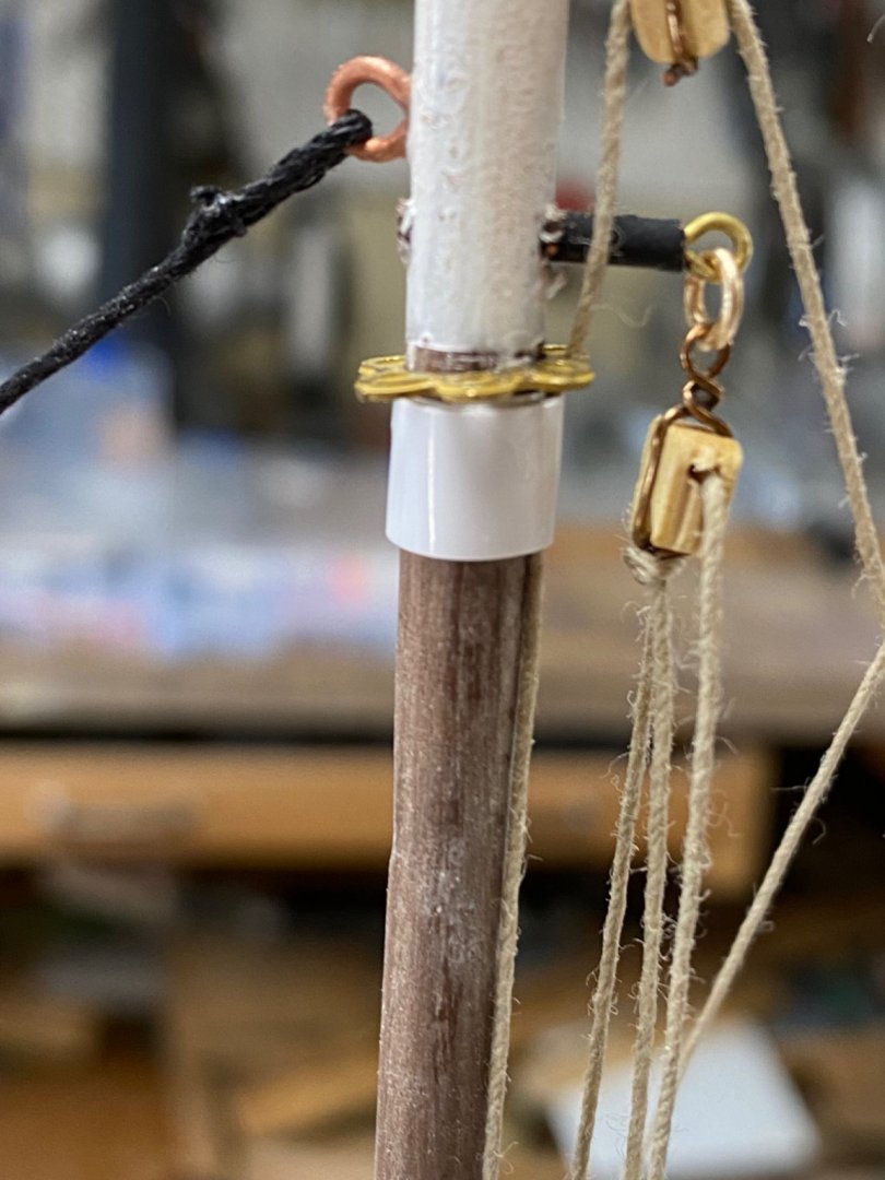
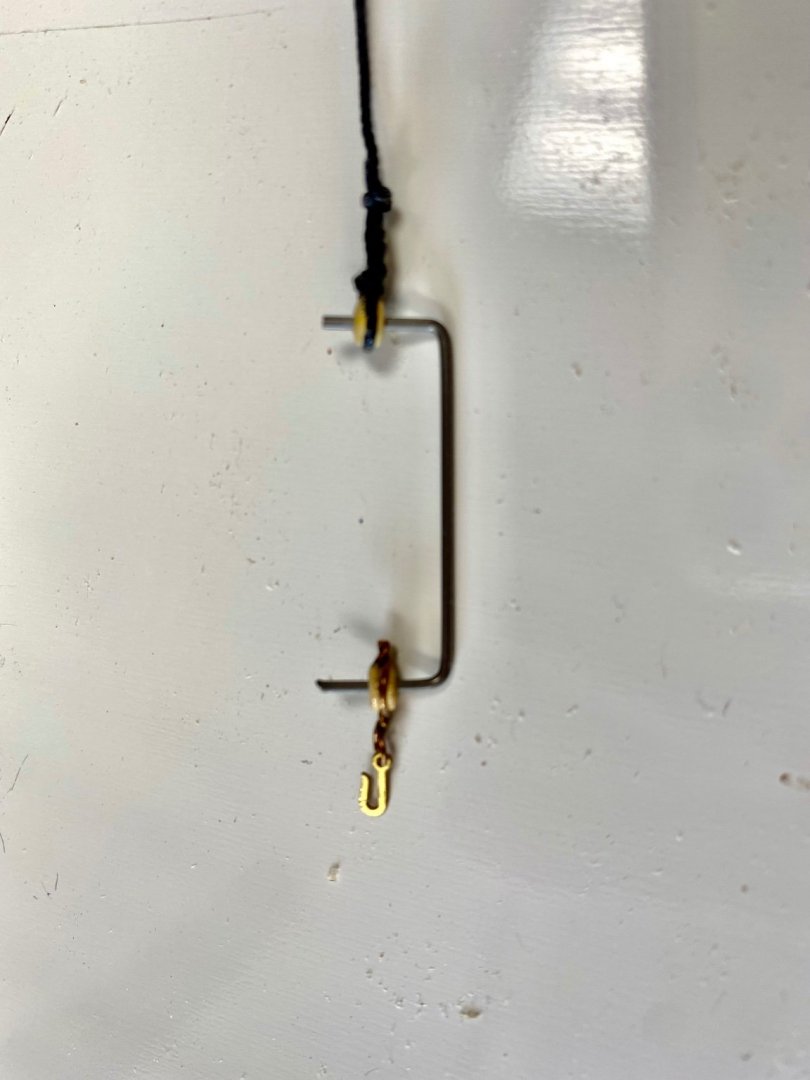
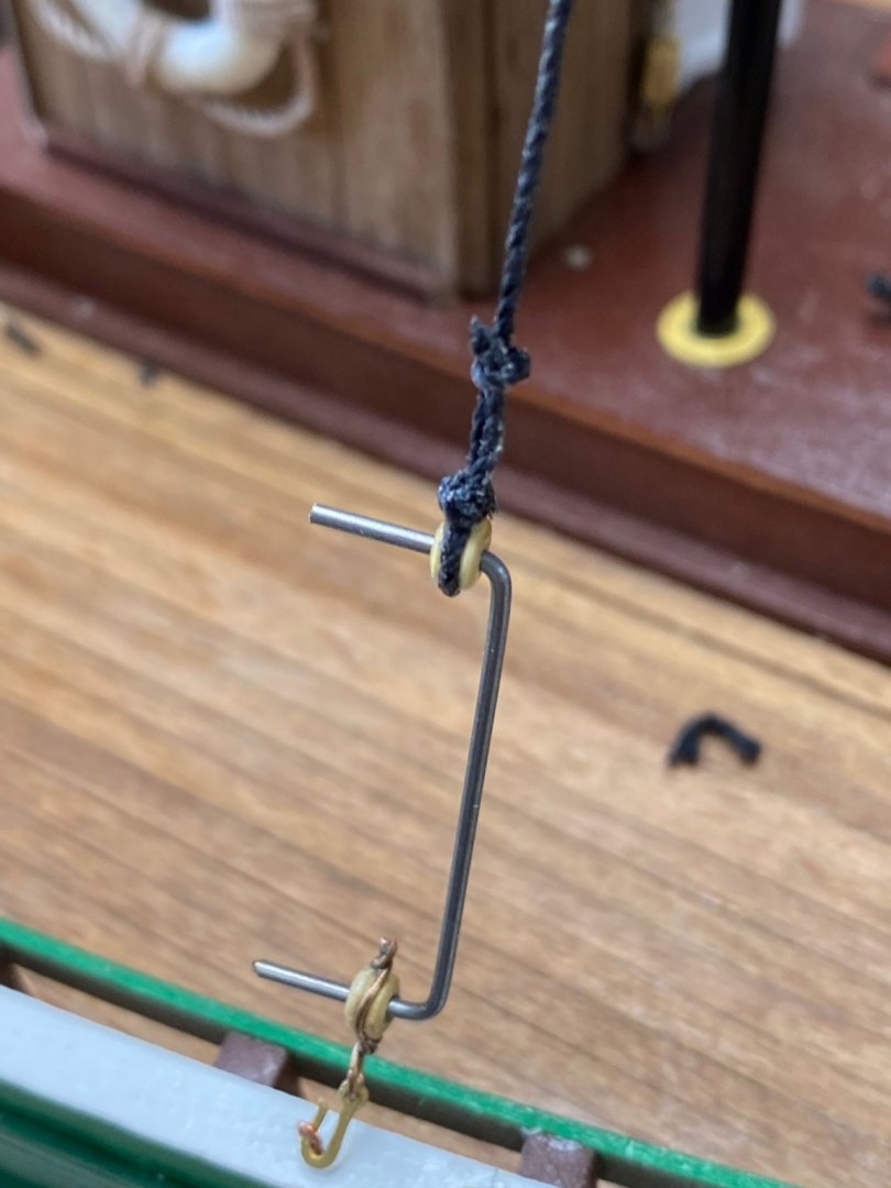
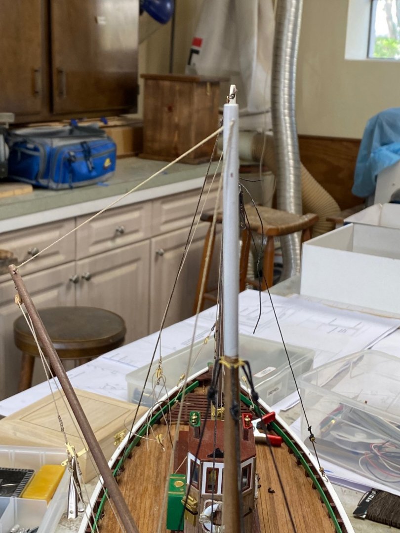
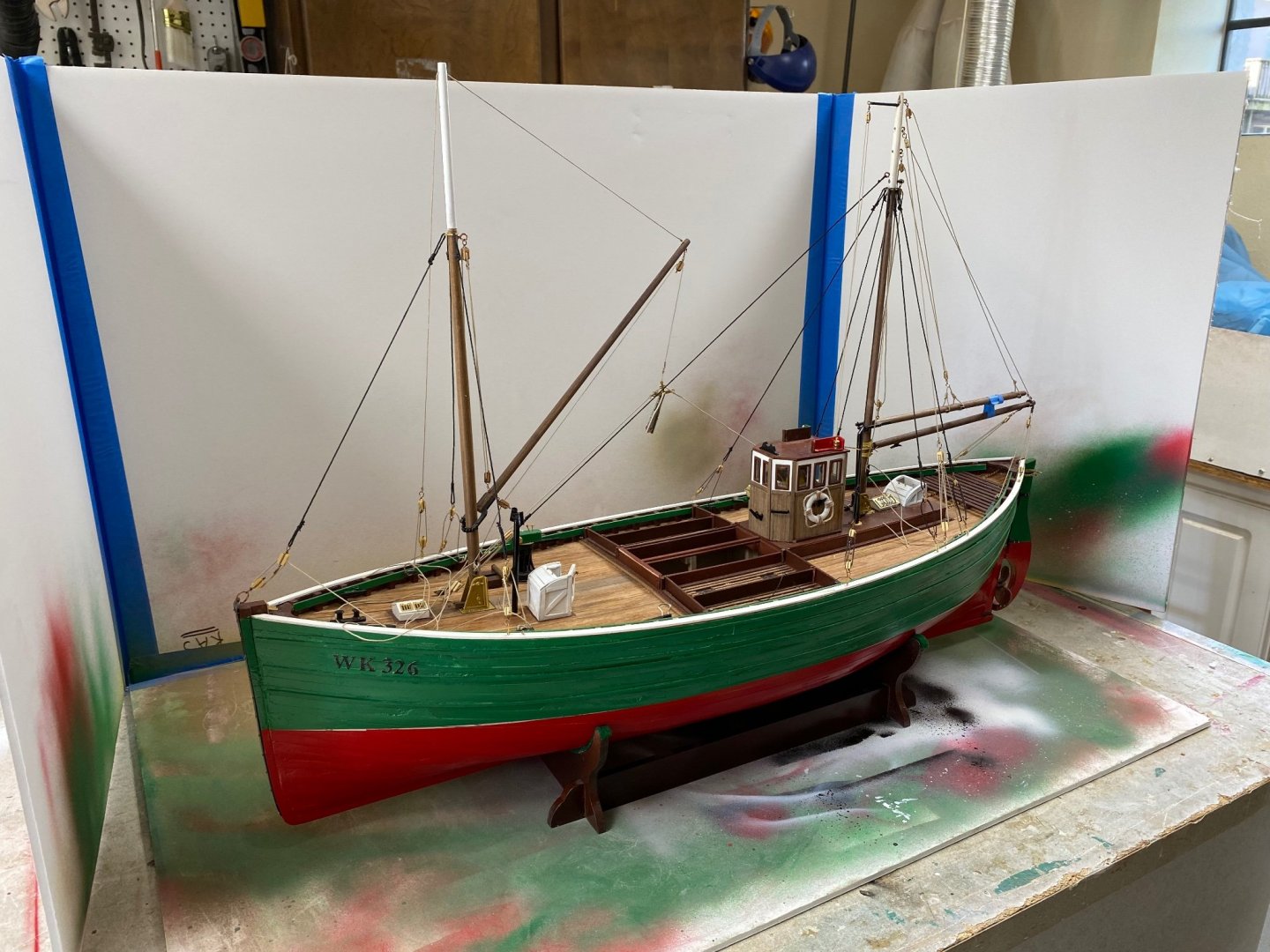
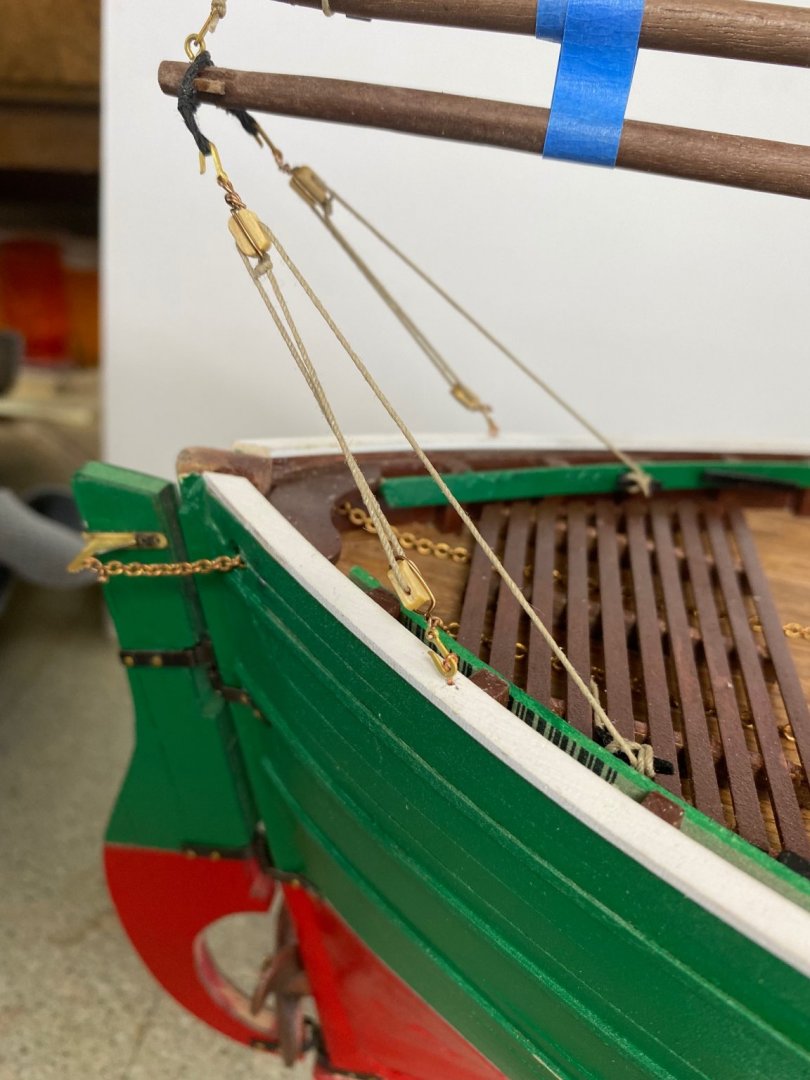
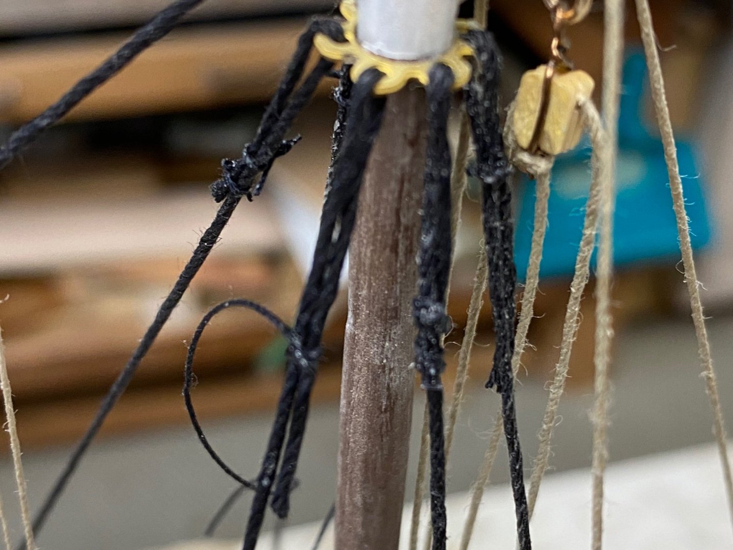
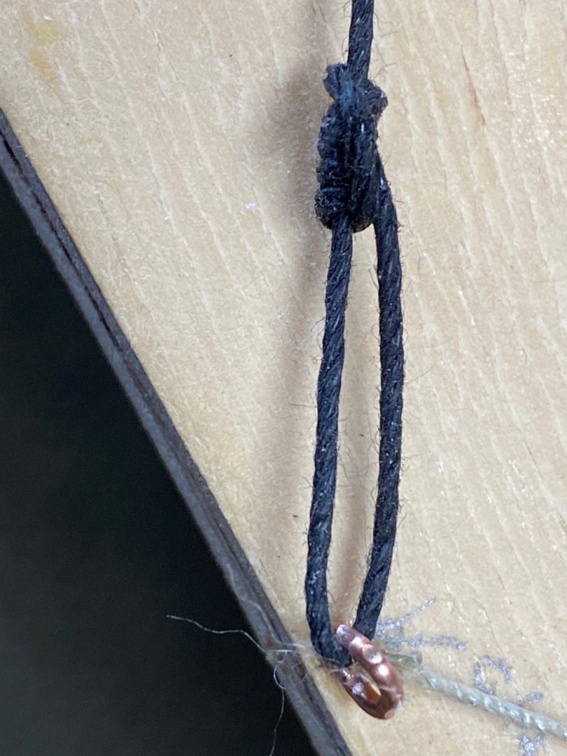
I had technically finished the rigging and while trying to set the sail I noticed that the aft mast was not standing straight. It was leaning slightly to port. Since the ship rigged I figured on tightening the stays of starboard and loosen the ones on port. After a little pulling, tragedy befell. The ring on the mast broke loose. My tapering of the mast was not very accurate and the ring found a way down dropping the stays with it. By then I decided to redo the whole aft stay system. First, I repositioned the ring and crated a ledge using chart tape. Then I proceeded to re-fabricate the stays. In redoing the bullseye's stropping, I used a simpler method with just an overhand knot and CA to retain the line to the spool. I built a music wire jig to hold the bullseyes at the proper distance. Then I inserted the stay in the ring and, still using the jig, installed the bullseyes in the rail. I, then proceeded to run a single line between the bullseyes closing the loop using an overhand sliding knot to tighten the rig. Repeated the procedure on the opposite stay and plumbed the mast. A photo of the stay will follow. After installing both port and starboard stays the mast straighten, as you may see on the photo taken from the bow. I am pleased. Next, I will complete the installation of the rest of the stays ( 4 count).
-
Ives, I am sorry I missed you name in my previous reply. Another senior moment. My comments above also include you. Thanks
-
Roger, Veszett and Valerliy, I really appreciate of your suggestions. As soon as I read your replies I opened into a second window to look at Roger's work on the Benjamin Noble. I will probably do the wood planking of my the model in the classic way since I feel that double planking will increase the girth of the ship out of scale. Then I will develop the plating as describes by Roger since Amapá is already started as a half hull. For the actual plates I tend to like Valerliy's idea of the shellacked paper. I will have to do a a little sampling before proceeding as I have never shellacked paper. Thanks a lot again guys, you got my head whirling right now.
-
Thanks Allan. I will look for PMing Greg.
-
I have a question for the forum. This model is going to be wood planked over bulkheads. But the ship was iron and I would like to hear from you regarding how to make planked wood look like metal. I have seen a few ideas such as copper or aluminum foil and cannot visualize a smooth finish. My thinking was something in the line of papier-maché ; using tissue paper and airplane model dope. Other modelers I have seen covered the model with a ladies hose fabric , epoxied it over and sanded. Your comments and/or ideas will be most appreciated. Construction continues on Amapá. I am currently cutting the frames. I will post pictures shortly. Thanks for looking.
-
Happy to see this post. I have been looking for 1/64 scale figures for my Amapá. I found some railroad figures at Michael's and I intend to convert them to Brazilian Navy seamen for my gunboat. Good to see another potential supplier of scale figures. I need one officer, a helmsman and maybe 2 seamen for the gun. I will follow this post.
-
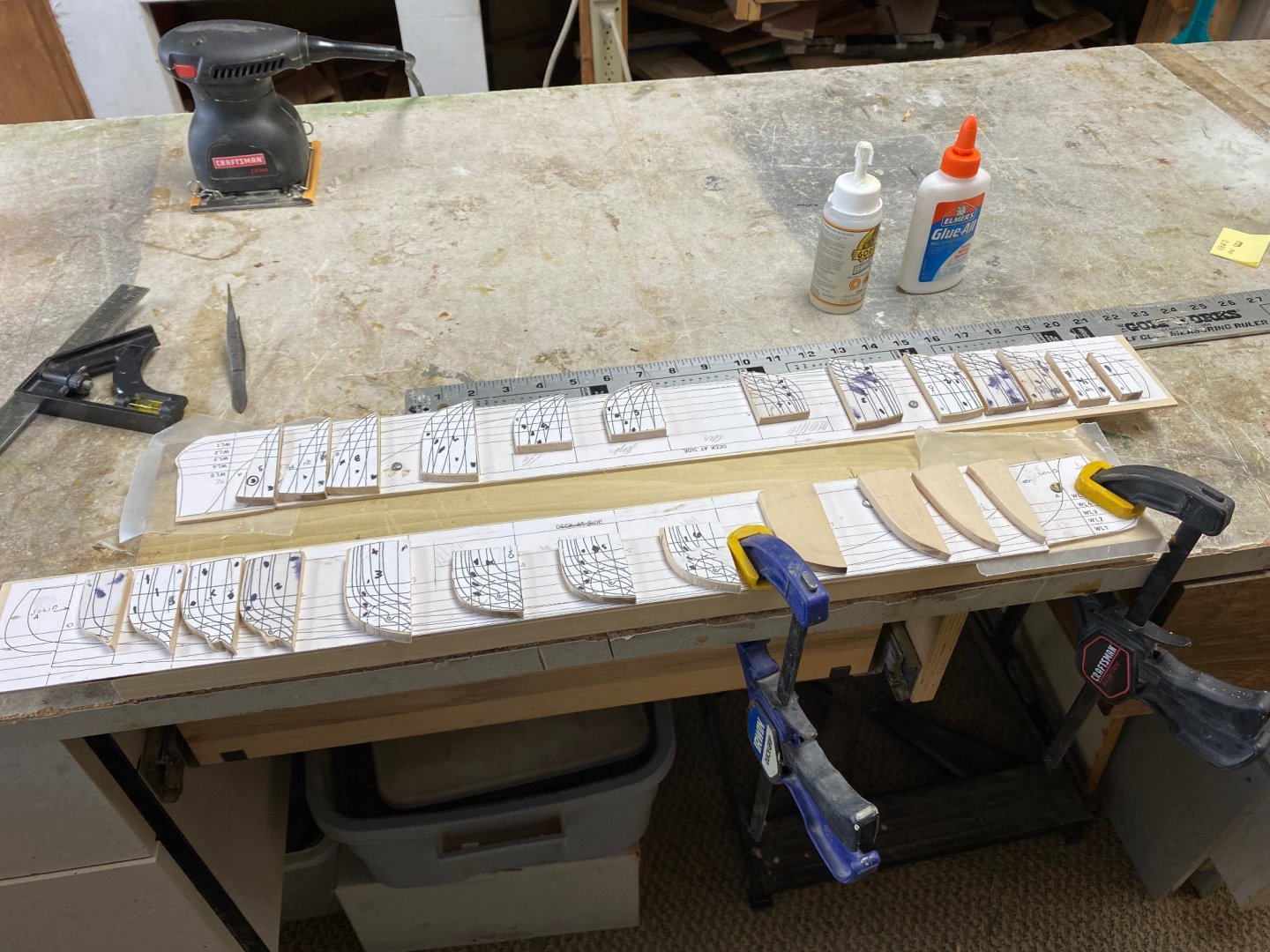
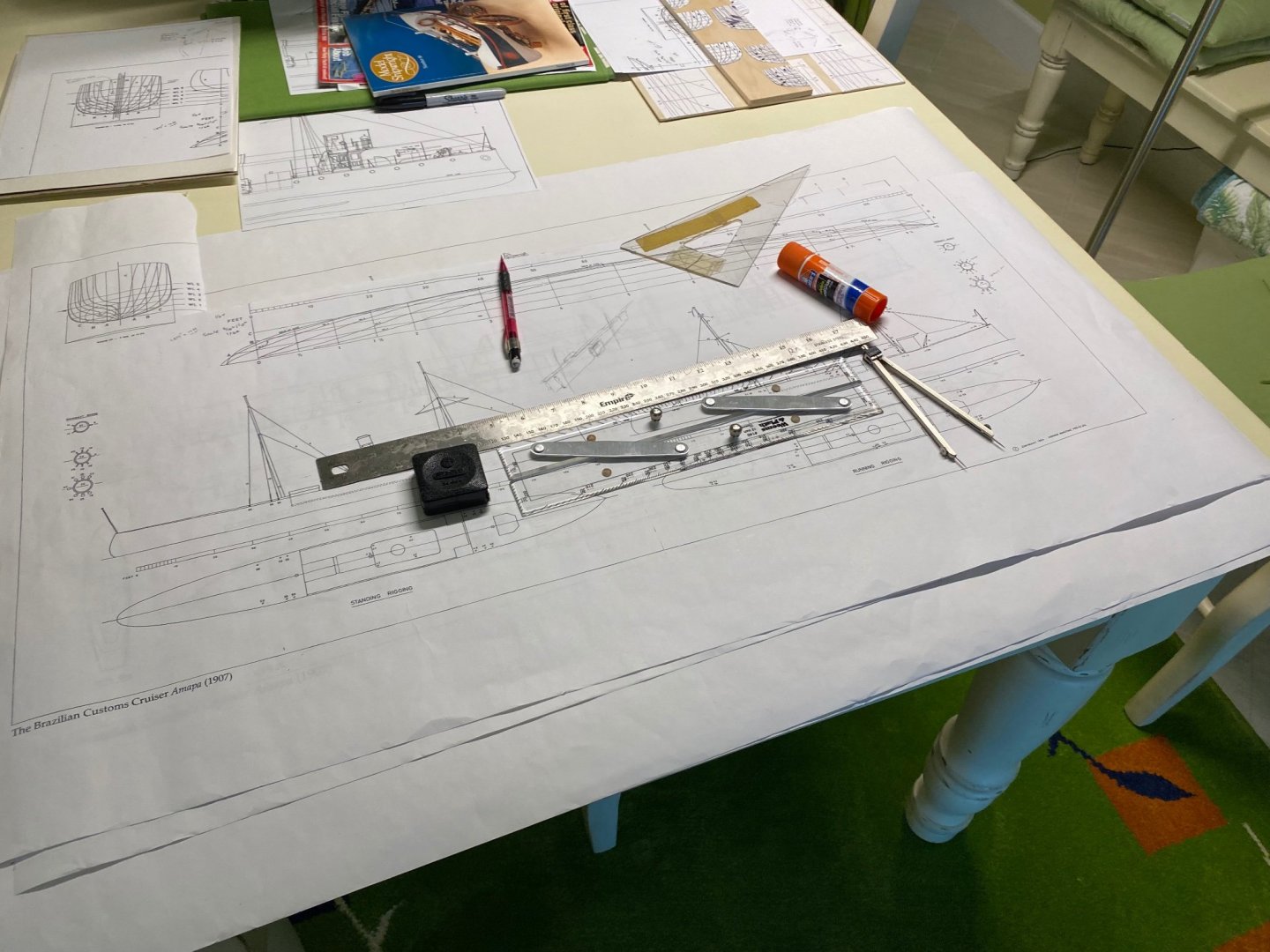
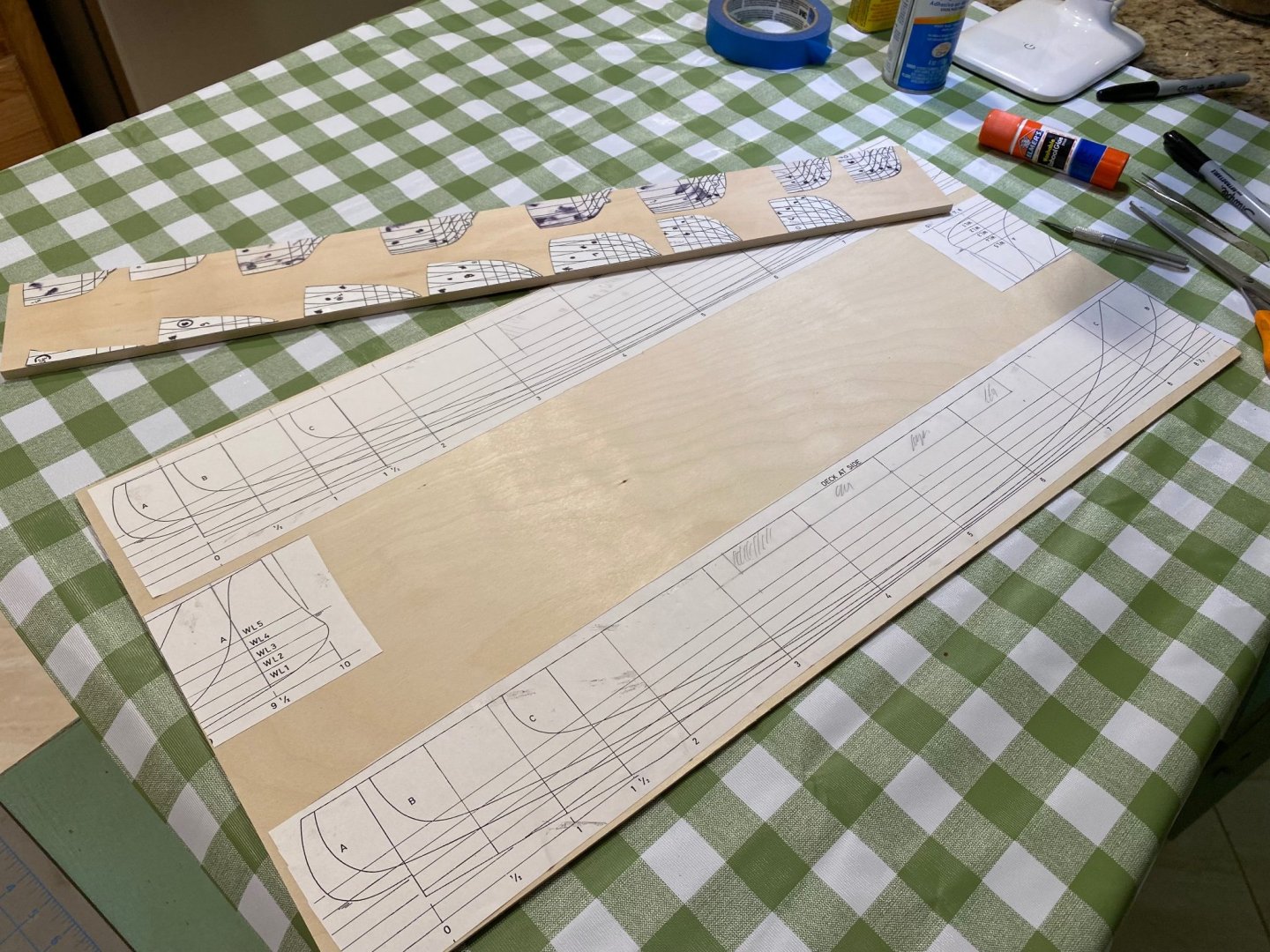
With my wife out of the country I have been using our dining table as a drafting board. She is coming home tonight and I must clear this mess before she comes. I have been busy working on both of my builds. Doing a little bit of detailing and touch up on the Fifie and starting the work on Amapá. Today I started the to fabricate the ship's frame. As I stated before, I intend to build the hull in two halves. I tried several glues to attach the drawing templates to the wood. After using the Elmers spray adhesive I had a disaster as the glue came on too thick. I finally decided to use regular Elmer's school glue that is a paste and will be removable from the wood after cutting. The keel section is 26" inches long and the available wood was only 24". I split the keel section by splitting the nose at station 9. I intend to use balsa fillers in the bow and in stern sections so this split may not be a problem. This is the finished board ready for the saw. This was done in our kitchen counter. Notice the oil tablecloth I use to keep anything messing up our counter. The Admiral will be happy ,LOL. Thanks for the support
-
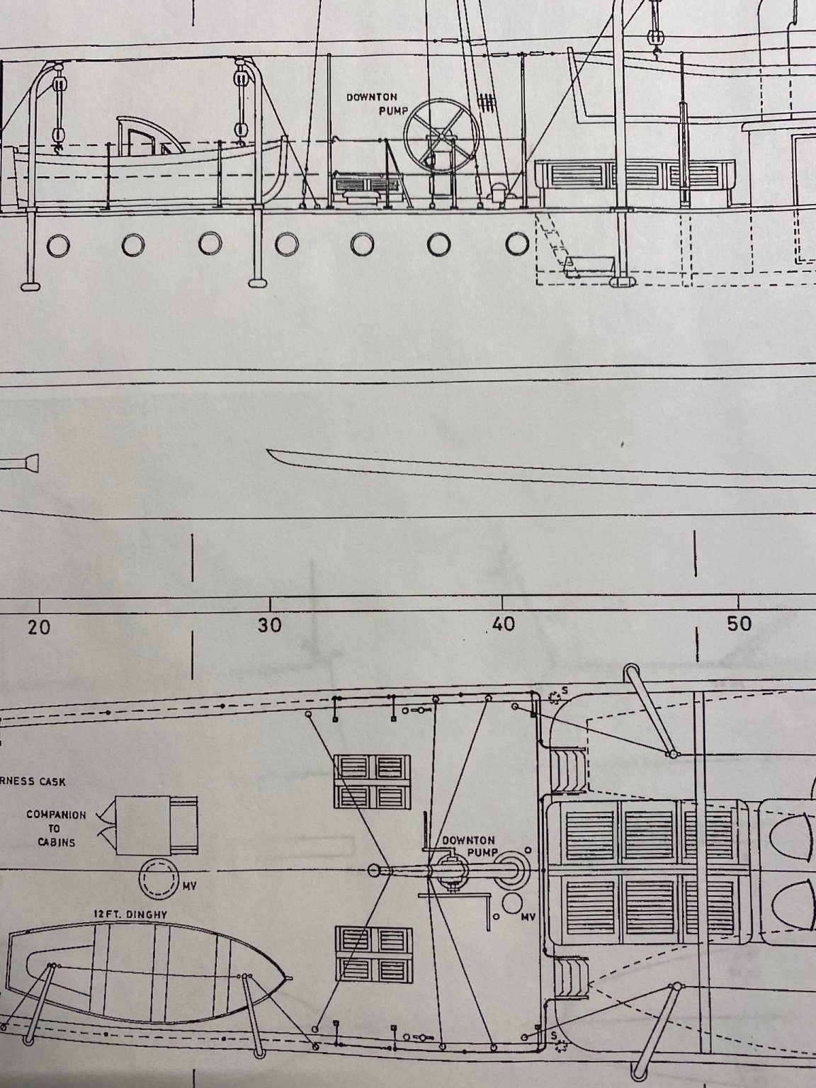
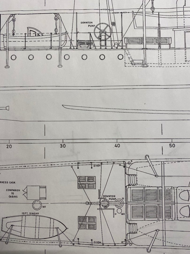
Valerly, thanks for the drawings. You are right. I used the information I found with Google but looking at Amapá's plans they show exactly a pump like your last two drawings of a downton pump. So I stand corrected and my model will use your plans. Thanks lot. This another reason to be part of this group. Here is a section of my plans and you see that it looks exactly like Varerly Thanks again to all of you or your comments and suggestions. Today I was working on the plans to start the frame fabrication.
-
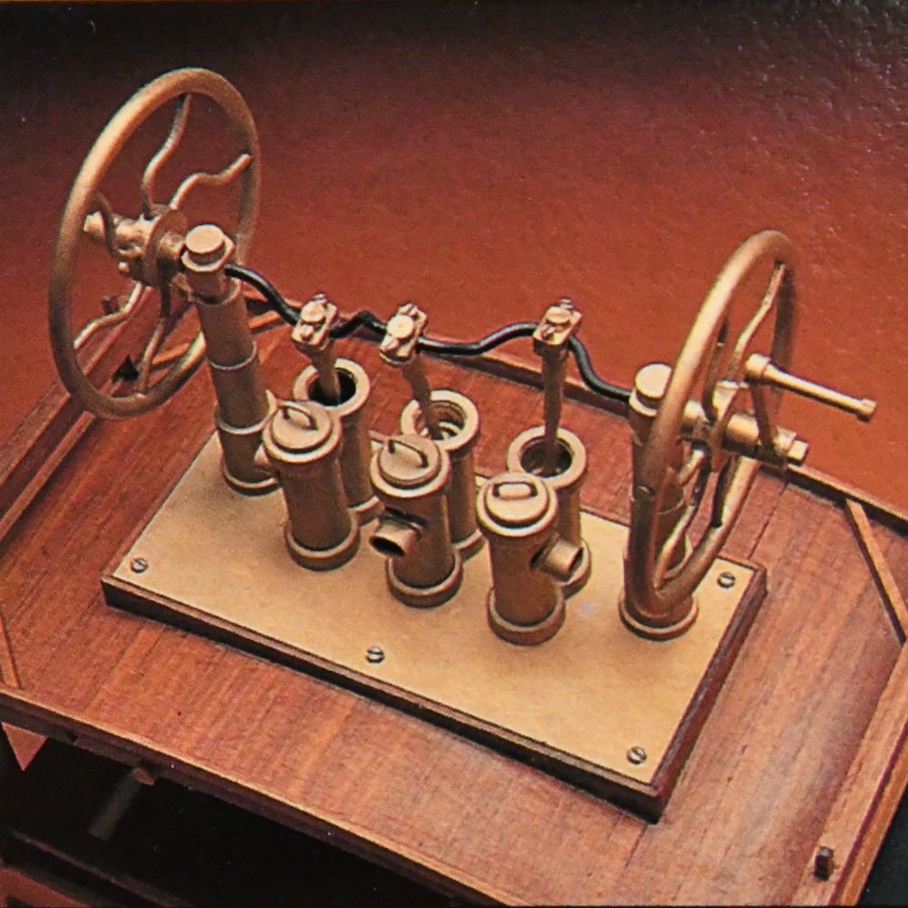
Thanks to all of you calling my attention to the forum section for this build. My bad. I really intended to do that but slipped. Much thanks to Chris for correcting it. Today I purchased the material to start making the frames and did research on the bilge pump. Google actually directed me to MSW to a build from GAW on July 27, 2015 and from Mantua models. This is how a downton bilge pump looks like: The model is of a three spout bilge pump which was a standard part of the fast clippers of the English Merchant Navy and thus probably used by Thornycroft on this ship. The model is of a three spout bilge pump which was a standard part of equipment on the fast clippers of the English Merchant Navy.
-
Thanks for posting this. I am an engineer (retired) and often wondered at how they did the dredging in the 18th and 19th century. Now I see it. The book's price though is pretty steep but again thanks for information
-
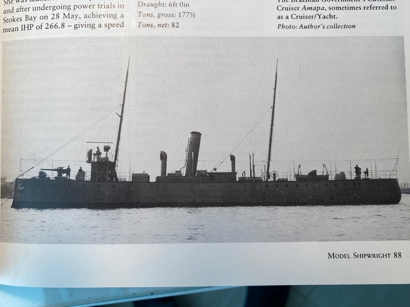
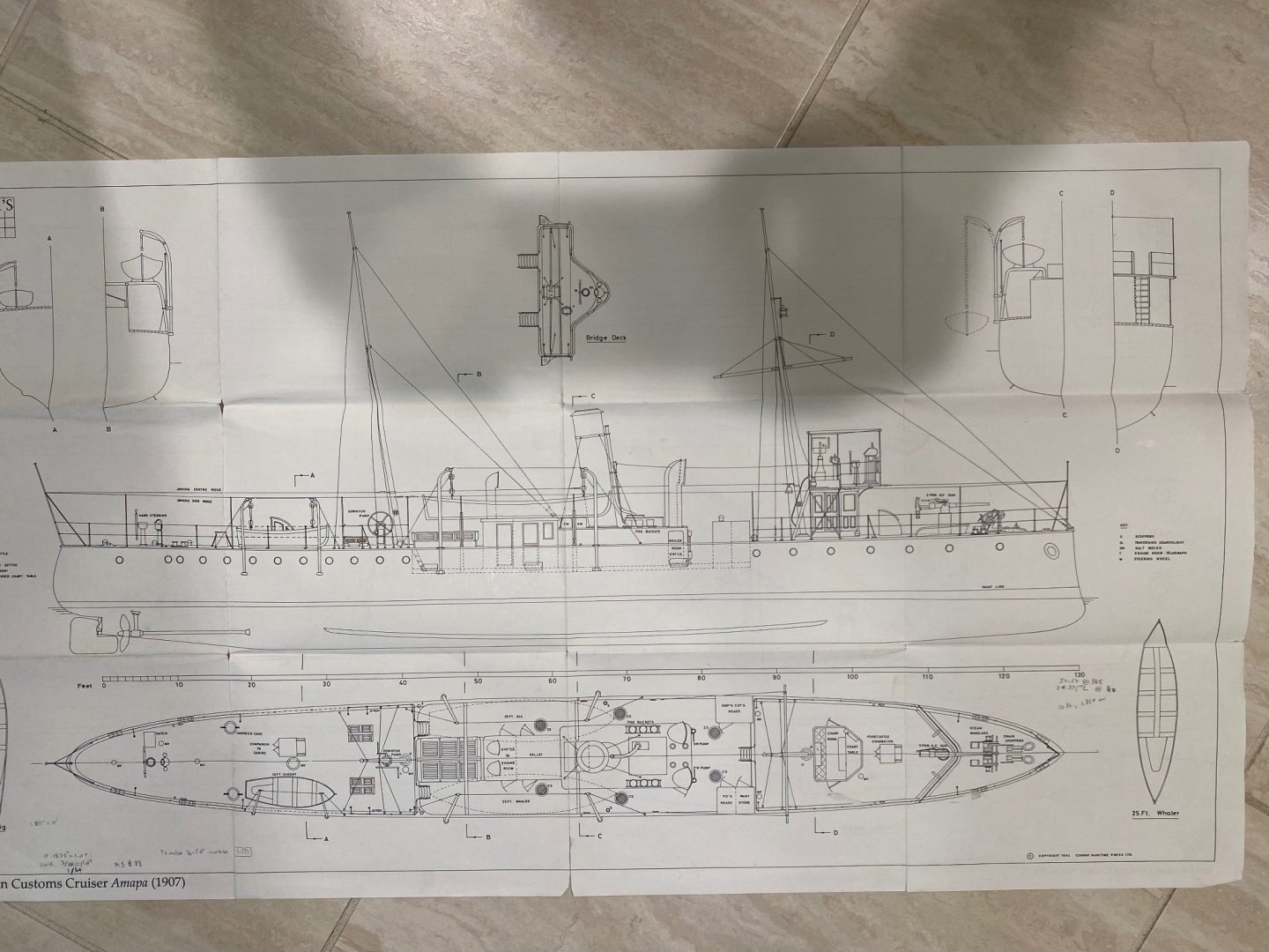
One of my favorite eras of the ship building industry was the period at the end of 19th century and beginning of the 21st. During that period the navies of the world transitioned from sail to steam power and from wood to metal construction. The ironclads were born. In my modeling career I always wanted to build a Dreadnaught but found that in order to build a reasonable size “house” model it will have to be a small scale. The plastic industry produced a lot of kits with extraordinary detail but I wanted to scratch built one and my abilities were way under those of some of our modelers like Valeriy V and Wefalk. I lived in the Hague for a while and, while there, I subscribed to the Model Shipwright Magazine. They provided a plan and a brief description of a selected ship in every issue. I saved these plans for the day when I had enough time to devote to my hobby. The plans for this build show what I may call a miniature dreadnaught. Steam and sail powered, 130 ft length and at a scale 1/64 which will allow plenty details including a single, deck mounted, QF gun. The ship is the Brazilian Custom Cruiser Amapá that was laid down in 1906 as Yard No. 459 at Thornycroft’s Woolston (Southampton) yard. She was launched on 30 April 1907and issued to the Brazilian customs authorities on June 4, 1907. No further information is known about this vessel except that at some stage she was renamed Oyapock and she remained in service until 1918. This information is from the Model Shipwright magazine issue No, 88 The photo shows Amapá during her service with the Brazilian navy. Amapá was named after the region in the north of Brazil next to the Amazon. The ships dimensions are as follows: Length between perpendiculars: 130’0” Length overall: 137’0” Beam: 17’0” Draft: 6’0” Tons, gross: 177.5 Power: twin triple expansion steam engines Sails: Two masts with a stay sail and try sail Armament: One 3 pounder QF gun This will be a simple ship model in 1/64 scale with plenty of detail. My plan is to build the hull in two halves and use a plank on bulkhead method. I will scratch build most of the model but will still use available manufactured fittings. I have been studying these plans for quite some time and will be ready to start cutting wood shortly after I finished my current build: Amati’s Fifie I want to thank the members of this forum which have provided me with valuable information. They always said that is never to late for an horse to learn new tricks. Your comments have improve my craftsmanship as a modeler. Thanks. Ras Current build: Scottish Motor Fifie. 1/32 scale. Amati kit Previous builds: Patricia. Steam powered R/C launch. 1/12 scale. Krick Kit. African Queen. Steam powered R/C launch. 1/24 scale. Billings kit. Emma C. Berry. Sailing fishing smack. 1/32 scale. Model Shipways kit.
-
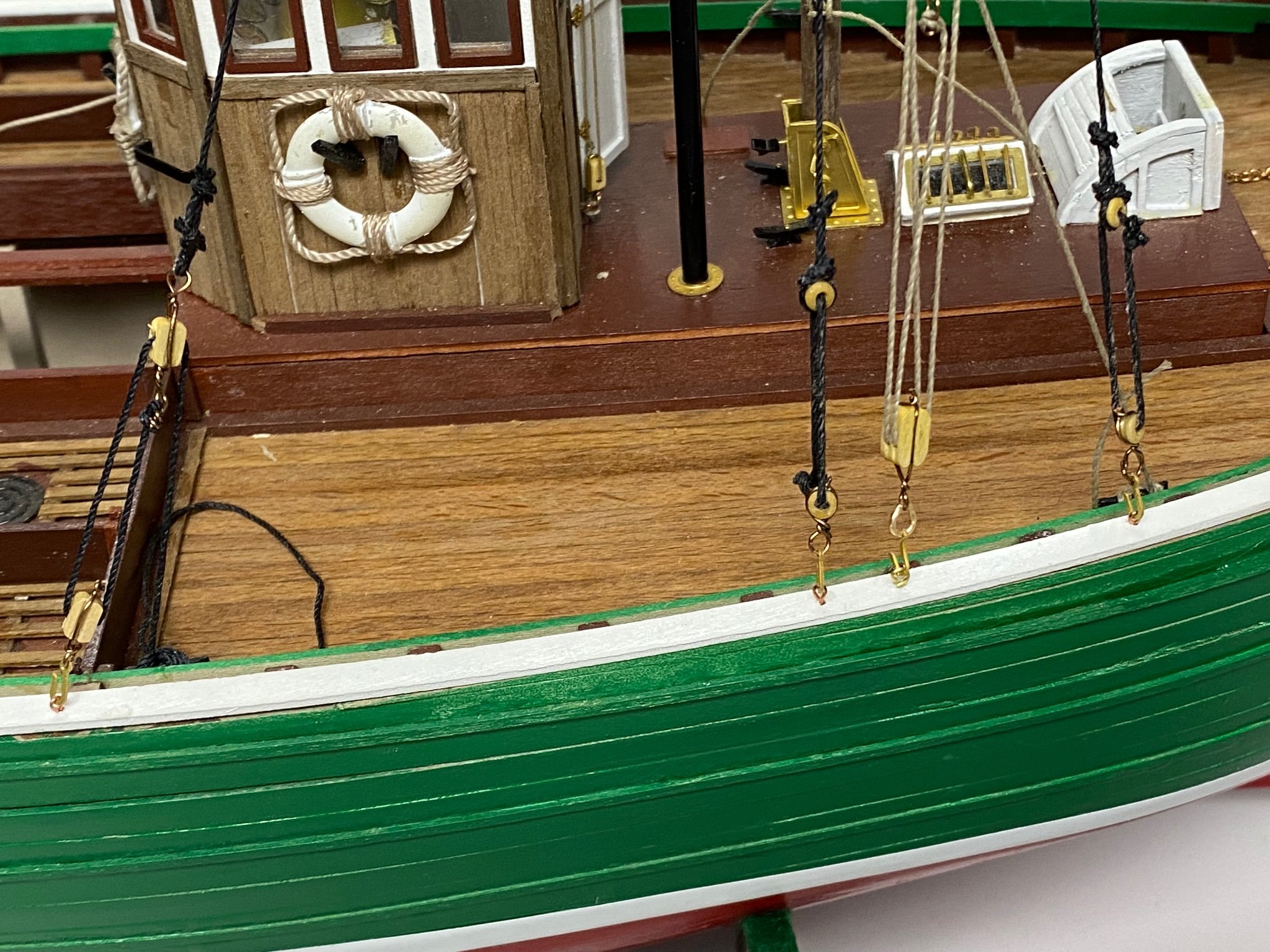
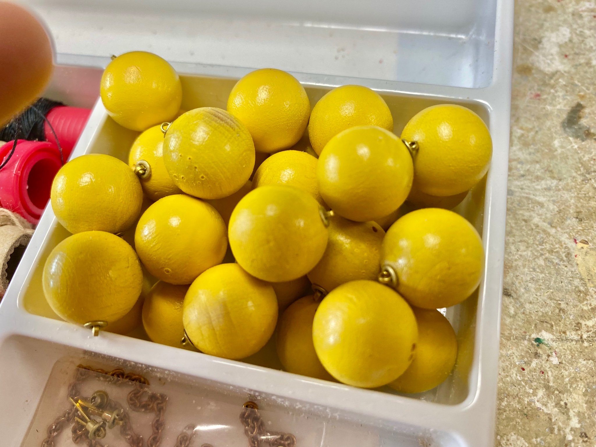
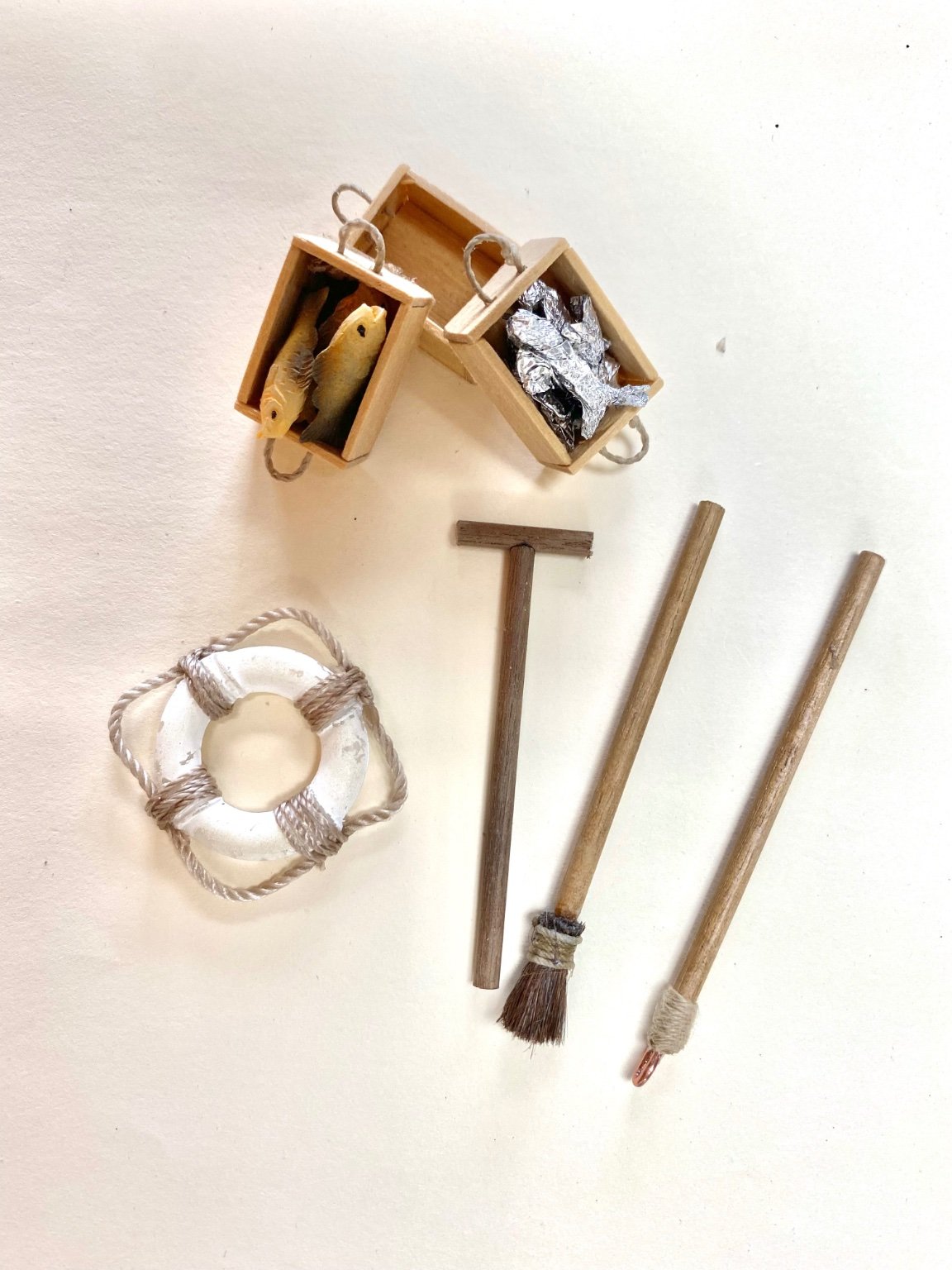
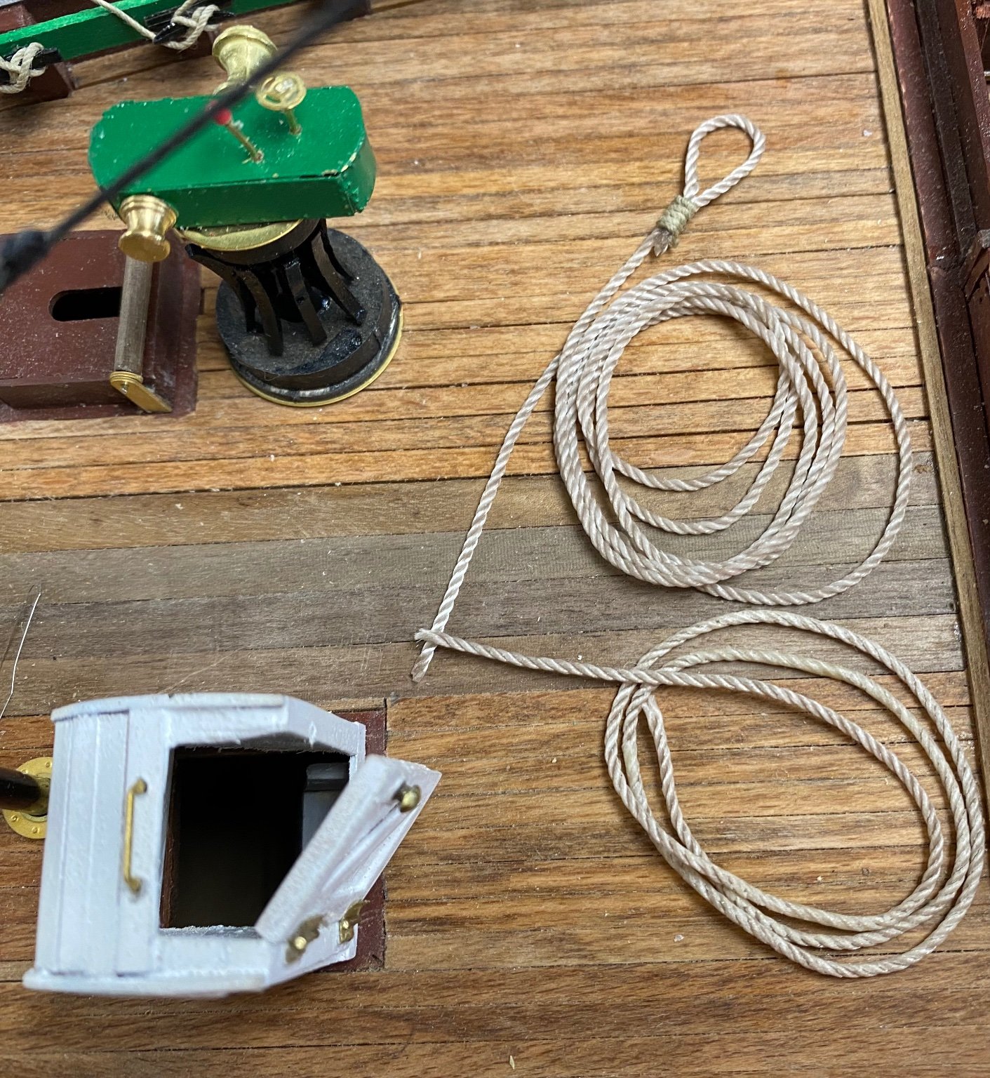
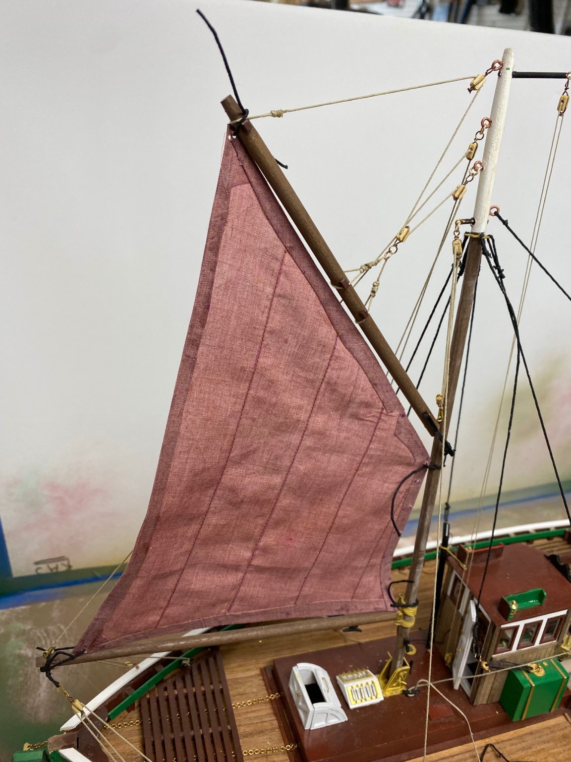
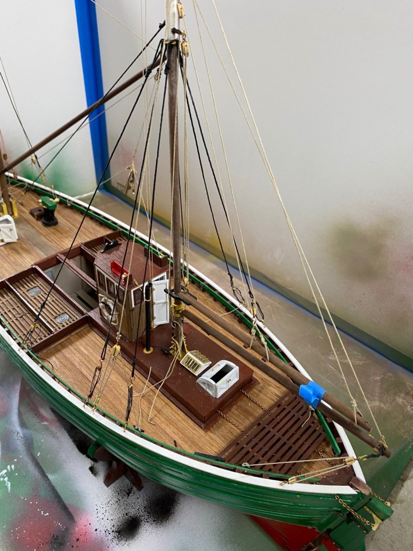
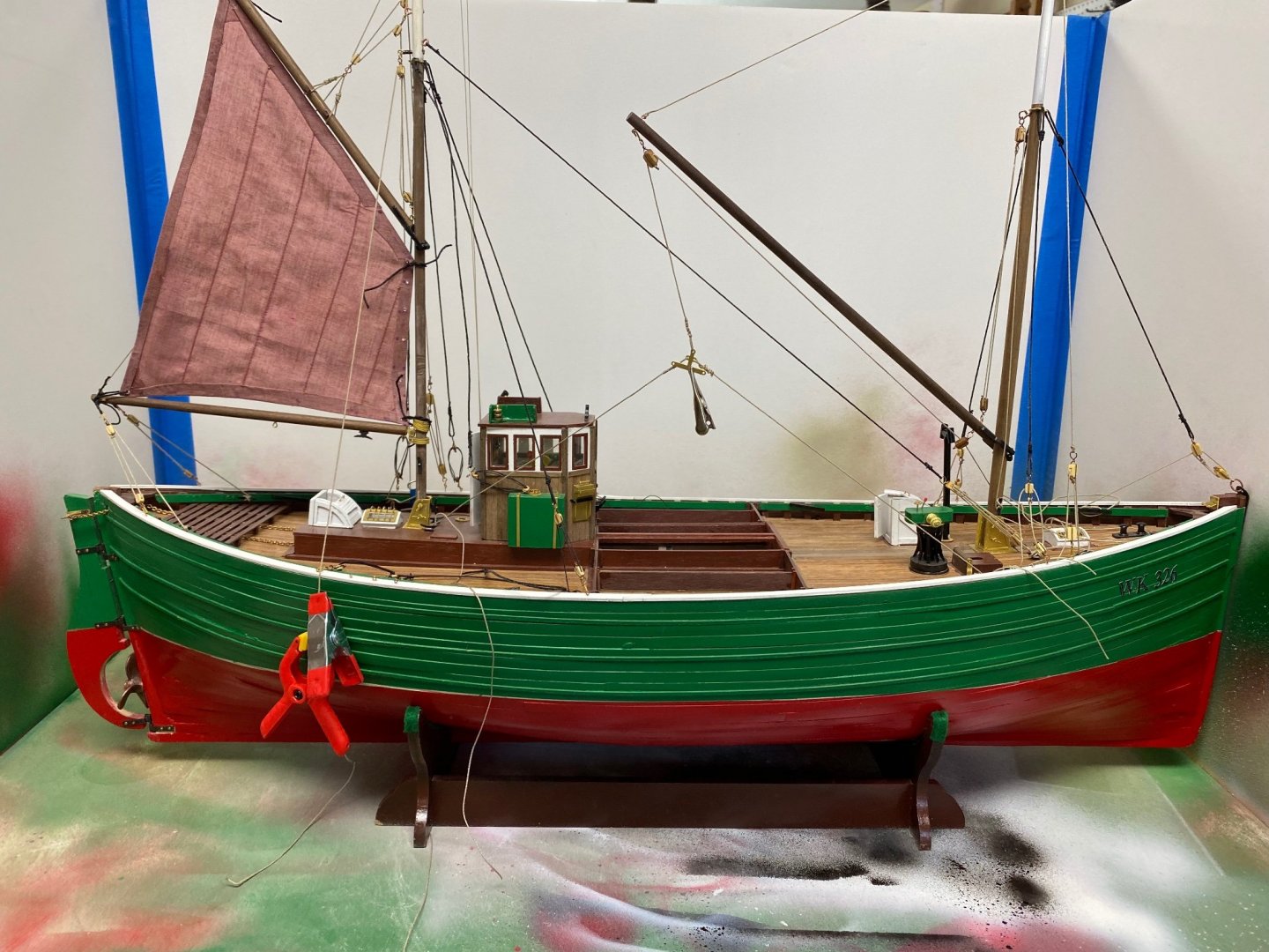
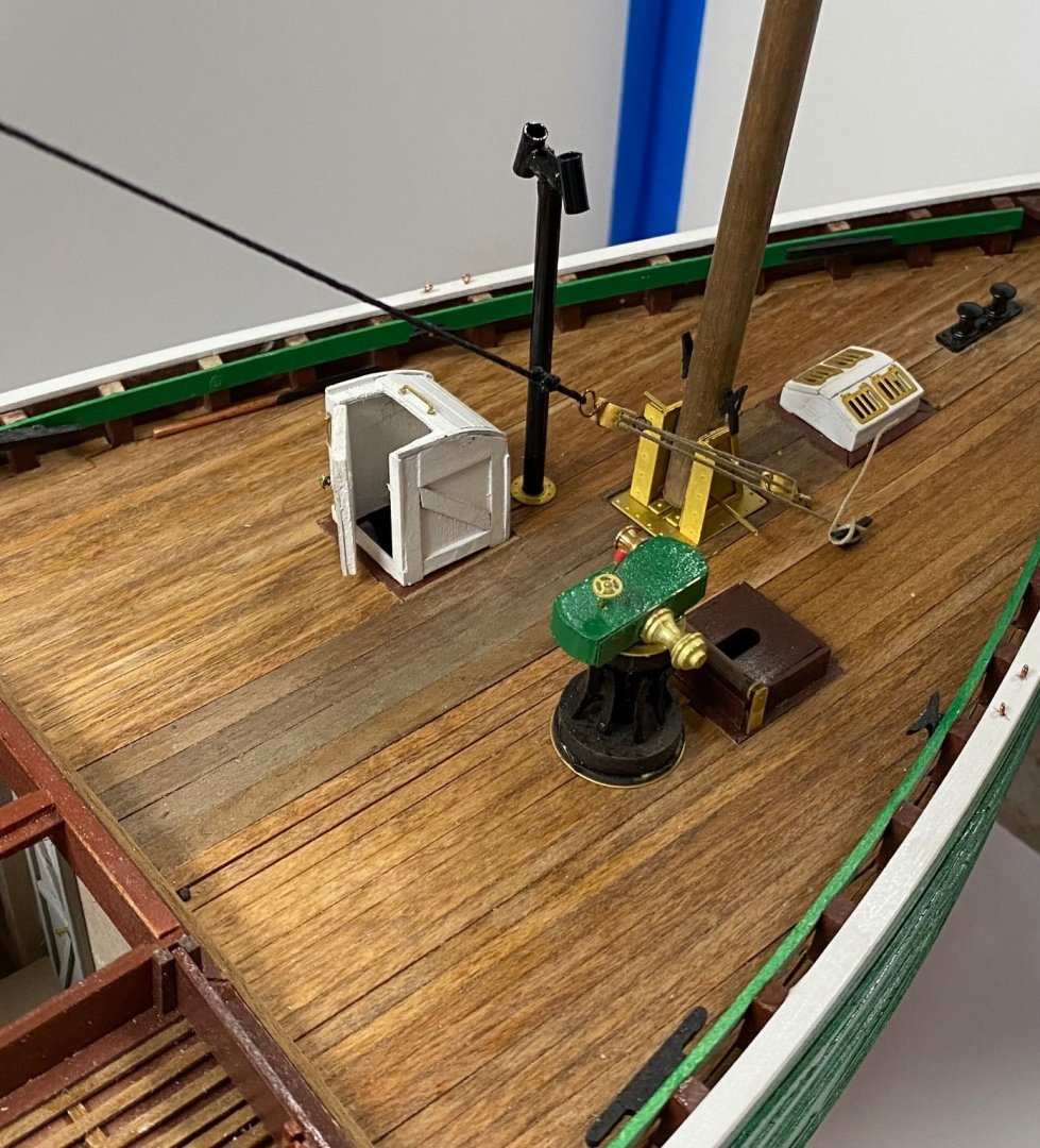
Thanks to all my watchers. Today I took a break in the rigging and spent the morning working on the deck small details. First, I completed the net buoys which had previously painted. Following are some of the details I did today plus the boxes and fish I had previously built. My basic idea is to present the model as ready to dock and start the unloading of the catch in the quay. The herring fishing was done using long drift "gill nets", hence, the boats were named: drifters. The fact was that the net caught all the fish around the school and, in the cold water of the North sea, that included cod and bluefish. My research indicated that the crew actually separated these fish from the herring and either sold them separately or took them home for mama to cook. I found the nicest fish at Michael's and they are almost to scale. So here are my deck implements: I am really proud of my mop. Tried to make it the way the booklet explained but the results were not satisfactory. Today I had an epiphany. I saw one my paint brushes and found my mop. It was easier that it looked. The bristles of the brush are clamped together with the metal bushing. I used my needle nose pliers to loosen the grip on the bristles and then tied a knot and served it. A little CA glue and I had the head of the mop. Also prepared some of the mooring lines to be stored on deck. I have been testing soaking the line in diluted Elmer's glue to see if the coils stay together. With my idea of the presentation after the catch, I decided to furled the sail.


-
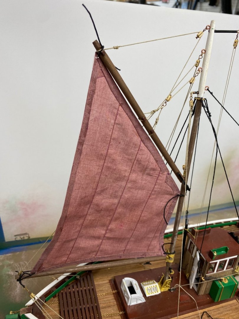
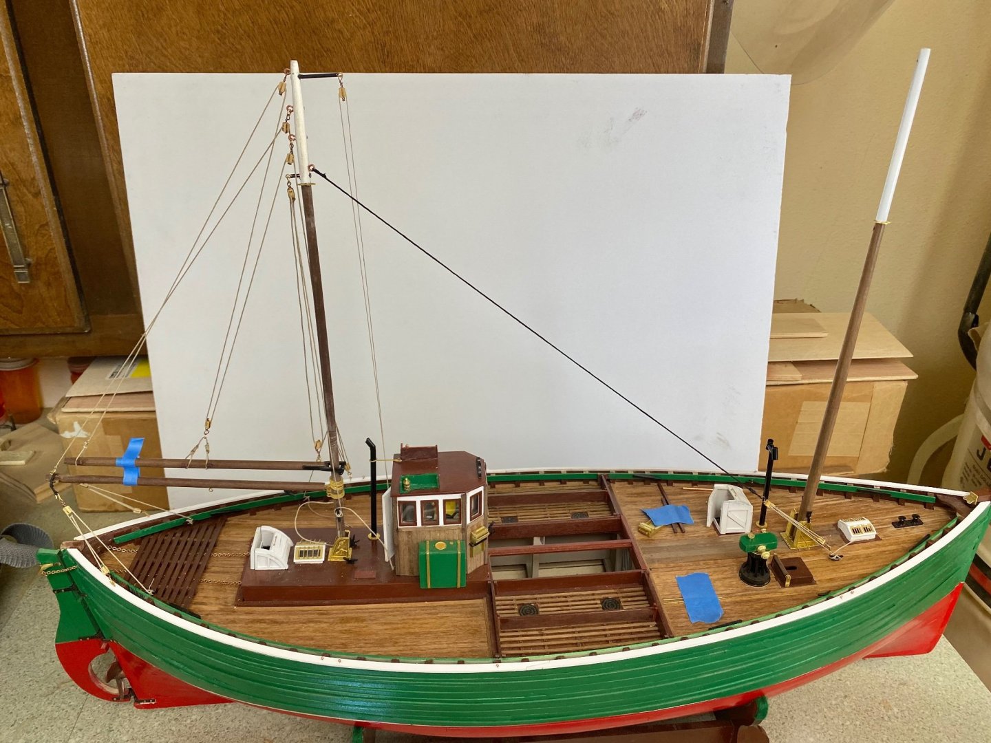
I am including some pictures of the rigging and the dry fitted sail. Little work still remains since I broke one of the stays while installing the sail. On my next boat I will definitely do the whole rigging including the sail in a scale mockup away from the model. On this one, I had trouble with the final length of the stays and, in retrospect, I would have done the gaff halyard a little different. Notice the slack in the aft mast stays. Thanks for looking. Ras


-
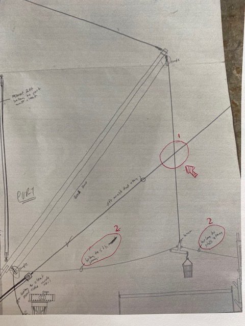
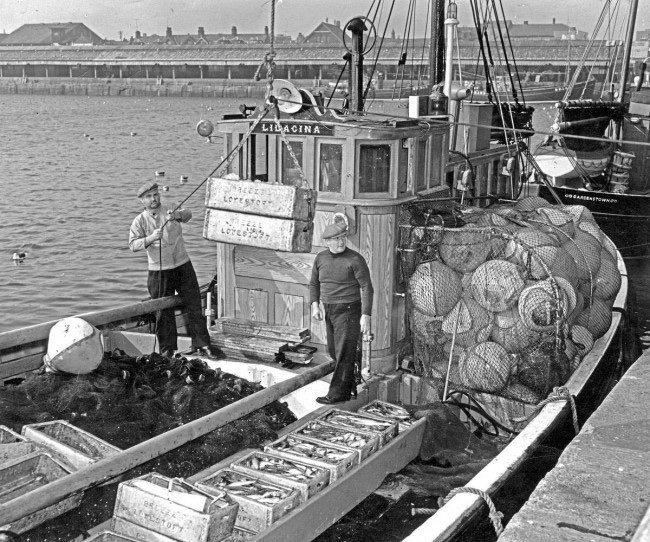
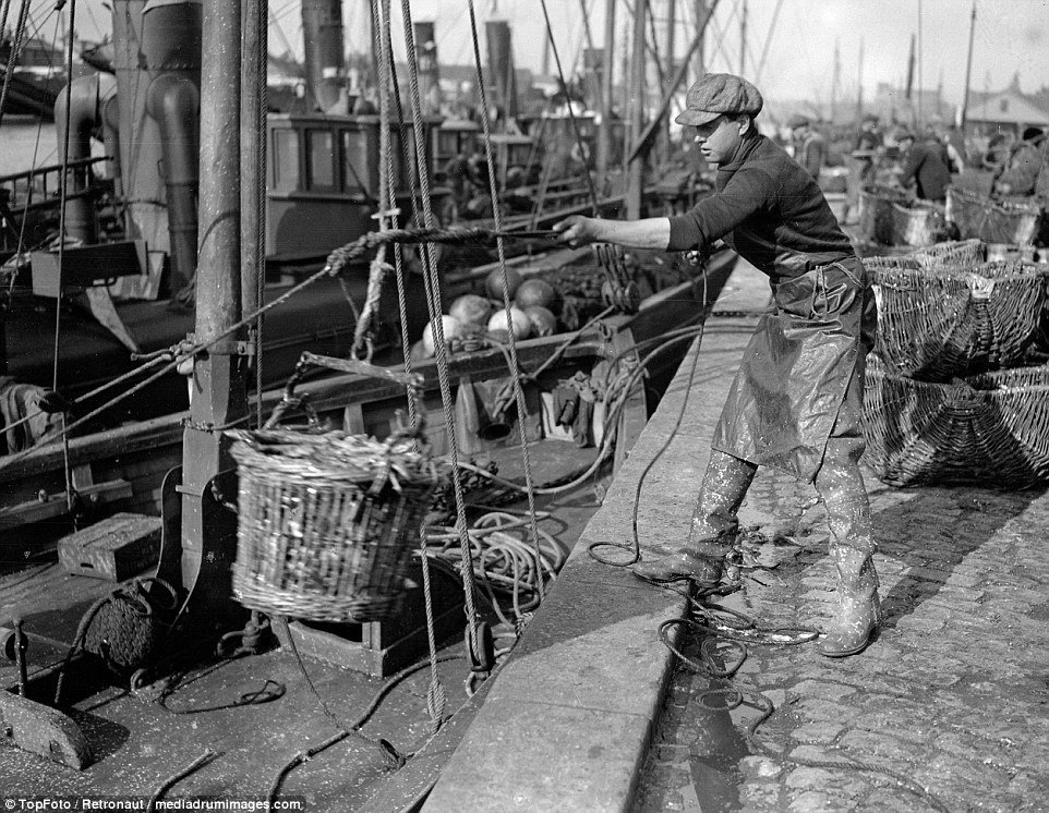
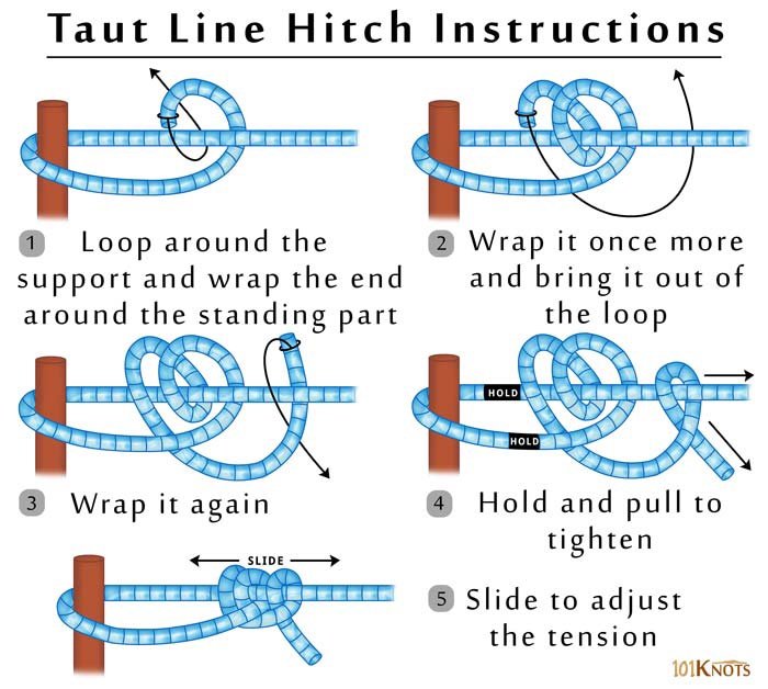
Today I have, technically, finished the rigging on the Fifie. Next will be to complete all the loose deck details. During this rigging I had trouble with the mast stays as it became very difficult to balance port and starboard to keep a plumb mast. As a result some of the tackle for my stays looks a little loose. I would appreciate any comments on the subject of controlling the stays tension to keep the plumb. MY method was a rolling knot but then the loops look unequal. Your advise will be appreciated. I also noted an interference between the after-mast forward stay and the load line for the derrick. The indicated arrangement in the drawing will only allow for loading from one side of the boat. This is shown on the drawing as item 1. The drawings are no very clear as to how to belay the control lines for the load, supposedly handled by the crew during the unloading. These are marked in the photo as item 2. Are they supposed to be tied to the stay? If so, what knot should be used? Following are photos of the actual unloading of the Fifie: Notice the messy decks. LOL
-
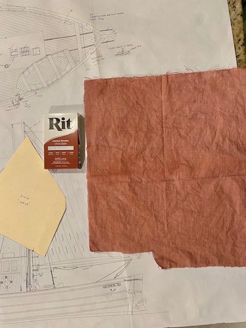
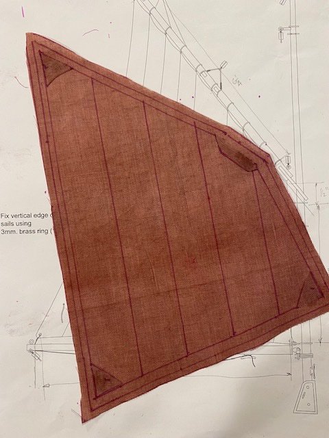
Thanks Yves. Today I worked on one of the stays in fwd mast. These ones are actually controlled with a regular block tackle but I wanted to check my idea of the sliding knot. I rigged the blocks and attached the one end of the stay, made a loop and served it in the bench. Then I run the other end through the mast ring and tied my sliding knot. Success. I didn't tighten it up completely because I need the opposite stay in place to keep the mast plumb. The only thing to watch, when tying this knot, is that the tightened loop be the size you want. I have dyed the sail cloth using the RIT Chocolate brown color. I made a template and cut the pattern and now all I need to do is to complete the hems and having my old lady friend stitch the panel lines. I am going to leave the stitching off the edge of the sail since I may consider furling the sail. Notice I added reinforcement at the sail corners

-
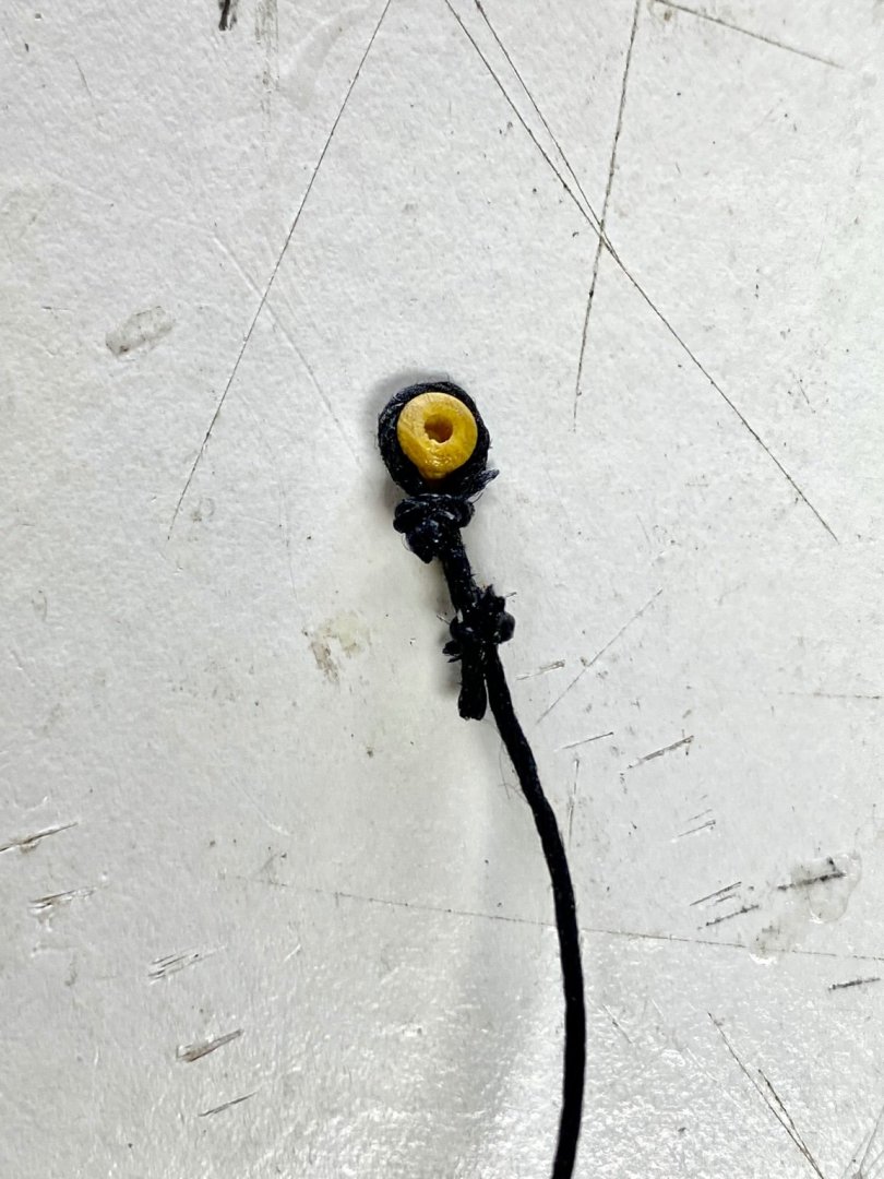
Almost finished the aft mast rigging After a little review of my work, I found that I could control the tension of the stays only in those stays with tackle. The ones rigged with eyes remained loose. I blamed it on the fact that they are looped to the mast to a brass ring and, when I tied the knots, I had no way to tension the stay. I also was having trouble trying to serve the loop. So I remembered my Boy Scout days and the sliding knot we used to tighten the tent stays. And this was the result It was easier to rig the stay on the bench and then place in the model. The lower part has a hook on an eyebolt on the rail and the upper loop went through the ring loop and then the knot was tied and tighten. Then, it dawn on me, that it would have been a lot easier to rig the whole stay in the bench and use a hook to connect the stay to the mast ring. Thats what you call afterthought. But I think I will revise all of the stay loops and replaced them with these knotted style.


-
Good luck cathead, everything looks fine from here. BTY, I think, when I do mine, I will keep the hull frame glued to the board. It will make the planking easier using the board as your third hand. Chris as said that it will be easier to remove the complete hull from the posting board later. My problem is going to be that I read this after I had glued the plans to my plywood working board. LOL