


Ras Ambrioso
-
Posts
661 -
Joined
-
Last visited
Content Type
Profiles
Forums
Gallery
Events
Posts posted by Ras Ambrioso
-
-
VTH, I am also following you. Once I finish Fifie I am going to do the NRG half hull to sharpen my planking knowledge. I love doing the small details and to improvise from common objects. This scales, 1/32 and 1/24, are perfect to make semi-real miniatures.If you want to see perfection, watch Wefalk. Happy having you as a follower.
-
-
Last night I spent a couple of hours following Wefalk's (Everhard?) build. He is scratch building the SMS Wespe, Imperial Navy armored cruiser (1876) in N scale (1/160). Amazing craftsmanship where 1 mm is a large dimension. He is fabricating every fitting and part of this boat using watchmakers tools. I learned a lot about preparation and the perseverance required. .
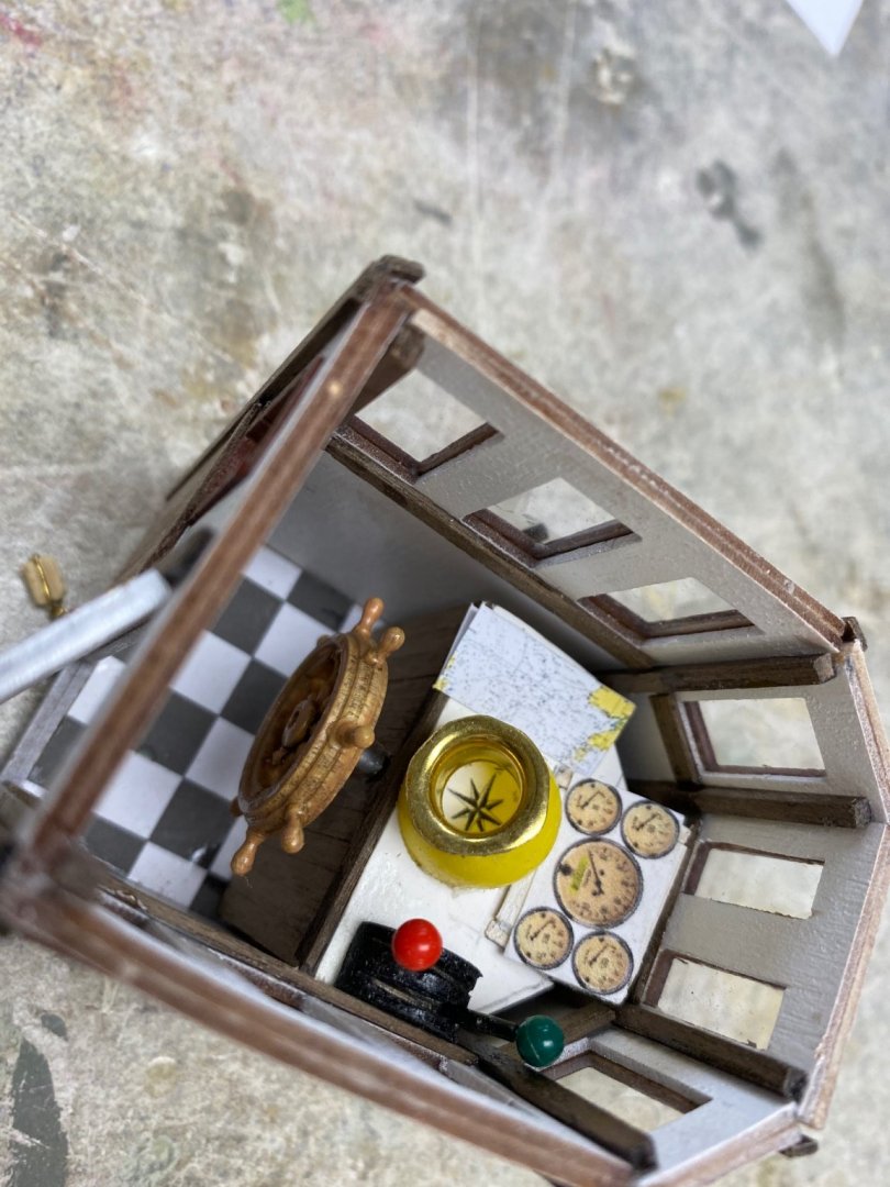
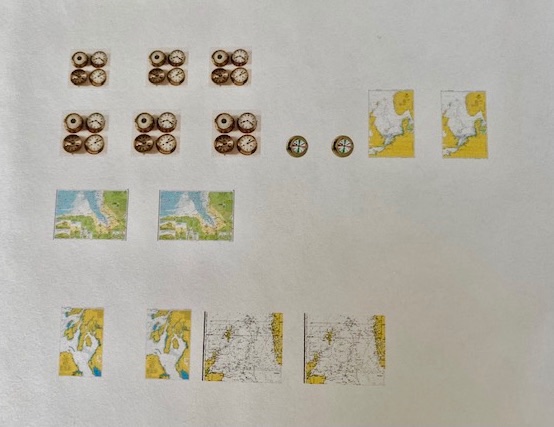
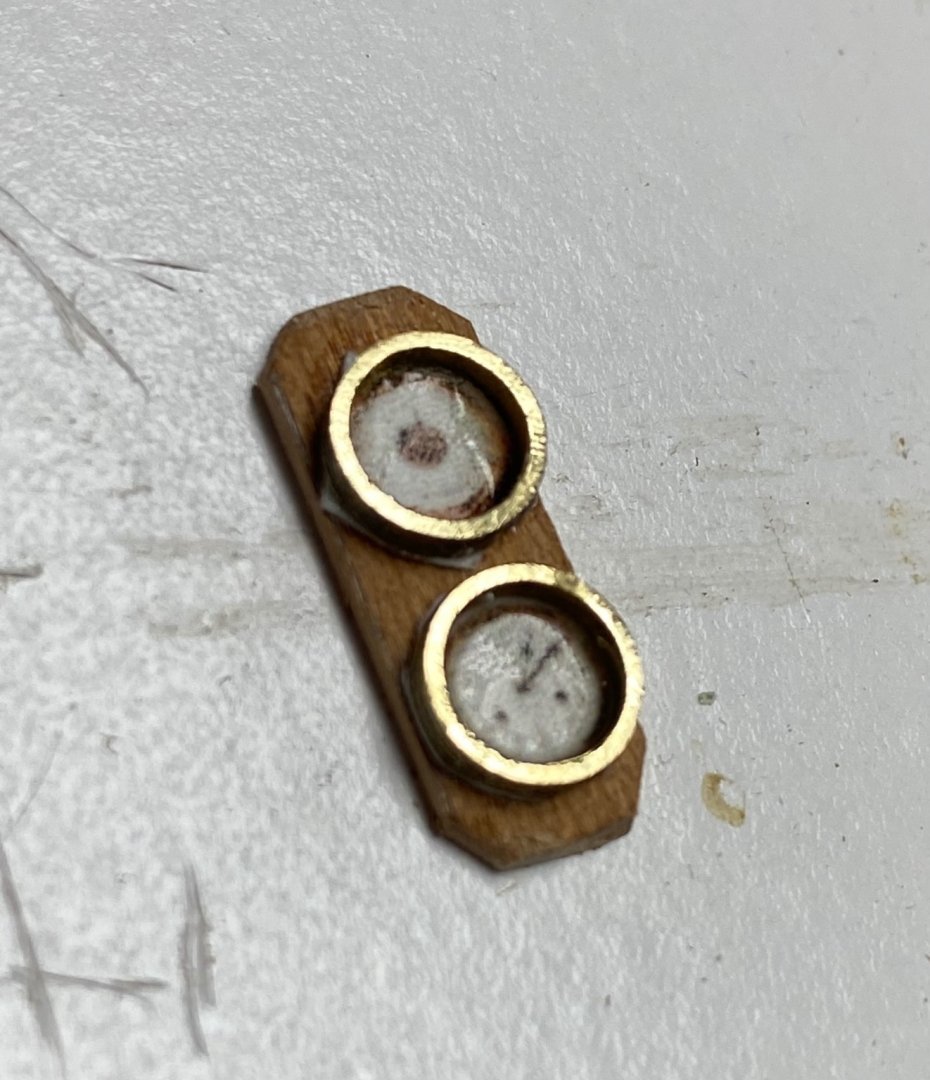
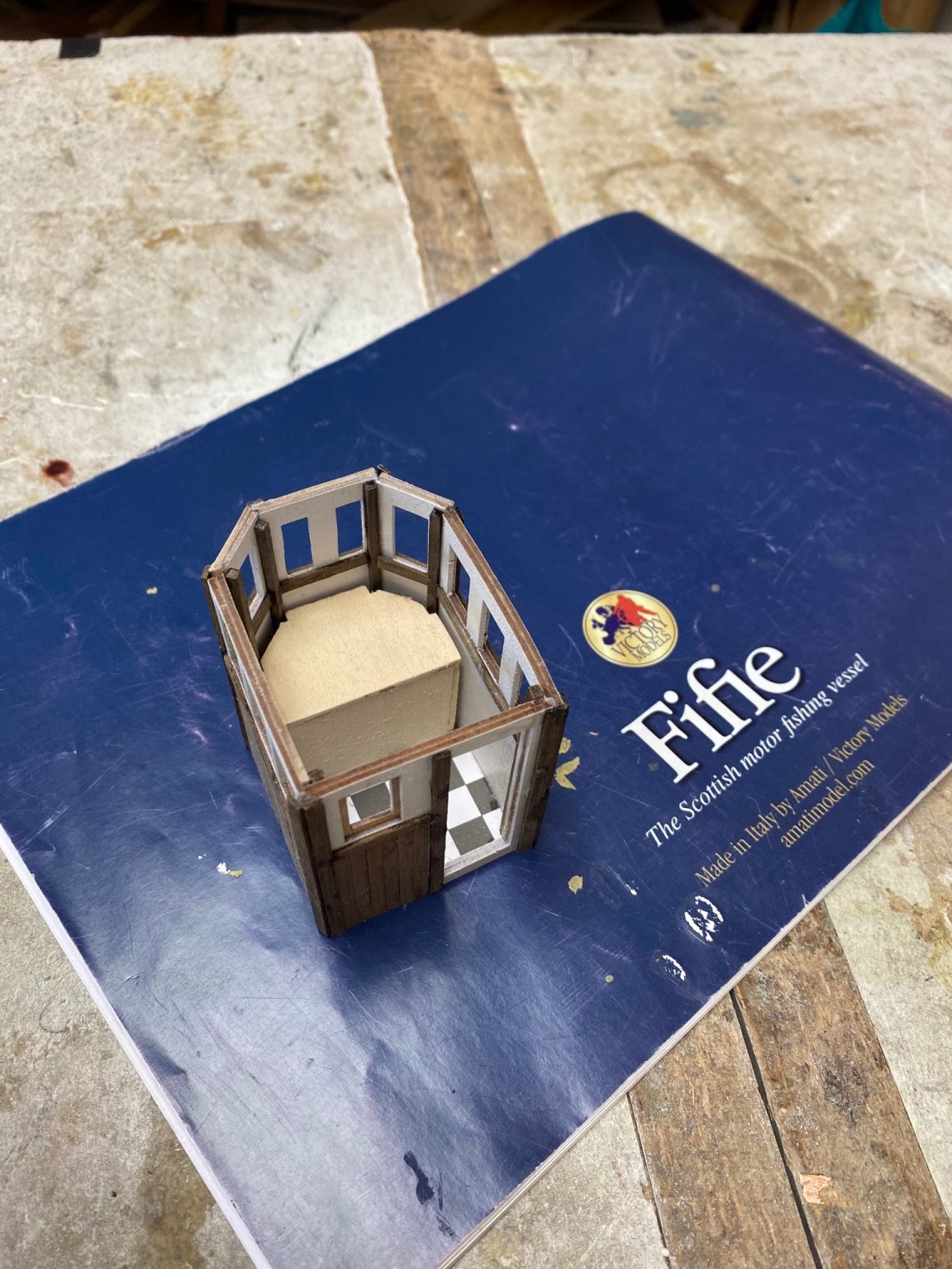
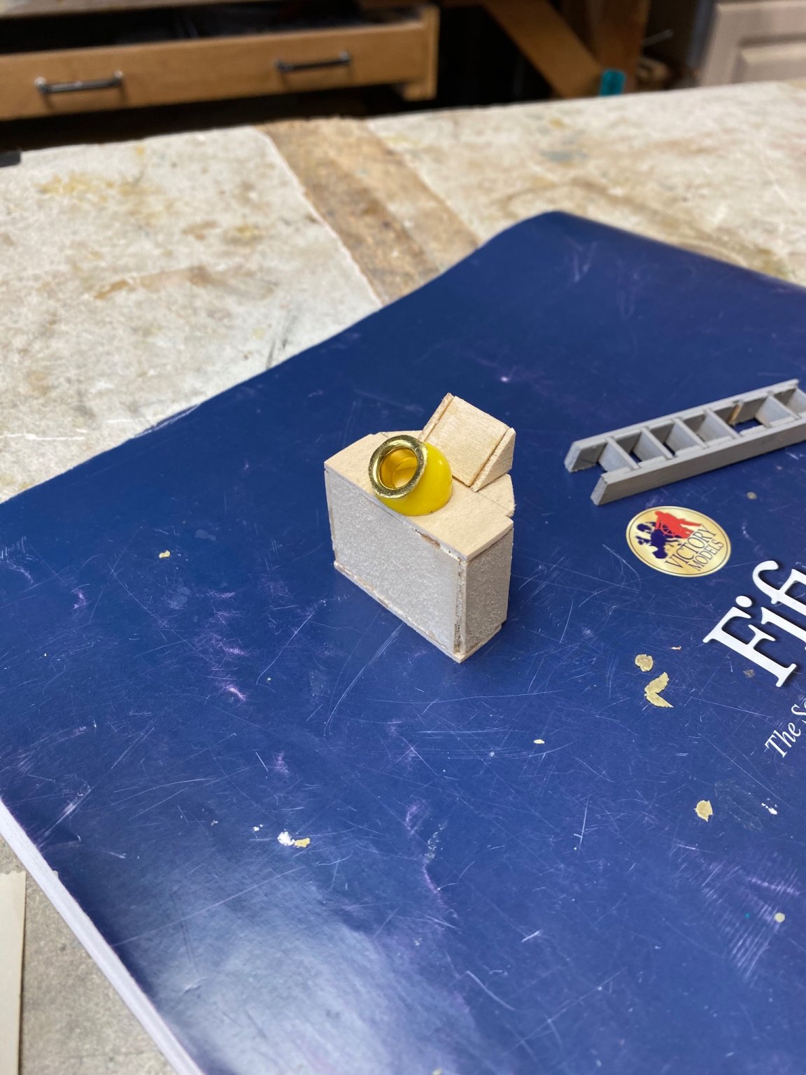
I am again taking a break from the ship's hull and doing some more detailing. I love details. Figuring out how to fabricate them is the pleasures of this hobby. I have not, and probably will never, manage to to do museum class miniature work. I am not a perfectionist and I don't hesitate to using available materials. That said, I am trying to "super detail" my pilot house. In a previous post I described how I fabricated the engine instrument panel but I still wanted a little more. I found a lot of scale brass mast rings in a box and figured that they will make great brass bezels for the instrument. Then I decided that, going on to the cold waters of the north sea, the fisherman will have to navigate using a compass (already furnished), a chart and a clock. Also, in those waters, weather changes dramatically and a barometer may be necessary. Therefore I decided to provide said necessities.
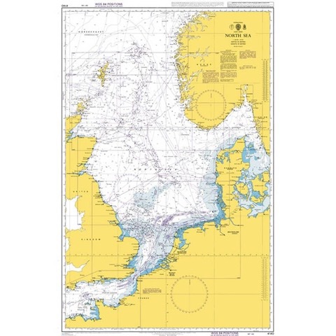
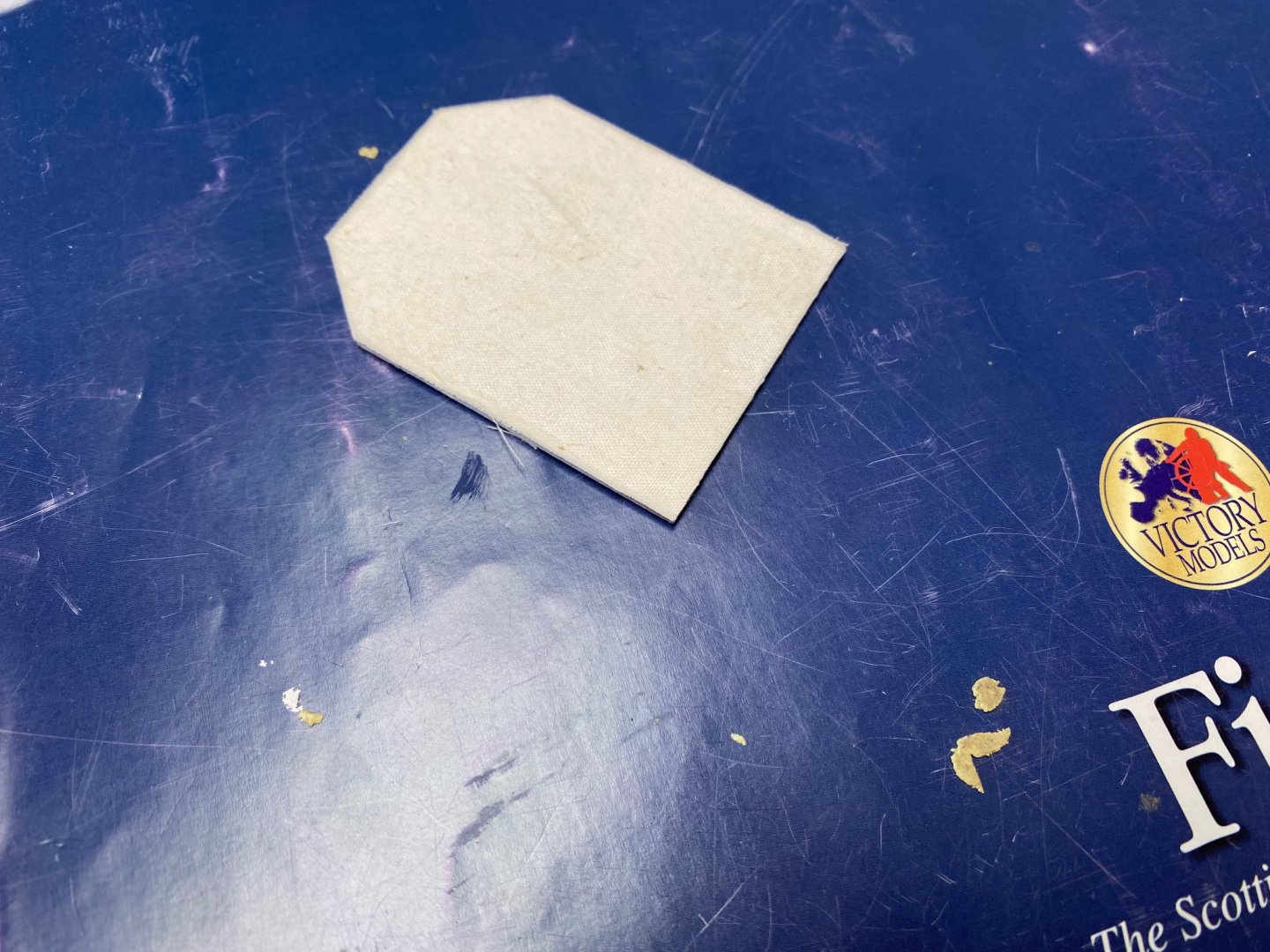
First we do the charts. I googled the fishing area charts and found several admiralty charts of the upper NE sections of Scotland including the northern isles. I downloaded some of the pictures and printed them reducing it to scale size.
Folded it down and set it on top of the instrument cabinet. Note: The pilot house is very small and should have had some space for a table.
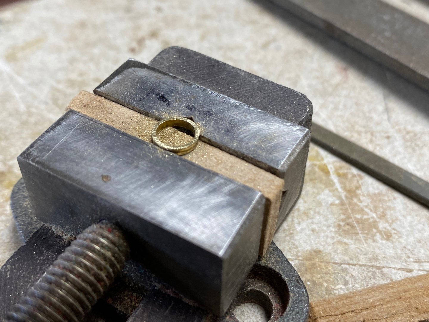
Then, I turned my attention to the gauges. In my case a 6" gauge will be reduced to 5 mm. The mast rings I found were of the same size (5mm) but looked too thick (2mm). So I had to shave at least 1mm off the ring. I made a parallel out of leftover wood and set the ring on my milling vise.
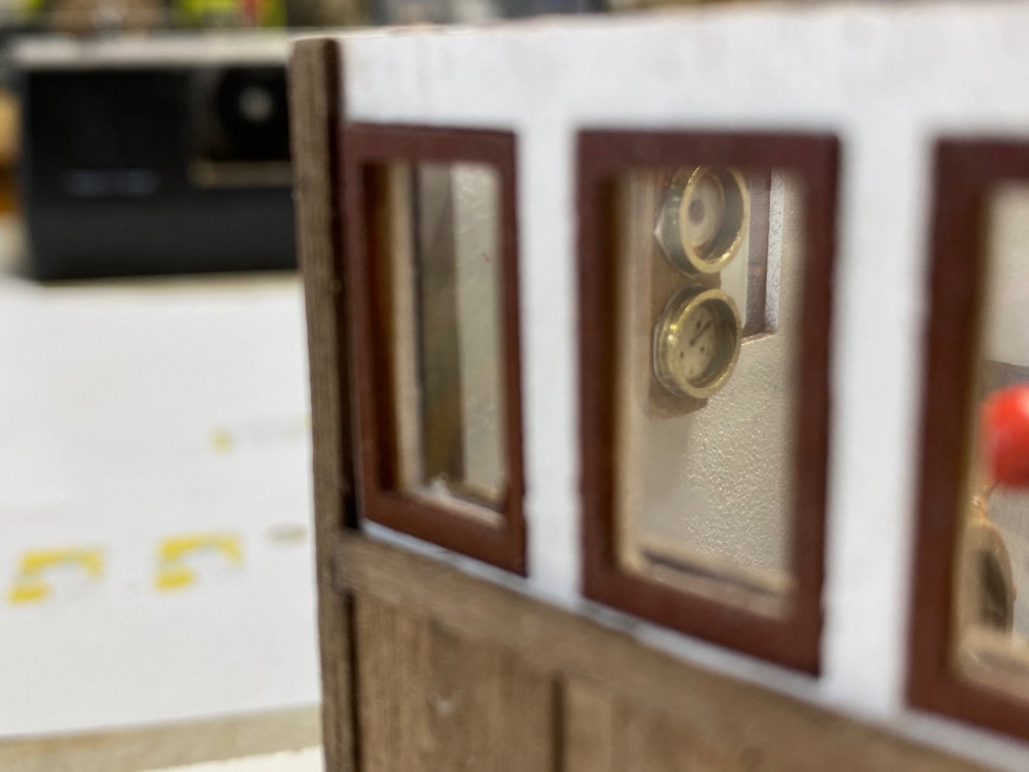
My reduced instrumentation was printed in glossy photo paper. The required printed gauge was cut, the bezels added and a wood base was cut from a slice of mahogany and installed in the only available wall space.

And it can even be seen from the side windows.
- JpR62, Rik Thistle, VTHokiEE and 4 others
-
 7
7
-
-
VTH, I started looking at you log because I am interested in also building the Alert. I am currently building the Fifie in 1/32. I also noted the communications with Chris Watton, whom I admire, and whose builds have help me in my own build. I welcome his comments on the new version of the Alert.
Like you, I used to call Lakeland my home for many years. Now I am retired and live in Bradenton and perhaps one of these days we will meet. I have read your first and last logs and I am very impressed. Thanks
- VTHokiEE and Ryland Craze
-
2
-
-
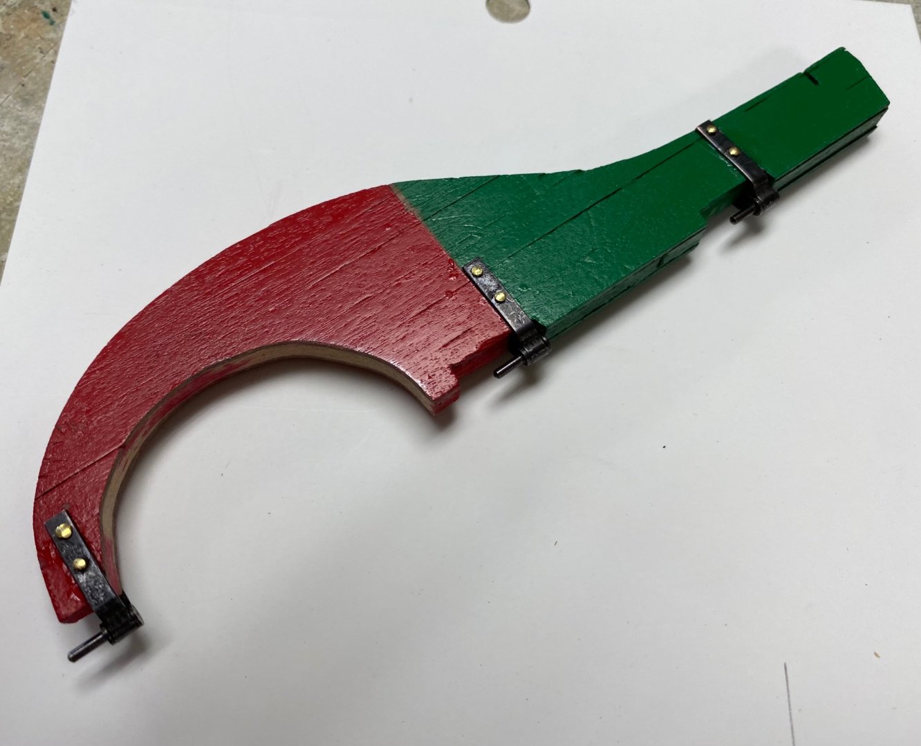
More progress but, I have to say, very slow. Started to work on the rudder and found that the hinges were not designed for the double planking. When I tried to re-shape one of them, it broke.
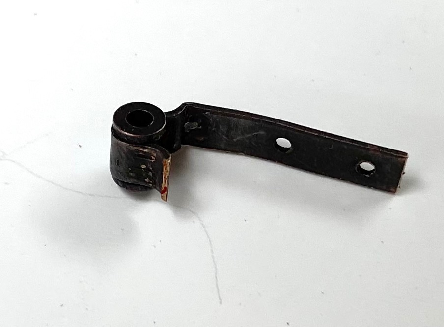
I figured that Amati did not count on the double planking. As a result I had carve out the upper layers.
This is the rudder with the hinges installed:
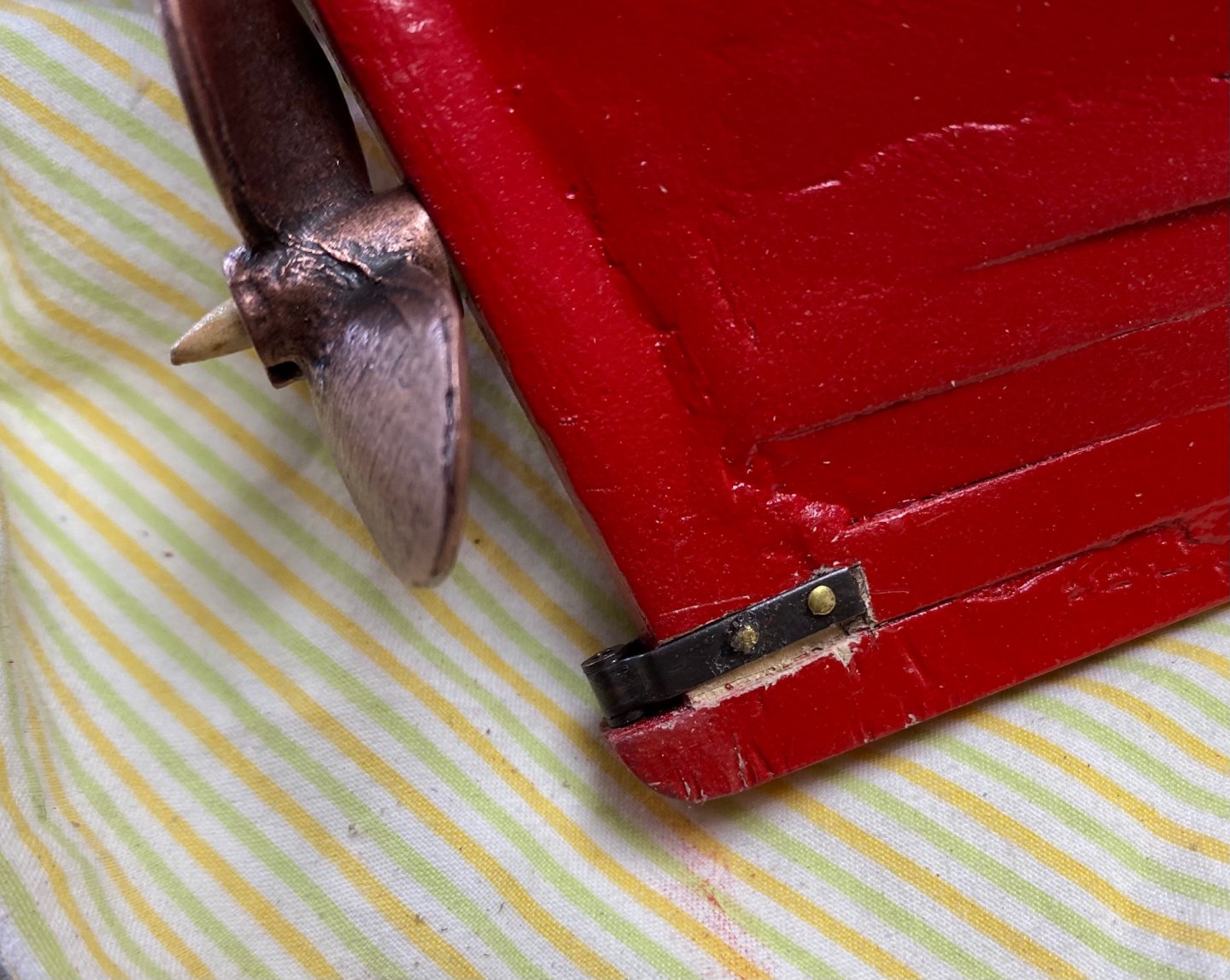
Then I found that the propeller supplied in the kit did not rotate when the rudder was presented to it. I had to file down the circular opening in the rudder to make it fit. Following is the result of almost four hours of work.
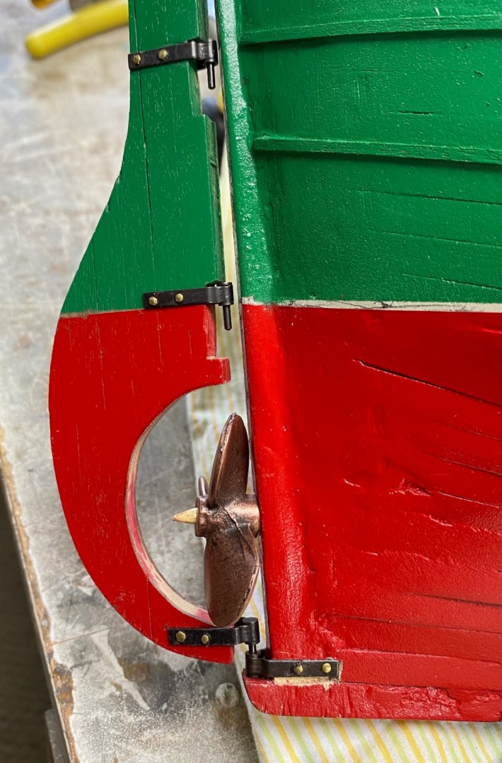
Still need to add the female portion of the hinges. This is going to require some more trim since the free space at the stern post is smaller than the hinges legs. I will probably cut the leg to fit. Details, details, details.
I should have paid more attention of what was coming while I fidgeted with the planking. Live and learn.
-
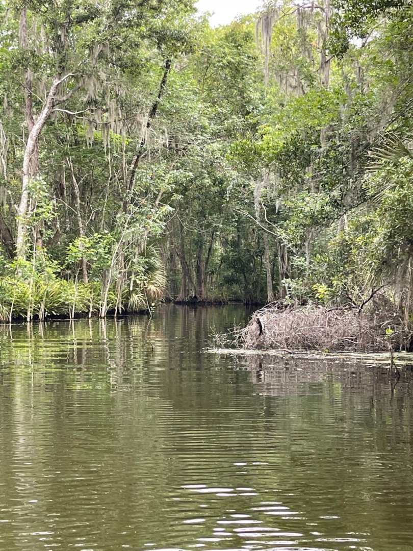
Just had a wonderful weekend navigating the rivers of central Florida. Lake County, properly named, connects with the world through the waters of the Oklawaha river joining the St. John river all the way to Jacksonville. We went through two locks; one of them had a 20 feet drop. The vegetation is typically tropical and gives you a sight of what Florida may have looked before tourists. This a photo of part of the river.
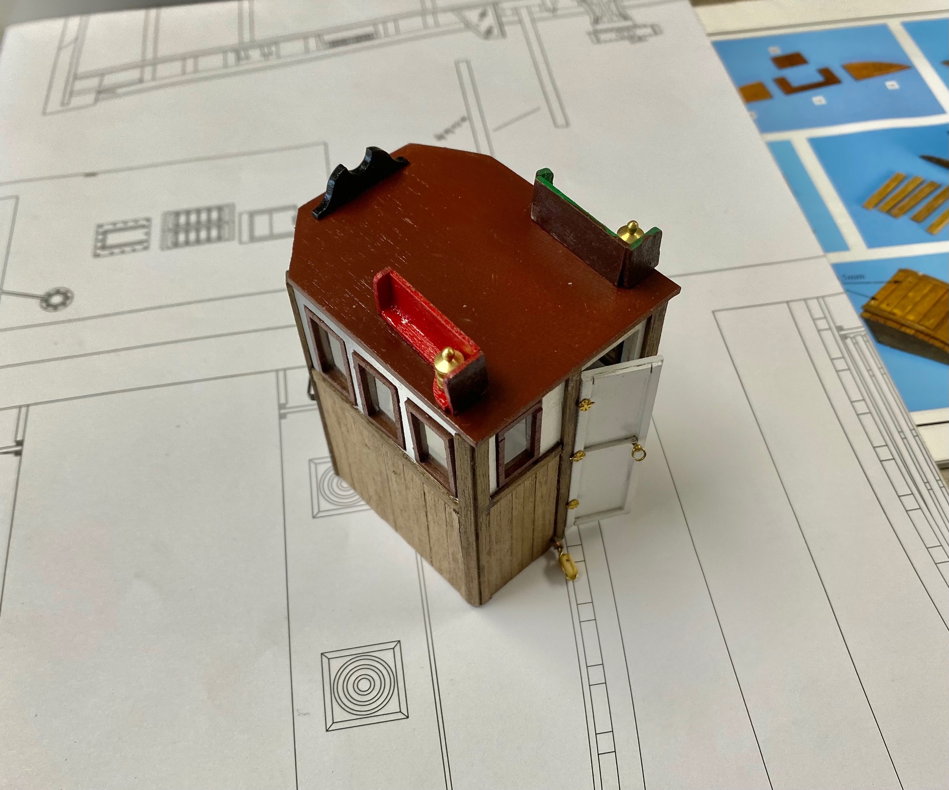
Back to the workbench. Continue working in the detailing of the pilot house and the aft superstructure.


BTW, I made the roof removable so that we can enjoy the helm. I think I am going to add a clock and a barometer. Need to figure where.
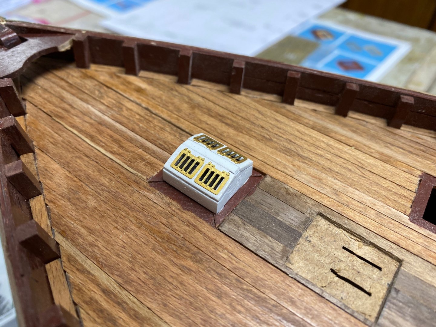
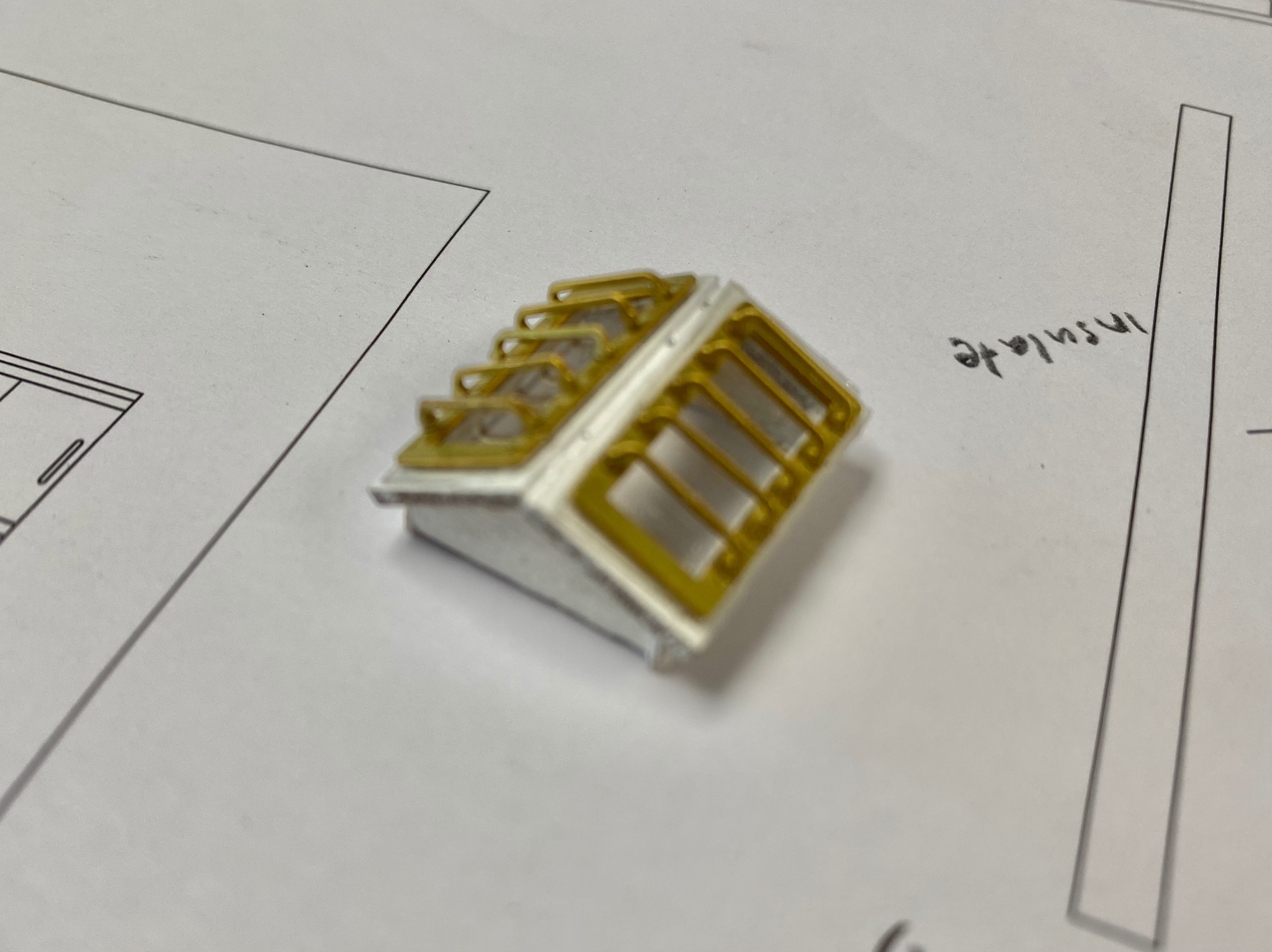
If I thought that planking was a difficult task, I never realized how hard it is to manipulate the tiny etched parts. This is the finished aft skylight.

And the fwd skylight
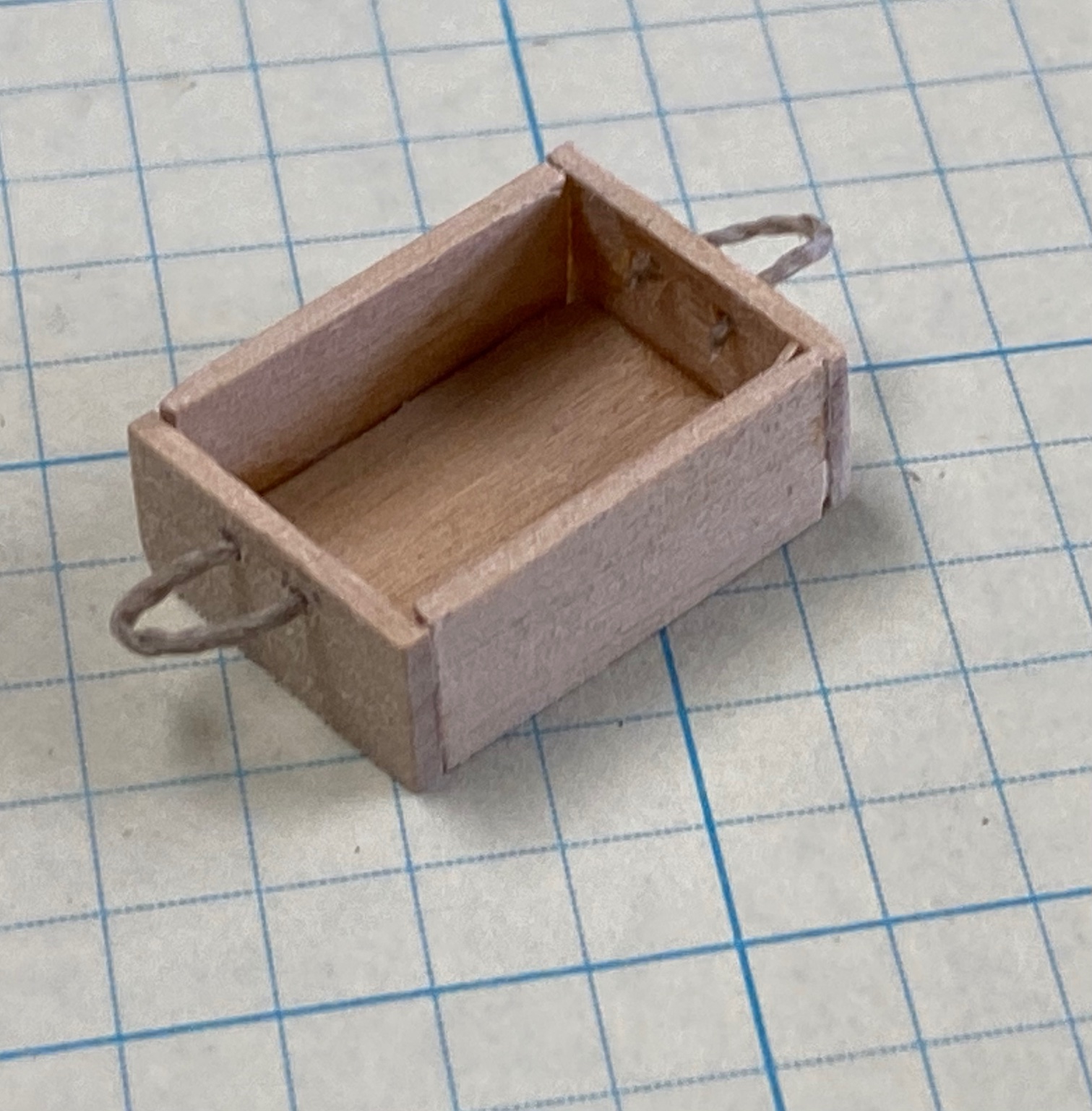
And then, in between skylights, I fabricated several wood crates that will be used to sort out the fish. They are tiny, the squares are 1/4".

Thanks for watching. I am having a ball while my wife plays shuffle board. LOL
-
Thanks Bob l. I love the details.
Ras
-
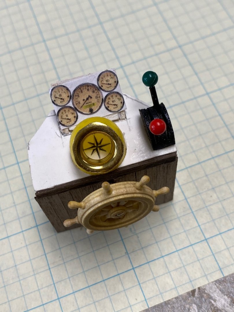
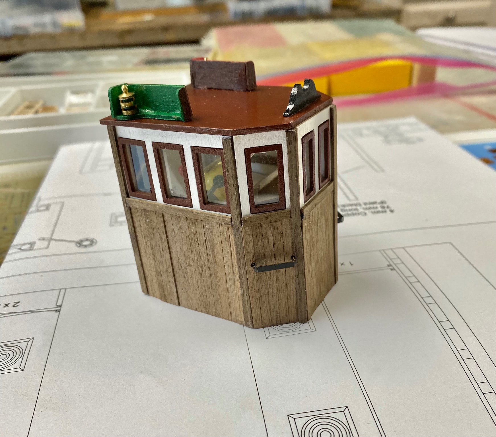
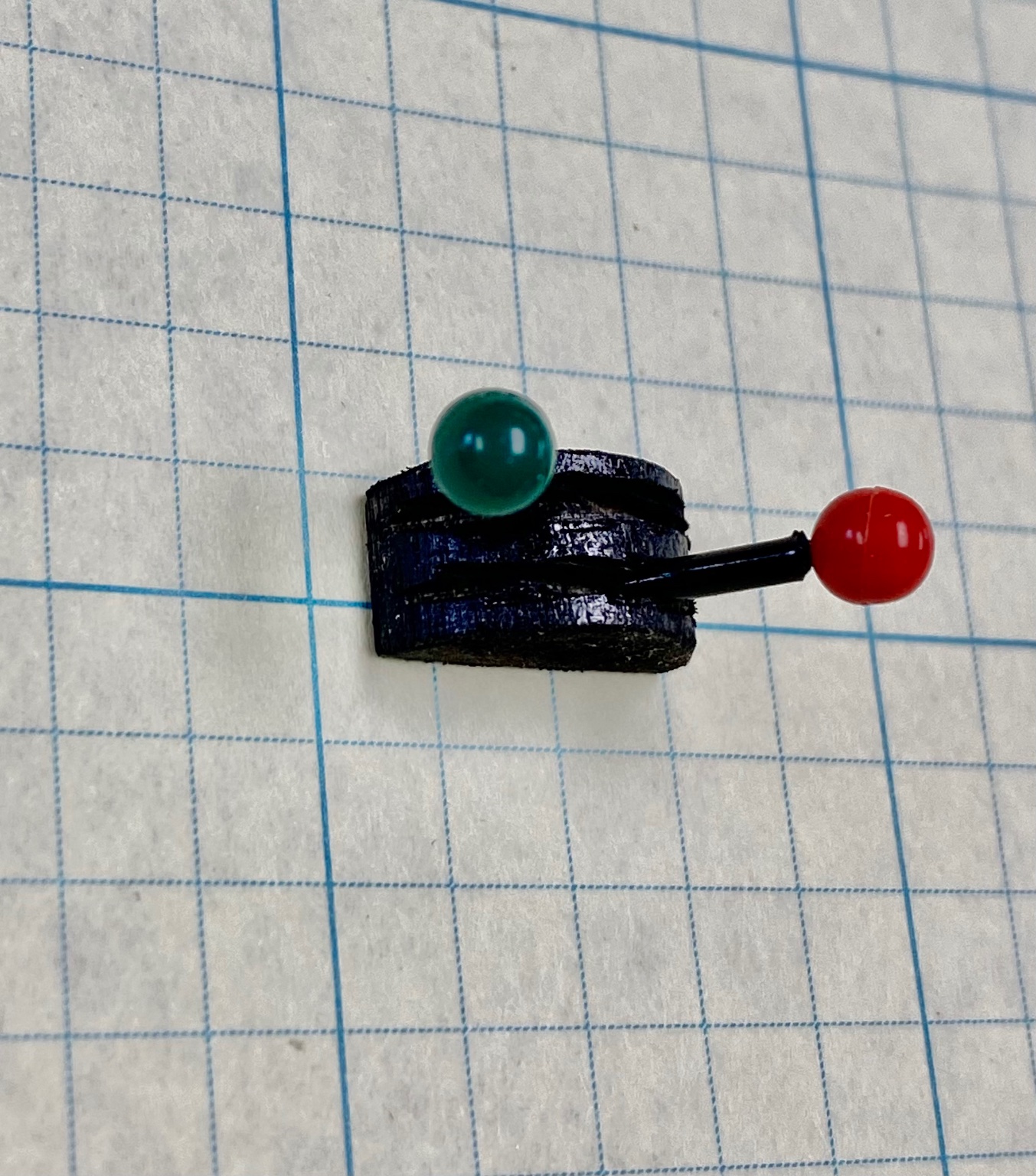
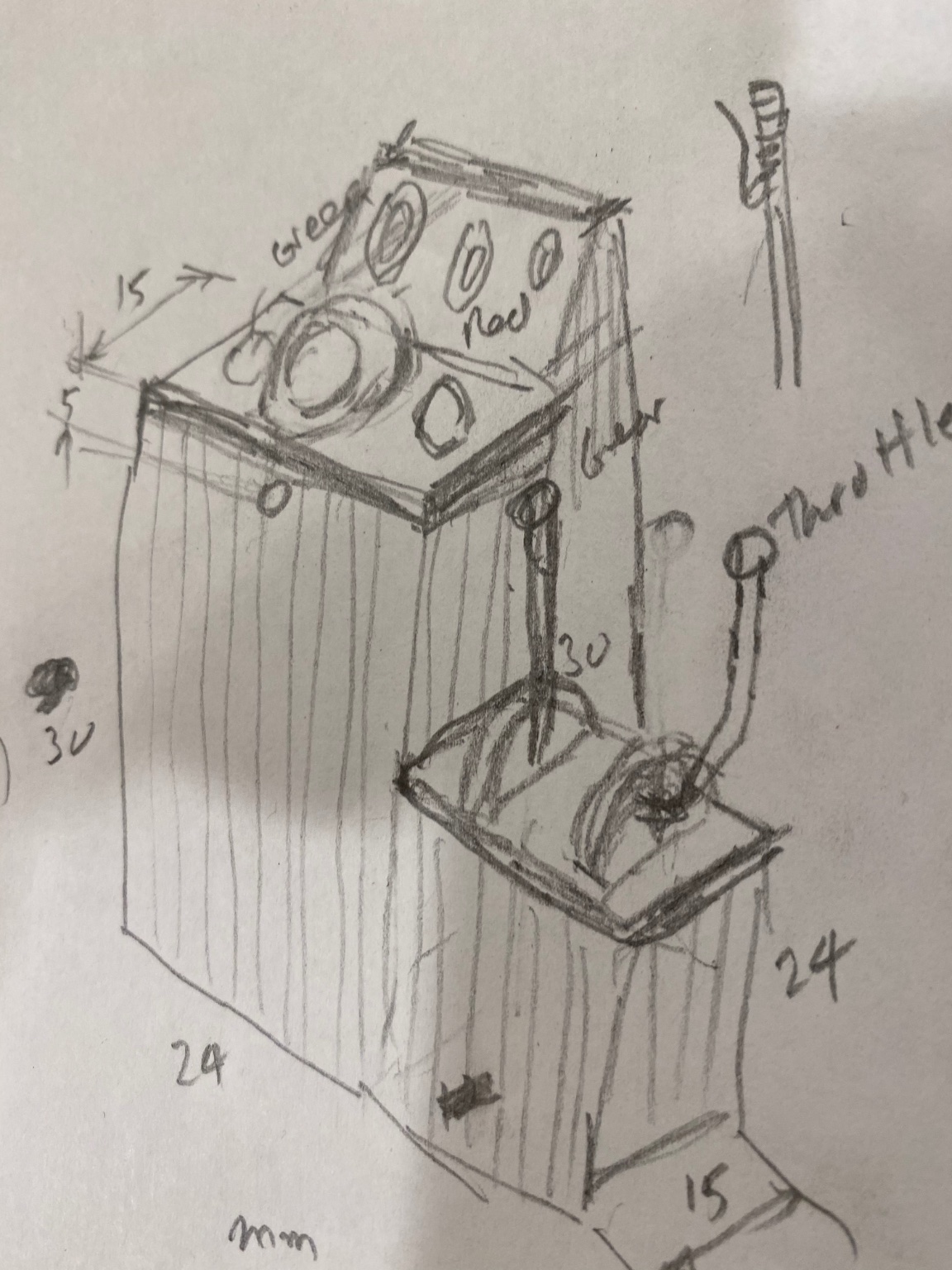
More on the pilot house. We have been wondering at the engine controls and have gone to several evolutions. This final one is this. It came relatively easy to build. I took a dowel and made a lengthwise cut in half. I sliced the half round like pepperoni and carved two grooves. The levers were made from map push pins and I selected Red (port) for gear and Green (starboard) for throttle.
This was the result:

The instruments were made using and online picture that I printed reduced to the 1/32 scale. The same with the compass rose. I installed the supplied wheel just to see the fit. I intend to fabricate in more reasonable wheel following PJG's build.
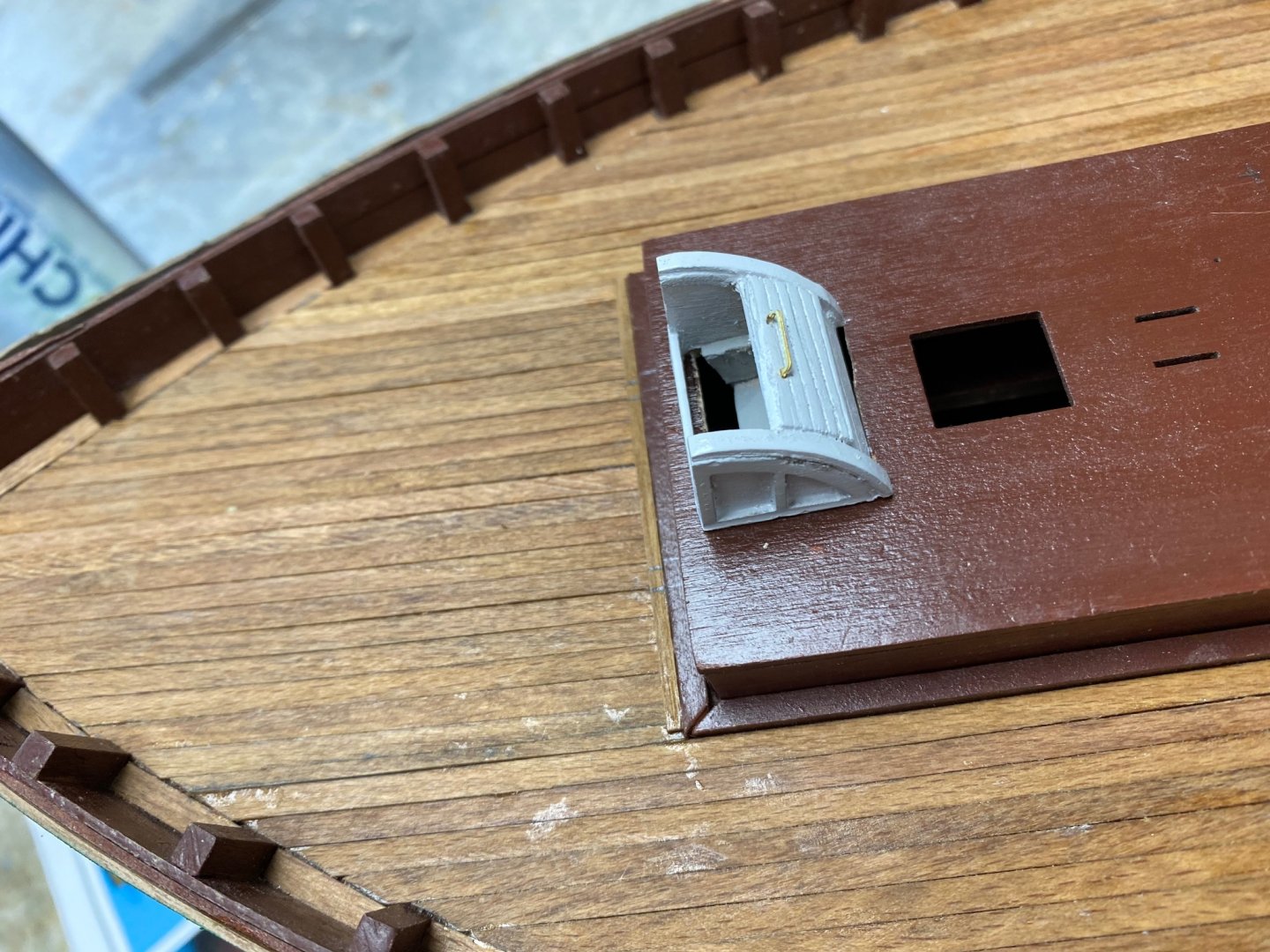
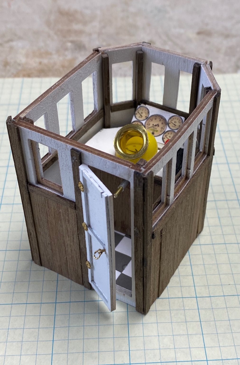
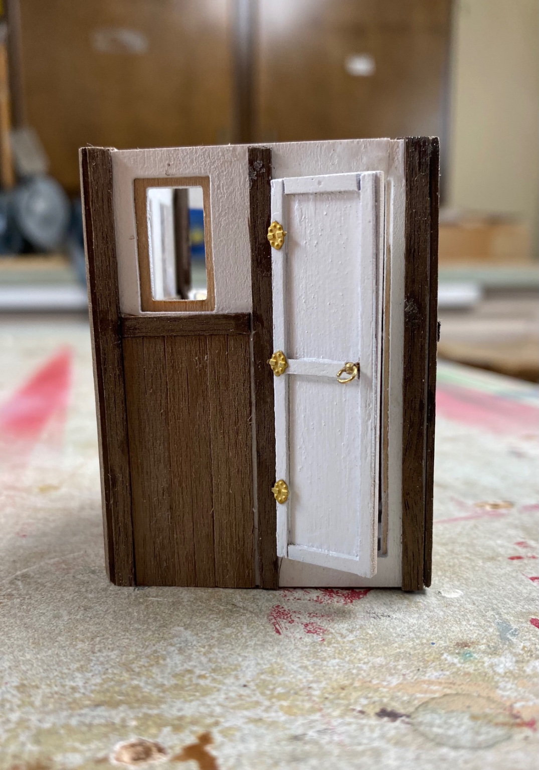
I then dry fitted the helm into the pilot house
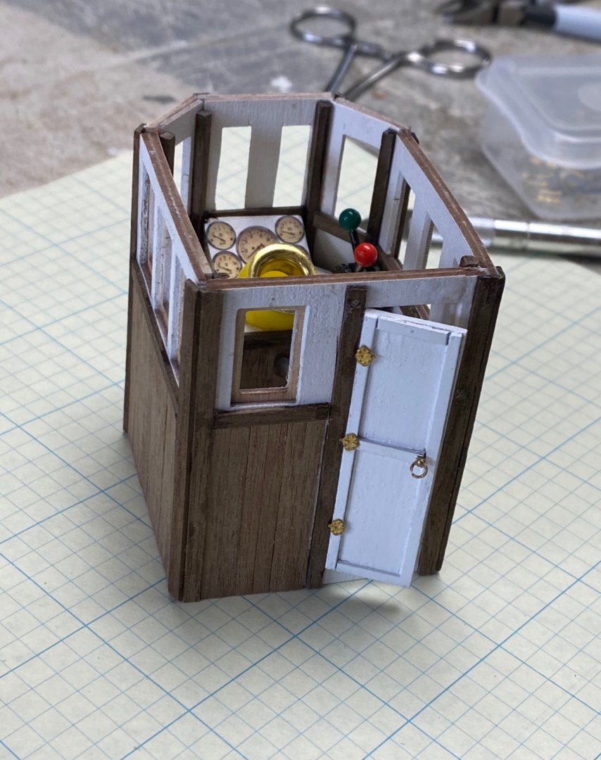

Noticed I also installed the door with its hardware and left it ajar.

Next I will finish the windows with the acetate and the frame. I also will make the roof removable so that, every once in a while, I may enjoy the insides.
As a matter of reference I want to tell you about another super detailed ship: the Eilean Mor. It is a Clyde puffer and Banjoman (the builder) has a pilot house detailed to the chart tools and even the pencil. He also has the coolest crew. He posted his build in "Model Boats" forum at modelboats.co.uk. I got a lot of ideas from him.
-
Brian:
Today I started to follow your built and I am overwhelm by you attention to detail and the history lesson that your build has. I am on page three of your build and will keep reading and learning from you. You have developed some really interesting techniques hat I will certainly applied to my own builds. Kudos to you.
Ras
-
Eamon:
You are obviously EU and I stand corrected. A Scottish vessel should have the green on the right and red on the left. We, "yankees", have the opposite. I found that out one day in Rotterdam when we were entering the river with a green marker on the right. I almost fainted thinking that we will be run aground.
BTW, in the US, we have the intercostal waterway which I frequently boat on. There, the red is to the land side while the green is to the ocean side. This make it very confusing to people not used to it. And then, if you leave the intercostal you must go back to " red, right, entering" which sometimes has a green and a red marker in the same place. Many a boater has been caught in this conundrum
-
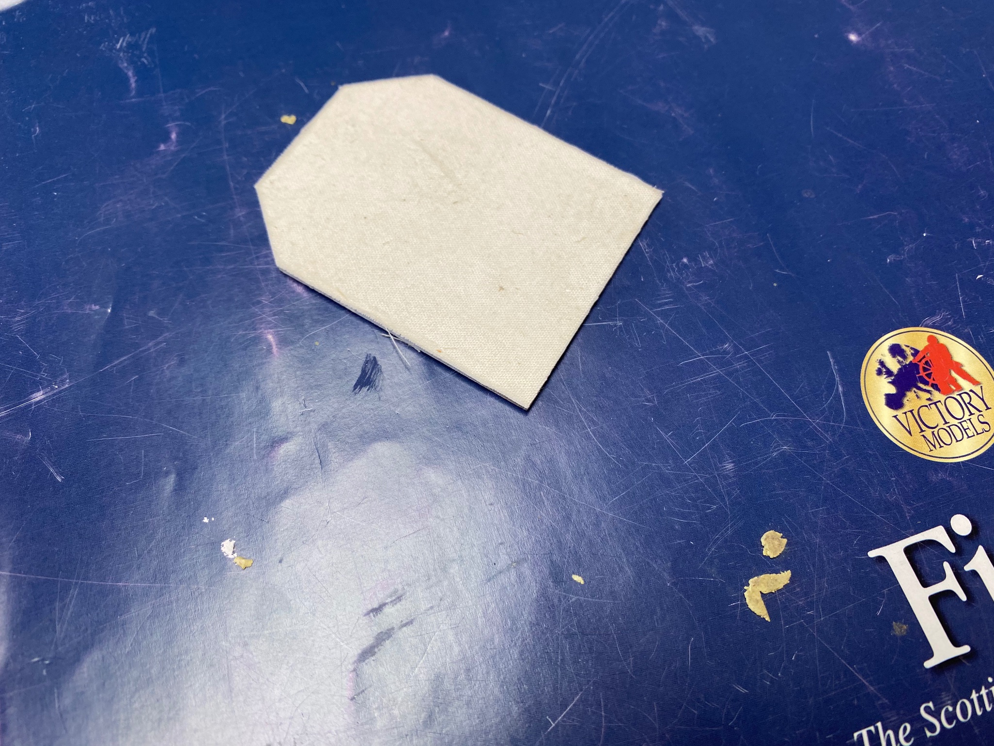
A little more progress. I tried to do the roof covering the same way I did my Patricia steam launch. This was to cover the roof with cloth to imitate tarps. I did this with the cloth provided by Amati for the sails, but, it seems that that the edges tend to unravel. I brushed some Elmers glue and will see tomorrow how it went.
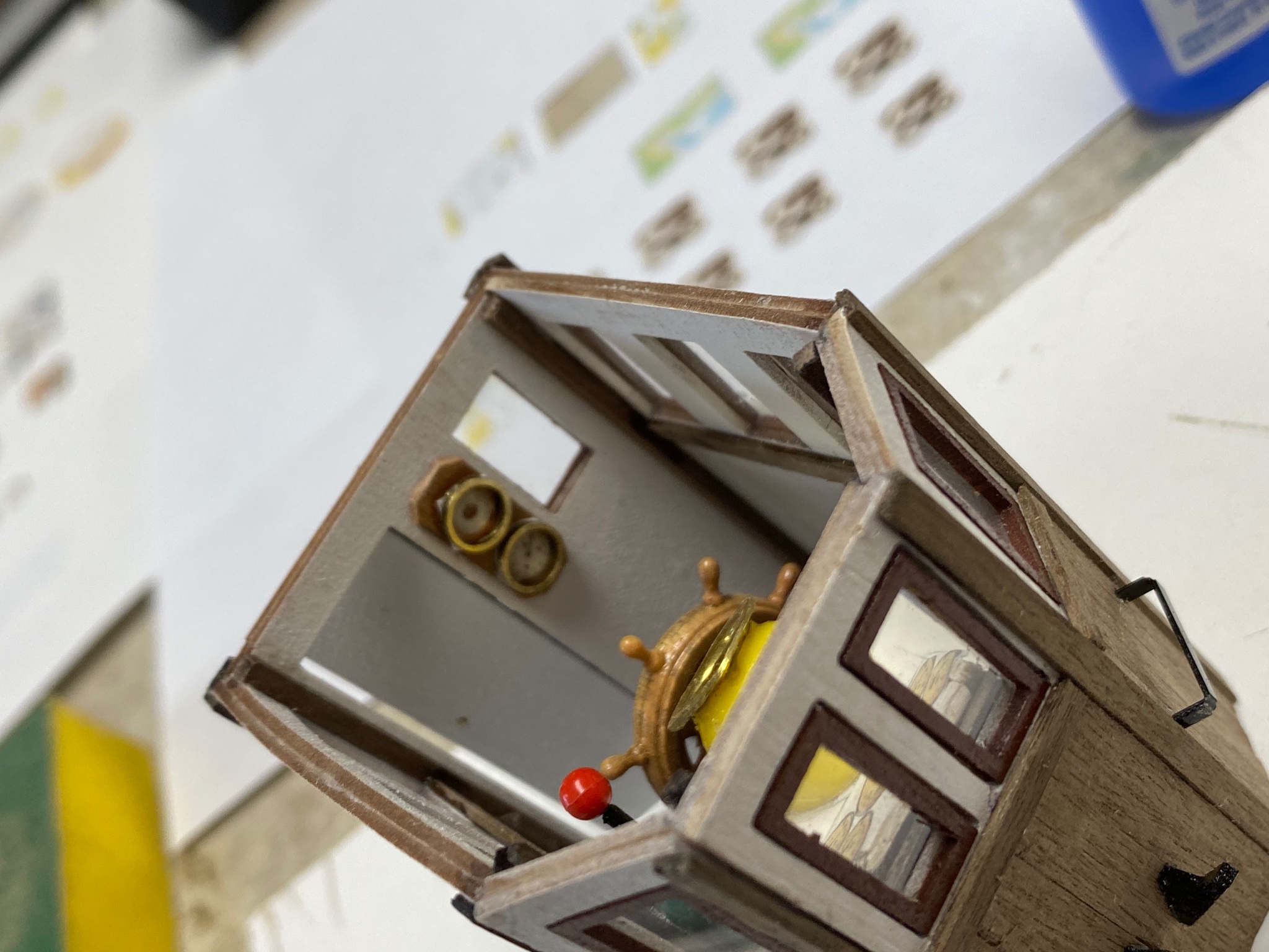
The big progress was in my pilot house. I built the helm as per my sketch but did not drop the top to make room for the throttle and the gear. I think it may look better to have these controls closer to the helmsman hands. Who knows? Basically, I didn't pay attention to my sketch and endeavored to fit this helm in the space available. So be it.

And this shows my previously made compass fitting nicely in front of the cabinet.

I have made mini-copies of vintage instruments and will glue them to the slanted part of the helm, in front of the compass. The compass will have his compass rose. I thought about bezels but I think I am getting miniaturization this too far. My eyes can't handle these ultra small stuff. Besides, you can hardly see these details once I set the roof over it.
Finally, I am looking for something that resembles formica to cover the top. The sides will be planked with my leftover from the outside if the pilot house.
Thanks for watching and I love to hear your comments and/or advise. FYI, my Patricia launch took me 5 years to complete as I had tremendous lapses in my construction time. Your interest has inspired in me this desire to finish this boat and the go into another build. I am having a ball.
- Rik Thistle, egkb, BobG and 1 other
-
4
-
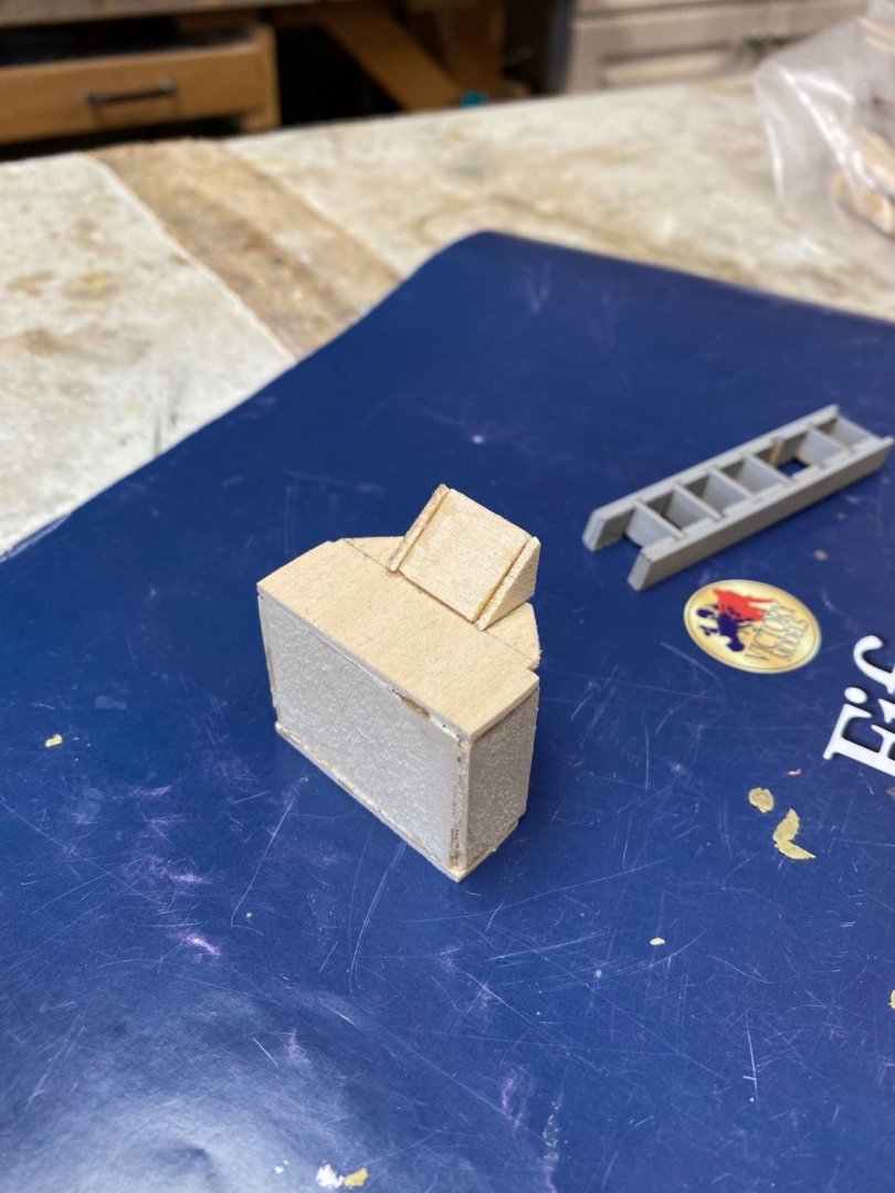
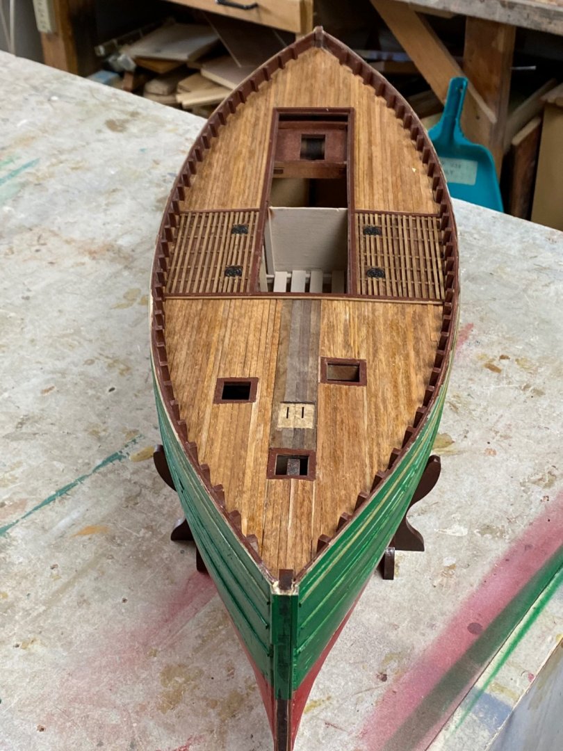
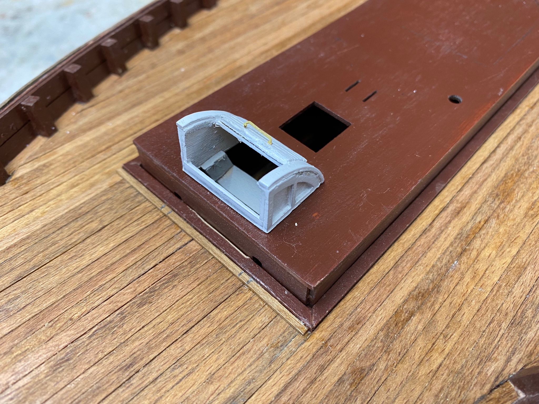
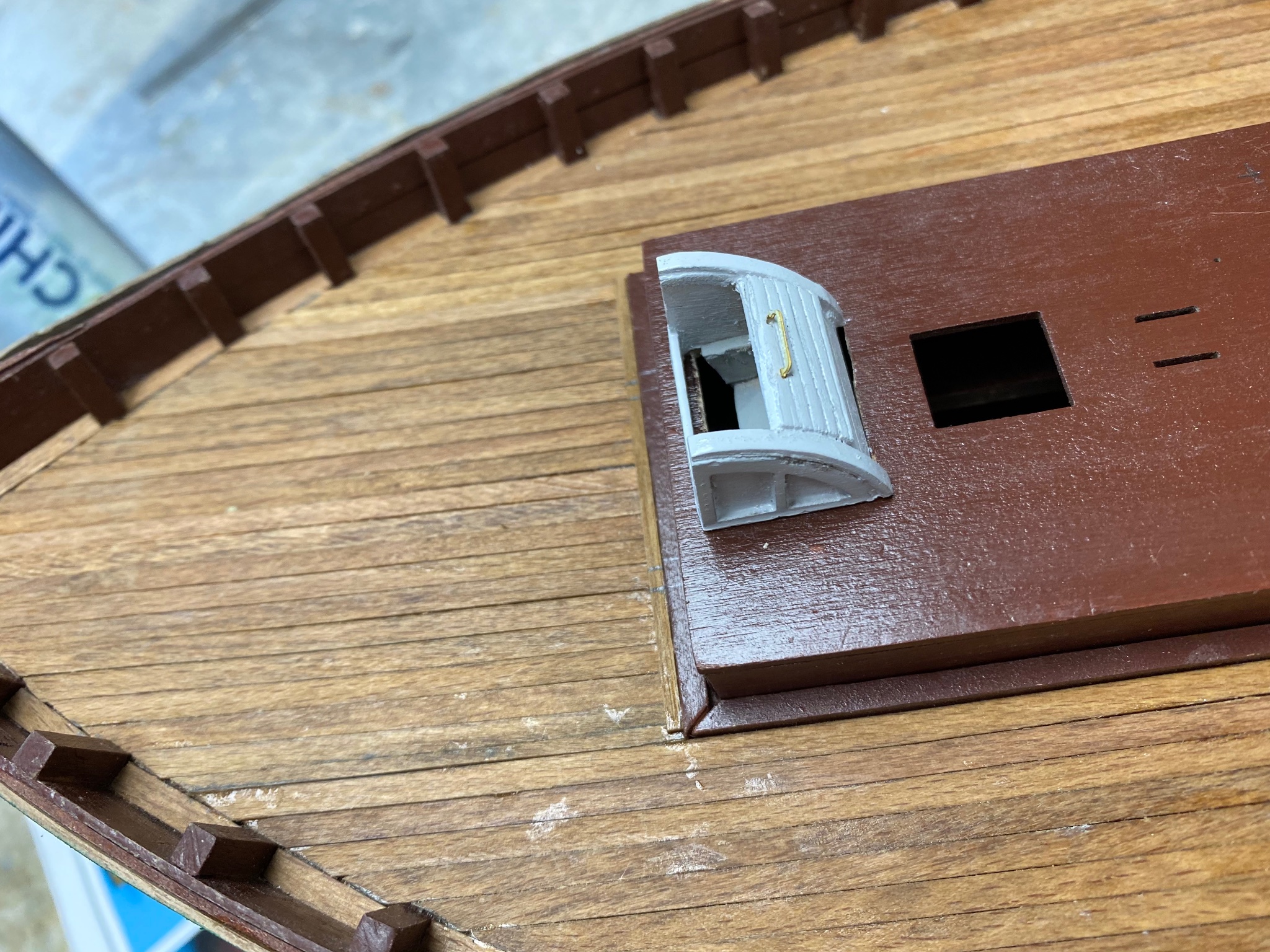
Little progress. I dry fitted the ladder and the aft companionway and you can hardly see the ladder. When I install the door, which is already fabricated, the ladder will be invisible. So much Effort!

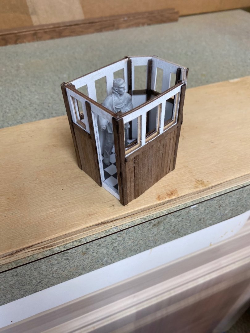
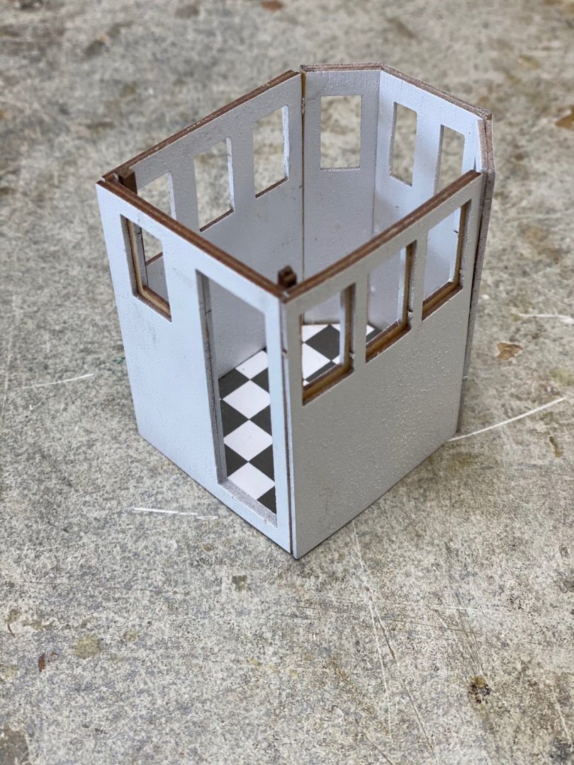
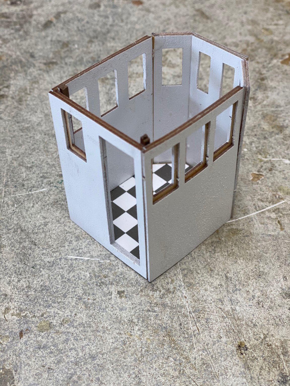
I have also been working on the pilothouse and I am pleased with the results.
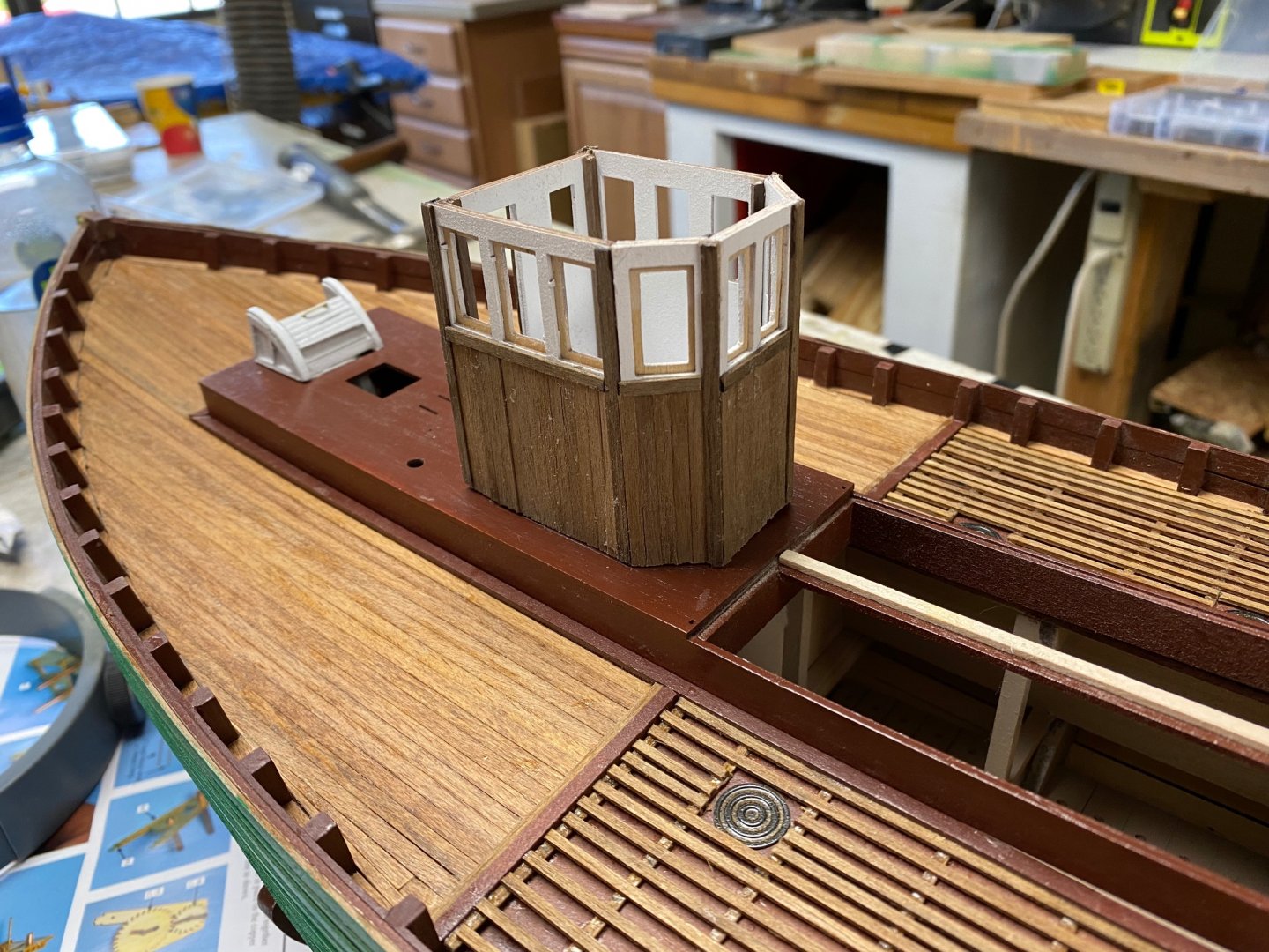
I placed one my figures inside and it sure look tight. These pilot houses were mainly designed to protect the helmsman from the weather. Be it as it may, the figure is actually to scale 1/30 which translate in a guy 6'-6" tall. I bought these figures in France (See my previous posts) and they are beautiful. I also bought some figures from Tamiya but they are 1/35 scale which makes a 5'-4" fellow. I figured Scots as really tall and brave guys so I'll use my frenchies. Besides, I only intend to man the deck.
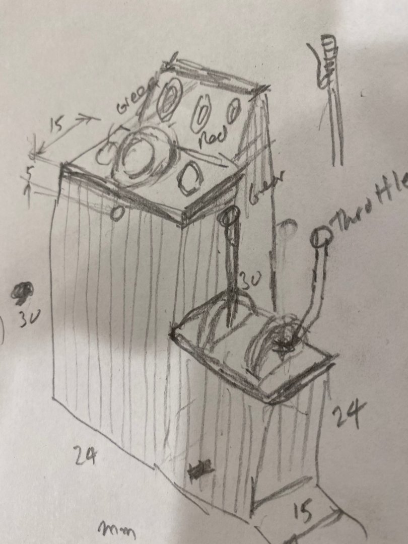
Also been thinking about the helm. The mechanism provided by Amati seems very complex for something that will be literally hidden inside the pilothouse. I have been following PJG's built and have come out with the following idea: To build a wood encased helm that will include levers for gear and throttle, the compass and the engine instruments. Pardon the scribbling in my sketch, Will appreciate your comments.
-
-
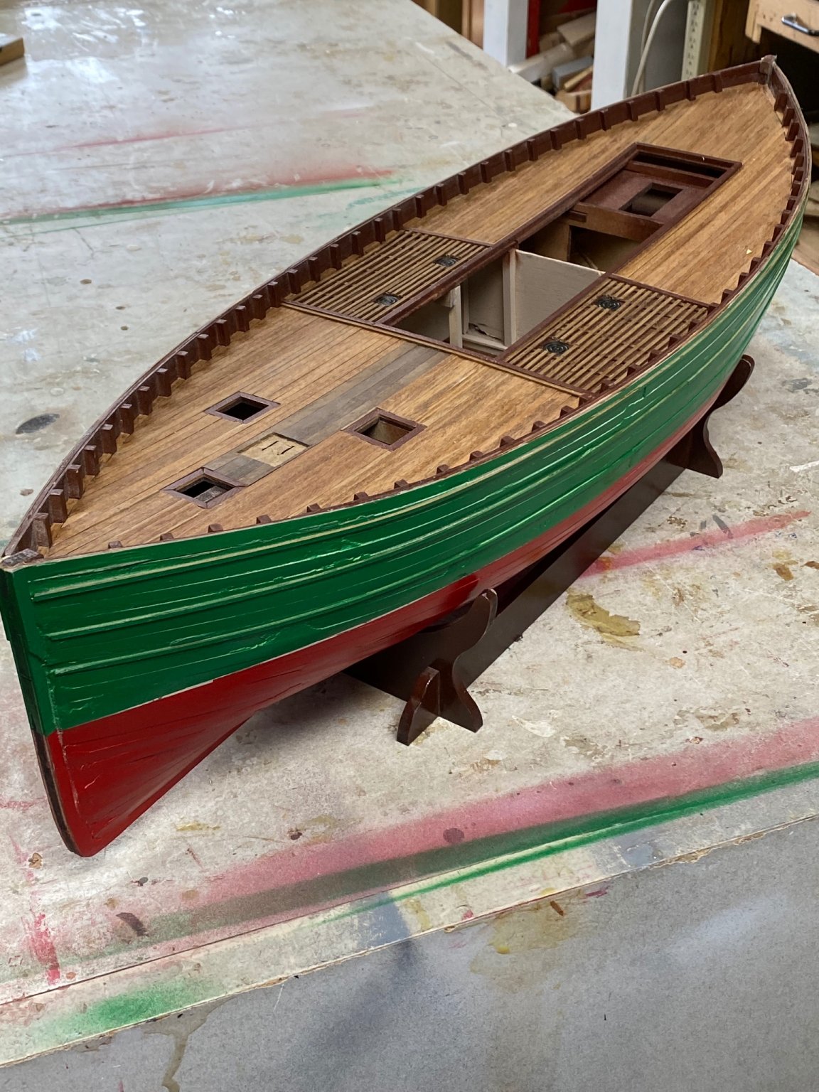
The hull planking and painting is finished. However I still need to attach the gunnel rail. Starting work on the pilot house.
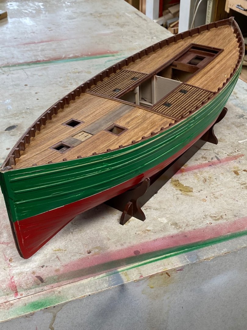
You may be able to see some of my booboos but I think that, for a poor man's boat (the fisherman), they give some reality to the ship.
And then the pilot house. I am working on a layout for the controls of the ship following the work of Big Dan. Thanks for watching, I am having a ball.
-
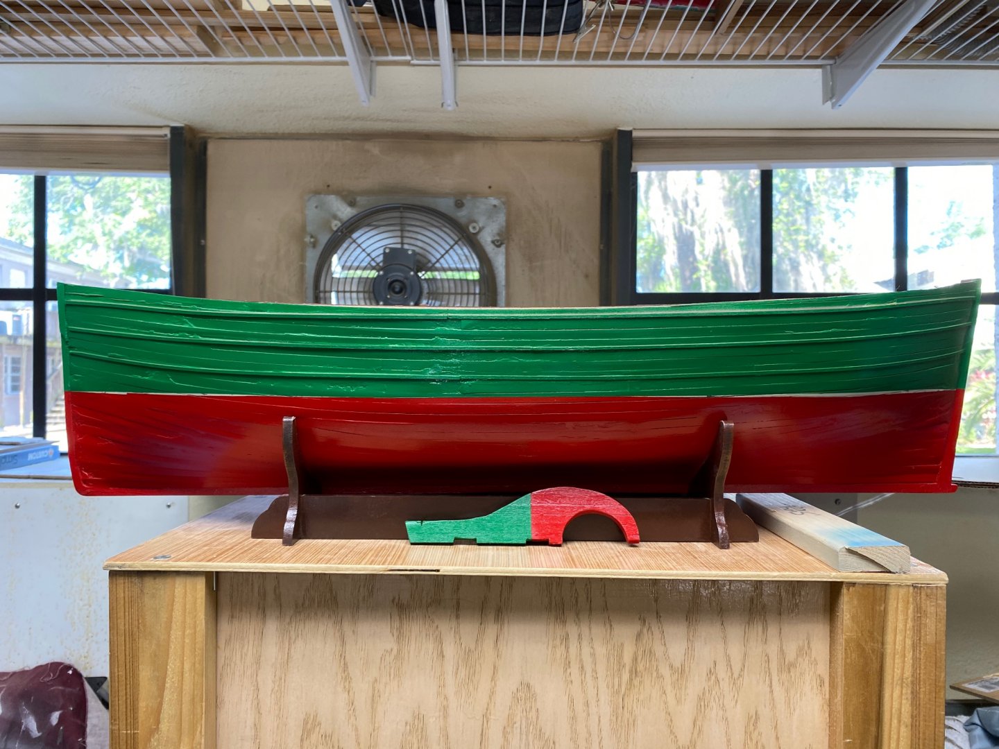
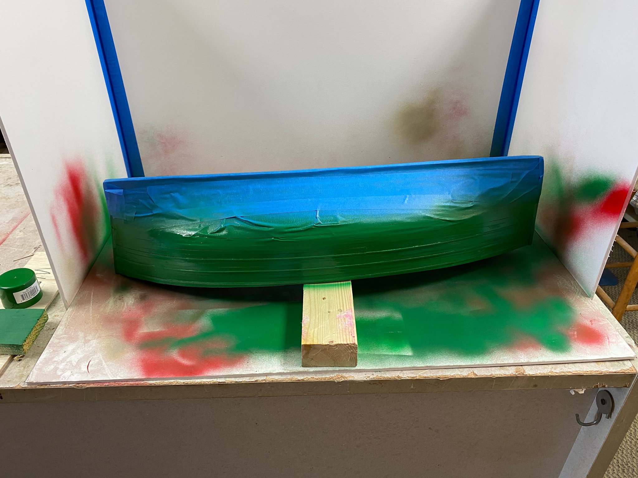
Well the hull painting is done.
First the bottom
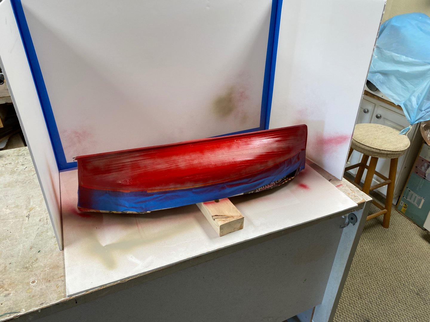
Then, the top

I was going to start the hull painting with the fat white waterline, but I found a little difference between the port and starboard rub strakes. This was due to the asymmetry of my planking. I plan now on a slimmer line made with chart tape.
Have also been doing the preliminary work on the pilot house. We will cover this later.
-
Beautiful job Steven. I have a couple of questions. First: what did you use to round off the hull. An english wheel perhaps? OR did you made a wood mandrel to hammer at? Second: how thick is the meta you used. I am asking because I would love to to do the same ship in metal. I am from Cuba and the USS Maine is part of our history.
-
Thanks E. I promise to do better next time.
-
In the last week I have completed the planking of the Fifie. Had some trouble with the fairing of the frames and the tapering of the planks. At Chris's suggestion I have bought NRG's tutorial for hull planking. I now have the kit and it is going to be fun to learn the old ways.
Here is the last plank
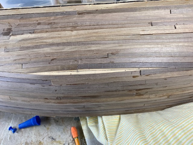
Planking done
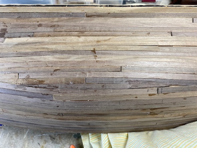
Filled, sand and primed

The priming brings in some additional booboos. Some will be filled and sanded but I will have to live with the others. So is life. Besides these boats used to be made in poor shipyards and they were for poor fishermen so....
For the newbies information. I used Miliput for the first time and have to say it is fantastic. Lots of possibilities with this material.
- yvesvidal, egkb, Ryland Craze and 1 other
-
4
-
-
-
-
Sorry about my last post. I didn't realize that Dan had passed away. My condolences.
- Canute, Egilman, popeye the sailor and 1 other
-
4


Fifie by Ras Ambrioso - FINISHED - Amati - 1/32 scale
in - Kit build logs for subjects built from 1901 - Present Day
Posted
A little more progress. Fabricated the fresh water tank and the rope hatch. Working on the bulwark inside strake (I don't know the nautical term. Had a lot of trouble lining up the roller brackets. Too small for my fingers.