


Ras Ambrioso
-
Posts
603 -
Joined
-
Last visited
Content Type
Profiles
Forums
Gallery
Events
Posts posted by Ras Ambrioso
-
-
In the fifie I’m building, the steam winch had EP wheel installed. the Ep card had an extra one. They are a about 2.5 mm dia. I think these would be available on line
- Eurus, Keith Black and mtaylor
-
 3
3
-
-
Guys this last thread about the aileron horns is another reason I love this forum. We are not only modelers but historians. Thanks you guys.
- Egilman, thibaultron, mtaylor and 6 others
-
9
-
-
Thanks Cathead. I have been inspired by other builds in this forum. I am trying to build something a little different than just an "out of the box" kit. For my next adventure I am going to try a "scratch" build. But, I'll tell you these details are what makes it fun. I am going to make nets and improve on my fish. The boat will be presented as ready to unload crans of herring. Bumpers out, mooring lines ready and hold partially open etc, etc. Chris Coyle, PJG and Big Dan have been great models to follow.
-
Ives, I will be following your built closely. First, I have considered building the Flower corvette model for a long time and second, I am very interested in the 3D printing. Your comments on my build are always appreciated. Keep up the good work.
- yvesvidal, CDW, popeye the sailor and 5 others
-
8
-
-
Chris: just by chance I got into your posting. I love your work and I am waiting to finish my Fifie to start the V108 and get into the card business. The Halinski Spitfire wire beckons.
- thibaultron, Egilman, Edwardkenway and 5 others
-
8
-
-
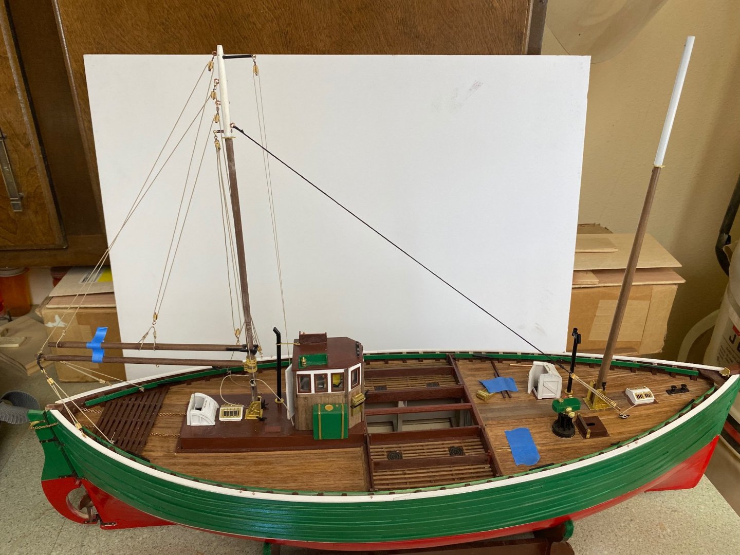
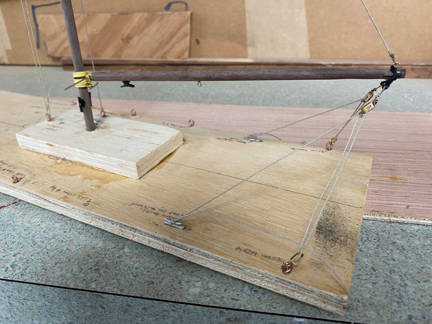
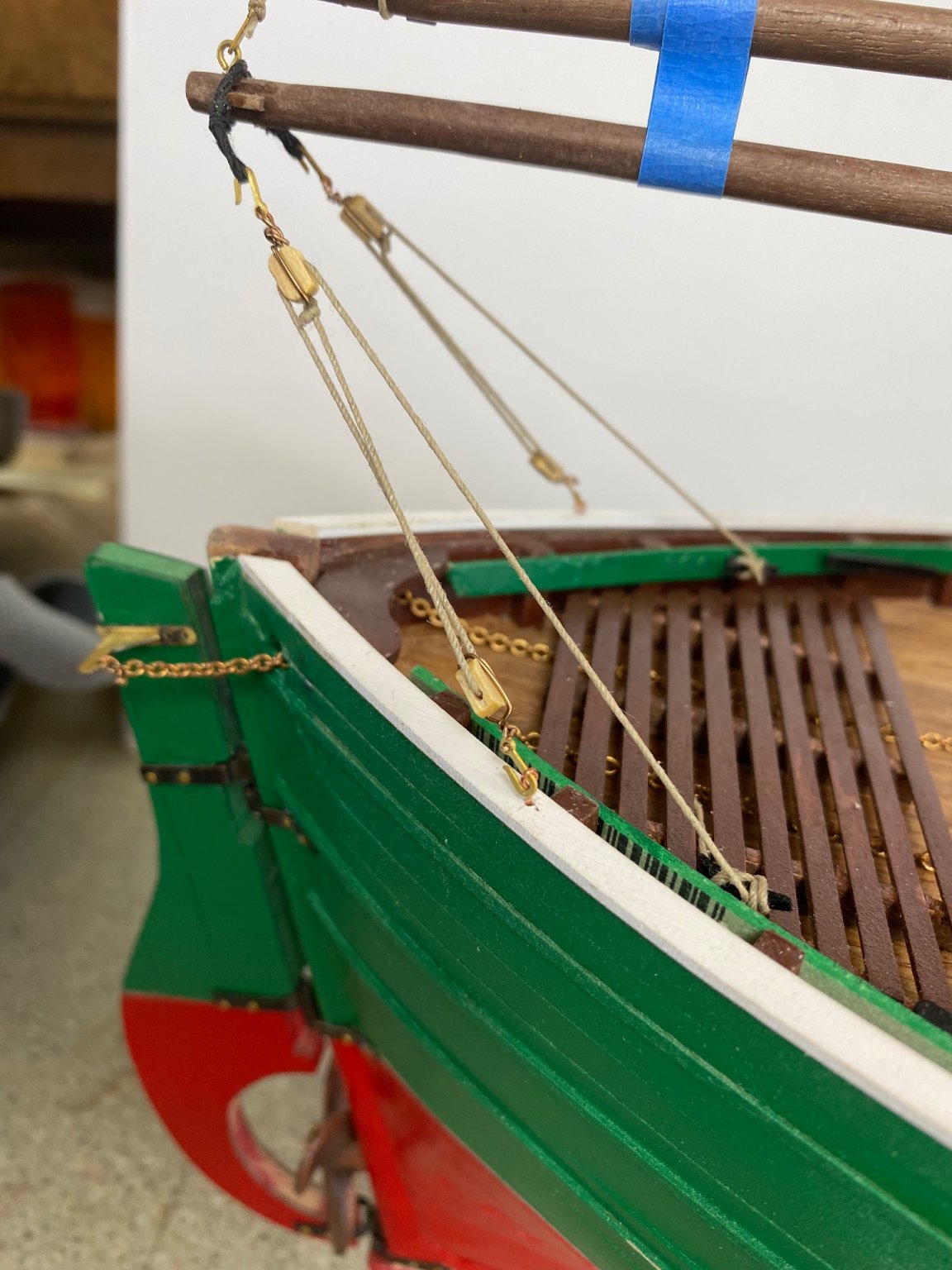
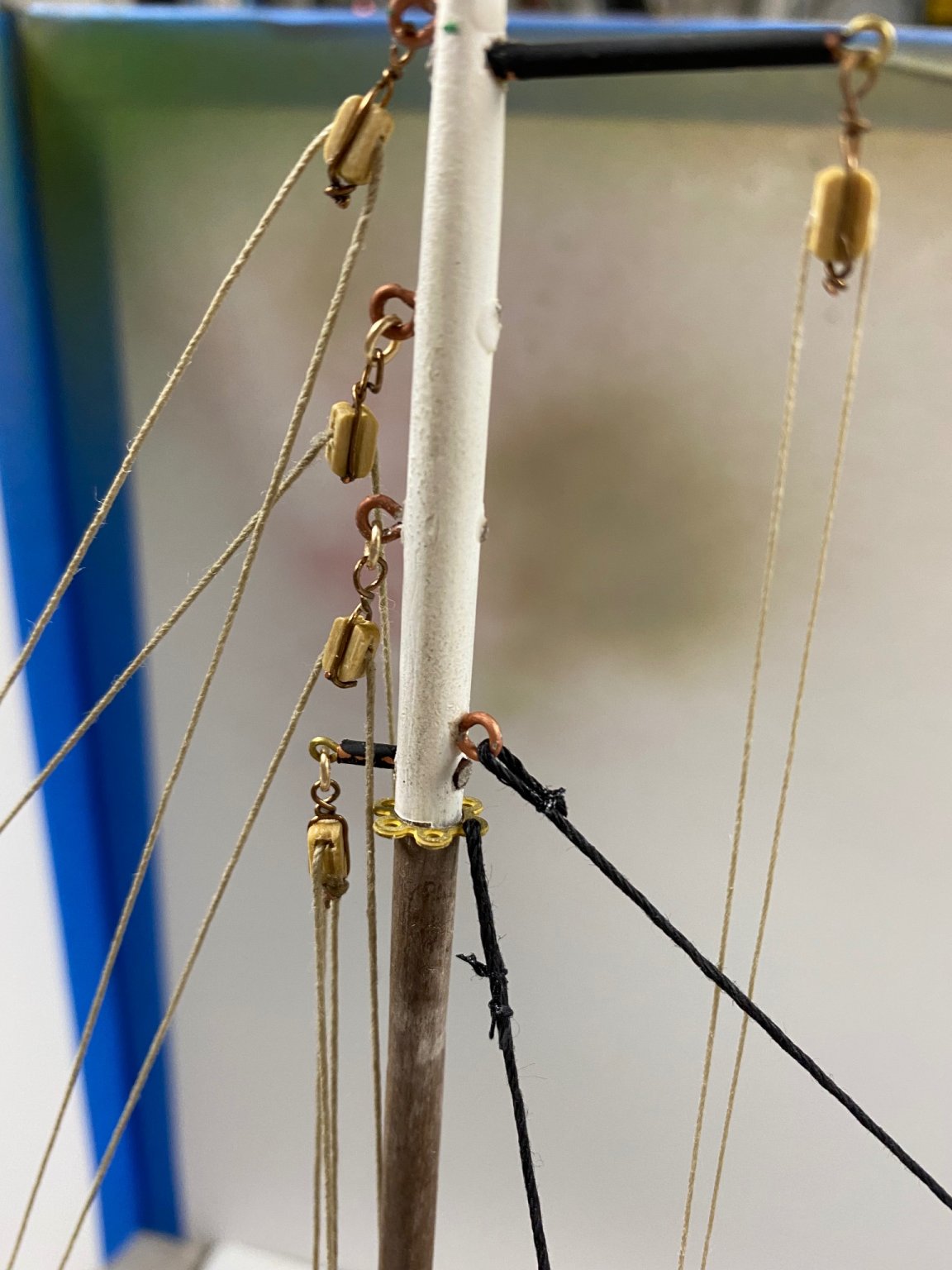
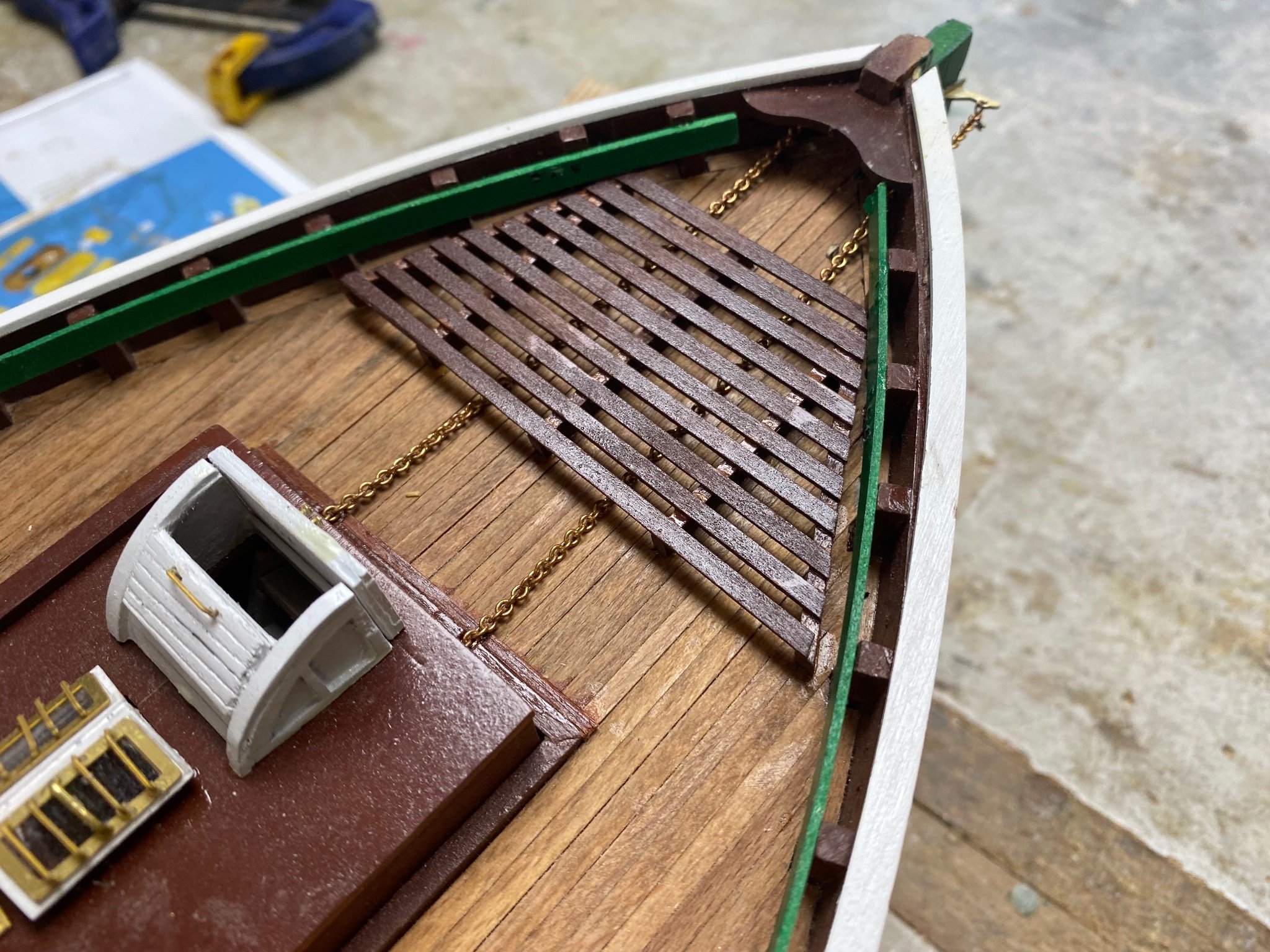
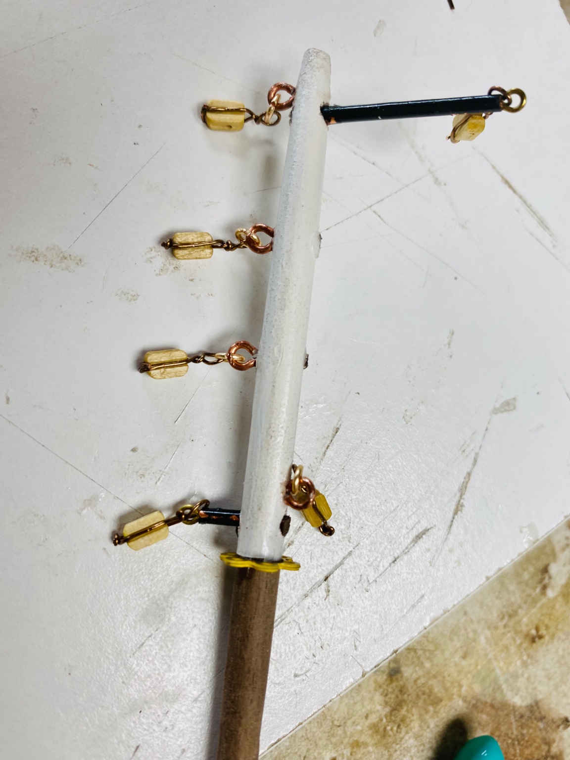
I have been working these past weeks in the rigging of the Fifie. It seems to take forever to rig those double blocks. I stropped the blocks by wrapping a brass wire and making eyes on the ends a needed. Had trouble getting the lines though the little holes even after using sewing needle threaders. in some cases the force necessary to get the the line across was enough to get the tiny wire from its base handle. All that even after I enlarged the holes. This is microscopic work and I praise Everhard (with his Wespe). Anyway I manage to get the rigging you see in the following photos but there is still a lot to be done. But I have to admit that I am enjoying the whole thing. After I finish the rigging I am going to install a sail in the furled position
Still don't know what to do with the hold opening cover boards: to ring or not to ring.


Thanks for watching and your comments are really appreciated
-
-
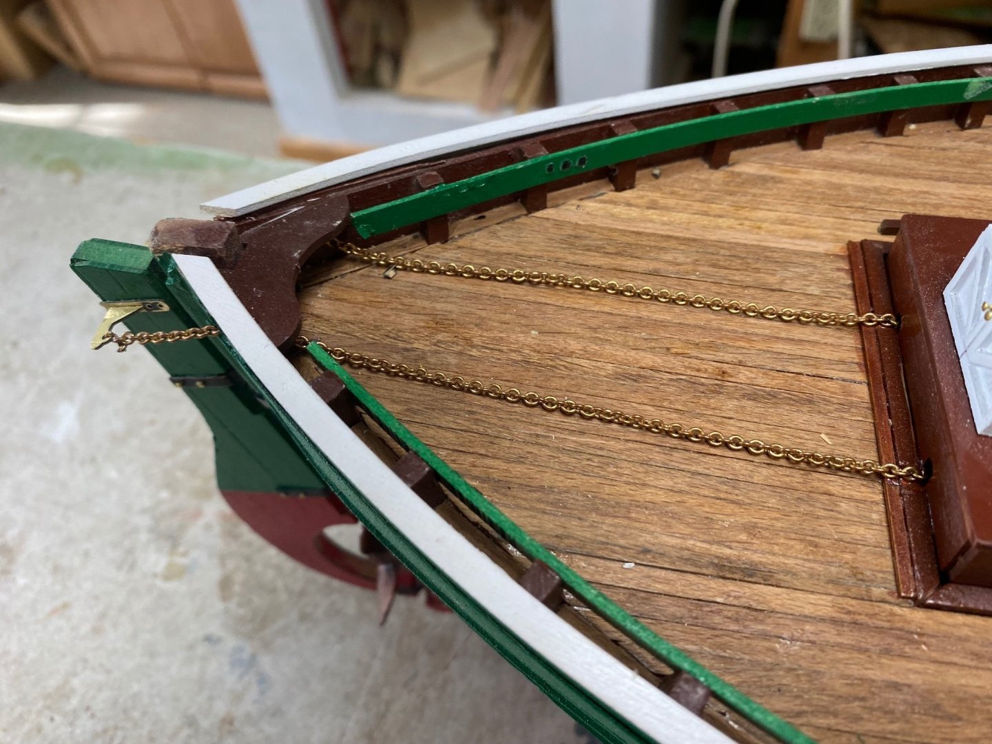
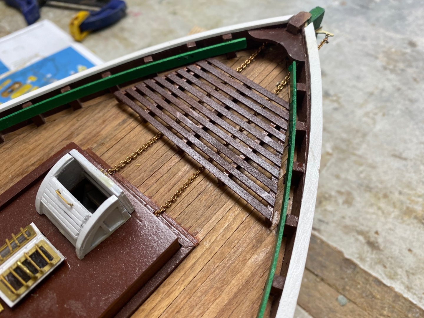
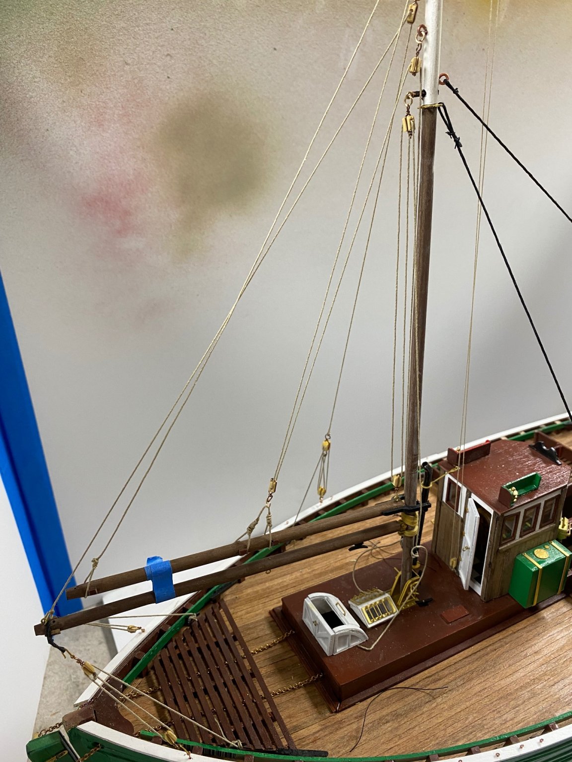
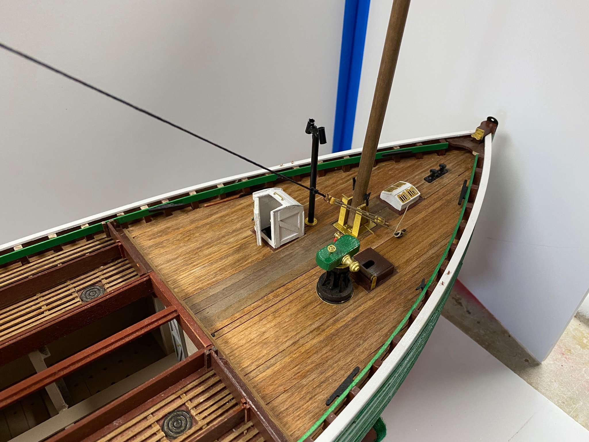
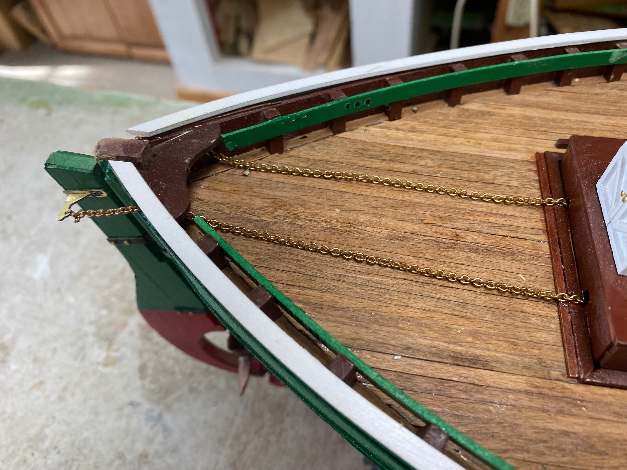
The dog ramp is finished so I am back in the workbench. At this time I am concentrating in completing all of the fixed deck detailing before continuing with the mast and the rigging. First item was to install all the eyebolts and cleats at the deck level. This was done. Then I thought that the chains running to the rudder presented an obstacle to the traffic through the stern.
I built a sort of gangway with leftover wood:
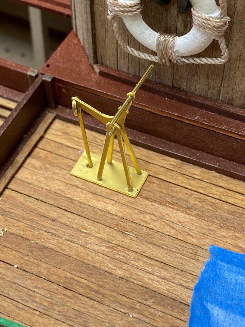
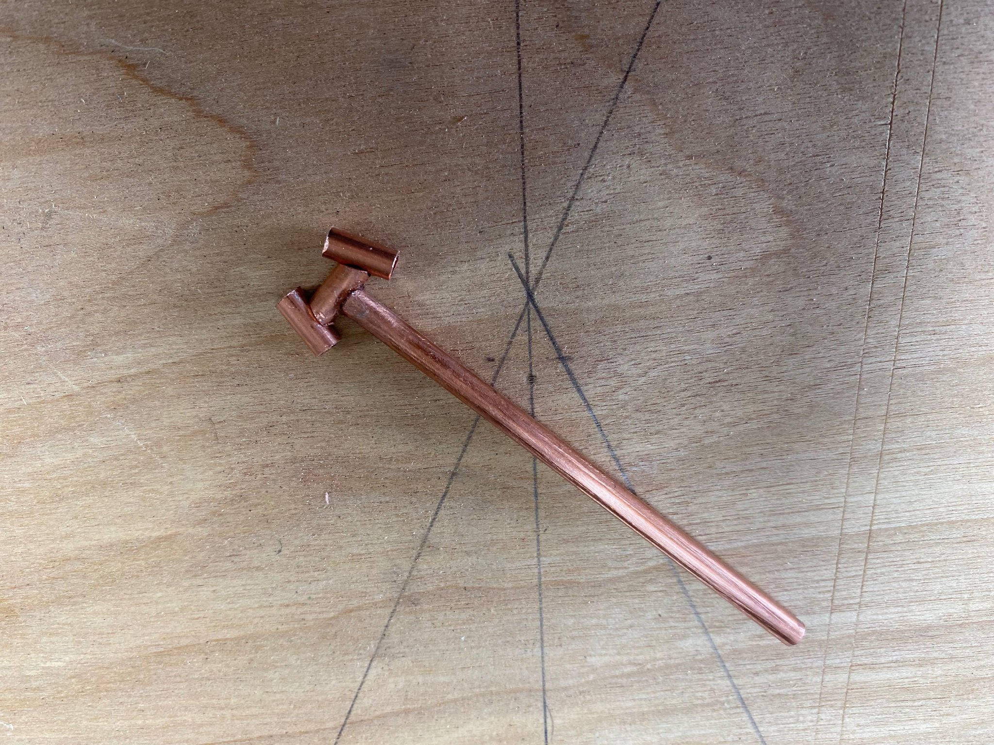
Then I fabricated and installed the bilge pump and the steam winch.
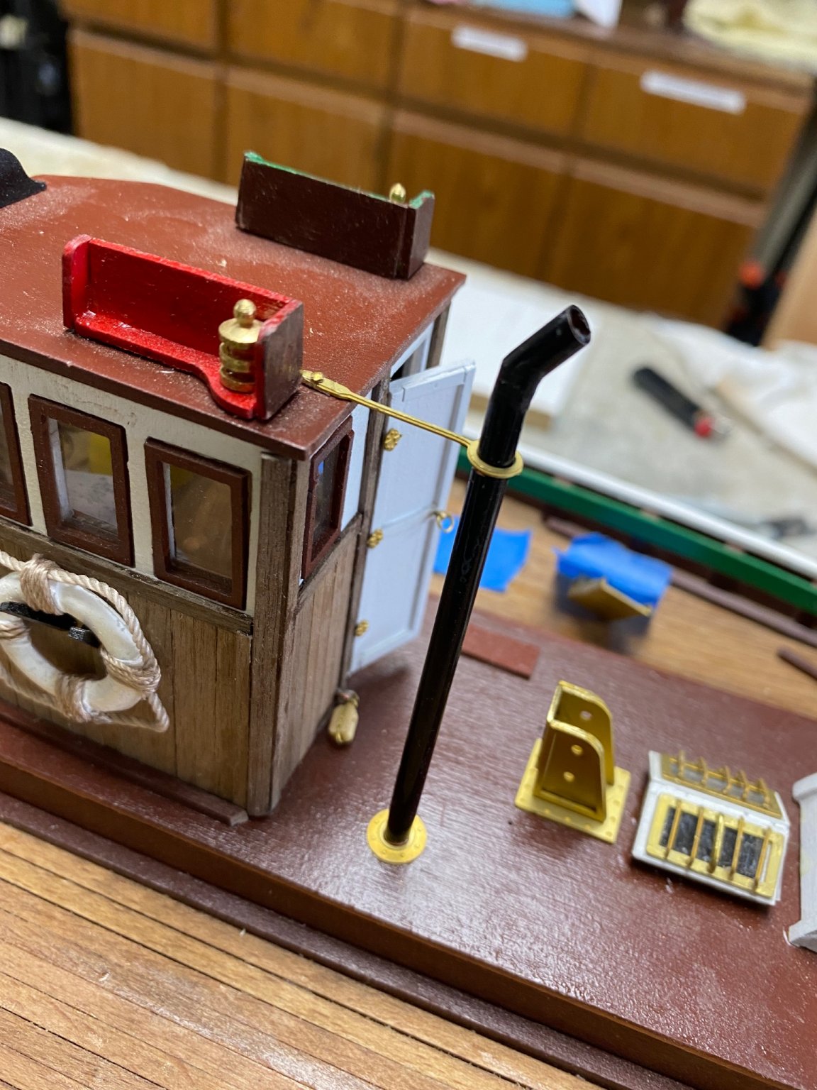
I am still considering adding insulation of the engine exhaust pipe and the free standing steam boiler flue. Would appreciate comments about this. I have seen the actual pictures of the working fifies but it seems to me that the hot pipes present a hazard on deck.
-
Guys, thanks a lot for the likes. I have been busy with other projects. I forgot to tell you that I got multiples hobbies. One of them is to help out some of the old ladies on my building. Thus one has an old dog and a high bed that the dog can’t reach. So I
am building her a ramp for the dog.
-
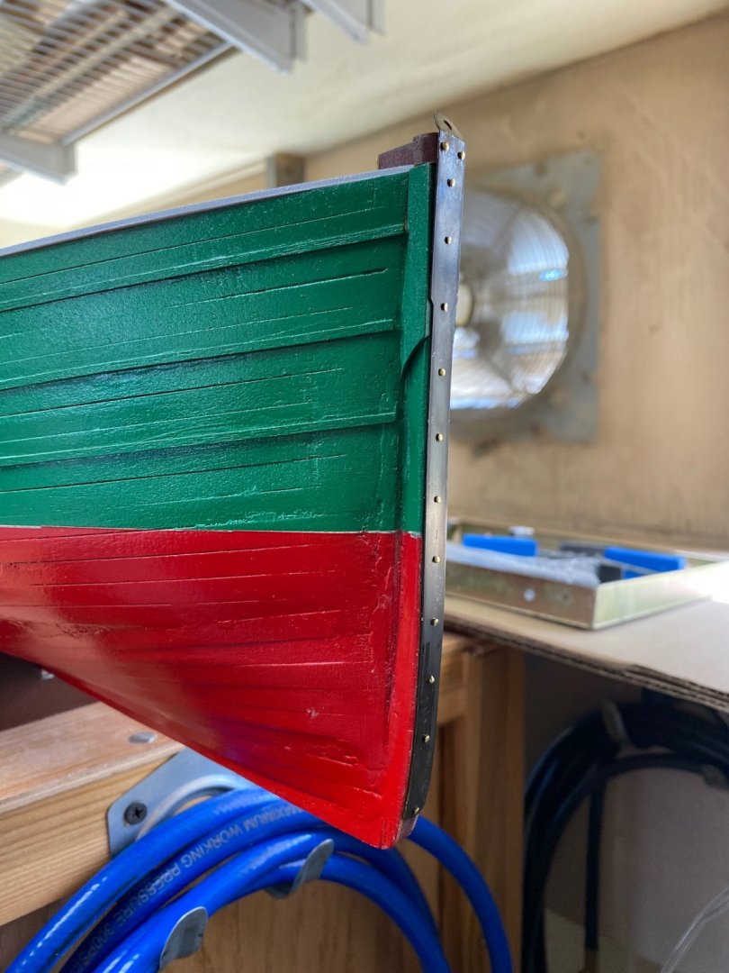
Being a while since my last post but I have been quite busy working on details for my fifie. On my last post I showed you the blackening of the stem water cutter. Following is the part installed.
Next I dry fitted the aft mast and the engine exhaust pipe. I have been considering insulating the exhaust pipe but it looks good to me as a plain copper pipe.
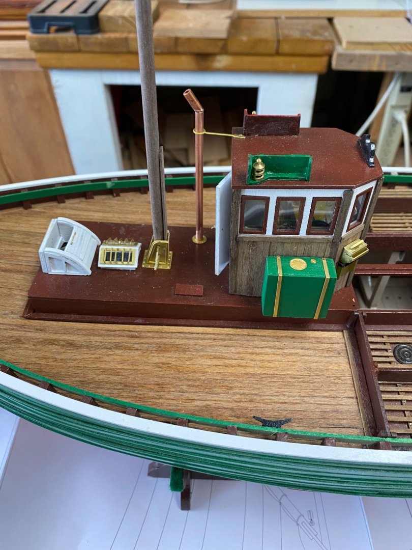
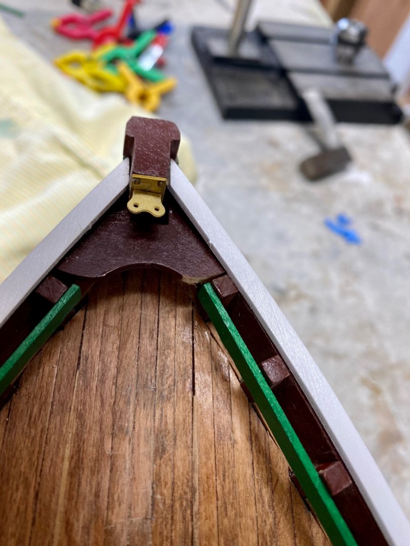
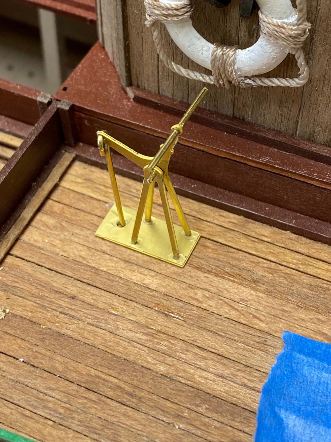
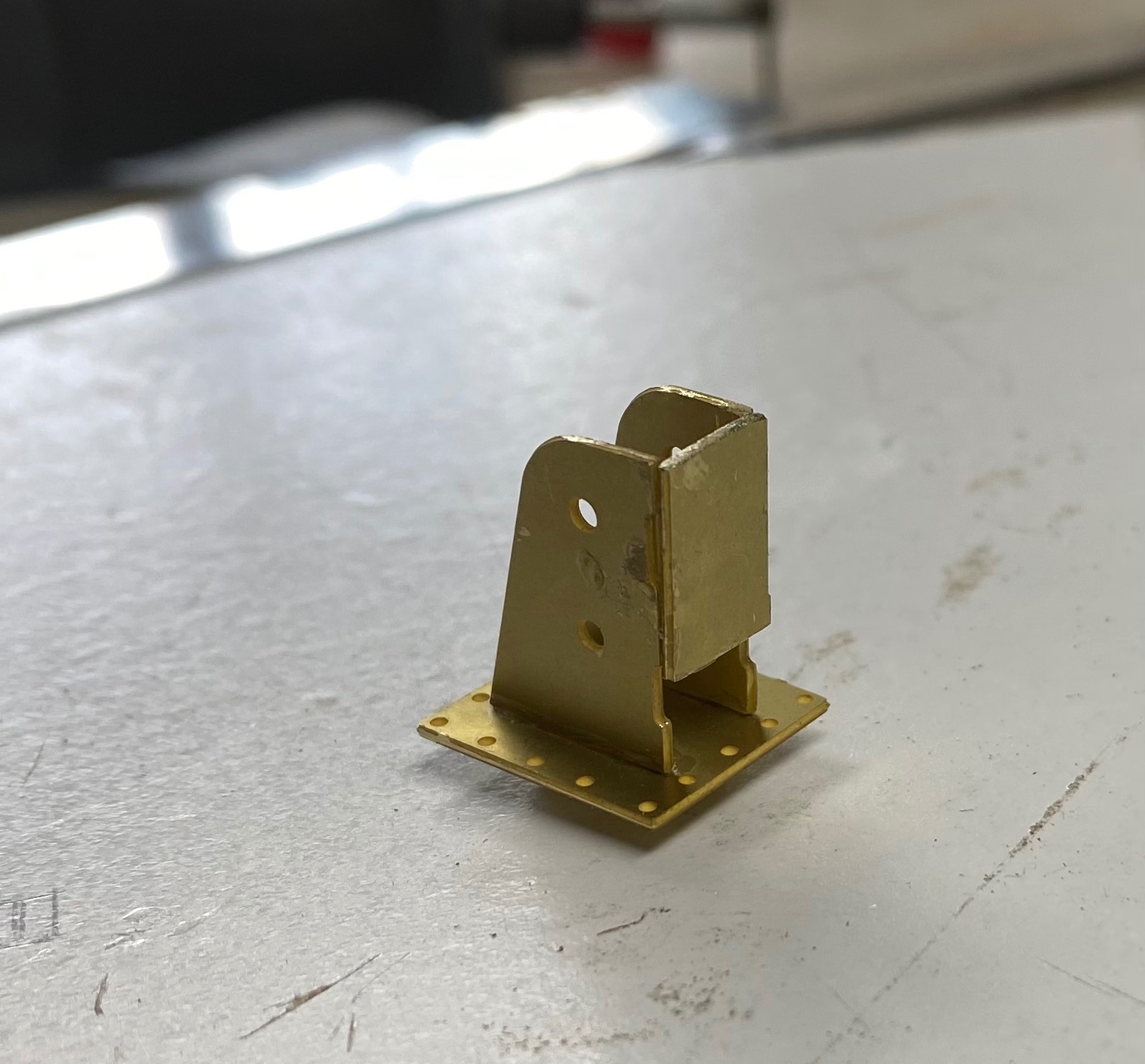
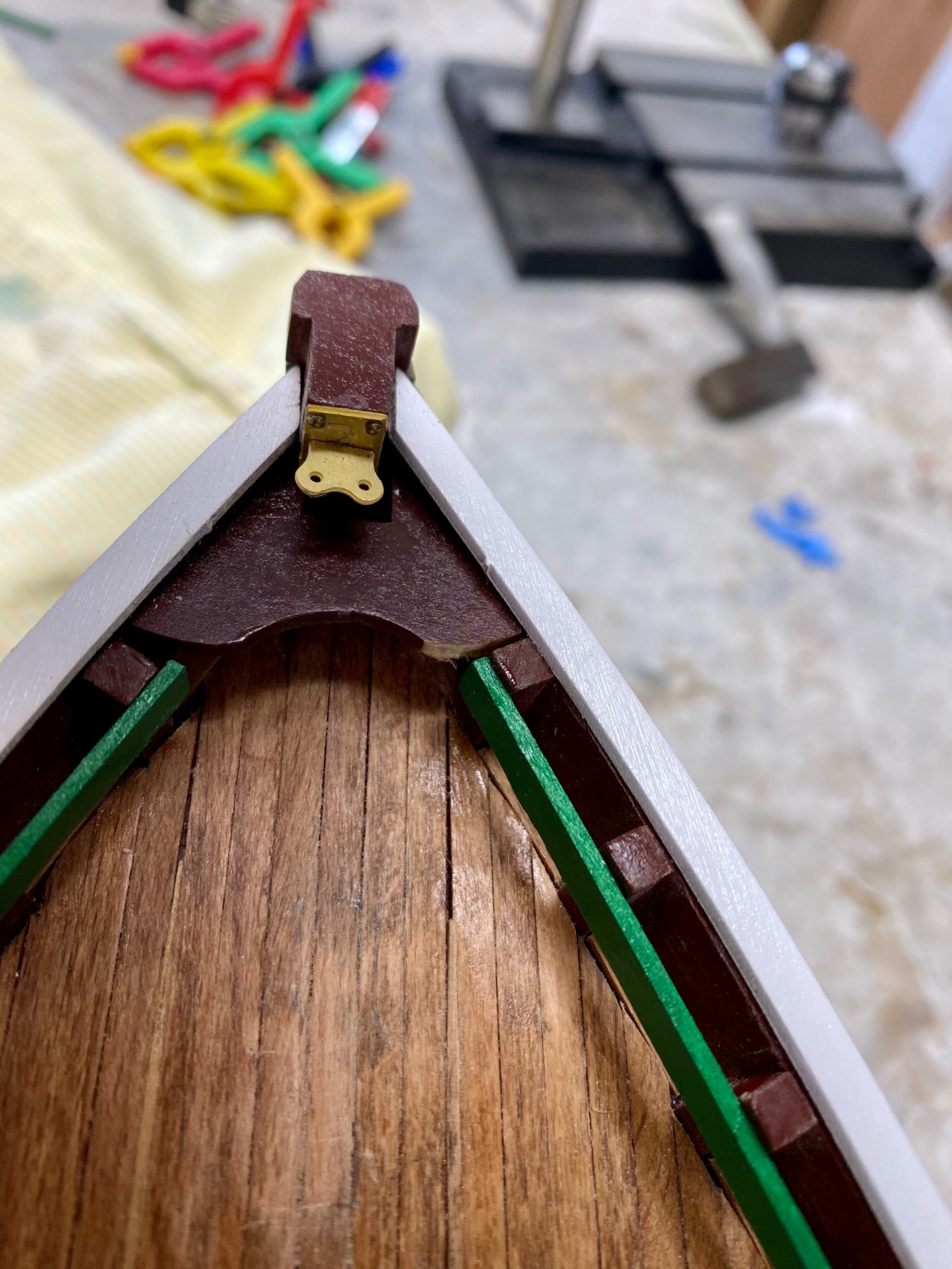
Fabricated and dry fitted the forward mast tabernacle.

After this, I started what I considered microscopic work: fabricating the pieces for the after mast.
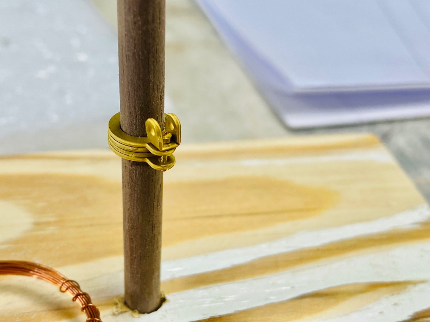
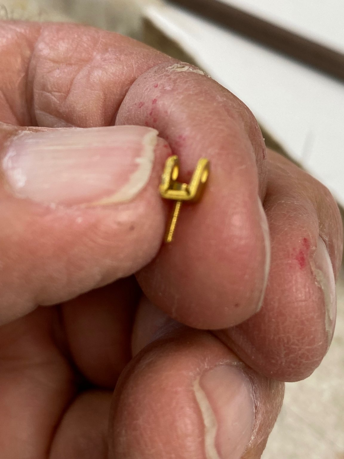
Then I ran into a problem. My mast tapering did not match size of the holes in the provided brass hooks.
Back to the drawing board....
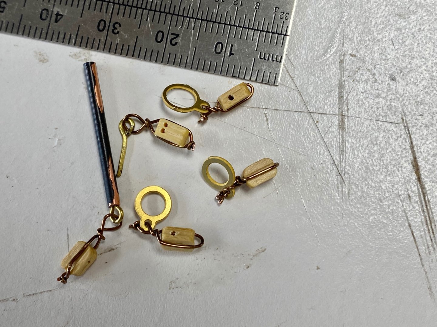
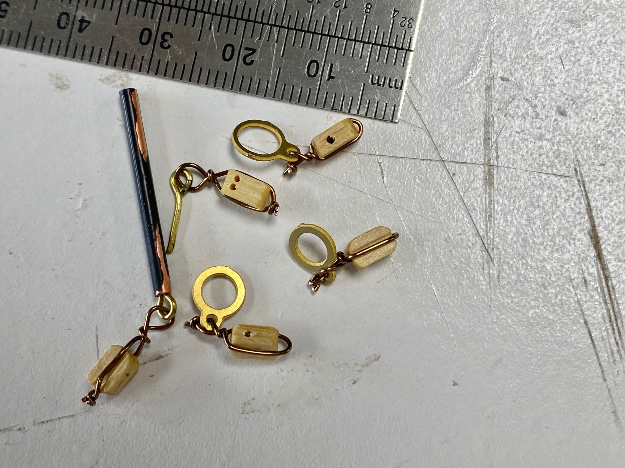
Since the purpose of the hook was to a provide a place for the eye I decided to fabricate the eyebolts and drill the mast for installation.

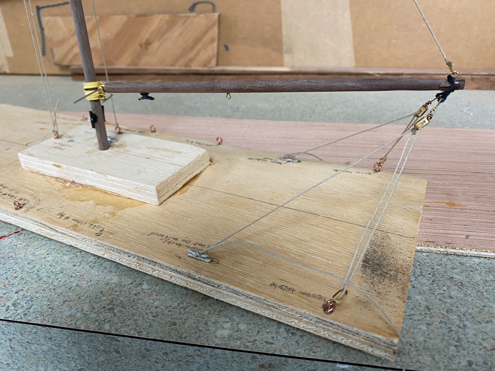
I made a simile of the deck on a piece of wood, installed the after mast, and proceed install the beginning of the standing rigging. This will make the rigging easier (for me) to place it in the model once I have completed the rest of the deck details and fixed some of the boo-boos.
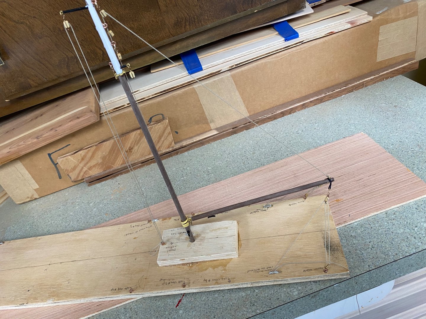
Keep watching, more is coming.

- Rik Thistle, yvesvidal, egkb and 1 other
-
4
-
Eye candy PGL. How about another one?
-
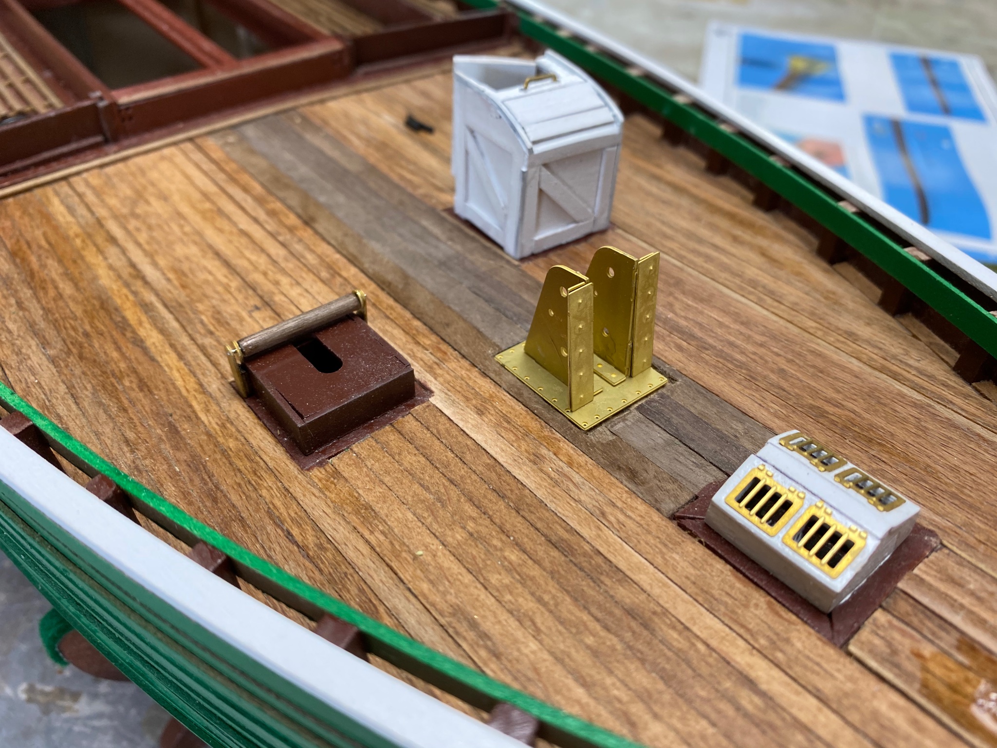
I am trying to get all the miscellaneous work done before getting into the serious business of rigging the ship.
While working on the rudder, I drilled the holes for the operating chains and , would you guess? My shaky hand slipped . But the magic MiliPutty came to rescue and all thats left is to retouch the paint. As I mentioned before this boat belongs to a very poor scotsman.
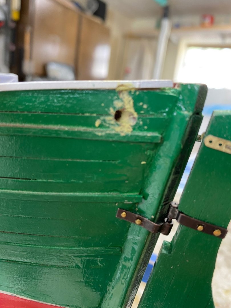
While working on the aft mast tabernacle the front EB piece disappeared, like by magic, now here then is gone. I went in my fours and searched all over the carpet , the workbench, my pants, et al, to no luck. then I just cut a piece from the brass etched leftover and this is the result

All I need now is to drill a hole for the cleat.
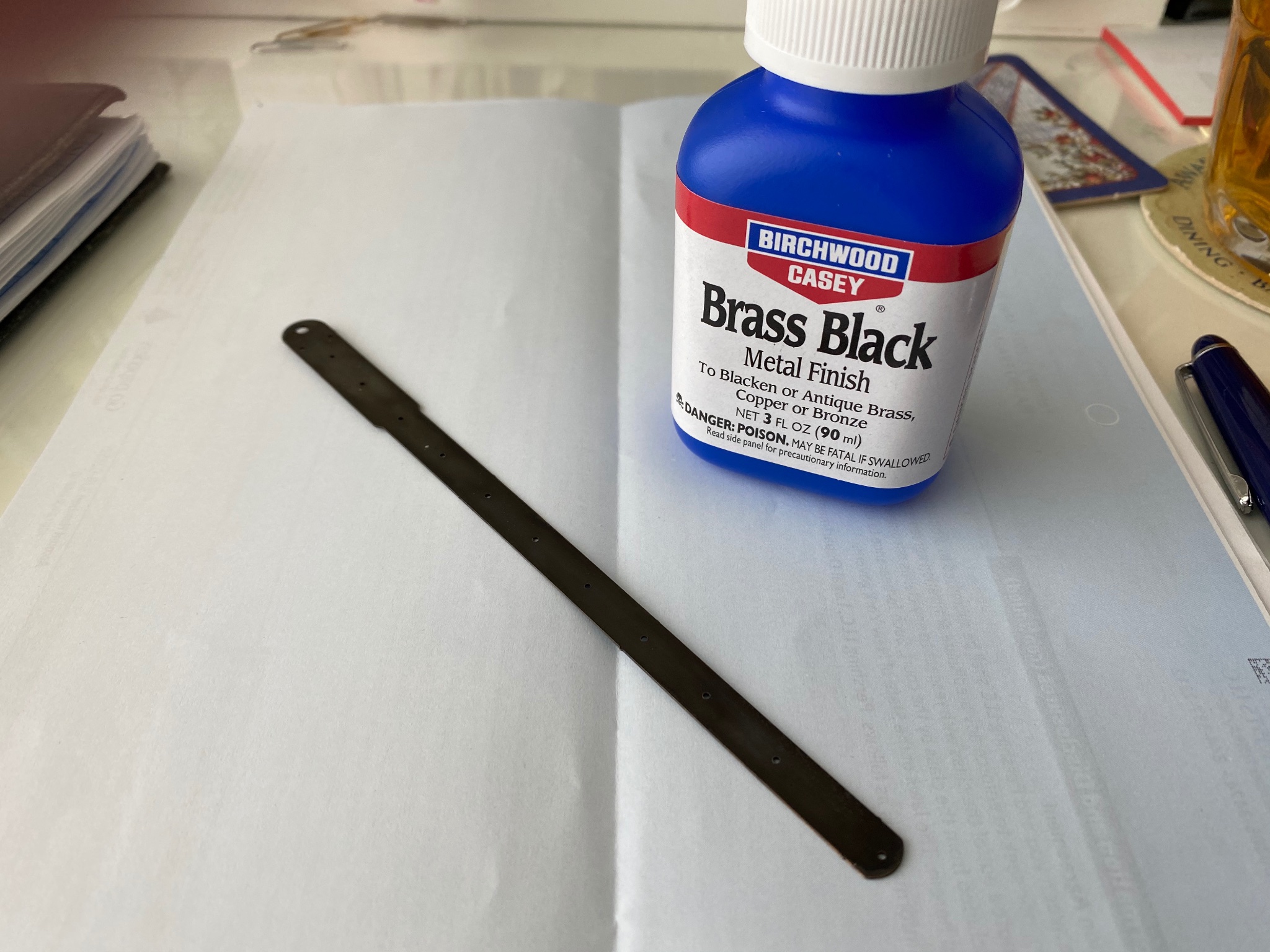
Then I worked on the stem brass piece. I was going to paint it black but decided to try and use the blackening system and I seen you all use. I bought the Birchwood Black Metal Finish. In my first try the color was not even and I blamed it both on the slick surface of the brass and the lack of cleanliness of the piece. I sanded the piece with 400 grit and wearing rubber gloves wiped it with alcohol and this is the result

Next , I am going to work on the forward mast tabernacle and the fabrication of the masts.
- goetzi73, yvesvidal, Rik Thistle and 4 others
-
7
-
-
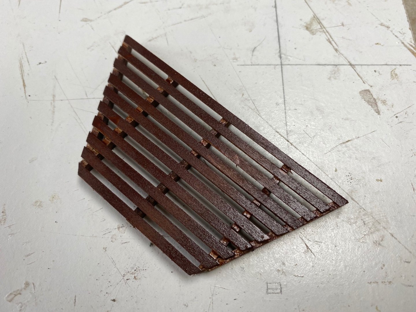
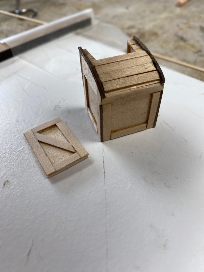
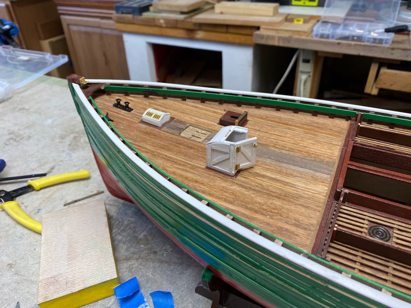
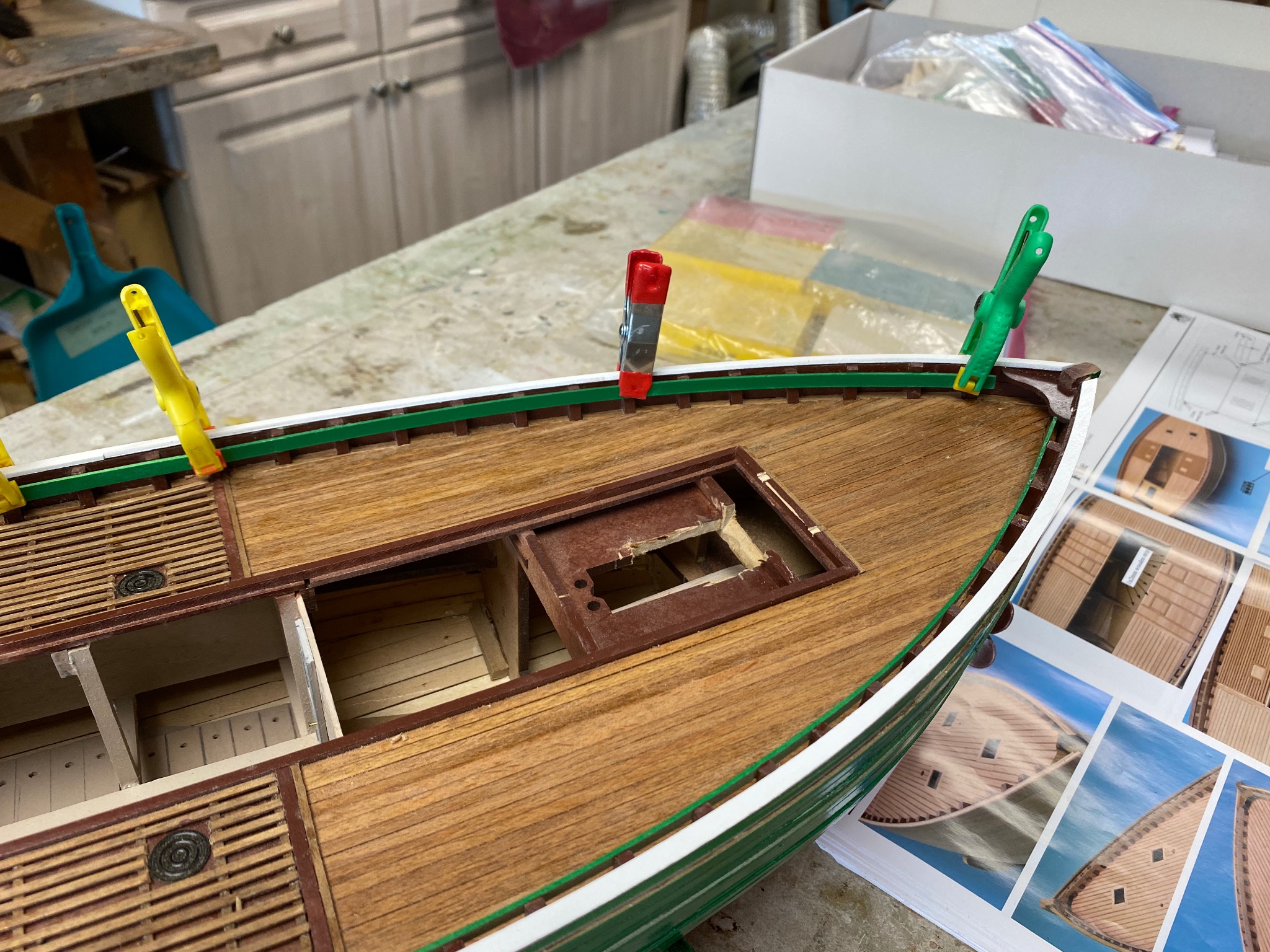
Doing a little research I found that the inside strake at the top of the gunnel is called "quickwork". So, I finished the "quickwork and installed the large cleats. Proceeded to fabricate and install the boards in the fish pound. I also fabricated a small addition to the stem in order to install the etched piece with the holes for the rigging.

I have been looking at the size of the companionways and had figured that a big strong scot fisherman will have a hard time sneaking in to get below. I had made the aft a companionway, leading to the engine room, a little larger and decided that the fwd companionway, leading to the leading to the crews area, would also be larger. Following is my concept of this reviosed design.
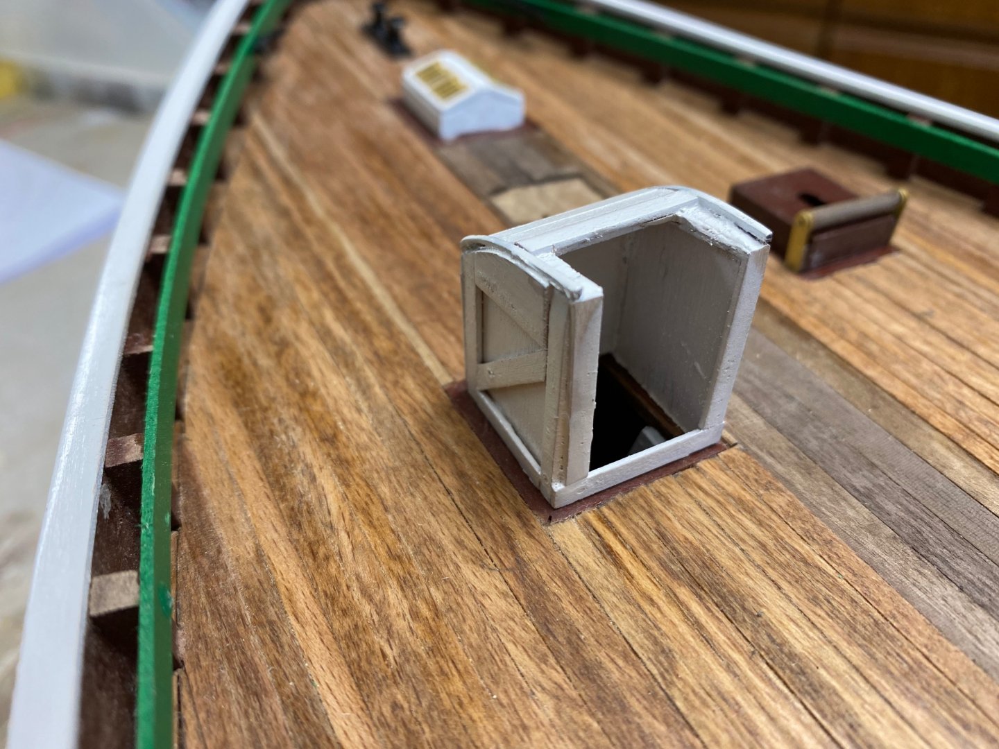
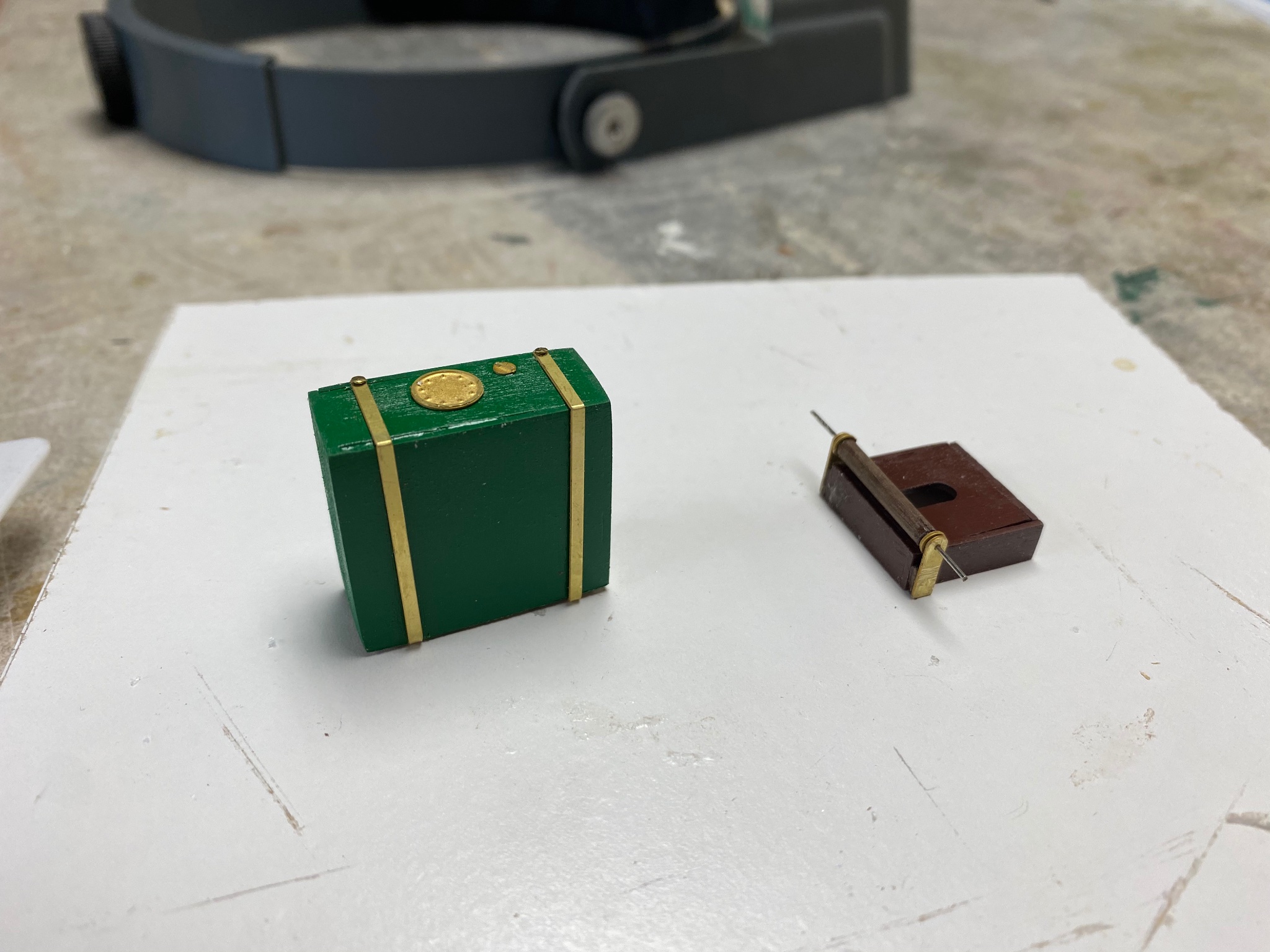
There were no etched parts for the hinges and door knobs so, I decided to try and make them. It was a little frustrating as the size is so small that even my pincers were too big and my hands could hardly handle the pieces. I used brass shim plate and cut brass nails. The large nail became the door knob.
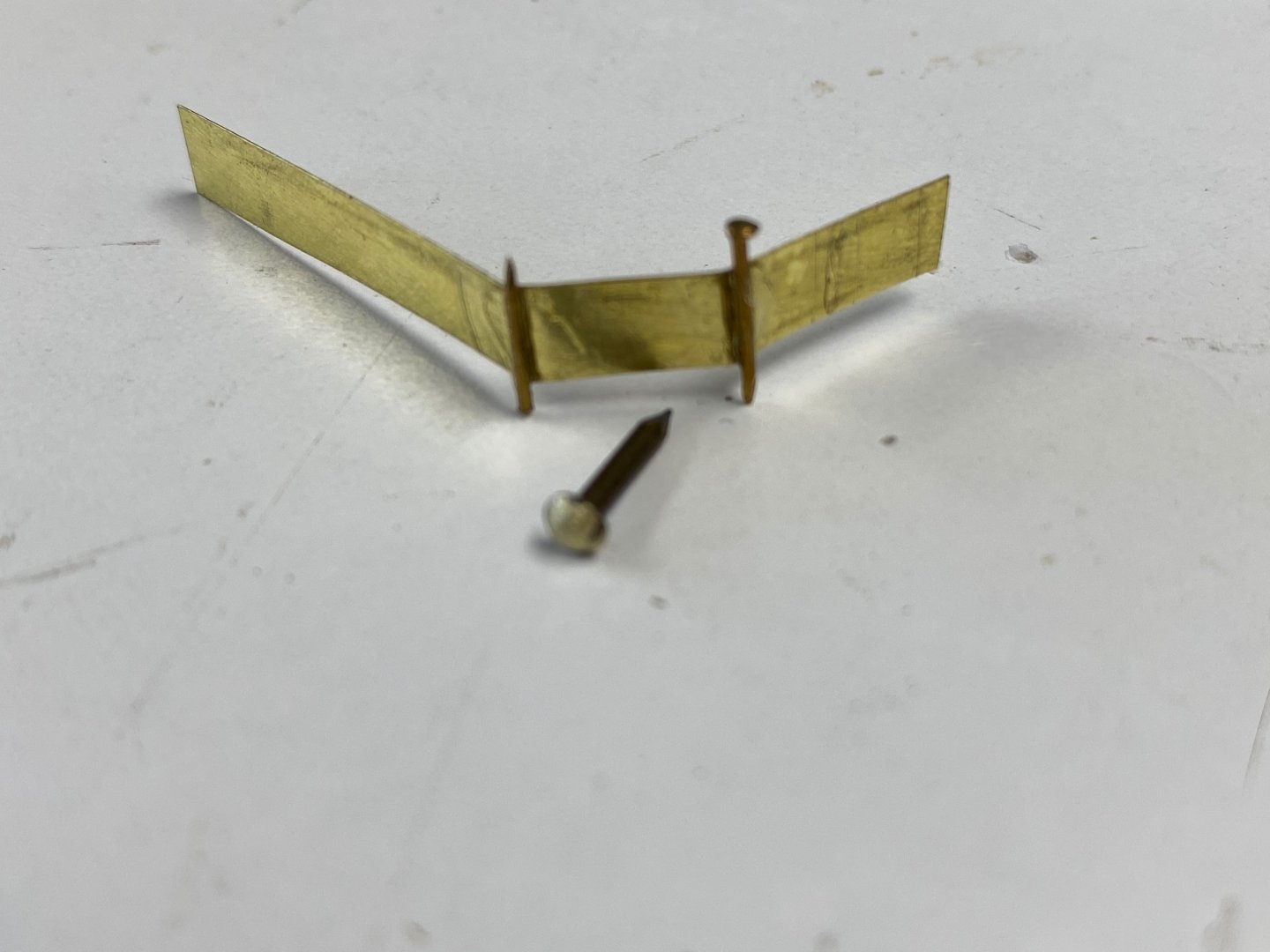
And I forgot to take a picture of the finished product. The results were installed in my new fwd companionway.
I started to notice a little sloppiness in my painted pieces but, as I said before, I am not good at paint. And I figure these boats belonged to poor people that were more busy trying to make a living than having neatly finished boats.
To continue, I completed the installation of the propeller and even installed a lock pin on the hub. Then I proceed to install the rudder. It was actually easier that I thought it would. I had already installed the pintles in the rudder and had located the lower gudgeon. That made it easier to line up the other gudgeons. I had a little trouble because my rabbet line was closer to the end of the stern post. Had to do a little bending of the gudgeon flanges but, the result was not too bad. Sorry, I forgot to take a picture of the finished job but you may be able to see it in the general views that follows.

All in all, I am having a ball building this fifie. Can hardly wait to finish it to get on with my next project: the Brazilian customs gunboat (1907) Amapá. This will be scratch built form plans I obtained back in 1996 while I was living in the Netherlands.
-
-
-
VTH, I am also following you. Once I finish Fifie I am going to do the NRG half hull to sharpen my planking knowledge. I love doing the small details and to improvise from common objects. This scales, 1/32 and 1/24, are perfect to make semi-real miniatures.If you want to see perfection, watch Wefalk. Happy having you as a follower.
-
-
Last night I spent a couple of hours following Wefalk's (Everhard?) build. He is scratch building the SMS Wespe, Imperial Navy armored cruiser (1876) in N scale (1/160). Amazing craftsmanship where 1 mm is a large dimension. He is fabricating every fitting and part of this boat using watchmakers tools. I learned a lot about preparation and the perseverance required. .
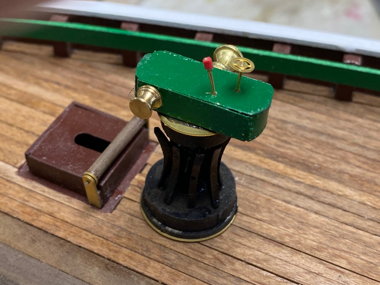
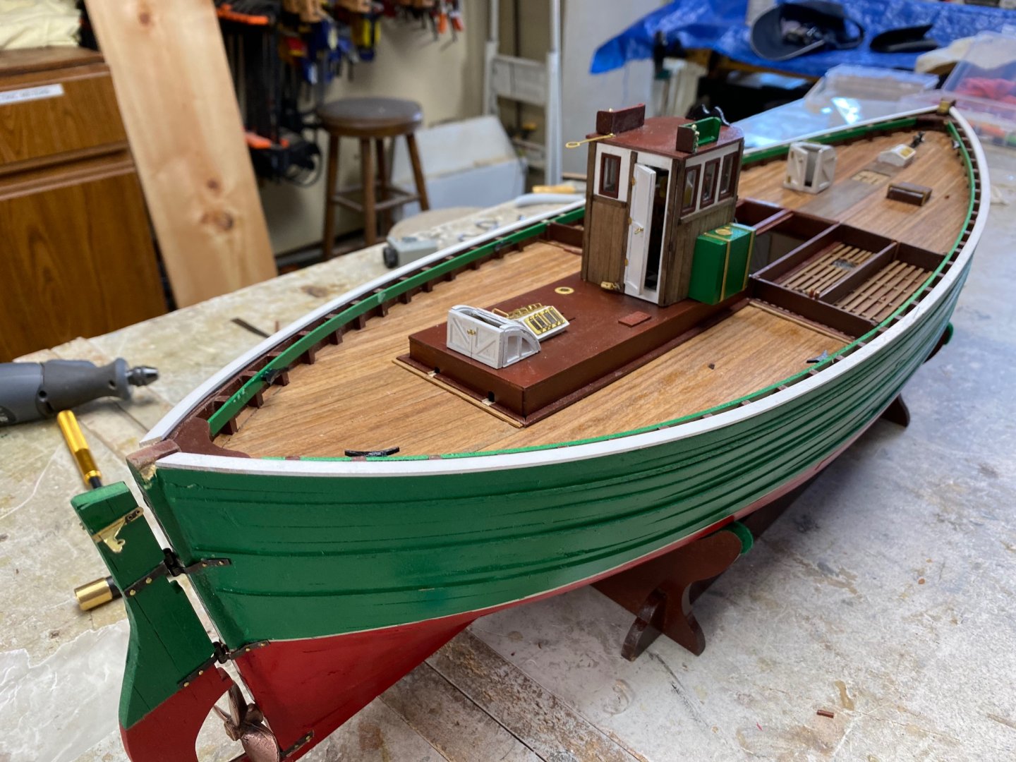
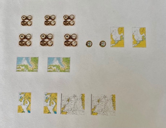
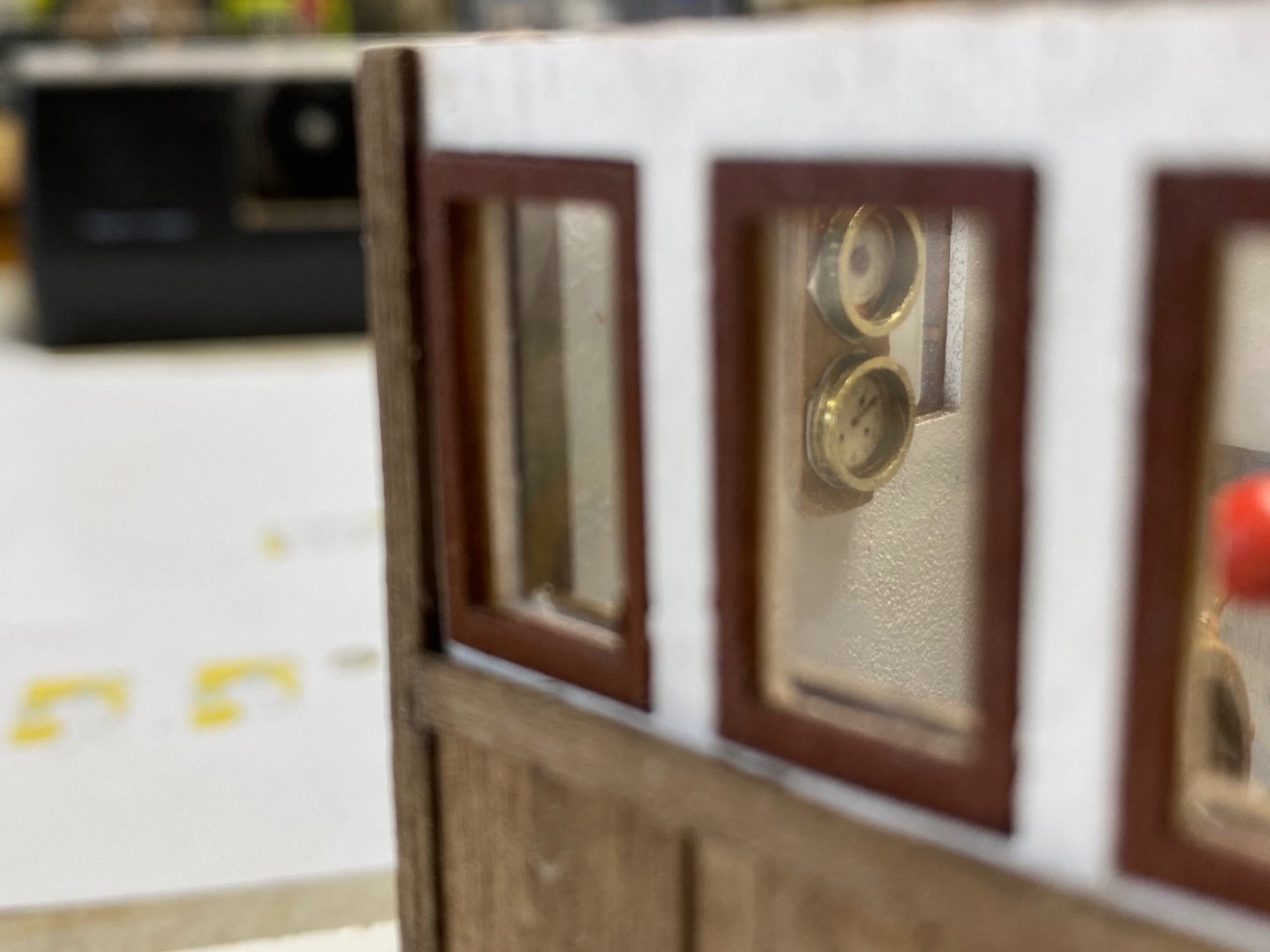
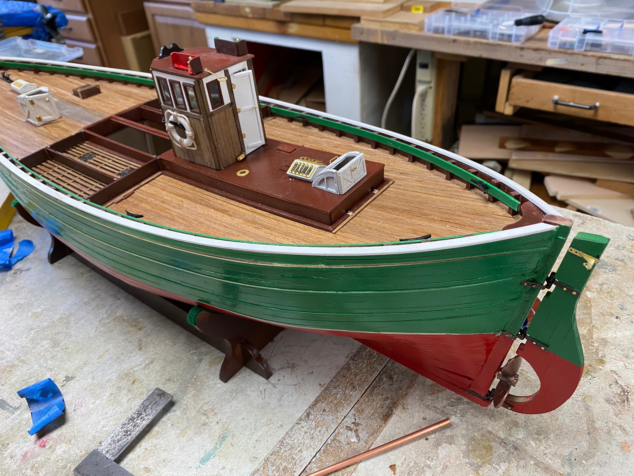
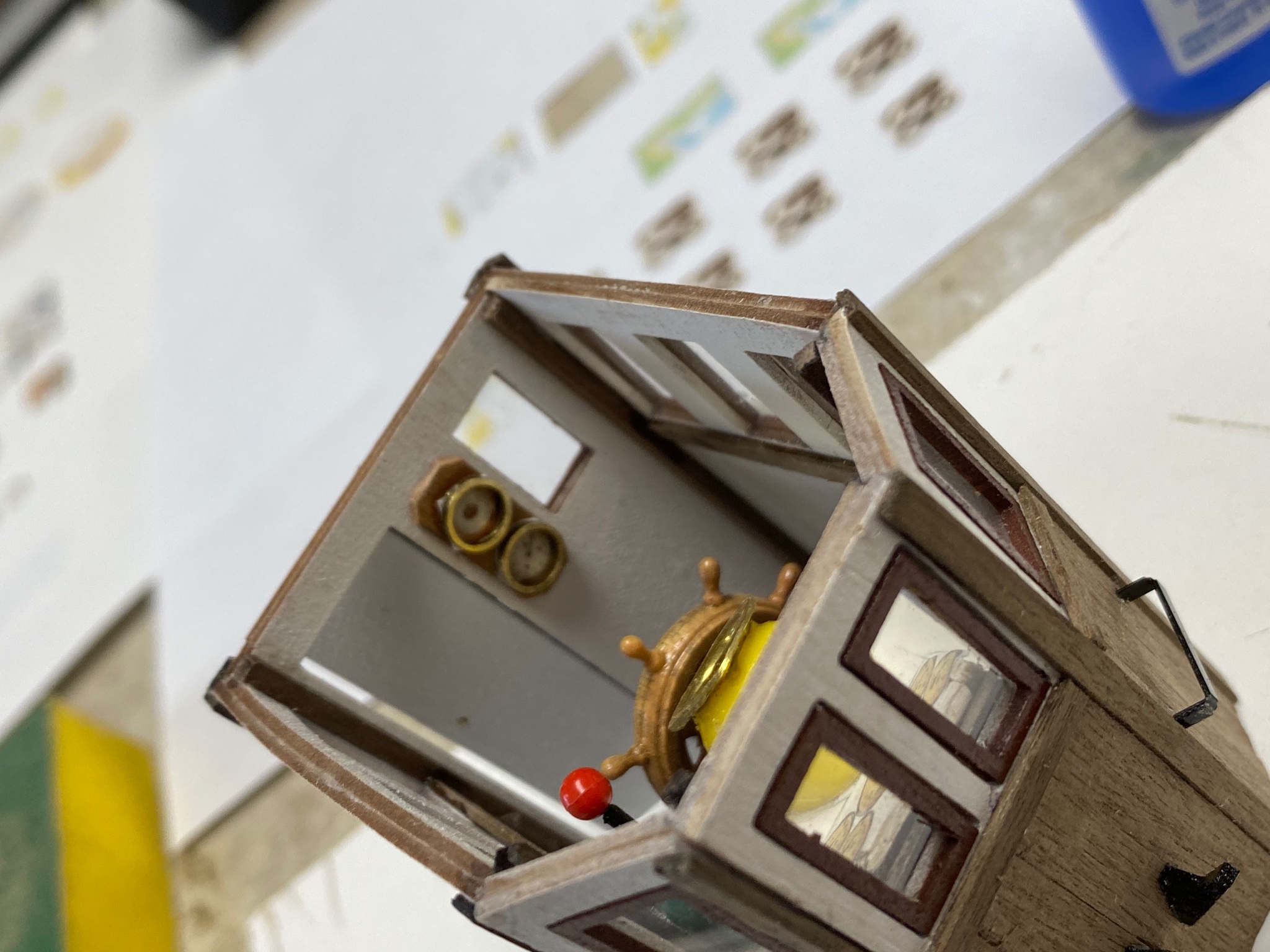
I am again taking a break from the ship's hull and doing some more detailing. I love details. Figuring out how to fabricate them is the pleasures of this hobby. I have not, and probably will never, manage to to do museum class miniature work. I am not a perfectionist and I don't hesitate to using available materials. That said, I am trying to "super detail" my pilot house. In a previous post I described how I fabricated the engine instrument panel but I still wanted a little more. I found a lot of scale brass mast rings in a box and figured that they will make great brass bezels for the instrument. Then I decided that, going on to the cold waters of the north sea, the fisherman will have to navigate using a compass (already furnished), a chart and a clock. Also, in those waters, weather changes dramatically and a barometer may be necessary. Therefore I decided to provide said necessities.
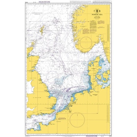
First we do the charts. I googled the fishing area charts and found several admiralty charts of the upper NE sections of Scotland including the northern isles. I downloaded some of the pictures and printed them reducing it to scale size.
Folded it down and set it on top of the instrument cabinet. Note: The pilot house is very small and should have had some space for a table.
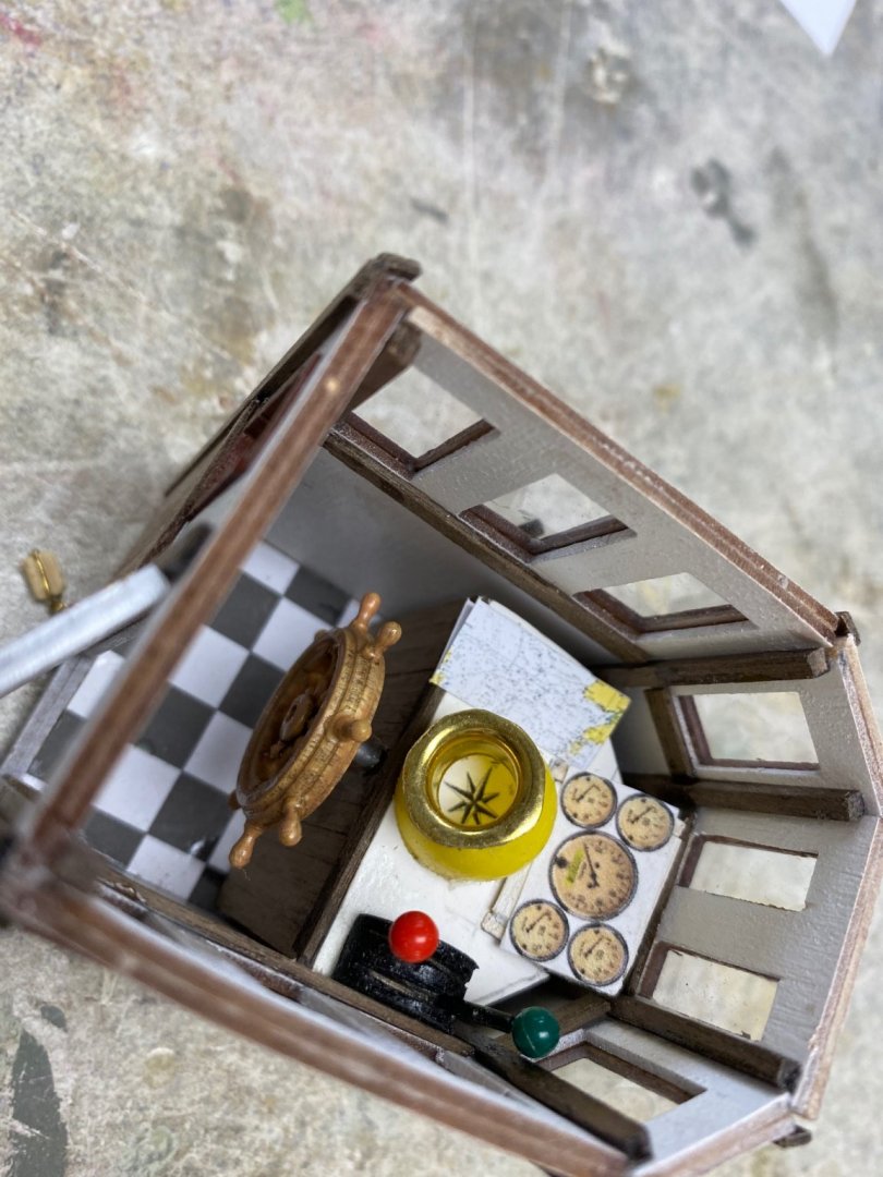
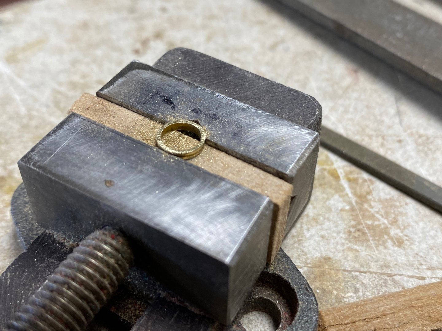
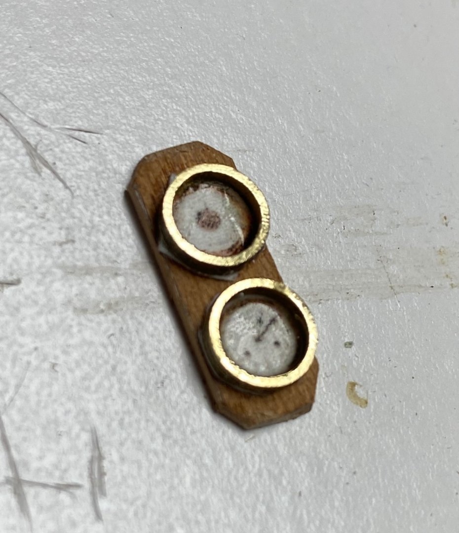
Then, I turned my attention to the gauges. In my case a 6" gauge will be reduced to 5 mm. The mast rings I found were of the same size (5mm) but looked too thick (2mm). So I had to shave at least 1mm off the ring. I made a parallel out of leftover wood and set the ring on my milling vise.
My reduced instrumentation was printed in glossy photo paper. The required printed gauge was cut, the bezels added and a wood base was cut from a slice of mahogany and installed in the only available wall space.

And it can even be seen from the side windows.
- JpR62, Rik Thistle, yvesvidal and 4 others
-
7
-


Flower-Class Corvette by Yves Vidal - FINISHED - 1/48 - Bensworx Virtual Kit - 3D printed
in - Kit build logs for subjects built from 1901 - Present Day
Posted
Going back to Egilman. It seems to me that the 3D is nothing more than a parts making machine instead relying on a kit maker or in your construction abilities. Then modeling becomes , like Roka says, a computer ability test. But you will have to to still assemble the parts and this is really what we do.
So I am OK with both alternatives but I don't think I can handle the computer side so I will continue buying kits or making my parts the old way.