


modeller_masa
-
Posts
838 -
Joined
-
Last visited
Content Type
Profiles
Forums
Gallery
Events
Posts posted by modeller_masa
-
-
Thank you for the detailed explanations, Andy. The launch procedure is more complex than I thought. It is really interesting that dock workers remove stable wooden logs and insert slipways one by one, like a jenga game. Also, the method of draining water using terrain is really clever.
Because of the special equipment, such as slipways and launch cradles, I'm not ready to build launching ceremony dioramas. I'll keep it on my bucket list and collect more data for future building... Thanks so much!
- mtaylor, druxey, realworkingsailor and 1 other
-
 4
4
-
-
I have a question about 18th century shipyard docks. According to the video's beginning, the shipyard's bottom is flat and wide. The keel is on the wooden logs like a railway. I'm curious how did 18th century sailing ships, like the HMS Alert, get balance when she was launched.

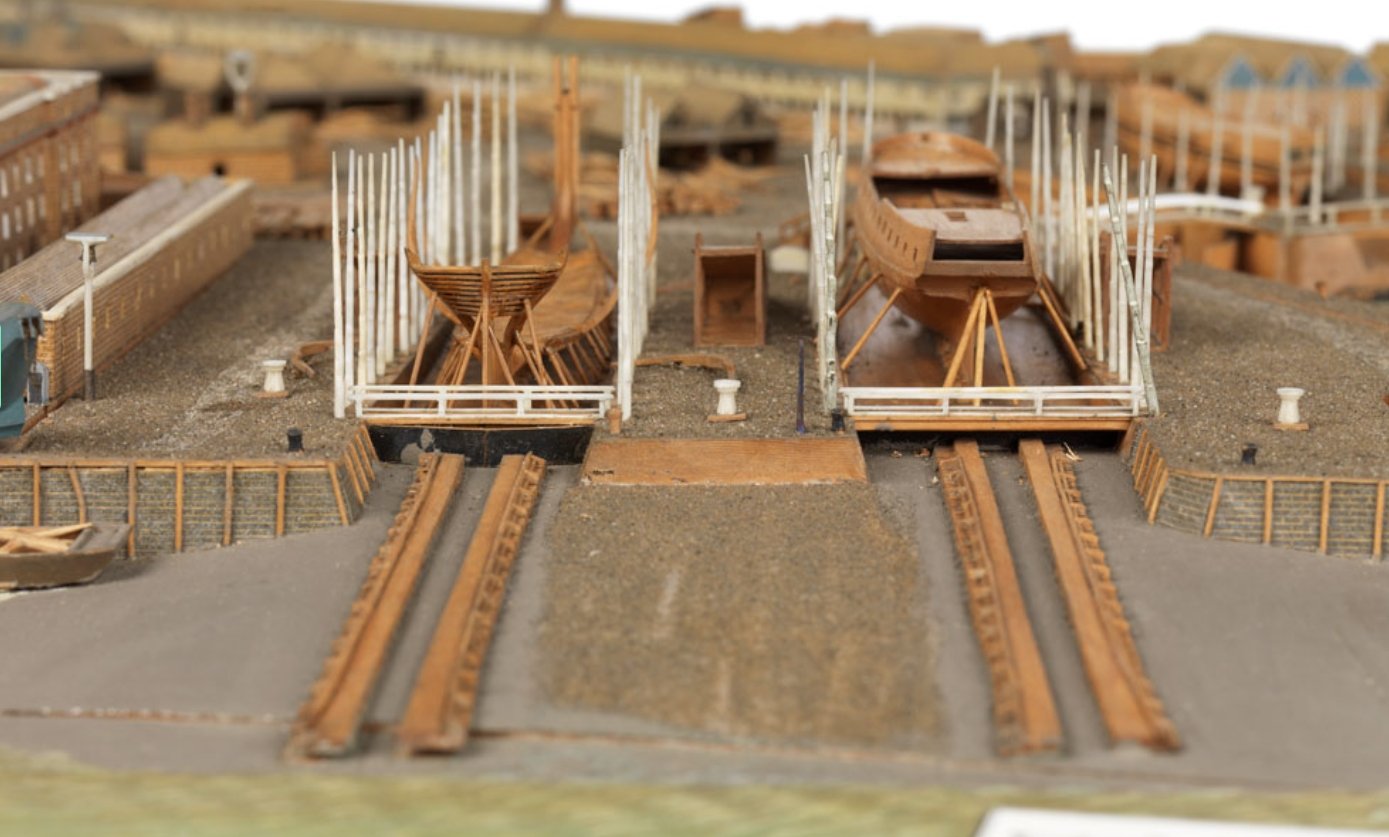
( Source : https://www.rmg.co.uk/collections/objects/rmgc-object-68861 )
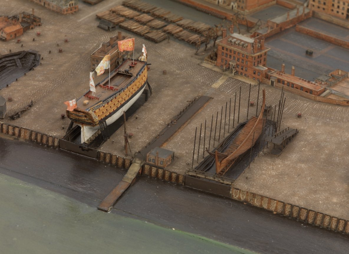
I researched some contemporary dry dock dioramas, and they shows several characteristics of dry docks in 18th century.
1) Some dry docks had water gates, so the gates are opened when the ships were ready. It is identical to modern shipyard.
2) Some dry docks had sloped bottom. As a result, the ships were on uneven ground.
3) The outside of the dry docks were connected to 'railway'. It is really amazing how the ships were safely balanced when she was moving on the wooden logs and railway before ceremonial launching day.
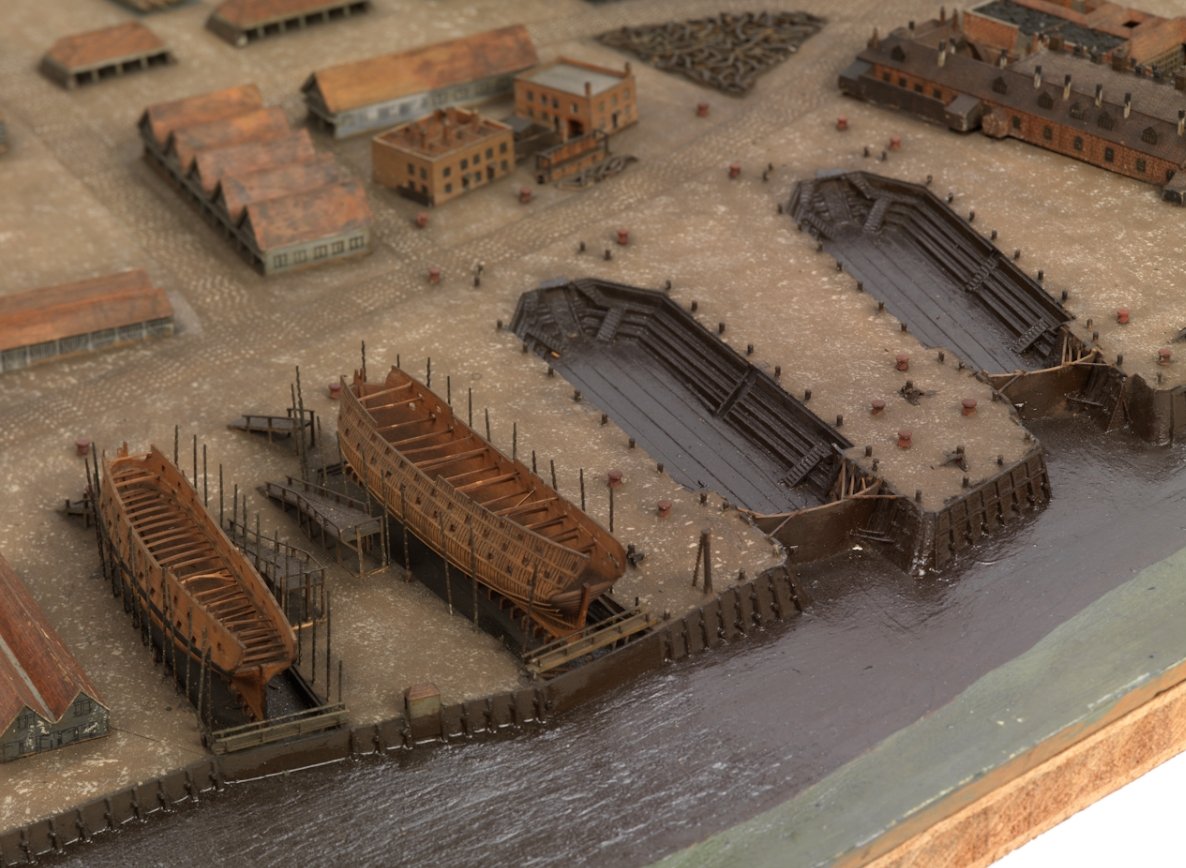
( Source : https://www.rmg.co.uk/collections/objects/rmgc-object-68110 )
4) In the Chatham dockyard diorama, all the dry docks had flat and solid wooden bottoms. It is very similar to the modern shipyards.
It looks like magic that completed ships on the wooden log rails were smoothly launched without any rollover accidents.
Summary
- In the 18th century, were all dry docks for large sailing ships flat?
- Were the wooden logs sufficient to launch the big sailing ships without water? Did workers replace the wooden logs with rail before launching?
- Why didn't dockyard place completed wooden rails when she was laid down?
- Were there any launching accidents in the century? I remember the HMS Formidable's case.
I think this question is a big chunk to digest at once. Could you recommend any reference books or guides to explain launching the big sailing ships?
-
Thank you for your feedback, Tomek.
I hope to see the build logs or finished pictures on the Polish card board community sites. They'll be a good reference for building the next card board model kit.
Thank you again for watching my project, and see you again when I send a new order.
-
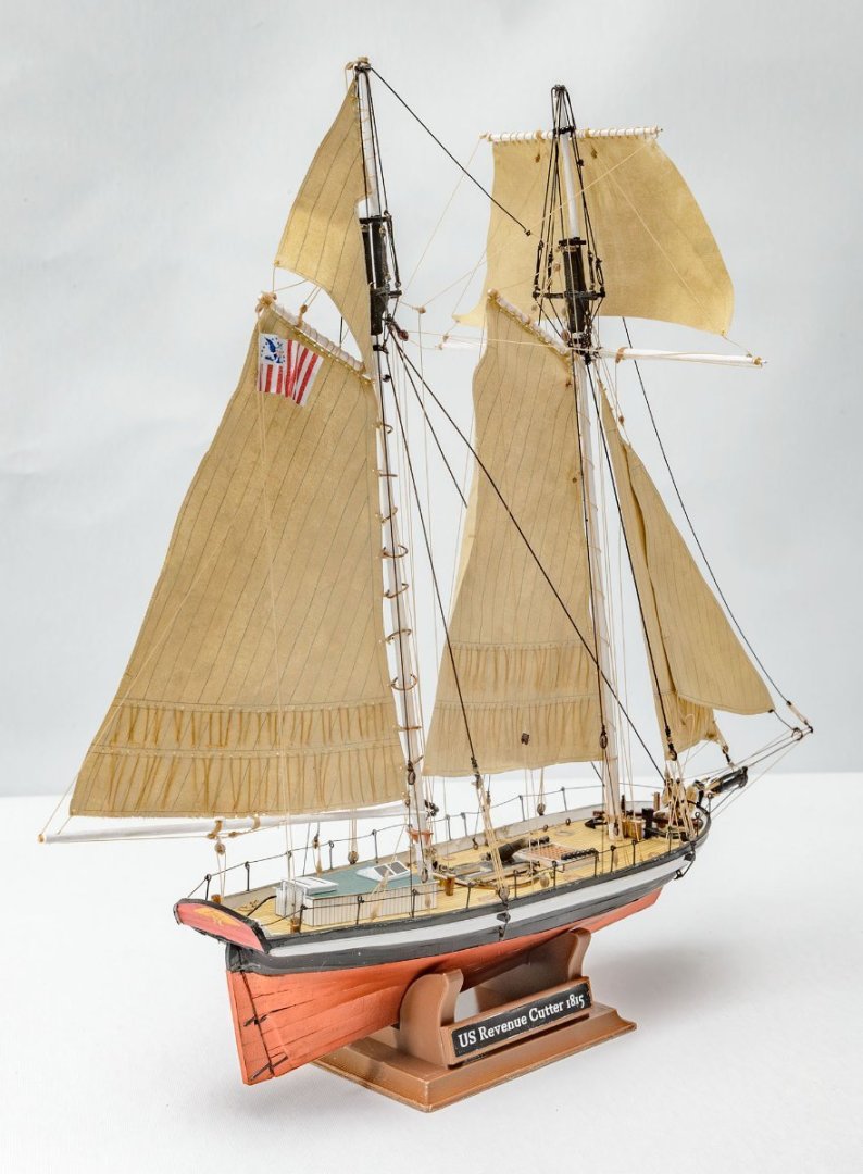
Here is completed one.


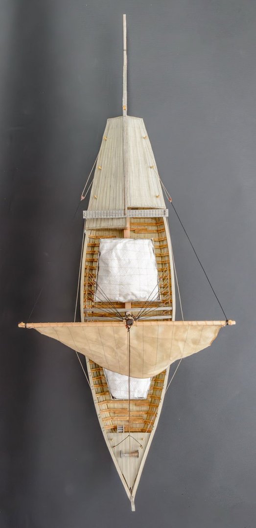


Please consider it an unpainted or semi-assembled model. I missed some parts or made mistakes.
I discovered more errors in the kit during the later procedure, which were identical to the previous errors I found. The errors are repetitive.
1. The manual format isn't user friendly. There are too many things in one scene, and sometimes the instruction isn't clear because of lack of information.
2. The manual occationally misses descriptions for some parts. Most of the missing parts are essential to complete the model.
3. The manual is designed for the kit's stock paper only. When I use laser-cut parts and glue colored parts to them, it is very sensitive to the directon of adhesion. I didn't pay attention to this, which resulted in some part becoming unrecoverable.
To succeed in further card board models, I need to be more careful.
1. Scan everything and reprint it when you need it - Some critical errors may require editing the scanned picture or building new parts.
2. Temporary assembly - Don't glue and paste as the instruction say. Put a cut part on the model and ensure that the fit or direction is all correct.
3. Need a better manual - I've seen several card board model kits, and their instructions are too difficult for a 21th-century boy. The manual format needs to be refined and expanded to include dozens of pages.
Also, additional instructions for optional laser cut parts will improve the building experience.
The card board model is quite difficult and sensitive, but my eyes can't leave their exotic kits...
- ccoyle, GrandpaPhil, mtaylor and 3 others
-
6
-
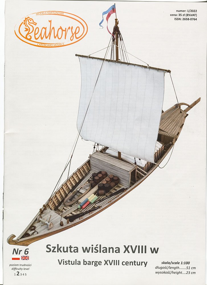
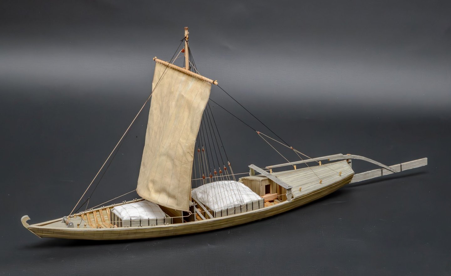
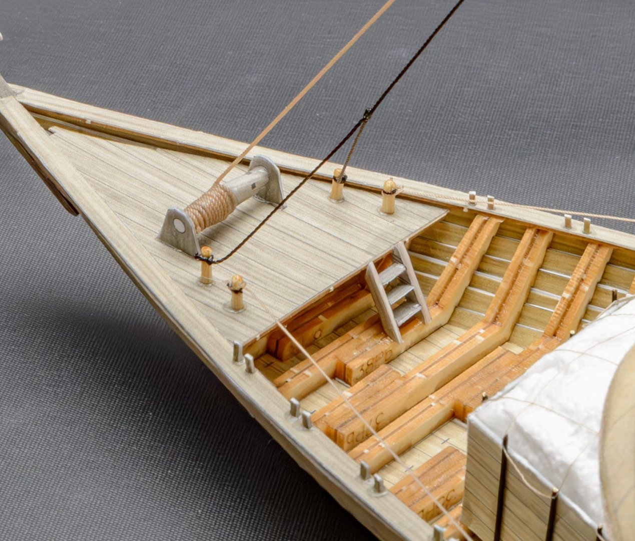
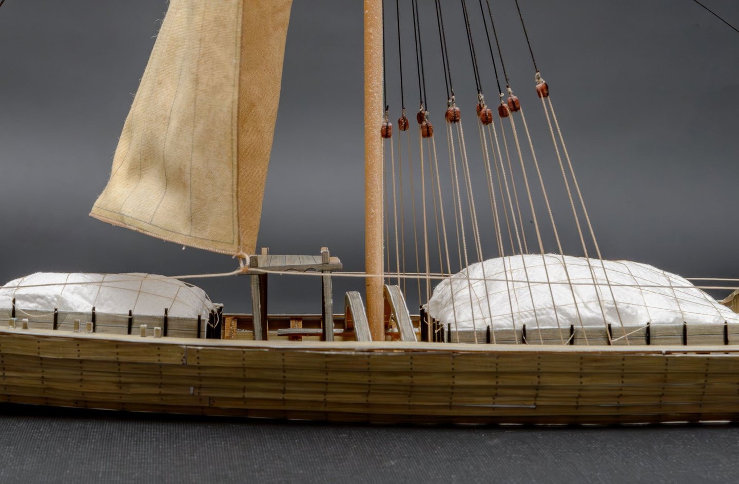
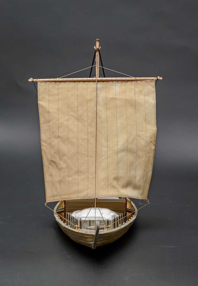
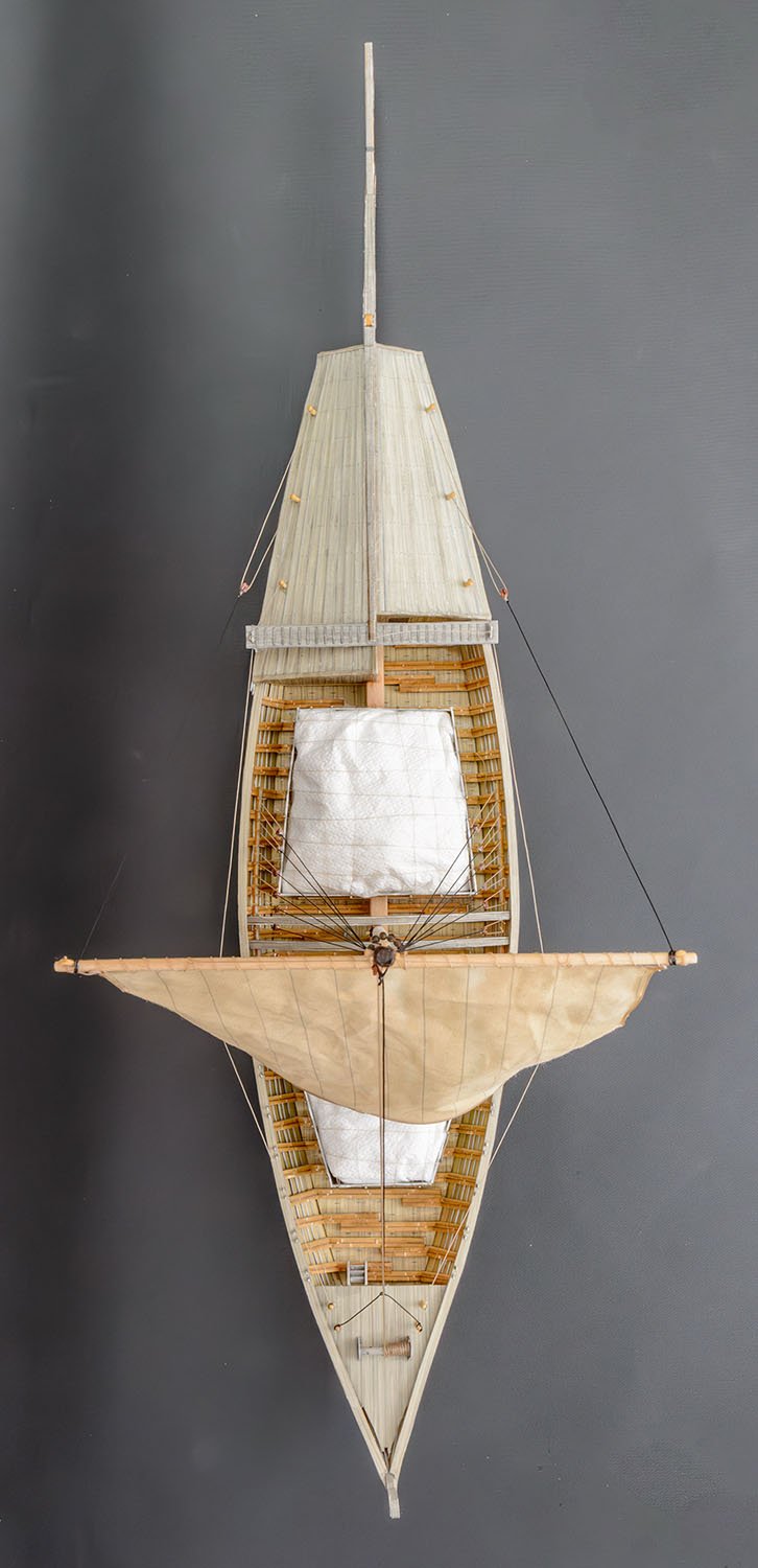
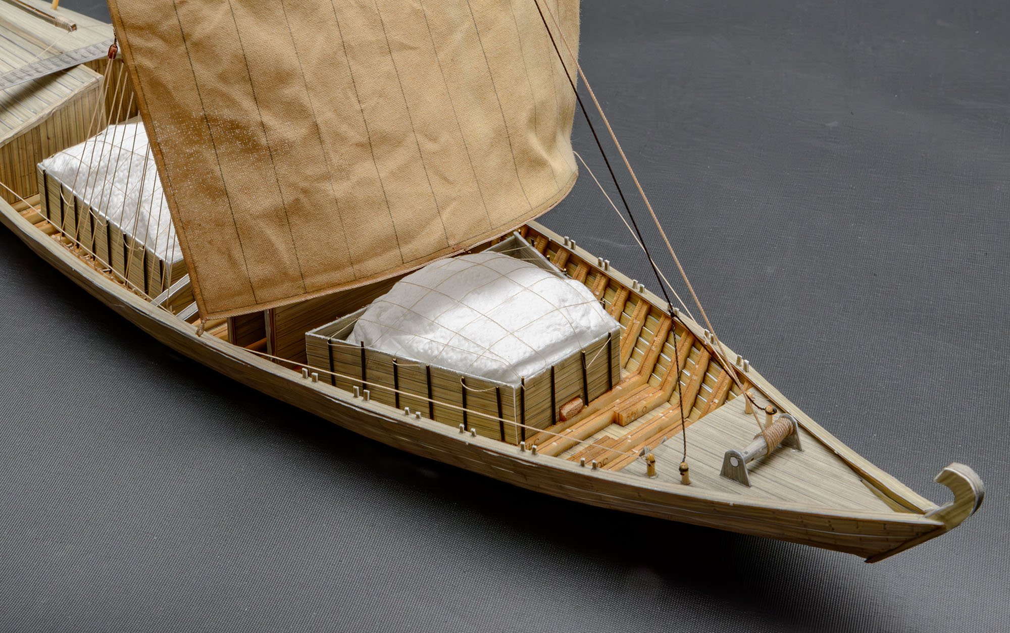
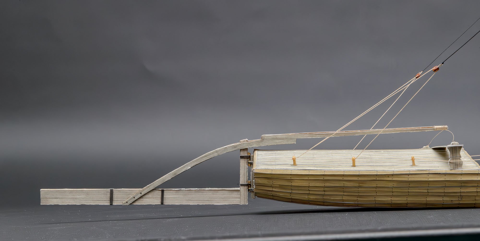
This is another short term project. I'm focusing on new experience, so I'm building this kit quickly, regardless of quality.- Kit name: Szkuta Wiślana XVIII w (Vistula barge XVIII century)
- Maker : Seahorse
- Scale : 1/100
- Num : 2022/01
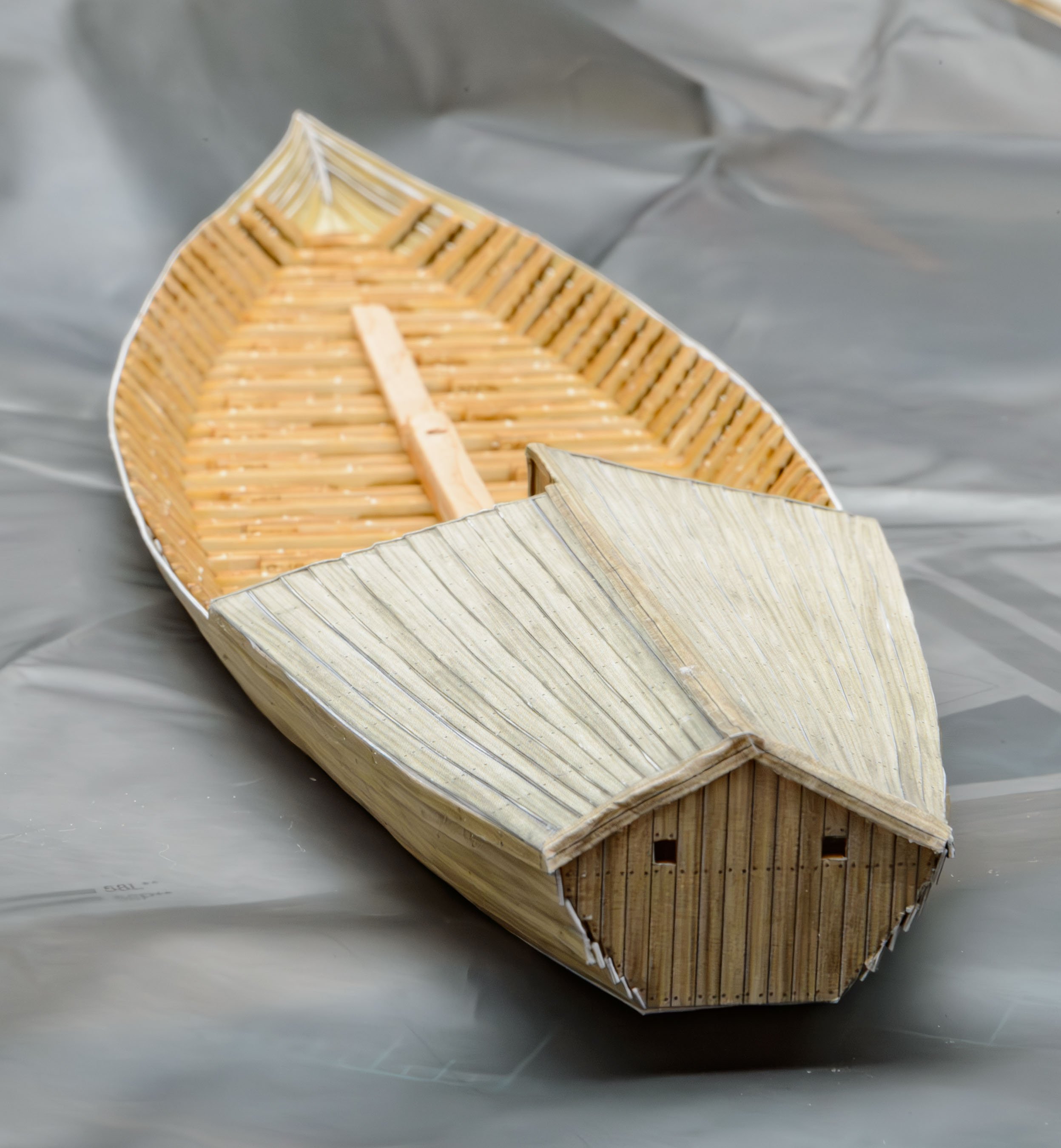
Here are the errors I found for two days.
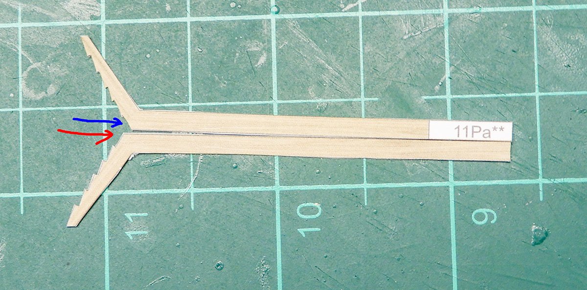
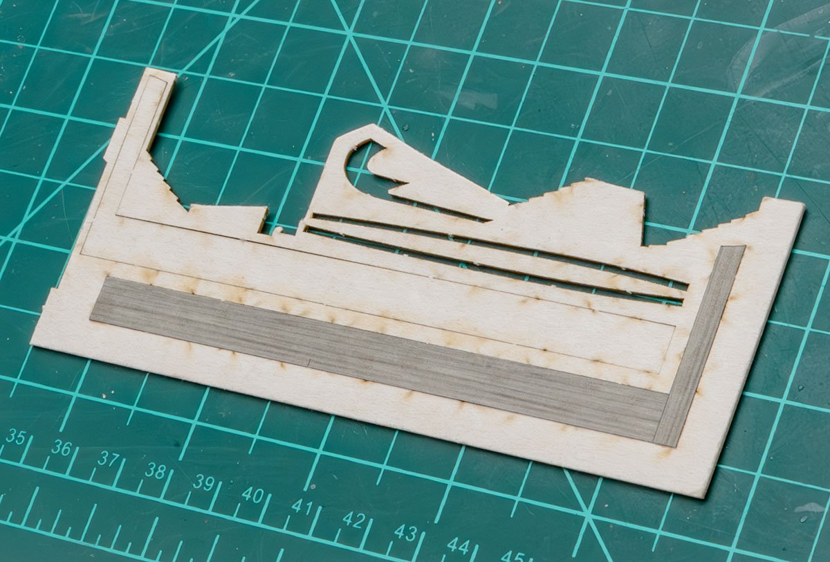
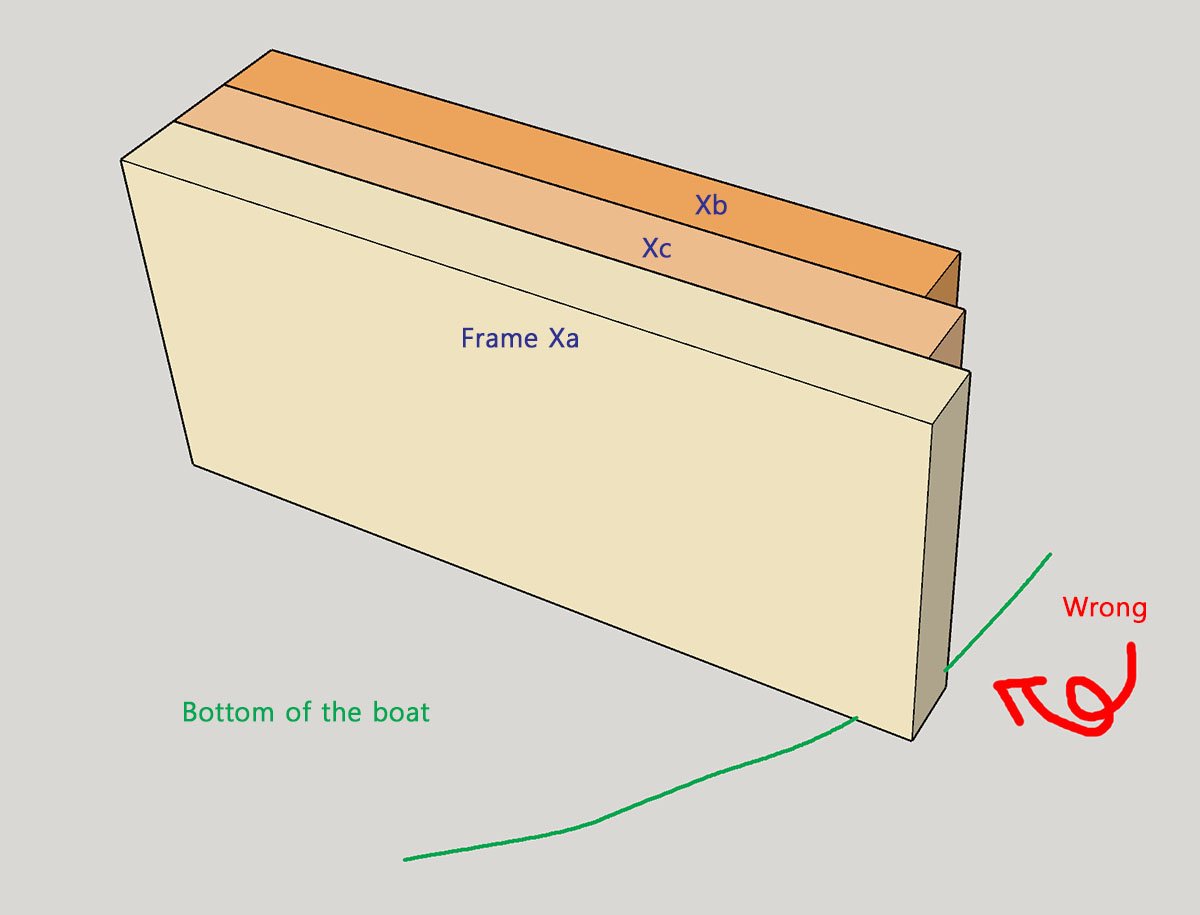
The frame consists of three different parts.
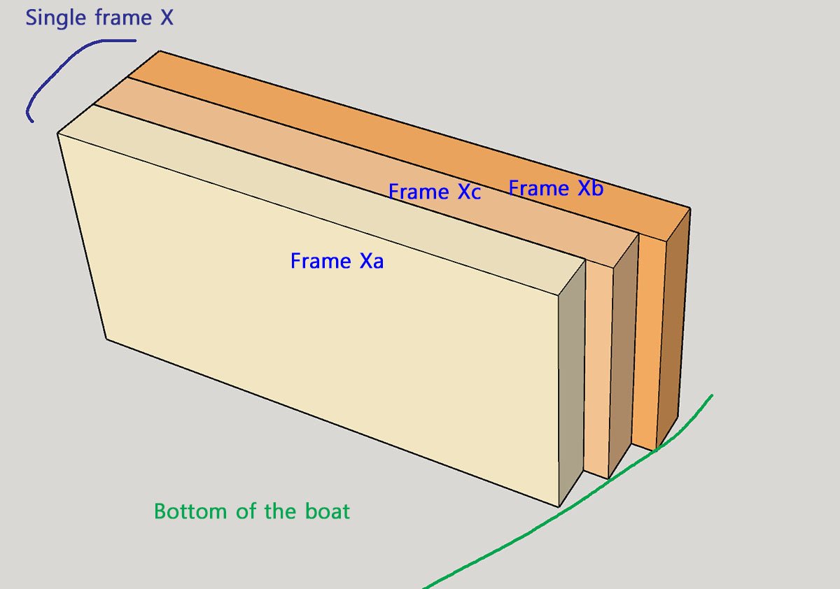
It is a clever design that solve hull fairing... only if the printing is all correct.
Some parts, such as 11, 12, 39, and 40, are printed wrong.
If I corrected the reversed parts and polished color parts, I had two options.
i) Scan, fix, and reprint color parts.
ii) Using white paper and painting on it, like the Shipyard 1/72 scale kits.
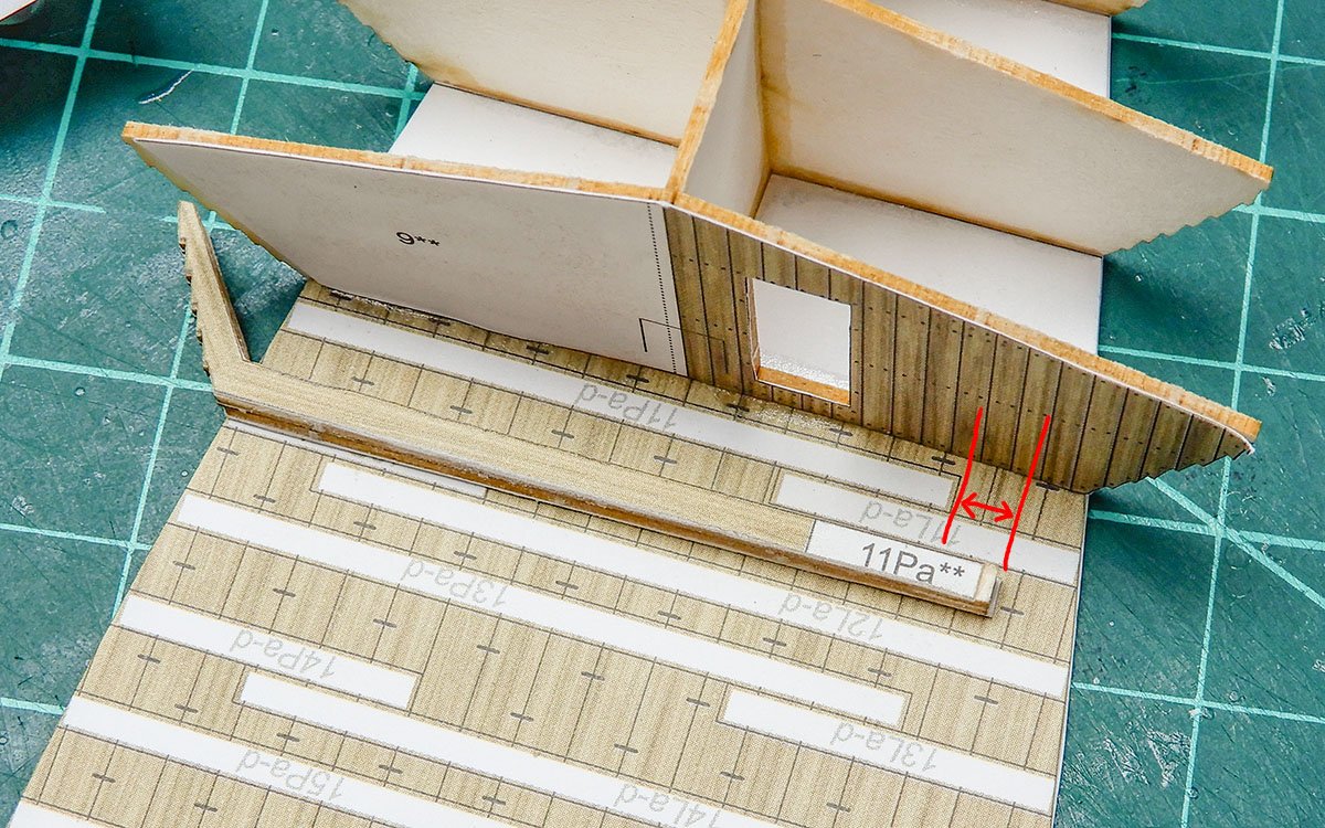
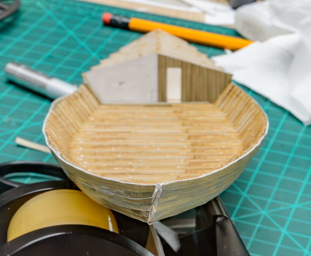
Many frames are larger or smaller than the guide lines on the boat's bottom. I didn't hide the white guide strips.
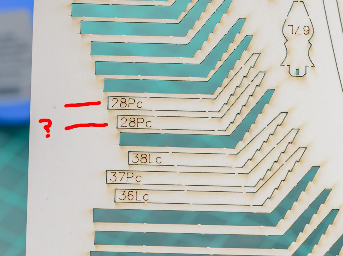
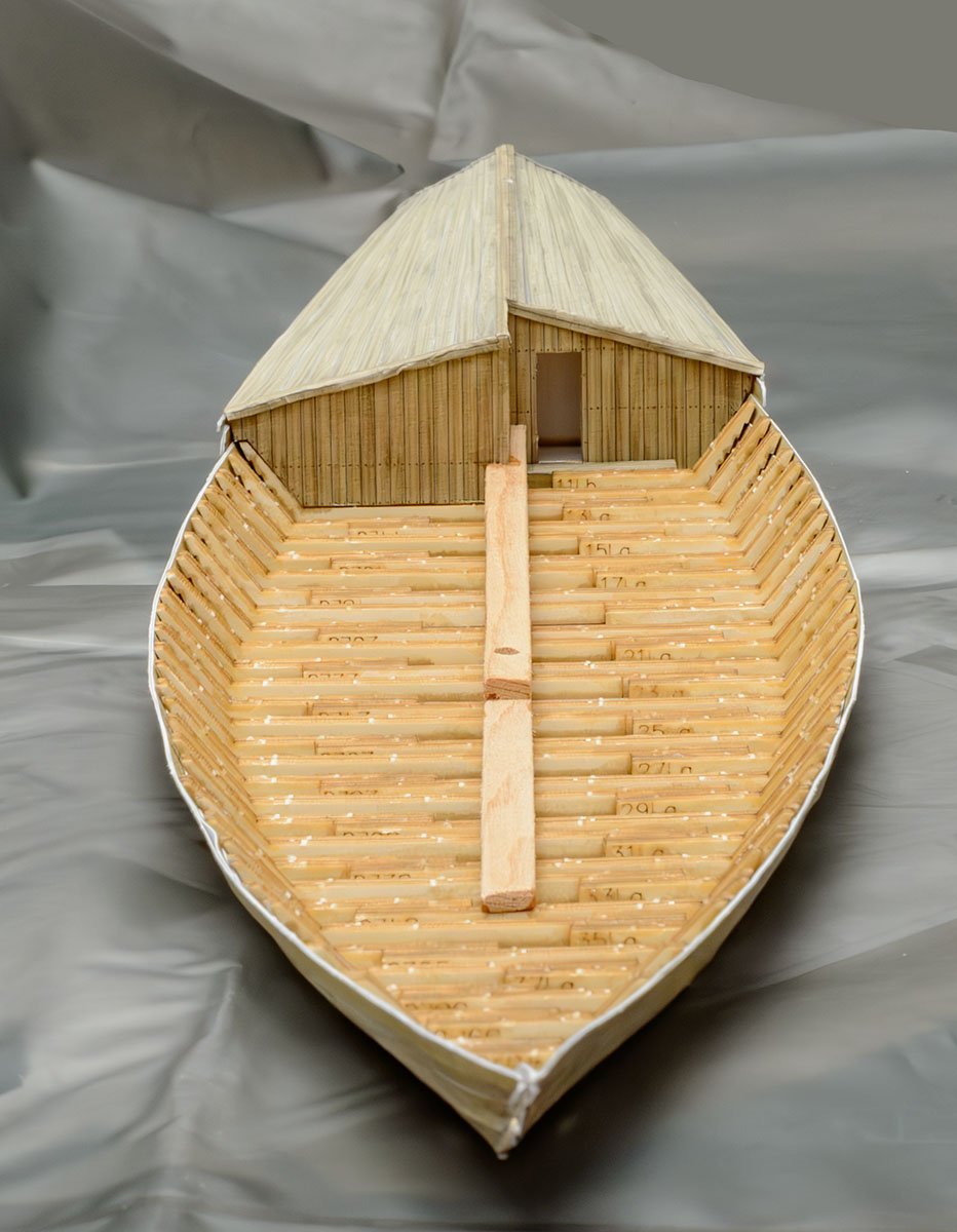
Here is another printing mistake. The 26-P-c part is missing, so I slightly modified one of the 28-P-c parts to replace it.
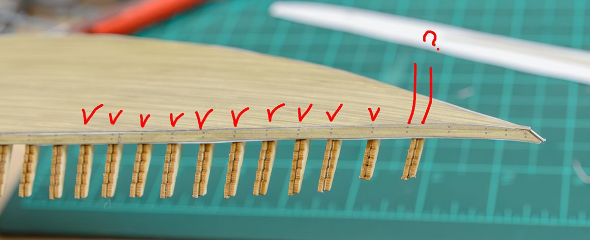
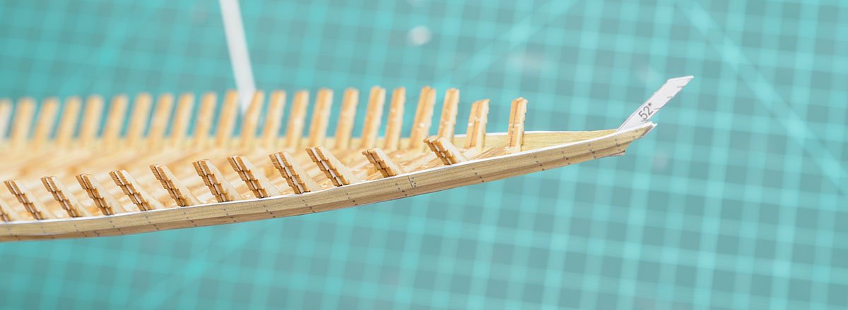
I estimated the frame position usingthe part 10's treenail marks. The marks indicate that the placement of frame 40 was incorrect.
The next procedure is planking.
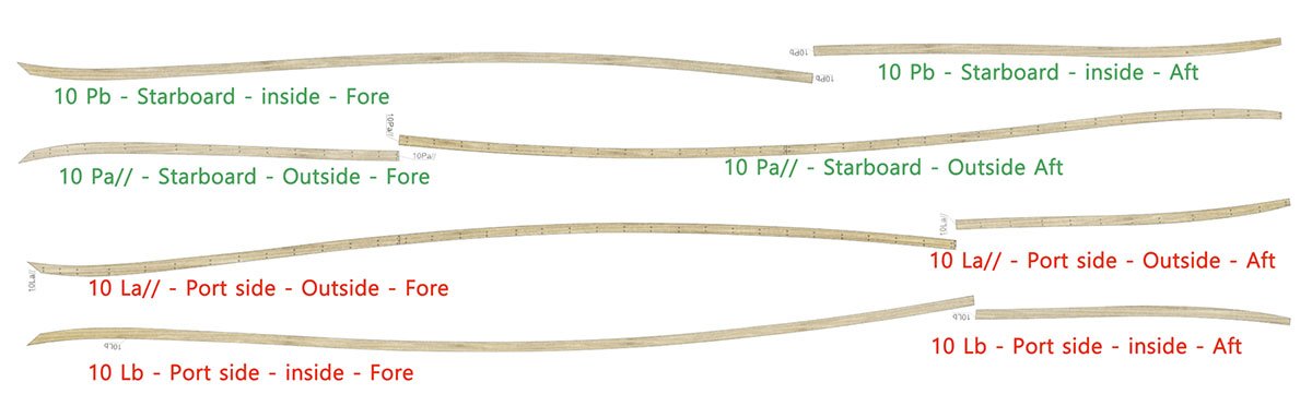
The manual is a bit confusing, so I reorganized the diagrams of each planking strip. Each planking strip consists of 2 inner and 2 outer parts.
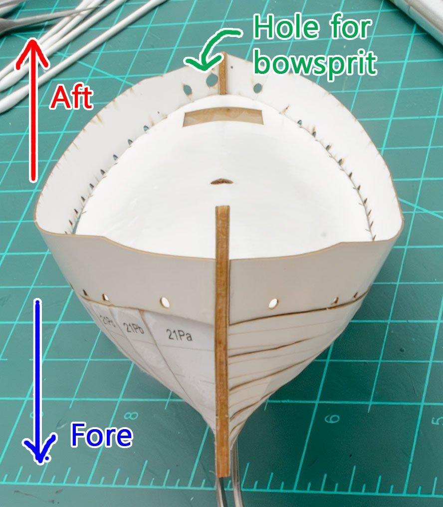
There is a guide paper at the stem.
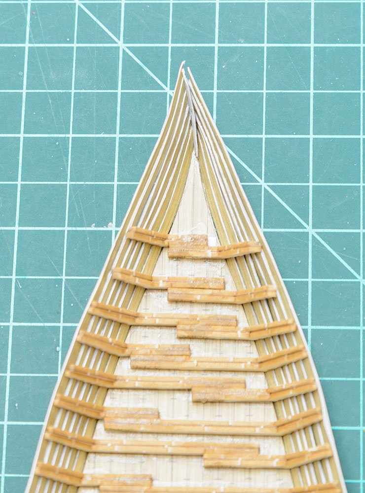
I didn't pay attention to the guide. Take care of it!
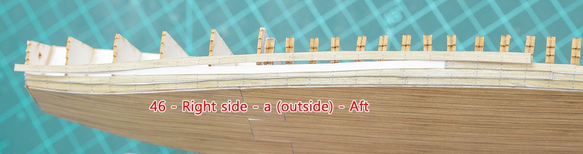
There are some missing parts or misprints on name tags.
46-L-a-Fore ← 48-L-a-Fore
46-R-a-Aft - missing
48-L-a-Fore - missing
48-R-a-Aft - missing
I patched the missing parts with other colored parts.


Day 2 of building...
- Mike Y, GrandpaPhil, mtaylor and 2 others
-
5
-
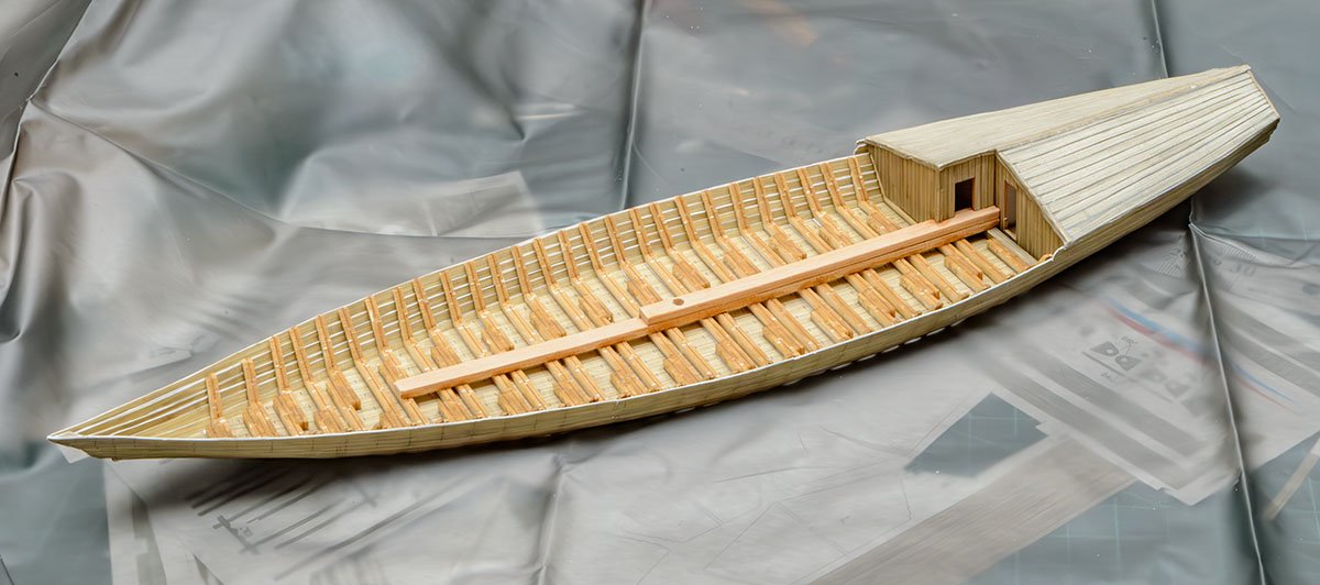
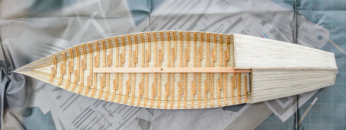
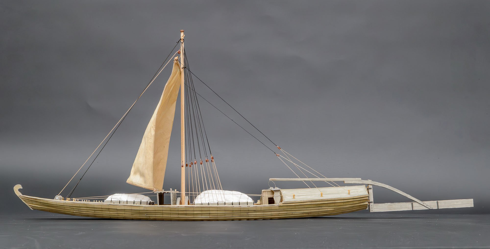
I made a catastrophic mistake while I was building. This is my correction note.
The kit information
- Seahorse
- Leudo Vinaciere
- 1/72 scale
- ISSN : 2658-0764
- Num : 2020-02
- CARD (paper) model
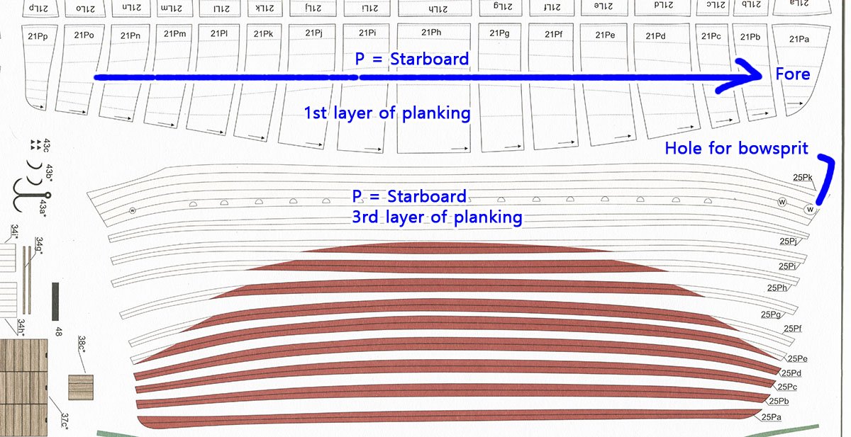
The first layer and third layer of plankings are good to go.
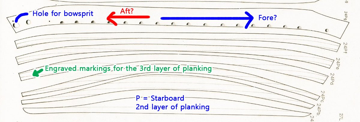
However, the second layer of plankings is incorrect.
Because I followed the manual, I made an unrevokable mistake. To correct the error, flip the second layer of planking over and stick them on.
I may buy the same kit and try it gain in the future...
- shipman, GrandpaPhil, mtaylor and 1 other
-
4
-
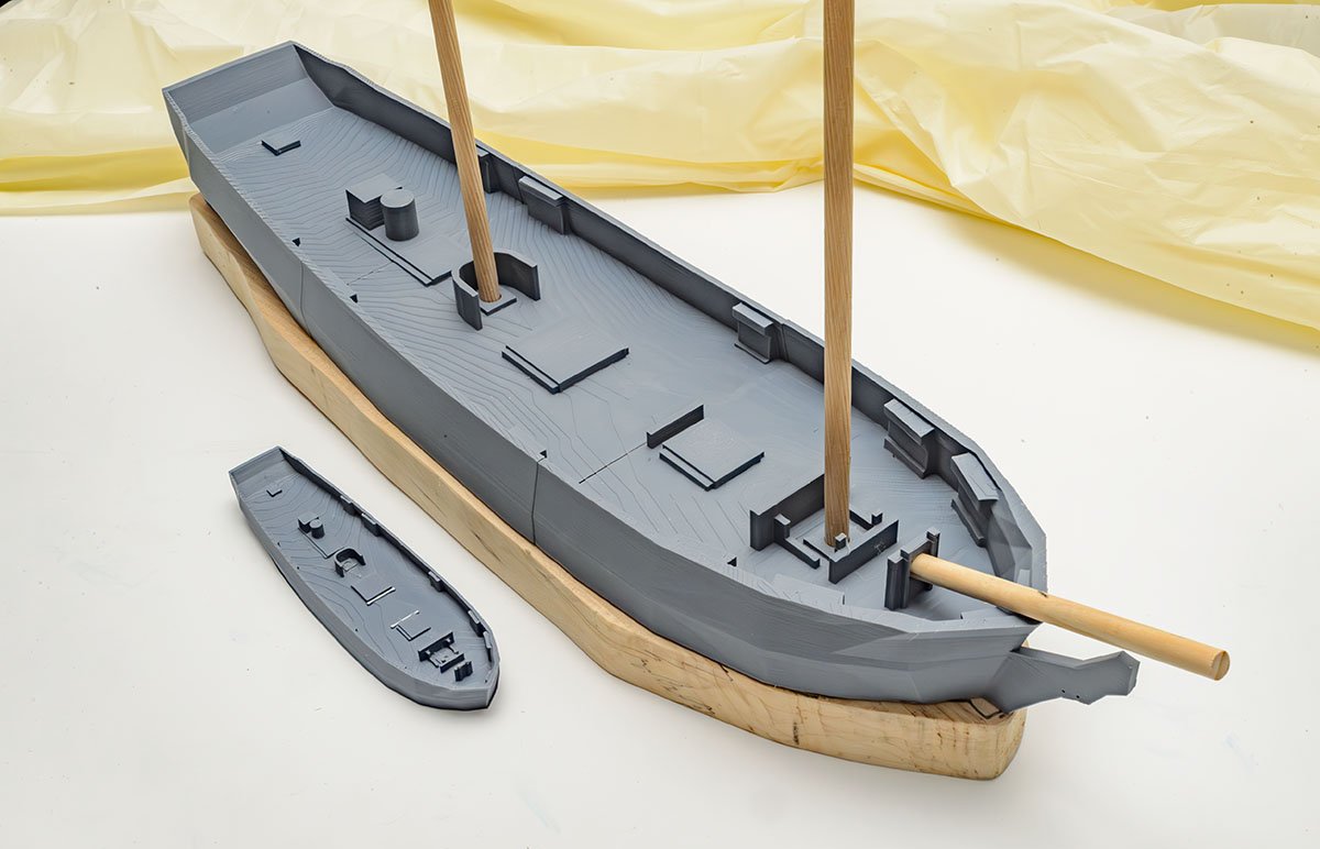
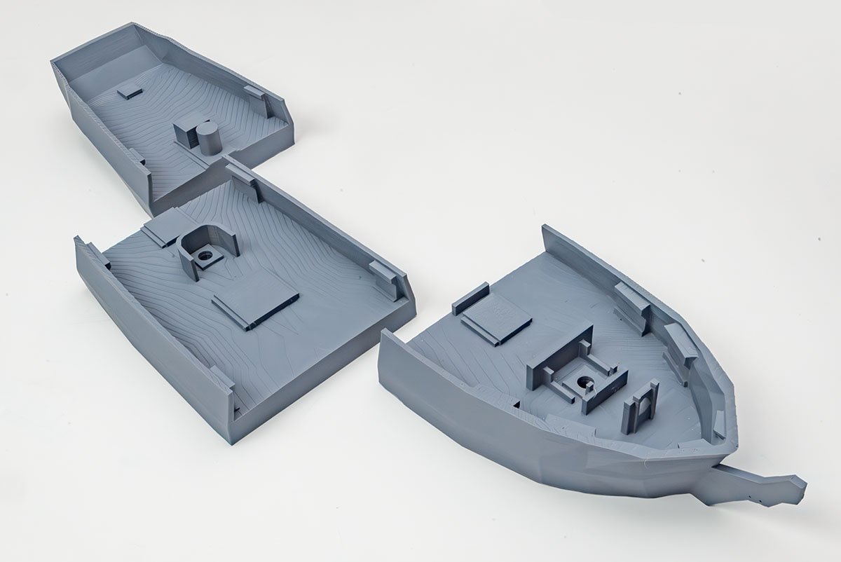
I made a 3D printed hull before I started to glue the wooden keel and frames.
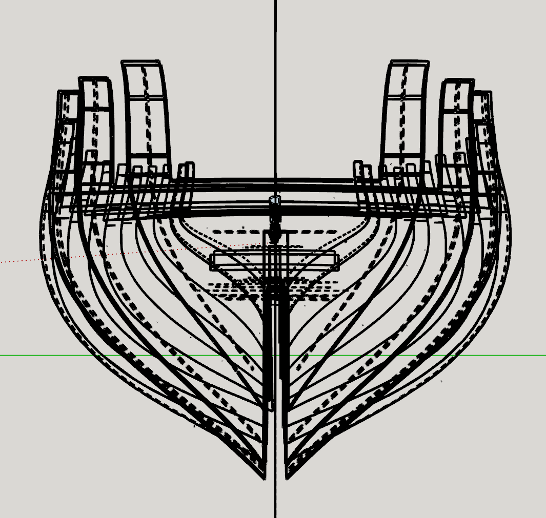
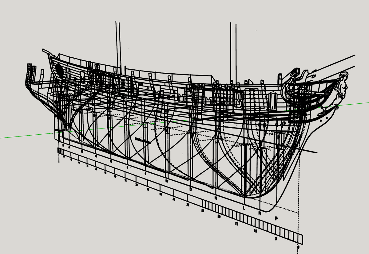
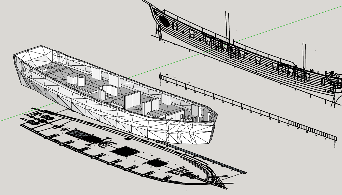
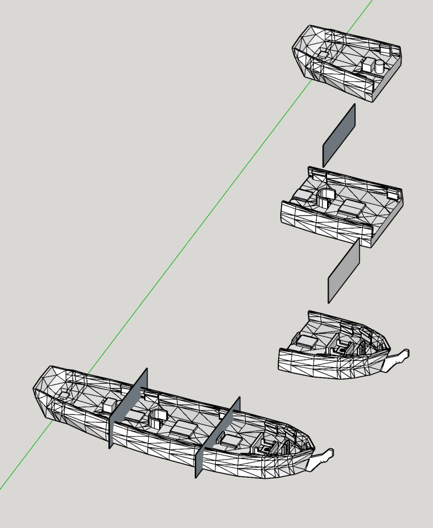
I scanned the original plan and made 3D models to print the hull. Due to copyright reasons, I can't share my modelling files.
I wanted to find a new way to enjoy the kit. I skip all the processes before rigging.
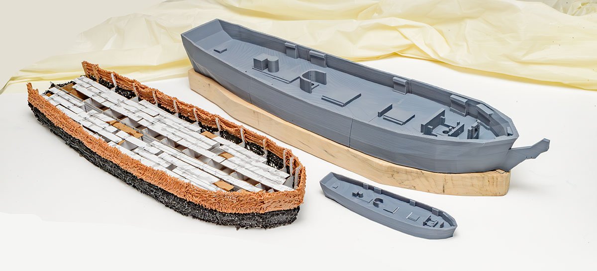
I tried several different methods to build copied hulls. For example, I tried a 3D pen to draw hull planking. Unfortunately, it was boring and tough work. After several attempts, straight 3D modelling was the best answer. The small ship is 1/210 scale version.
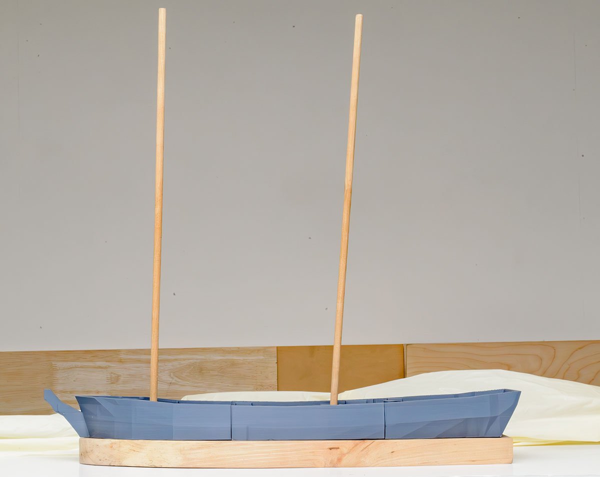
I'm going to build a wooden hull with the 3D printed hull for rigging together. The second hull for rigging will be my trial and error test bed for the main mission.

- GrandpaPhil, ccoyle and CiscoH
-
3
-
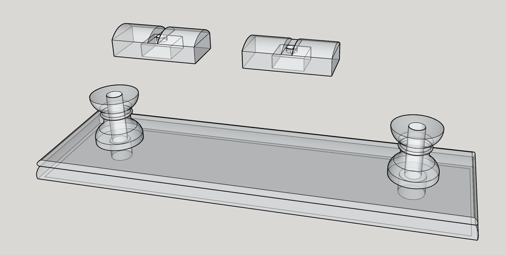
I made some display stands for the ongoing projects.
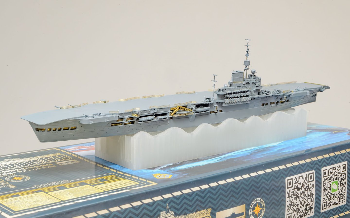
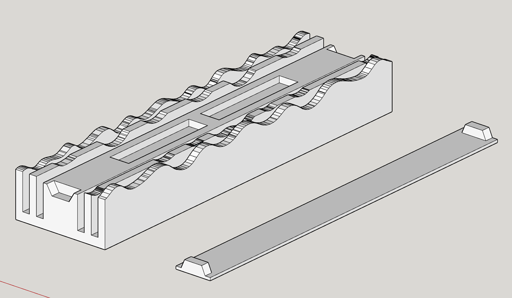
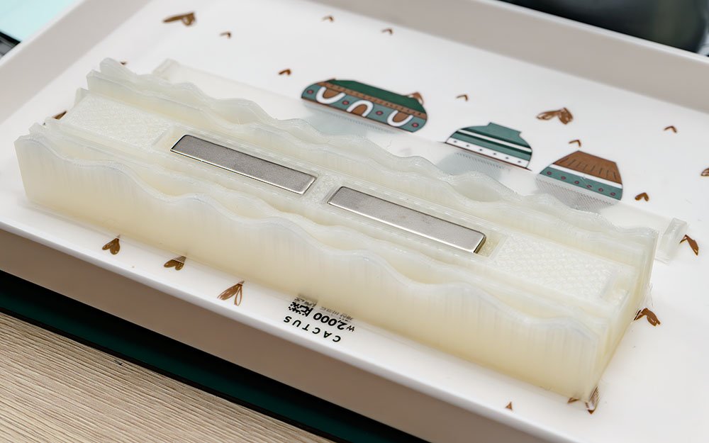
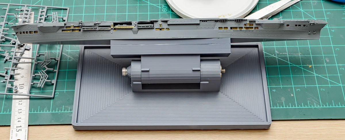
This is a building jig. It contains the same magnets.
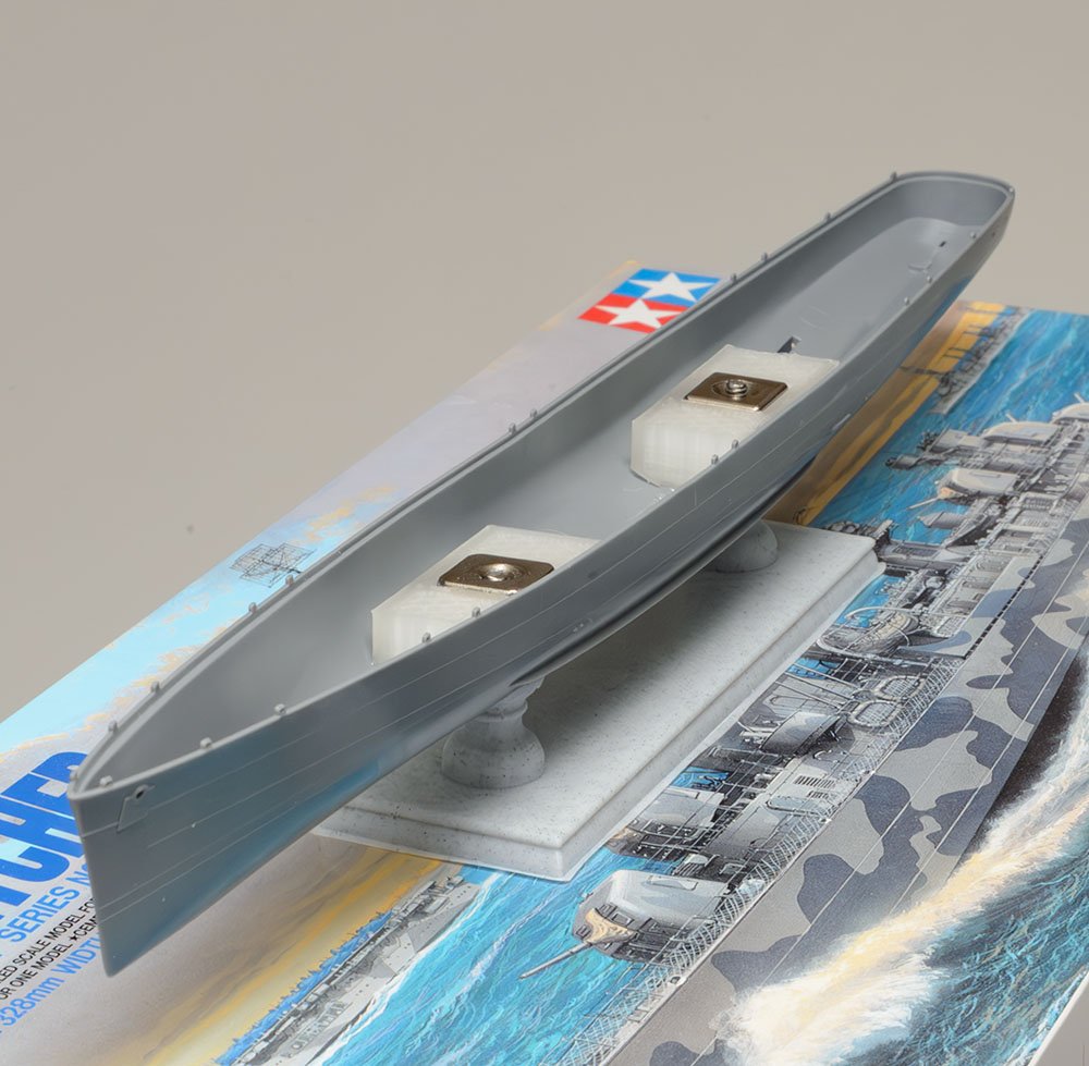
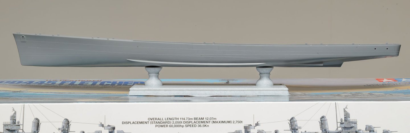
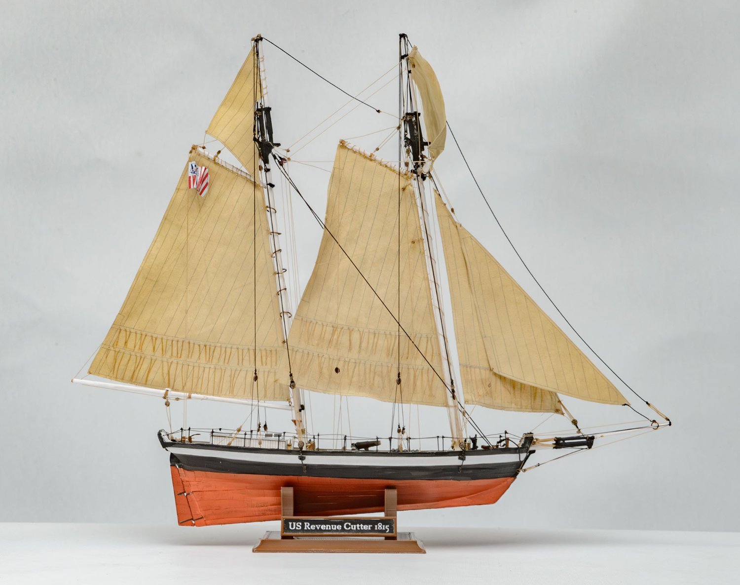
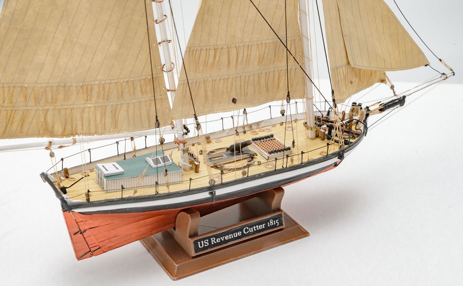
This classic kit will be the next project.
Classic design.
- thibaultron, Egilman and mtaylor
-
2
-
 1
1
-
That's a masterpiece work, Dziadeczek. A metal lathe was enlisted on my wish list a long time ago, but I can't buy it because there's no place to install the heavy machine.
I would say that my solution is dozens of times cheaper than commercial pins. Kit makers may include the 3D printed belaying pins instead of the large and thick wooden pins.
-
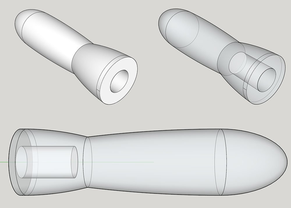
Here is another small project.
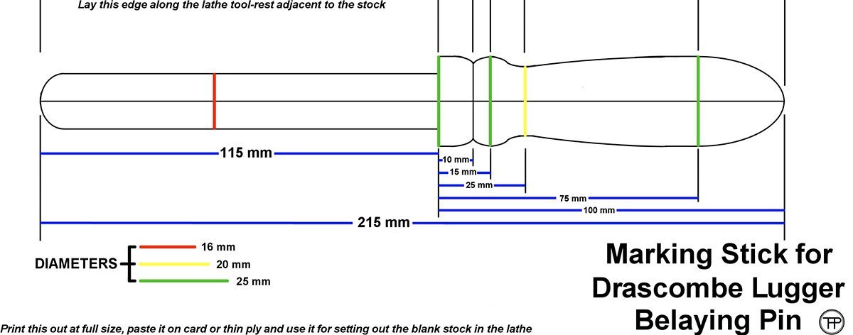
The design of the belaying pin is based on this plan. It is an 8.5" long and 5/8" thick belaying pin.
https://www.pettigrews.org.uk/odg/wt-project-01.htm
The USS Essex used an approx. 20" long belaying pin, and the HMS Bounty used an 18" long one.
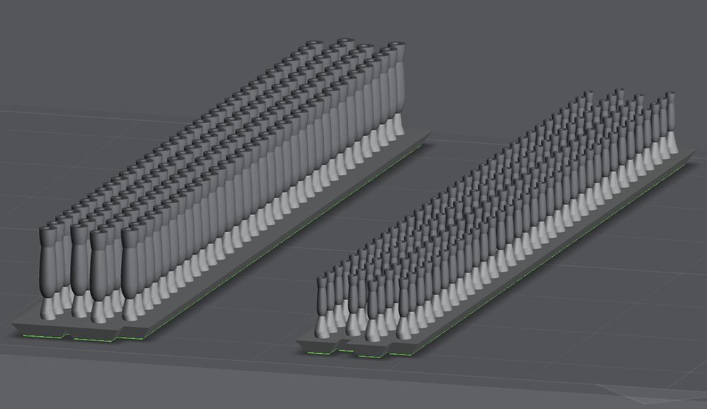
This is the most successful setting. I can build 2,000 pin handles per plate.
3D Printer : Phrozen Sonic mini 8K s
Setup : 0.020mm
Resin : Standard brown
Support tip : 0.70~0.60mm
The 1/72 scale of an 8 inch long belaying pin is not practical.
The 3.0mm belaying pin handle is the minimum size, with a little annoying assembly work.
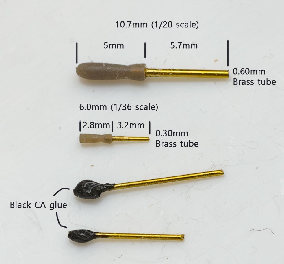
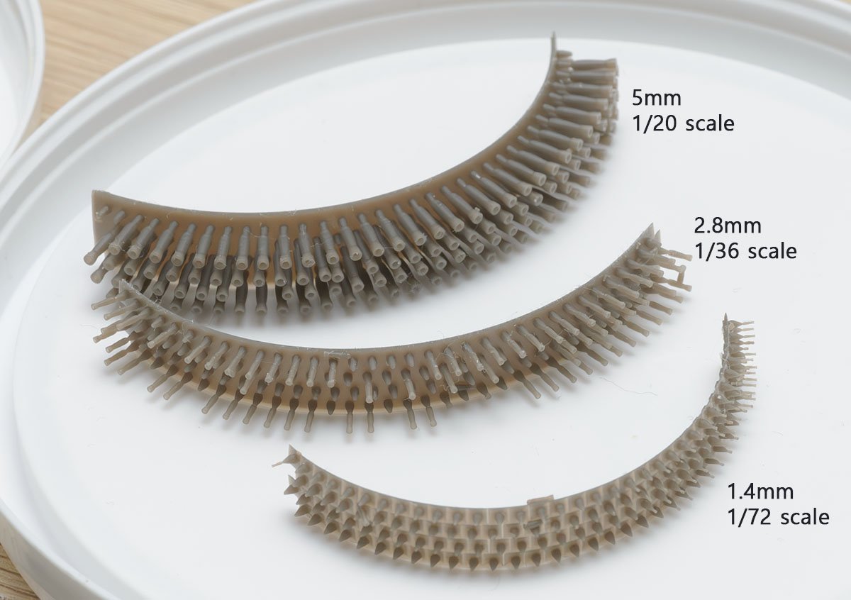
Here is the result. I would say that 6.0mm long with a 2.80mm handle is the minimum size for my 3D printer. If the ship is USS Essex, the 10.7mm long belaying pin is 1/48 scale, and the 6.0mm pin is 1/85 scale.
The 3D printed belaying pin (handle) will be my priority choice. It is definitely better than my previous method, CA glued head. -
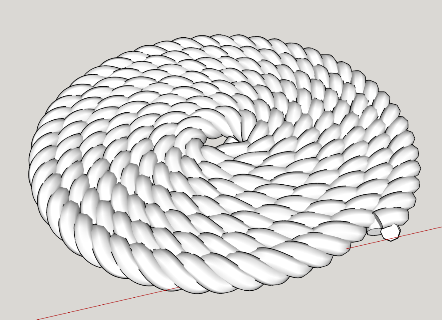
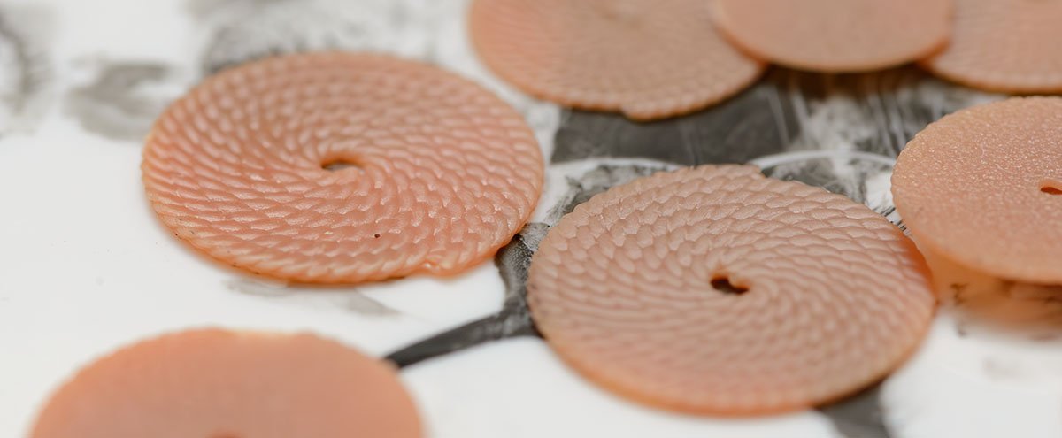
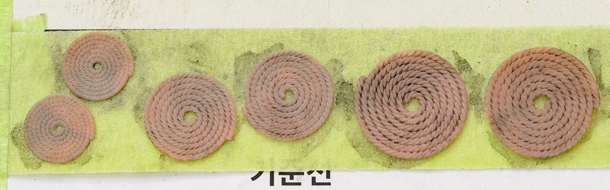
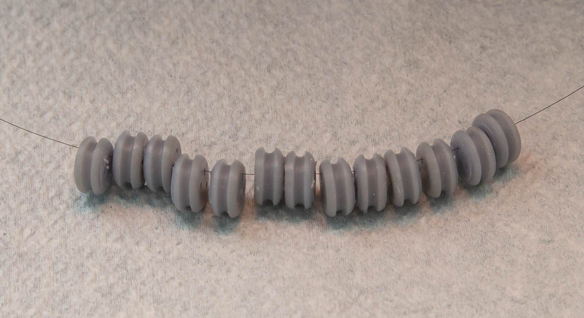
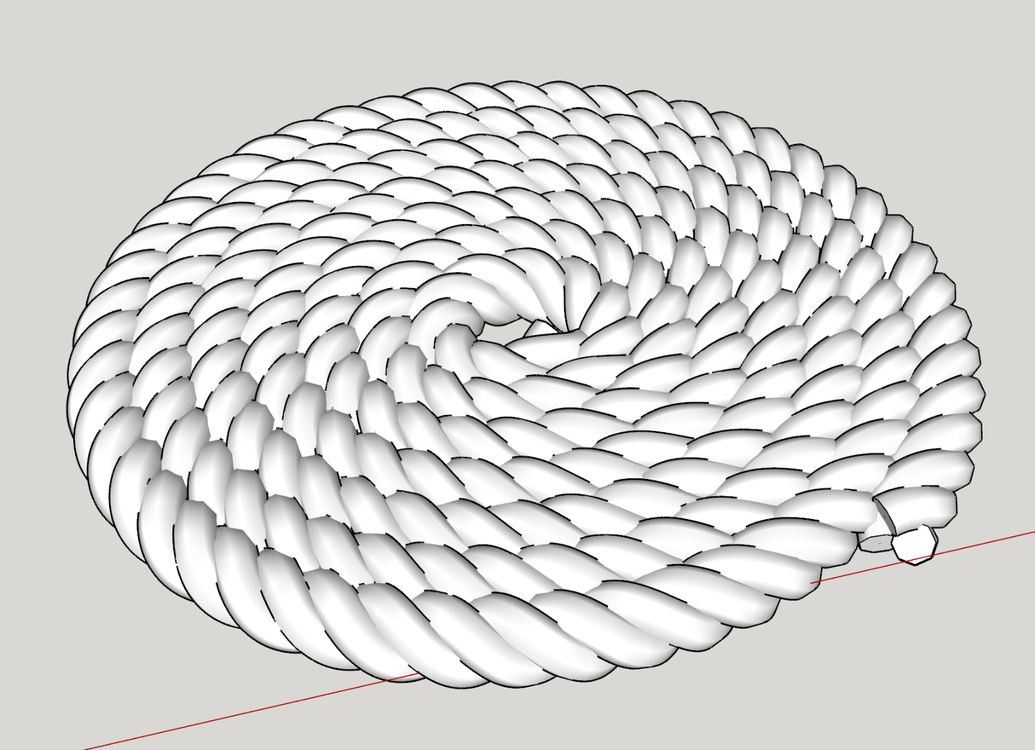
I made some 3D printed ropehank for cannons.
The result is great, but I can't say it is significantly better than the traditional method.
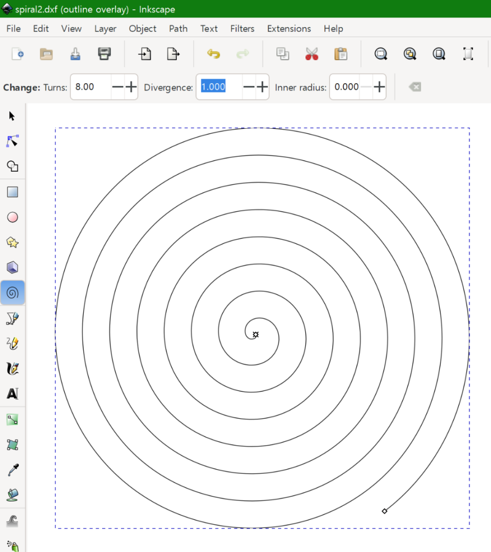
Here is how I made the ropehank.
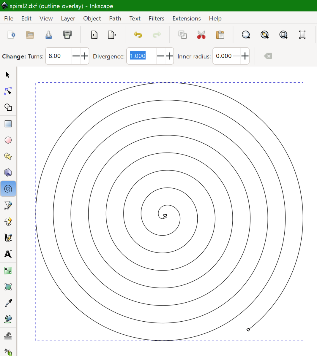
1. Inkscape
1-1. Spiral
1-2. Save as vector graphic format for 3D cad software.
2. Sketchup
2-1. Load the spiral vector.
2-2. Delete the center of the spiral. (360 degree = 1 turn is enough.)
2-3. Extension - Helix along curve tool 0.9.0
3. Lychee slicer
3-1. Thinnest setup - 0.020mm
4. Painting
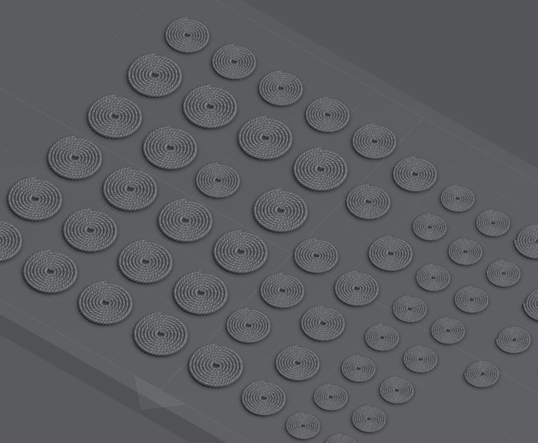
I printed three different sizes - 0.80mm, 0.65mm, and 0.50mm.
Here is a comparison with the traditional method.
Good
+ All the outputs have the same size and the exact same circle shape.
+ Easy to change the size and thickness.
+ Faster speed when mass-produced.
Bad
- Not time and labor effective if the ship doesn't have 74 cannons or more.
- It may be difficult to paint the plastic in the same color of the rope.
This method would be an interesting option if I build a plastic kit of ship of the lines. The next challenge is a more common ropehank with an integrated belaying pin.
- thibaultron and mtaylor
-
2
-
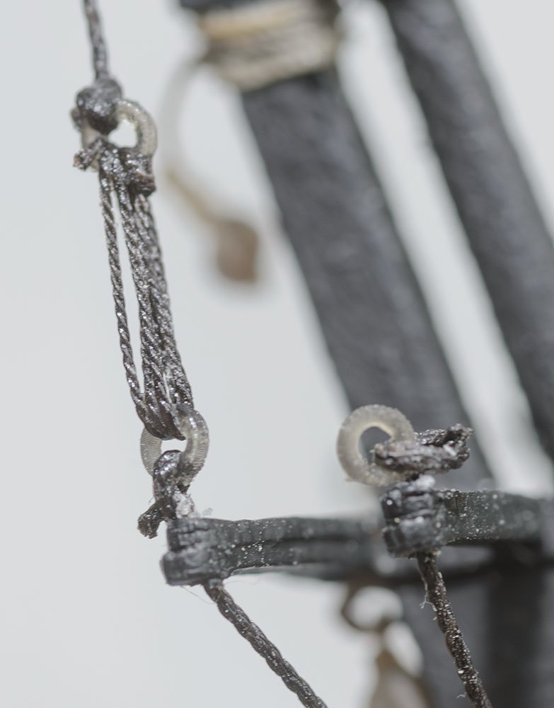
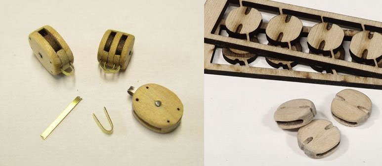
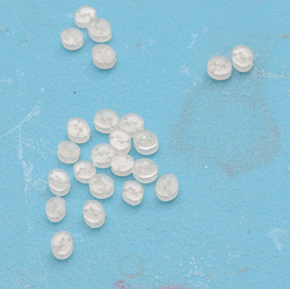
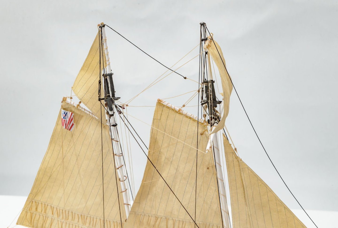
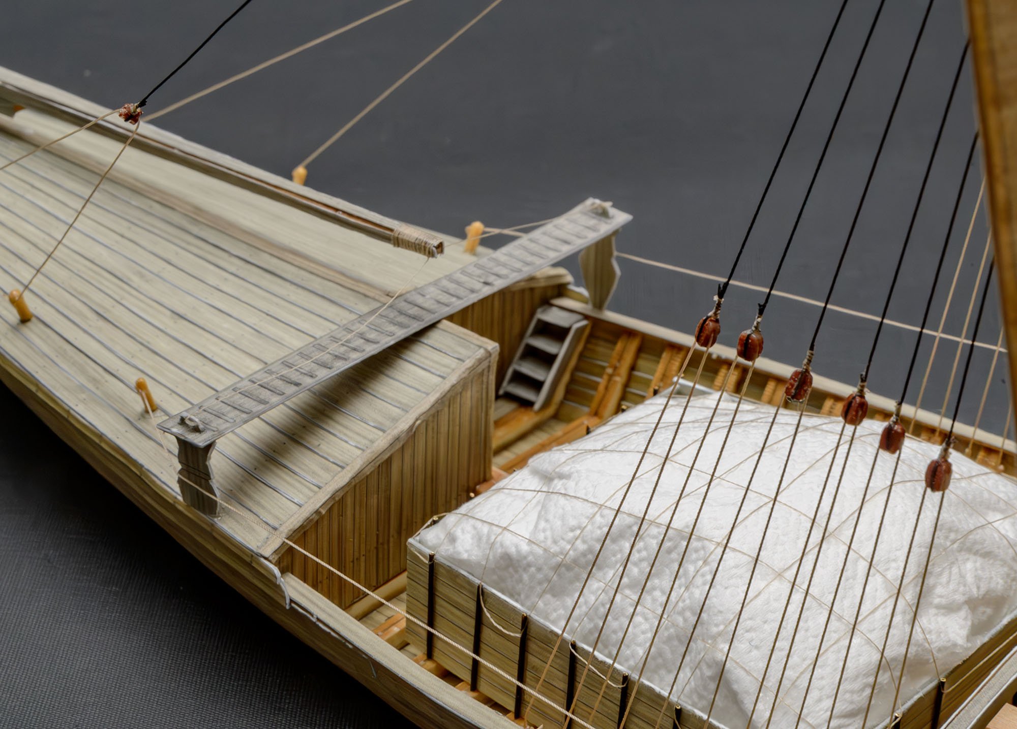
I guessed that the tiny rings supplied by the kit replaces the deadeyes. Unfortunately, the ring is very easy to break, so I made my own metal ring.
-
There are many reference pictures online, and I have good books, including the AotS series, but they are mostly 2D plan pictures.
For example, I don't know the depth of the center metal rod for pulley wheels. I just highlighted the rod by giving it a swallow hole. It was lucky that my guess was similar to the RMG image.
Those tiny details and hidden parts, including the structure, make me uncertain.
-
I use an old sketchup because it was familiar to me since Google made it freeware. Several years ago, the company was independent, and the newer version is paid only. 🤨
I considered moving to the F360, but Autodesk has changed the terms of service. The license for enthusiasts was downgraded to a personal license. Who knows what's next?
I have a plan to use Blender, which is completely open source freeware. I'm so lazy that I didn't open my textbook for blender.... zzz
-
Unfortunately, there won't be a cheap and accessible 3D printer under 0.010mm resolution within several years. The cheapest $150 resin printer uses LCD screen of a smartphone. The 0.022mm resolution is the edge of "commercial and economical" technology for now. We will see an upgraded resin printer when the Iphone's resolution goes to 8K, and then 1.50mm block will become feasible.
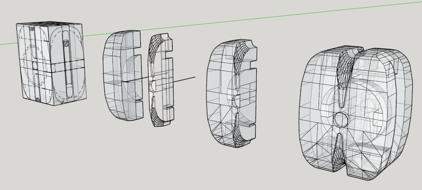
The 3D cad software is sketchup, which is not able to render curves.
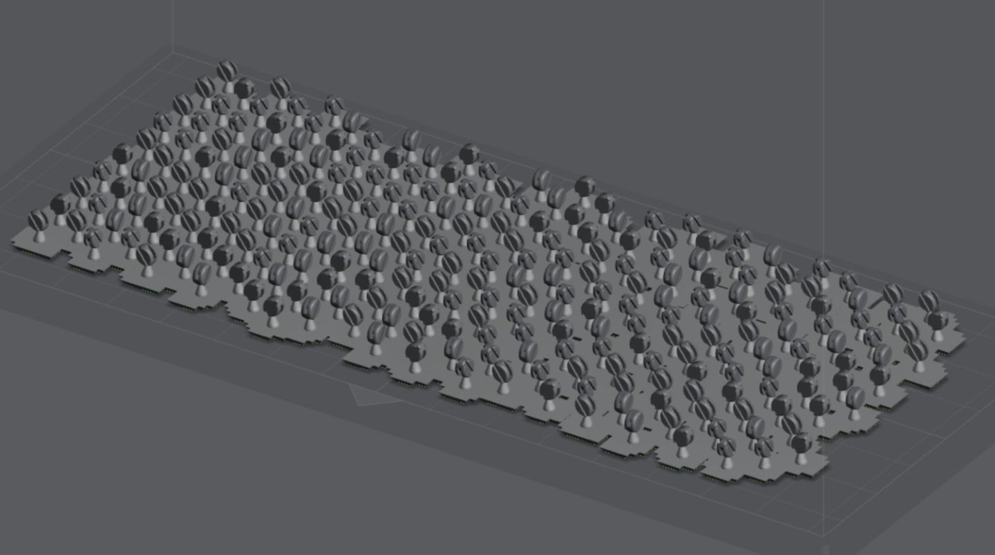
The last picture, which has an exaggerated groove, isn't my last 3D model. I just reused the picture to show mass-production.

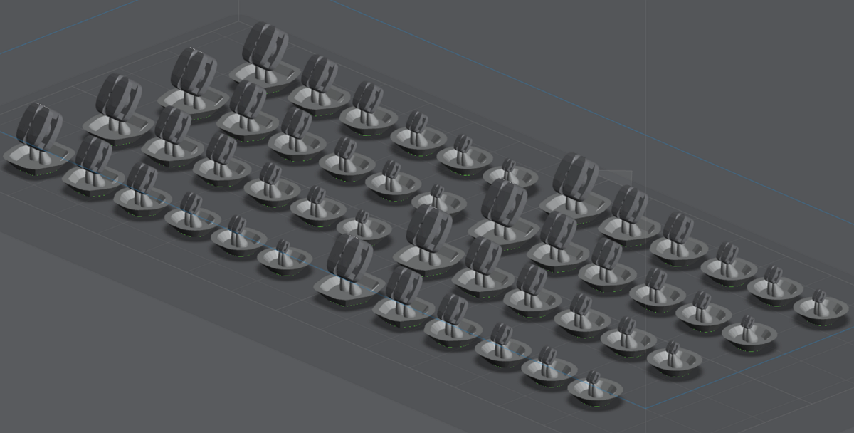
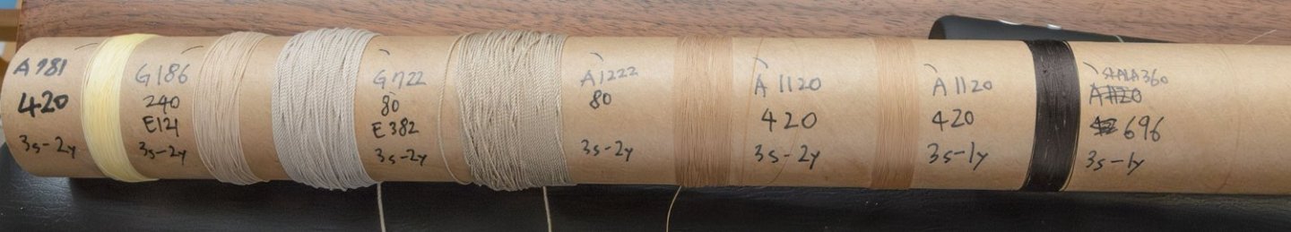
Here is my factory. The new blocks from 2.00mm to 6.50mm will last for years.
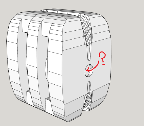
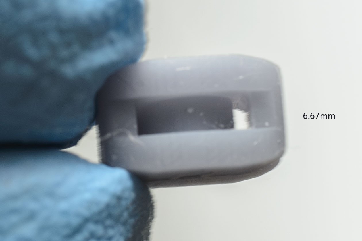
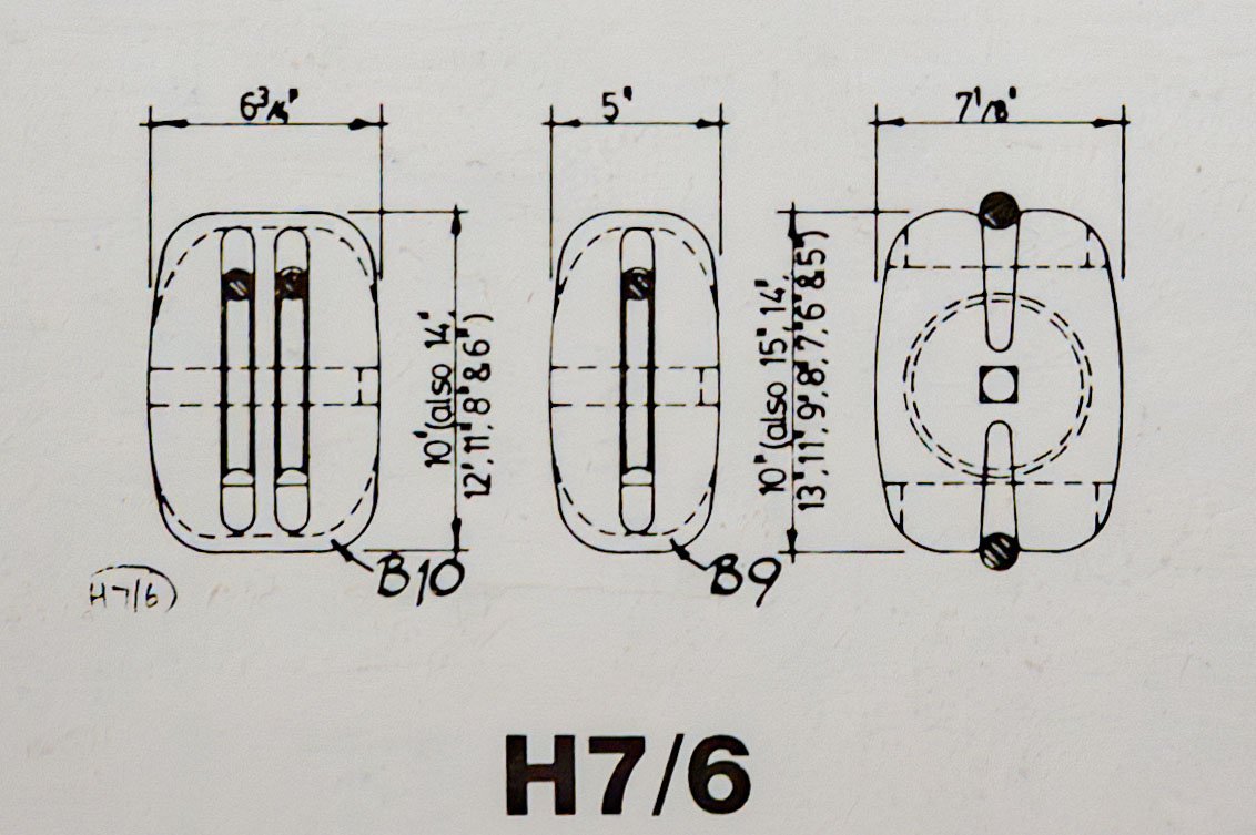
I don't know where the "slot" is. I haven't seen a real block, so I drew it based on the AotS book.
There are so many blocks in the Anatomy of the Ship books. It isn't difficult to build an accurate 3D model of the blocks. It is just a time and labor consuming job. I said that I spent 5 hours on the new model. I can't build and replace all the blocks at once. I'll collect various blocks one by one as I build more ships.
-
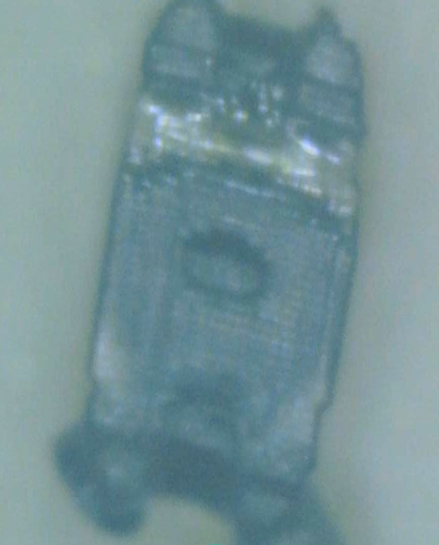
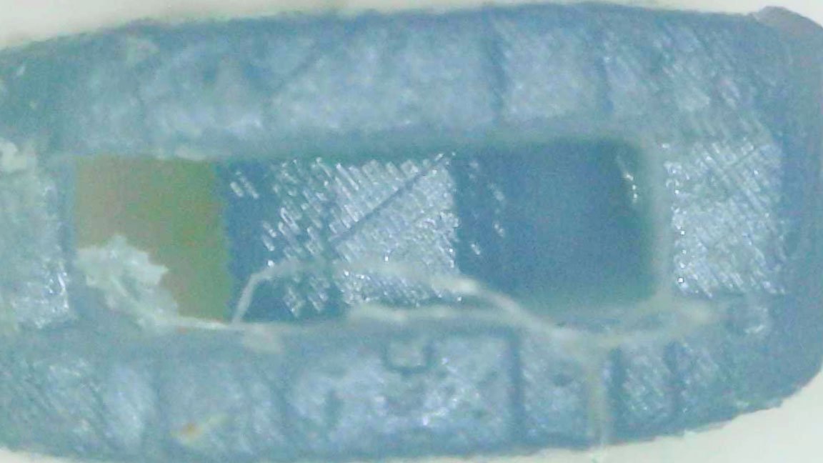
After several attempts, I took a picture of dust similar to the shape of a block. The size is 1.00 x 0.50 x 0.71 mm. It is impractical to use the 1mm block. The material isn't strong enough.
I would say that 2.00mm is the minimum size for average use.
Thank you for reading my experiment, and I hope you liked my answer.
-
That's easy question.
It depends on the size of the block (or tiny fitting parts). If the size is bigger than 4.00mm, people can notice the difference between wooden blocks and matt-colored plastic blocks. I would like to go to Syren's CNC wooden blocks when I build 1/48 scale ships.
If the size is under 4.00mm, the adhesive affect the color of the block. The wooden block absorbs some adhesive and darkens like water. When the tiny wood part goes dark, it is hard to tell if the block is made of wood or plastic. That's the sweet spot of the 3D printed resin blocks.
Because of this, I'll simply use the black or brown colored resin if the block is small enough. Painting isn't necessary. If I have only grey or transparent resin, I would have painted them with lacquer spray.
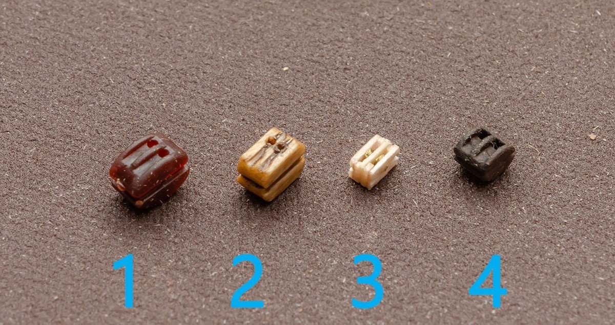
1 - Plastic - supplied by kit maker.
2 - AL's stock wood block
3 - DIY Paper block
4 - 3D printed + brown lacquer spray
Hanged before spraying.
The Syren's wooden blocks look good, but I may need to sand laser burn, and flatten the edges of it. I think this is what Allan said. Unfortunately, I don't want do it if the block is small. I'll buy Syren blocks bigger than 5mm. They are big enough to sand by hand, so it won't be a big problem, in my opinion. Small blocks are hard to sand, so I gave up and went to a 3D printer.
- wefalck, GrandpaPhil and mtaylor
-
3
-
The block picture is from Anatomy of the ship-HMS Bounty (or Bethia 1784 ). I checked the book. I have no idea about differences, but it looks like another interesting rabbit hole.
I think it is the beginning of building a digital library for modellers. As many people build 3D modeled blocks and contribute them, more modellers will download them from the catalog and build better models.

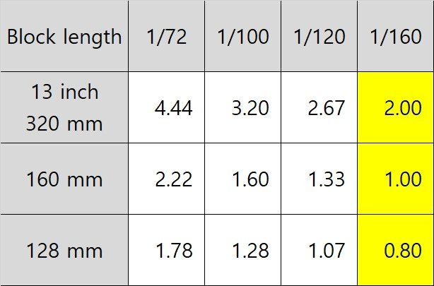
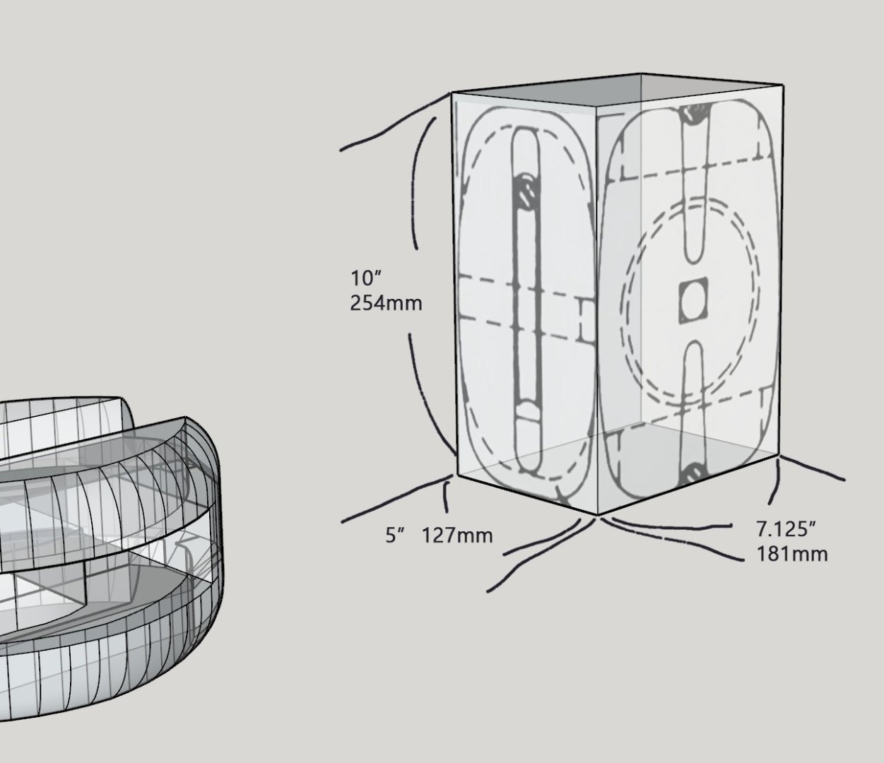
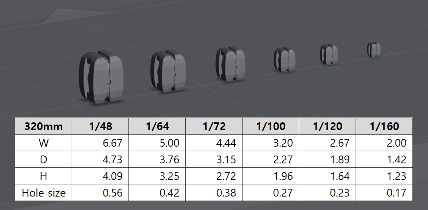
My 3D block model is based of the 10" plan. Let's assume the block size is 320mm or 12.5". The block size is 2.00mm when the scale is 1/160.
Copy and paste
The result was incredible. The details exceeded my expectations. They look like commercial 3D printed blocks, and they are also functional.
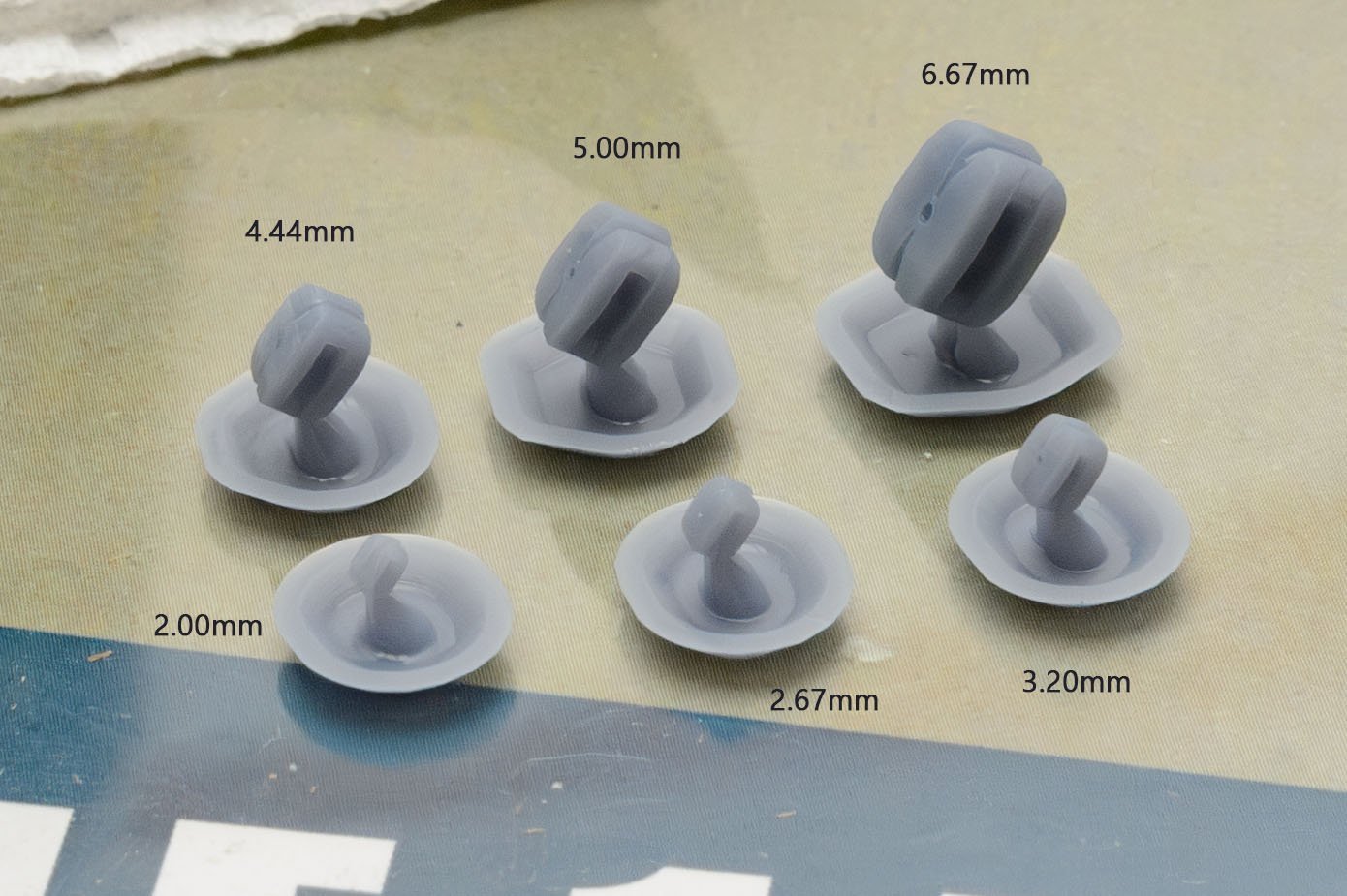
The 2.00mm block looks great. I pushed the performance of the 3D printer to the max. It is 3 times slower than the default setting, but it is worth the price of time.
The hole was closed when the size was under 2.67mm. I don't like finishing work, so I enlarged the hole.
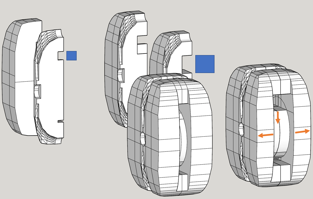
The external size is the same as the original. There are more ways to modify the hole.
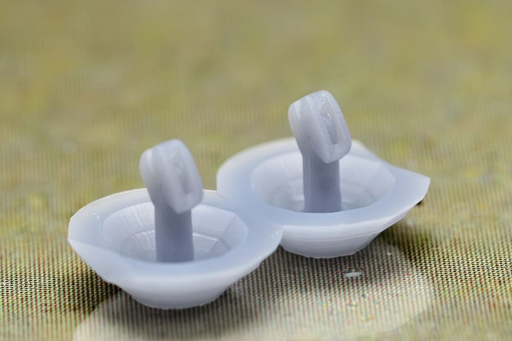
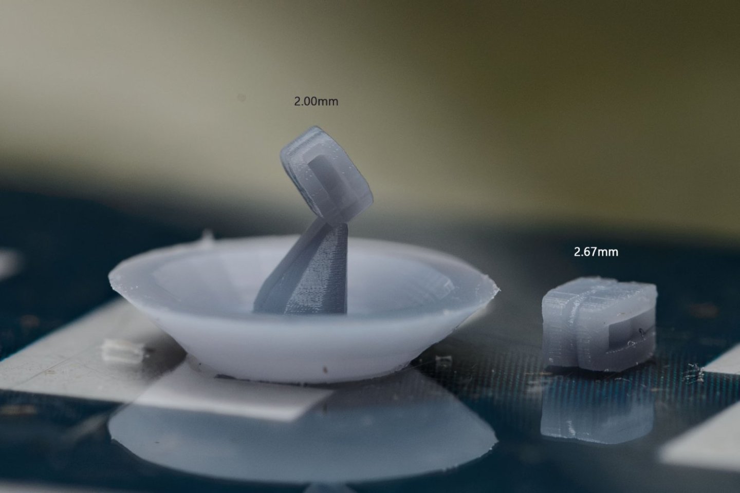
I tested the 2mm block again.
Thanks to the new design, it has a clear hole. Not all the blocks have clear holes, but I can clear the half closed hole with 0.35mm PCB drill without force. The first 2mm blocks needed pressure to clear the hole.
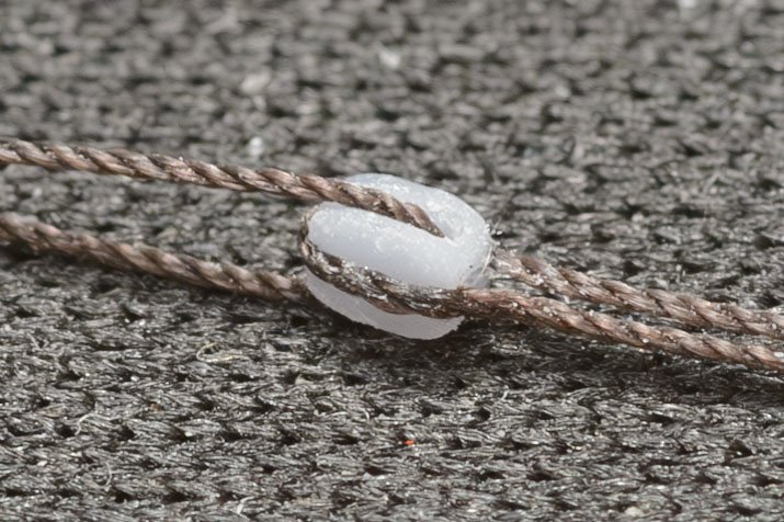
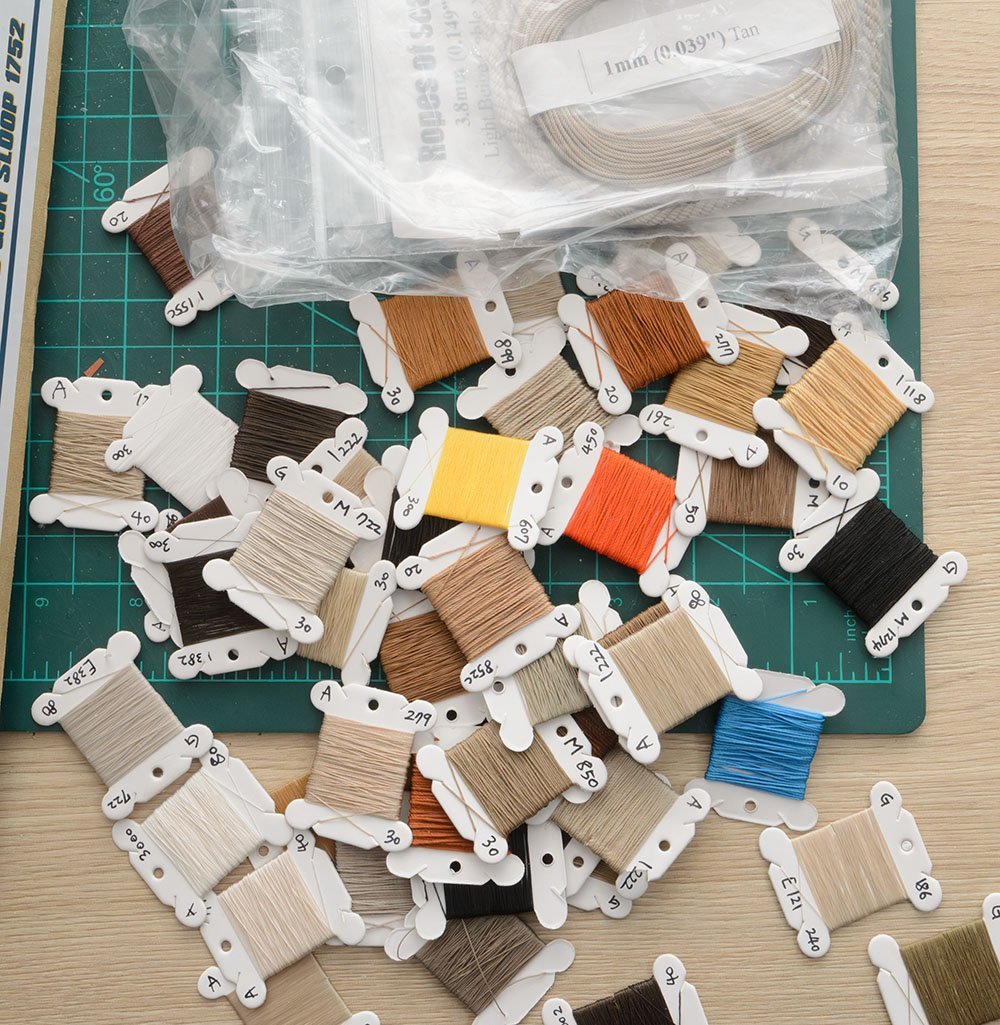
The size of the 3-stranded brown rope is ticket no. 70.
I would say that my new 3D printer is enough to show every detail of blocks above 3.00mm size. All I need is to order black and brown resin.
2.00mm is bare limit, but it doesn't require significant modification.
As I expected, I'm struggling with the 1.00mm block. I'm heavily modifying the 3D block model, and it is getting more and more like a box. I may show the 1.00mm result tomorrow.
-
I really didn't want to come back to this rabbit hole again.
If the blocks must be perfect, the ropes also must be perfect. Before I began making 1mm blocks, I made appropriate ropes using my customized ropewalk. I won't comment on the details of rope now, and will focus on making an 1mm block. Here are today's goal and ropes I made for the blocks.
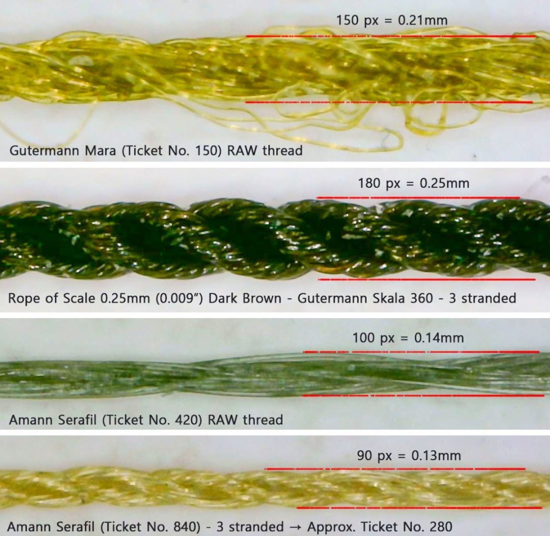
The 4th rope is the thinnest rope I can mass-produce at a low cost. However, it is painful to build the rope, so I don't use it for "fun builds".
Under 0.10mm is a really pricy world. 0.001mm silver wire isn't economical. I have Veevus 16/0 and Uni-caenis 20D mono-filaments, but they are not rope. I'll use these ropes only, so the hole size of the blocks is bigger than 0.13mm.
(Source : https://syrenshipmodelcompany.com/boxwood-rigging-blocks.php )
Next. What kind of block should I make? There are thousands of different types of blocks.
This is a common single block of HMS Bounty. (AotS book, p107) The hole size (black circle) is approx. 25mm or 1 inch.
I made the single block in three different sizes. (2.00mm, 1.00mm, and 0.80mm)
It is digital carving time.
It took 5 hours... I'll print it tomorrow... zzz
-
I'm glad to see you again, Jeff. I'm waiting for your next post.
I used acrylic paint to dye the sails. It's Jo Sonja's Background color series - Linen. I thinned it with water by 1:1. I heard that inorganic paint is stable and has longer life than organic dye.
https://www.amazon.com/Jo-Sonja-Background-Colours-Acrylic/dp/B09P5SYGZV
I experienced that some blocks were not sufficient. (Middle size single block.) I printed them with my 3D printer.
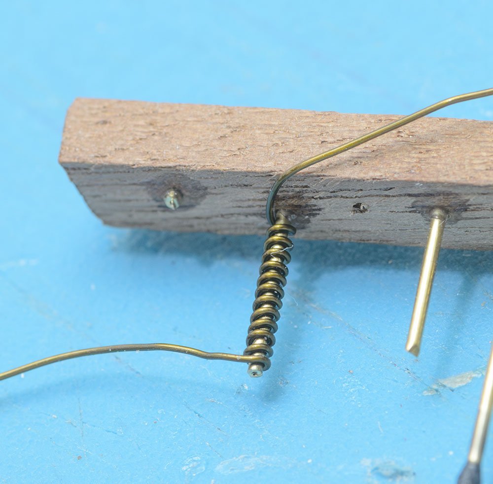
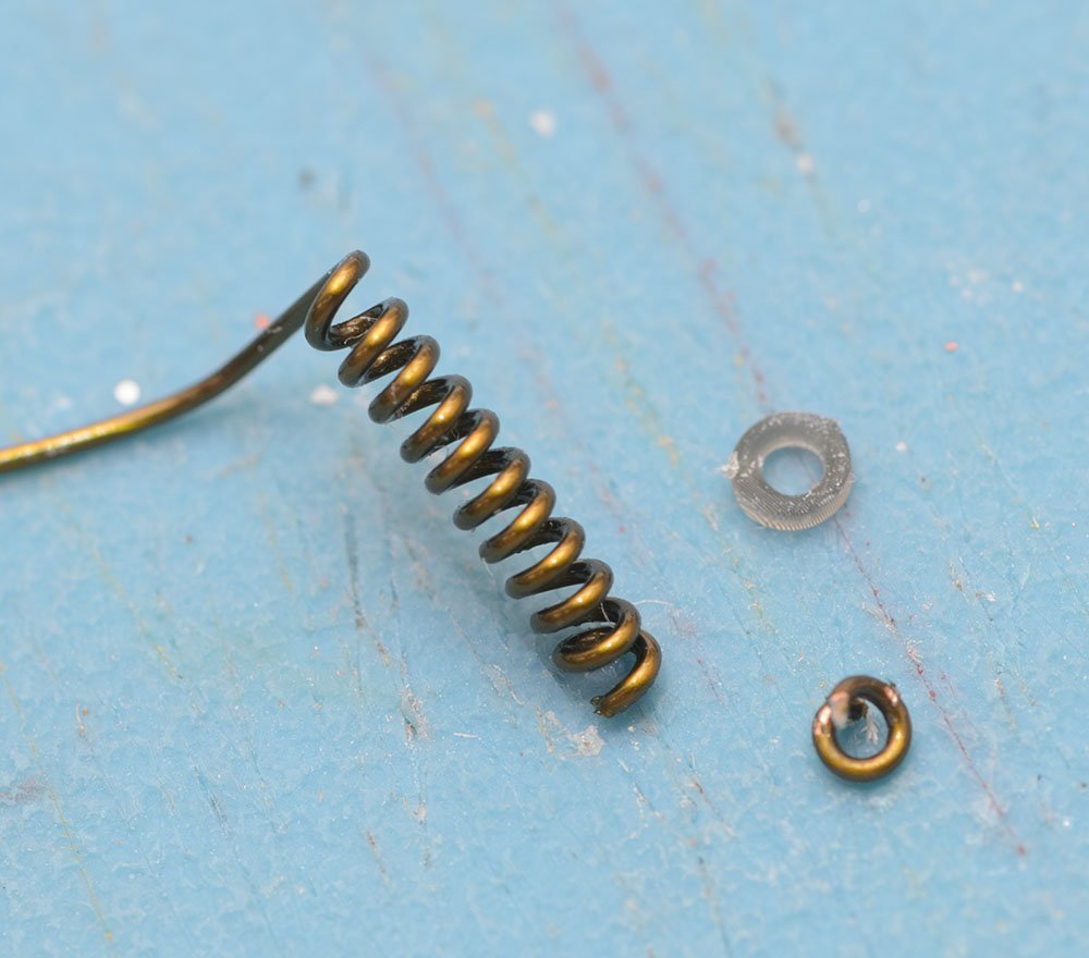
Also, the micro ring is weak. I broke them several times. I finally replaced them with a DIY copper wire ring.
Please watch the instructions carefully. The kit instructions have a few mistakes. Check if the blocks are single or double before seizing them.
-
Thank you so much for leaving a comment, Chris Coyle.
I planned to build the Shipyard HMS Wolf for the next project, but I'm changing my mind to build traditional wooden model kit. I raised expected difficult level and building time of paper kits to the same as for wooden model kit.
Thank you for watching my project, Johnson.
I hope you enjoy your Vanguard Model kits. I'm thinking about whether to open the HMS Alert V3 kit from VM or not.
-
Thank you for enjoying my build log, Grandpa. Also, I thank everyone who's read it so far.
I'm editing video. The video will be uploaded soon.
-
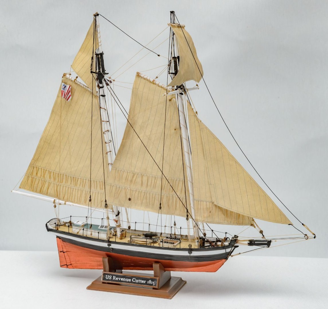


Most paper-cardboard model kits are very professional and delicate. Seahorse makes the best and the most detailed sailing ship cardboard kits. This kit is the most recent kit released last year, and it includes the newest gimmicks, such as 3D printed rigging parts. If you are an experienced modeller, I bet you will learn many new things by building a Seahorse kit.
While this kit's difficulty level is rated as 2/5, this kit is not for beginners or children, in my opinion. I think that average cardboard model kits from Poland are very difficult because they require many skills, like building a wooden ship model kit. I would say that the Seahorse kit is the best for experienced wooden ship modellers. If you want an easier and bigger ship, I would like to recommend the Shipyard cardboard kits. The Shipyard Hanse Kogge 1/72 series are the best to start cardboard kits.
- Knocklouder, VTHokiEE, ccoyle and 2 others
-
5


Was the working shipyard dock's bottom flat or sloped? (18th century)
in Nautical/Naval History
Posted
The diorama and a beautiful painting are really nice examples, Allan.
I turned my chair 180 degrees and picked up the book. The step by step illustrations are really impressive. Thanks for recommendations, Mark P.
I can't imagine how the Great Britain was launched sideways.