Rick310
-
Posts
833 -
Joined
-
Last visited
Content Type
Profiles
Forums
Gallery
Events
Everything posted by Rick310
-
George, congratulations on your new job! Good luck!! Had to laugh when I saw the picture, as I have been on board her! The Mather! Lived outside of Cleveland for 36 years, in Mentor, lake county, before moving to Maine full time in December, 2019! My daughter and her husband still live there. Would love to meet you next time we are in town! Rick
-
Keith, another fun build!! She looks great!! Rick
- 457 replies
-
- 3
-

-

-
- sternwheeler
- Hard Coal Navy
- (and 1 more)
-
Feel better soon Rob! Staghound looks great!! Rick
-
Welcome back Rob! Model looks great! Rick
-
Totally agree Rob. Jared, we all make aesthetic decisions based on what we know and what we think looks good/ correct. I will choose to mount the booms in their irons, the traditional way to display them. Not right or wrong, just personal preference. The model looks great!!! Rick
- 431 replies
-
- 1
-
-
- Flying Fish
- Model Shipways
- (and 2 more)
-
Nice job on the bell and binnacle, look’s really good! your Flying Cloud is coming along nicely!! Check the lengths of your chai plates, in the picture they look a bit long. Rick
- 200 replies
-
- 1
-
-
- Flying Cloud
- Mamoli
- (and 1 more)
-
Rob, thanks for your kind words and encouragement! To answer your question, no, I bend to complete the entire model, all masts, yards and rigging. Rick
- 360 replies
-
- 1
-
-
- Flying Fish
- Model Shipways
- (and 1 more)
-
Thanks Jared, you’re doing a great job on your model also! Rick
- 360 replies
-
- 1
-
-
- Flying Fish
- Model Shipways
- (and 1 more)
-
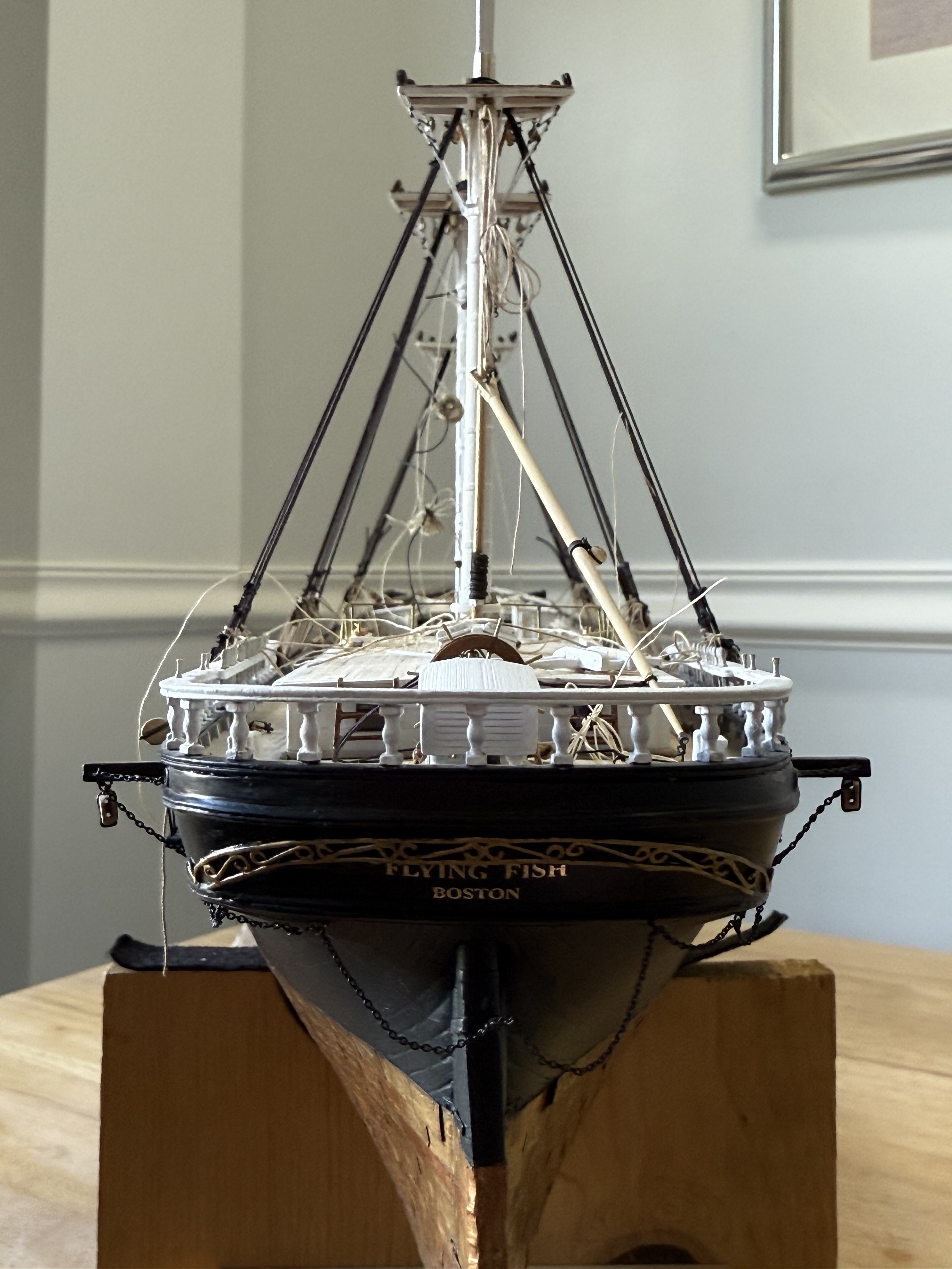
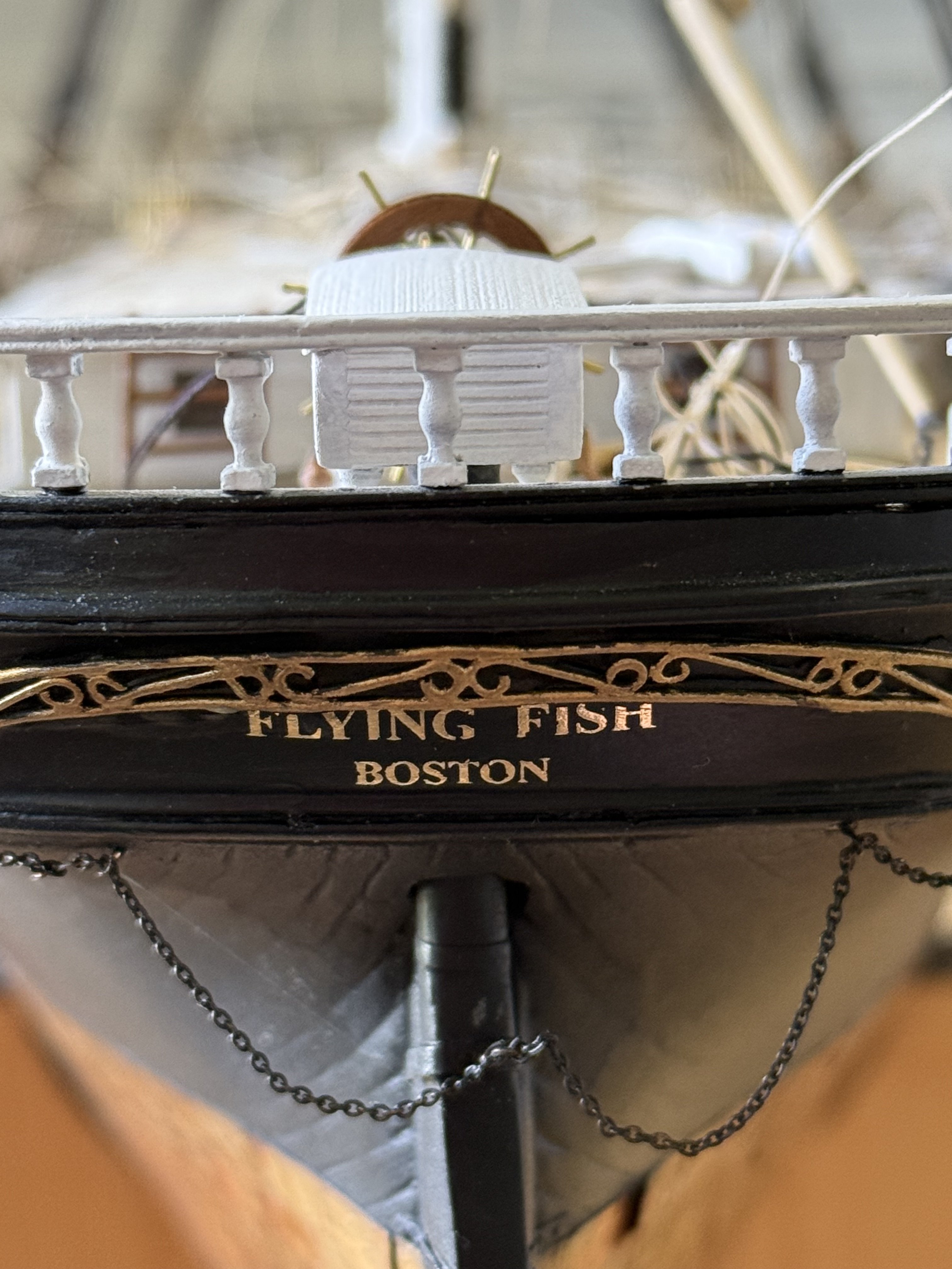
Thanks George and Snug Harbor Johnny! The arch on the stern is pretty crude, but I didn’t have a better idea. No way I could carve it out of wood and no good design for a decal . Rick
- 360 replies
-
- 1
-
-
- Flying Fish
- Model Shipways
- (and 1 more)
-
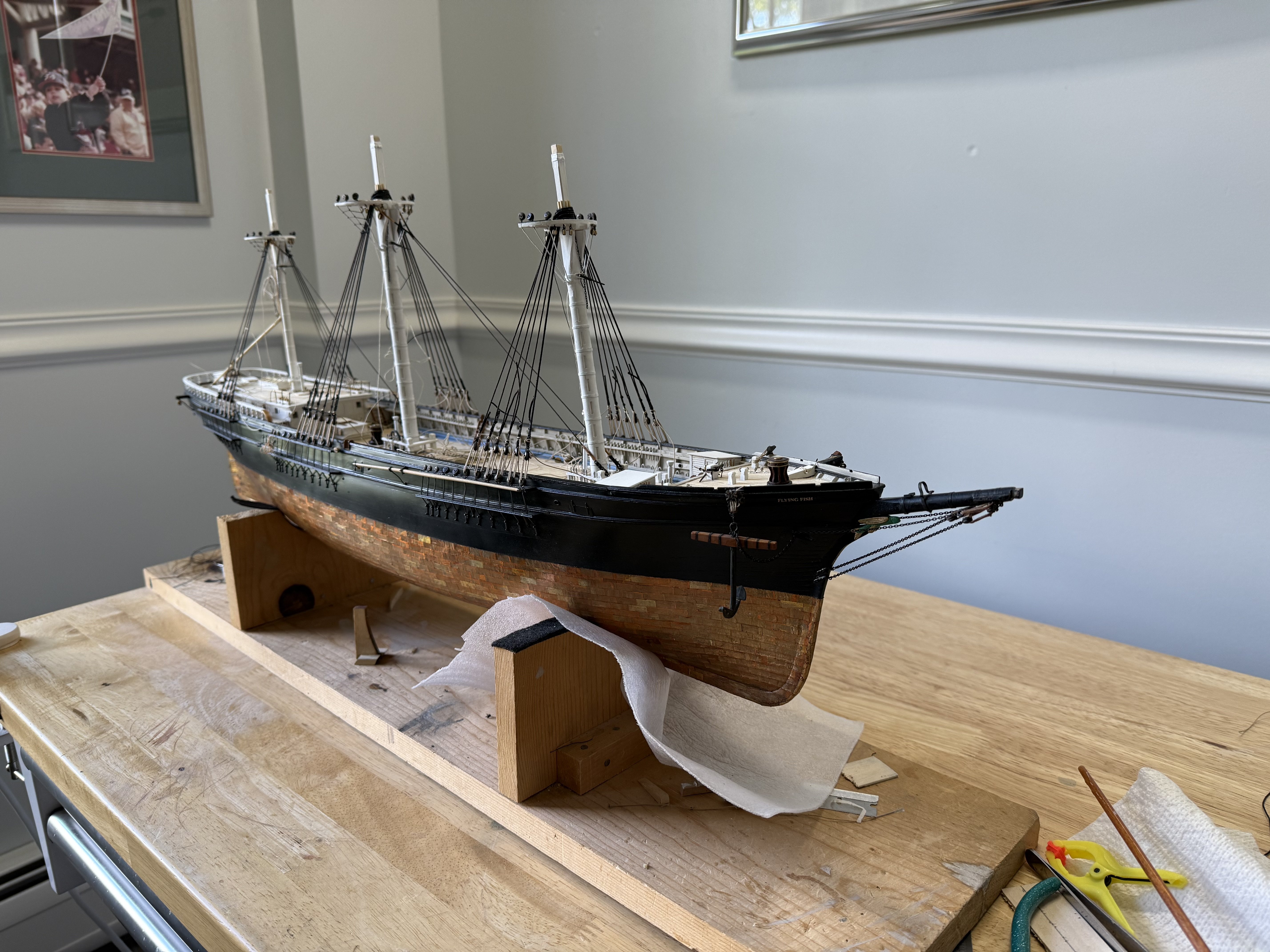
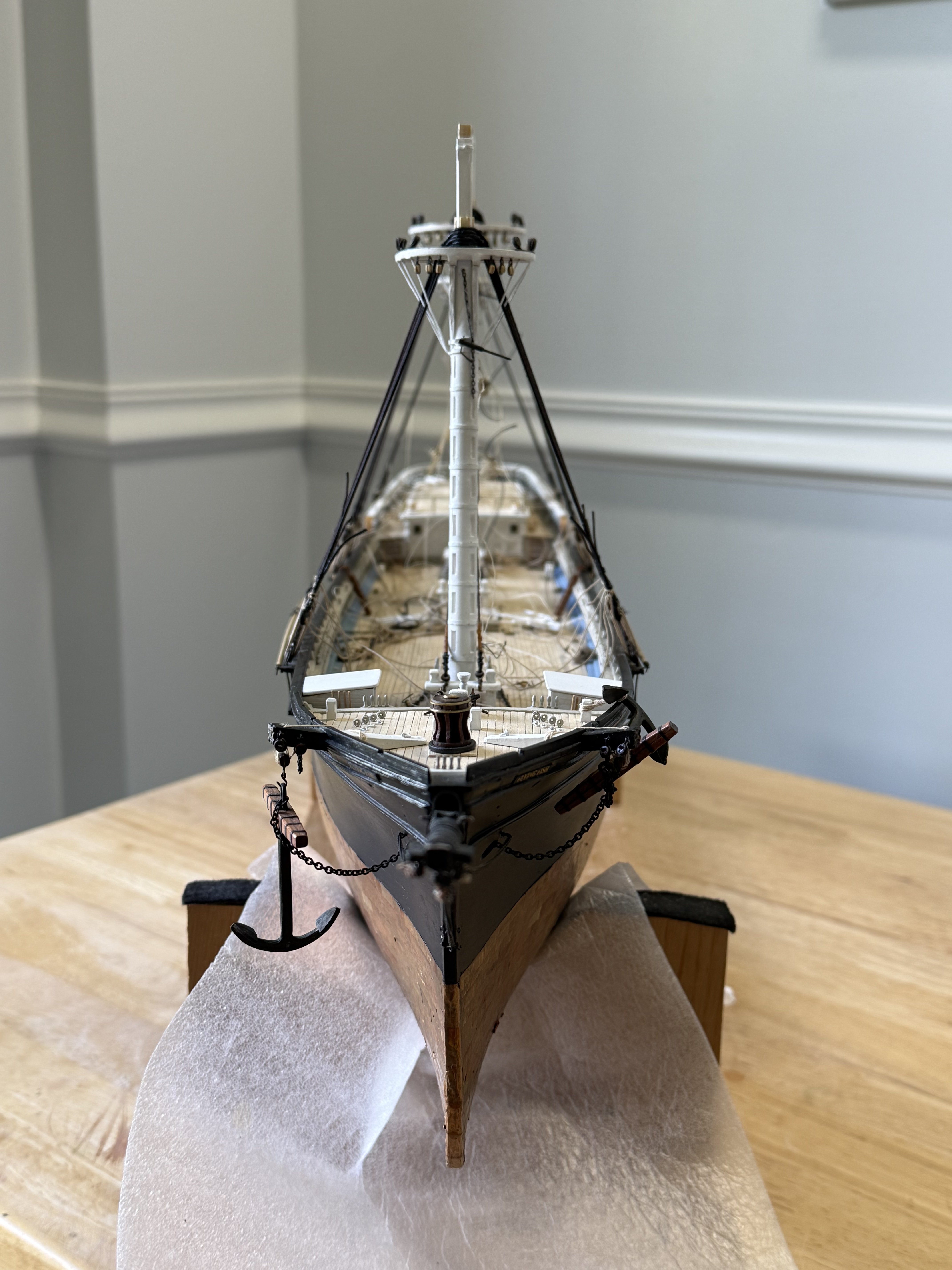
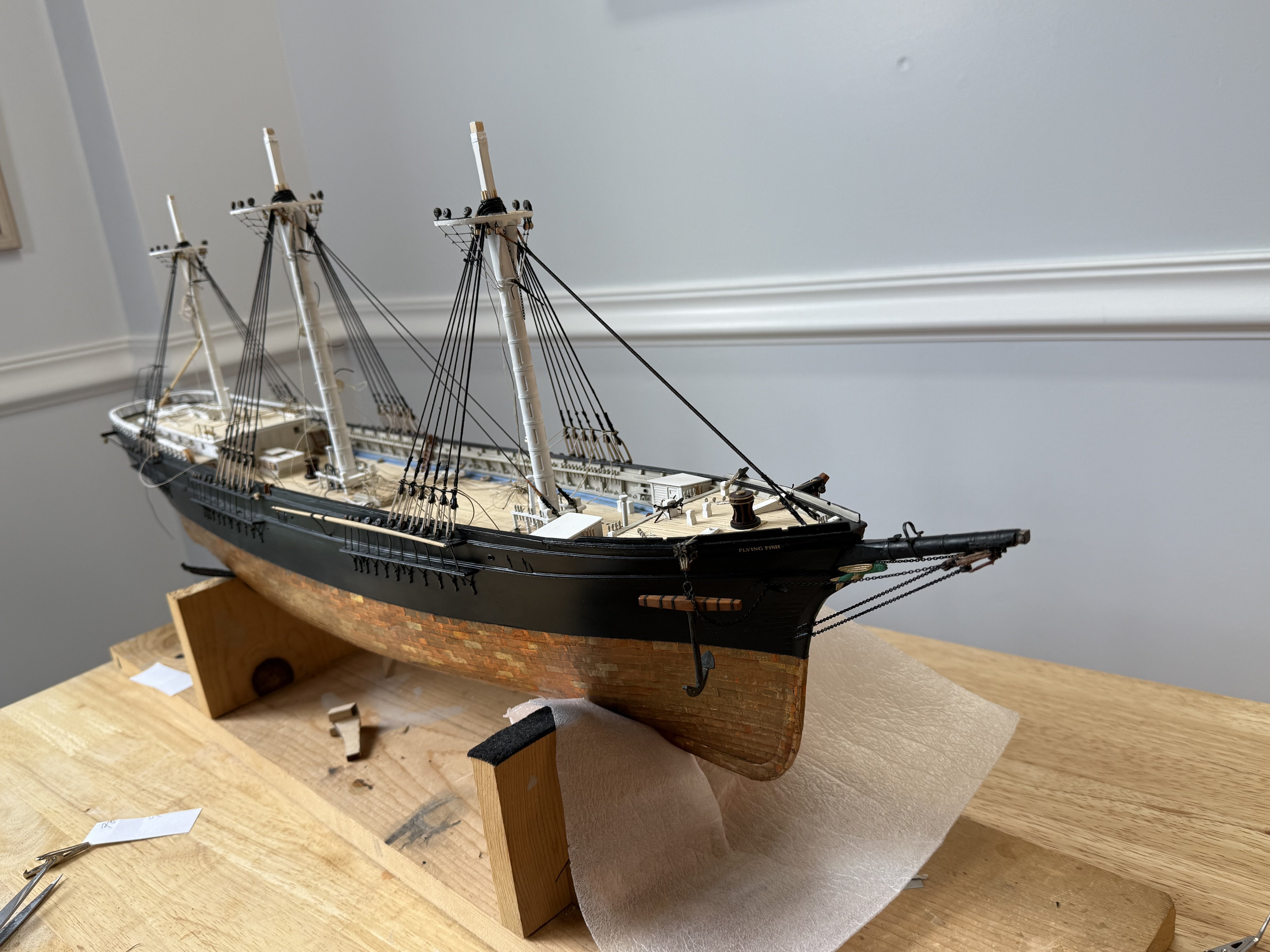
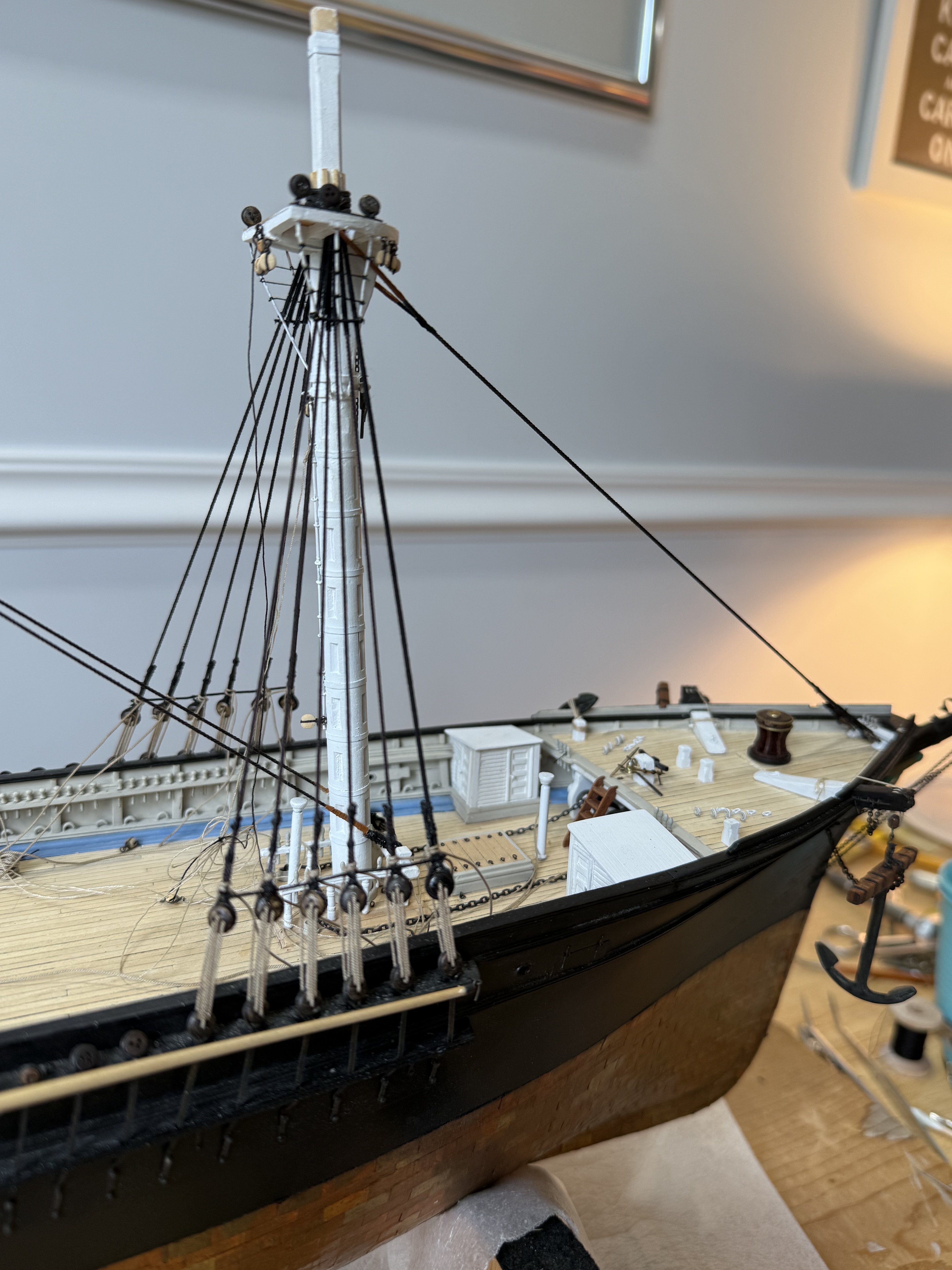
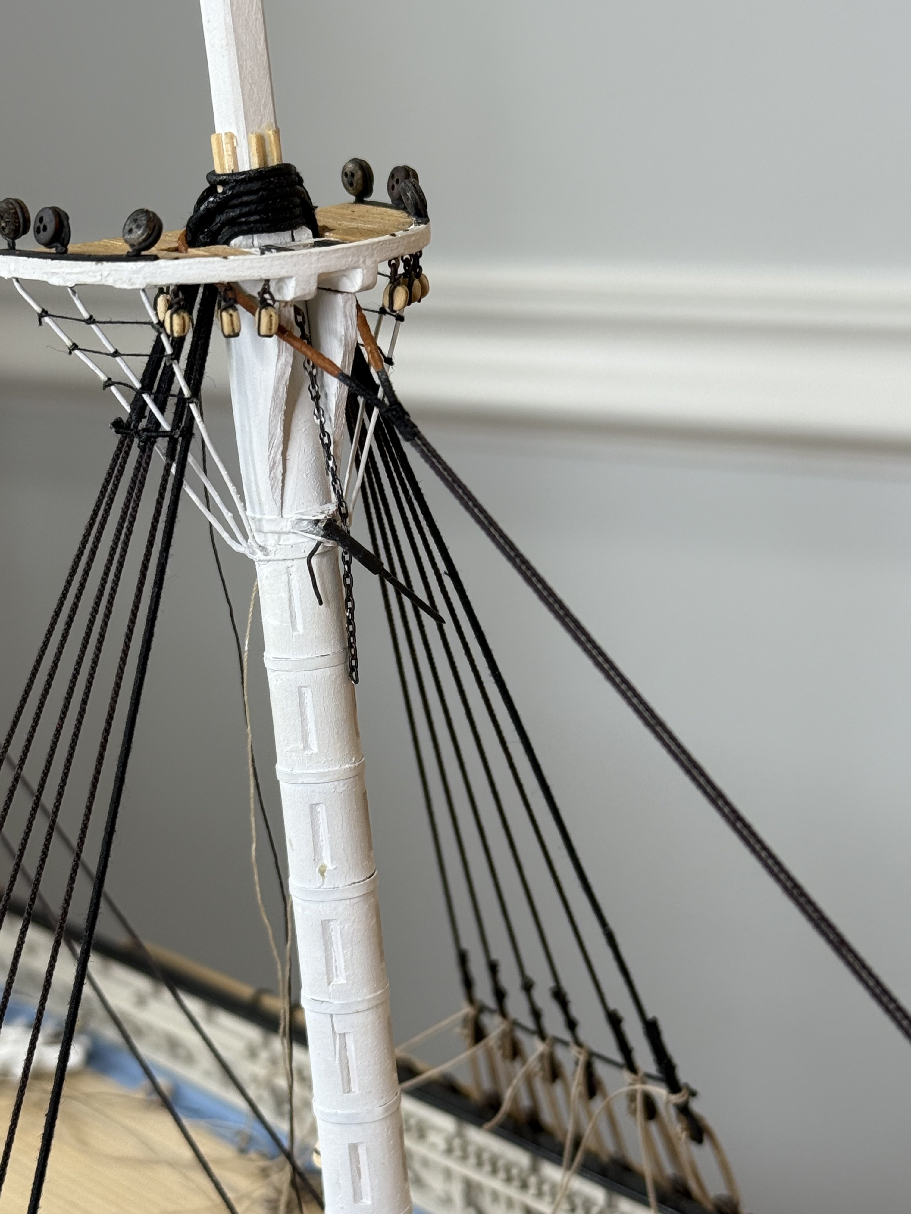
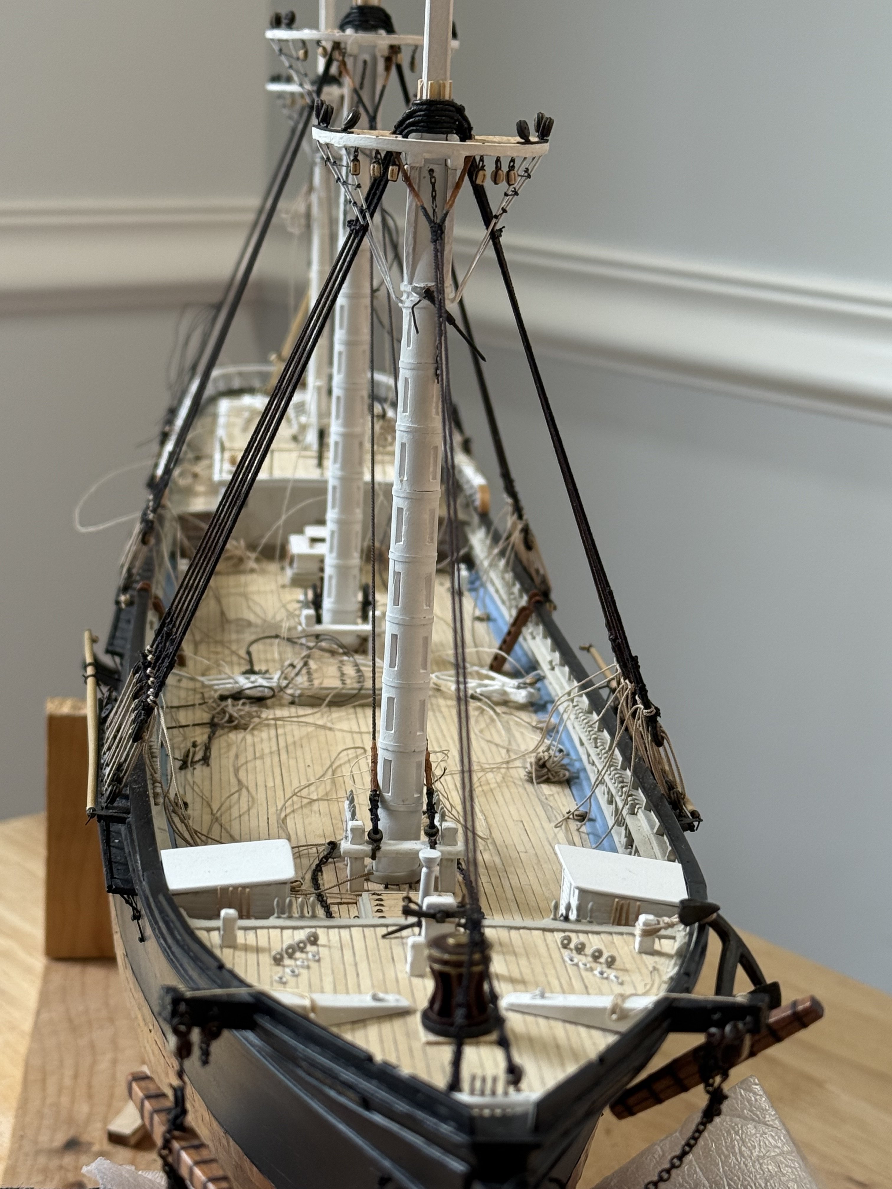
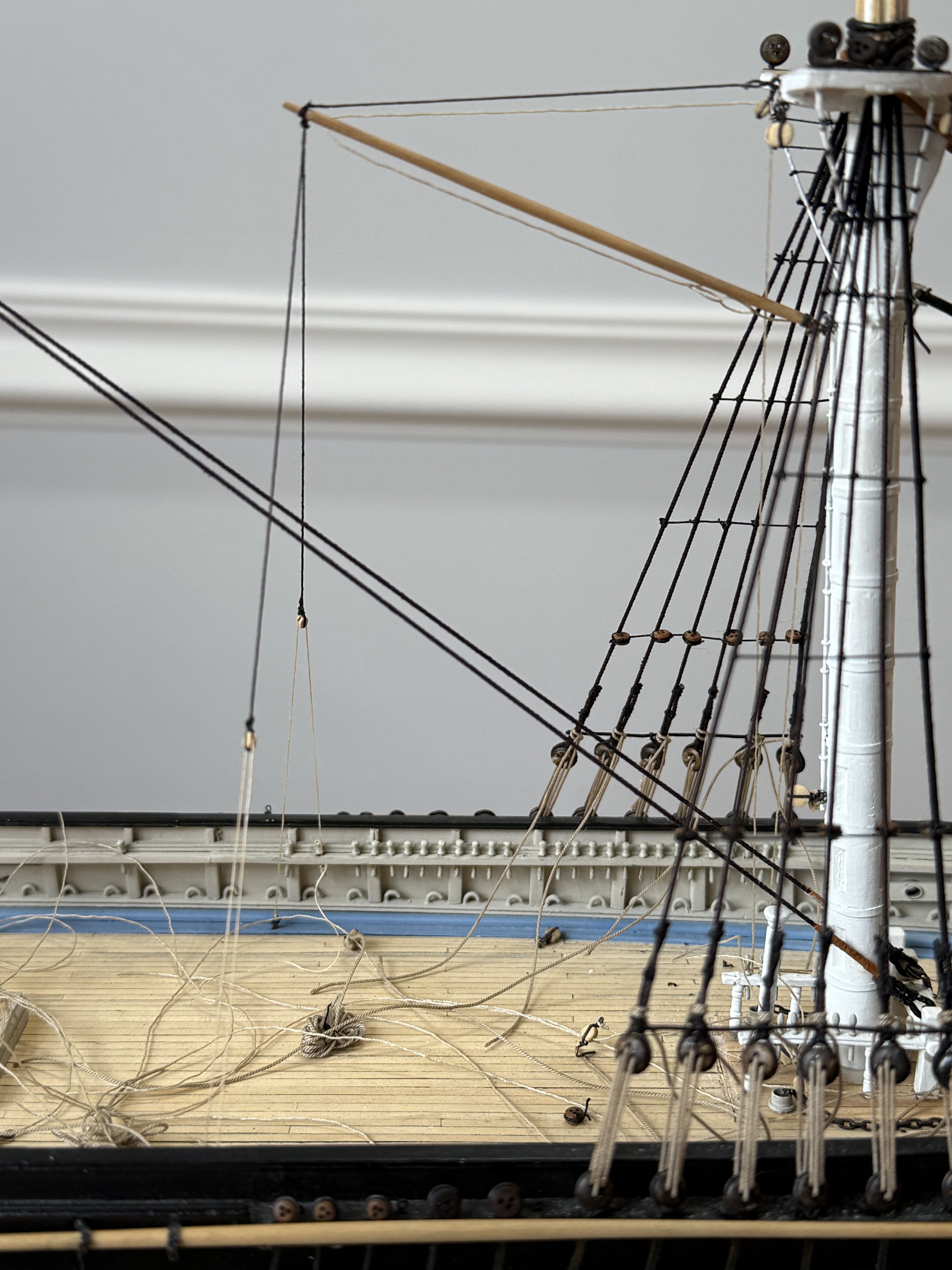
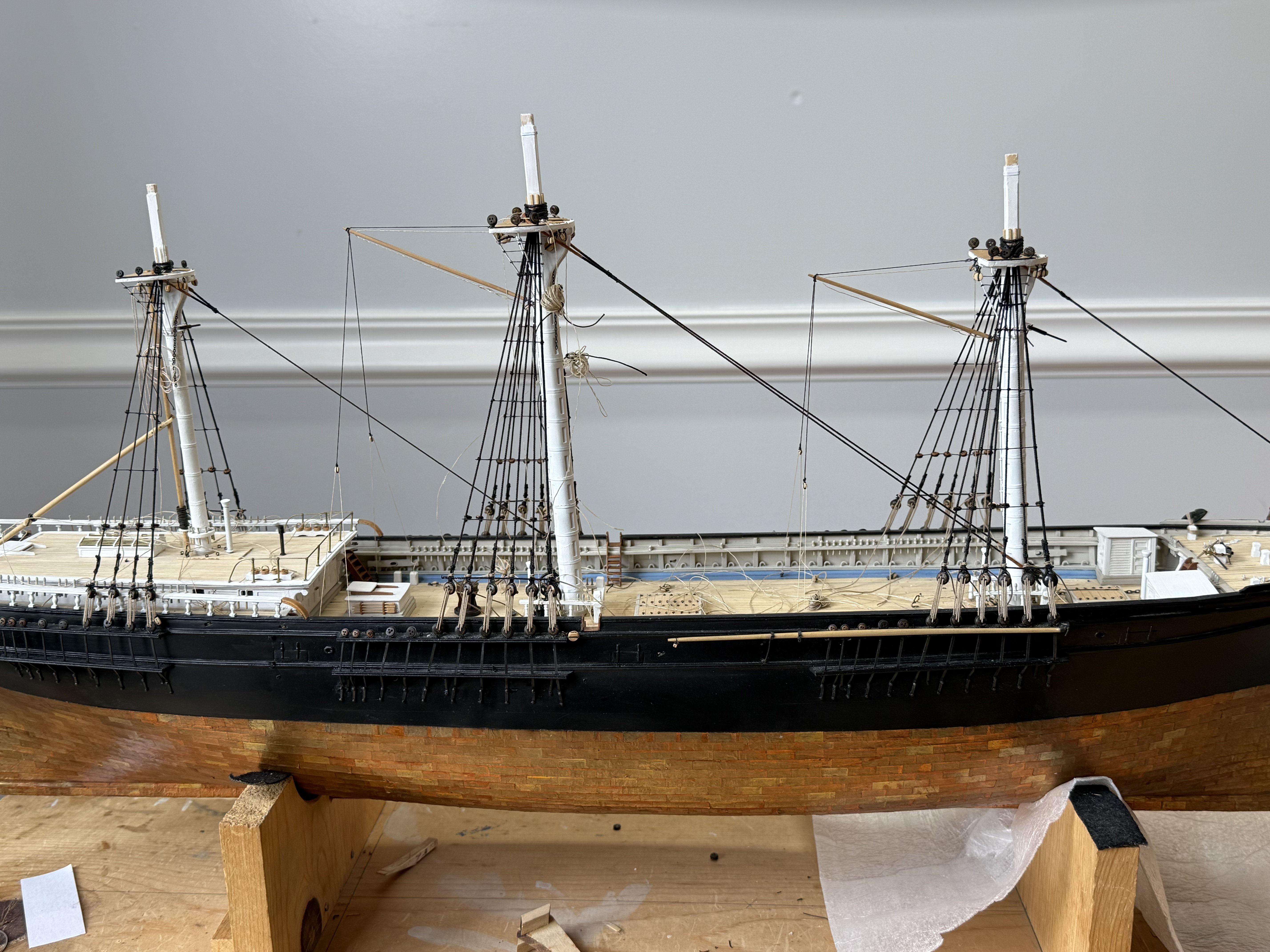
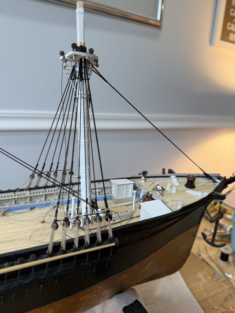
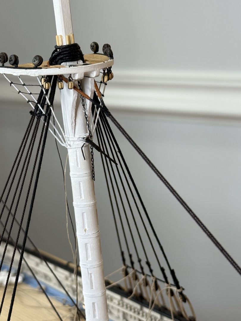
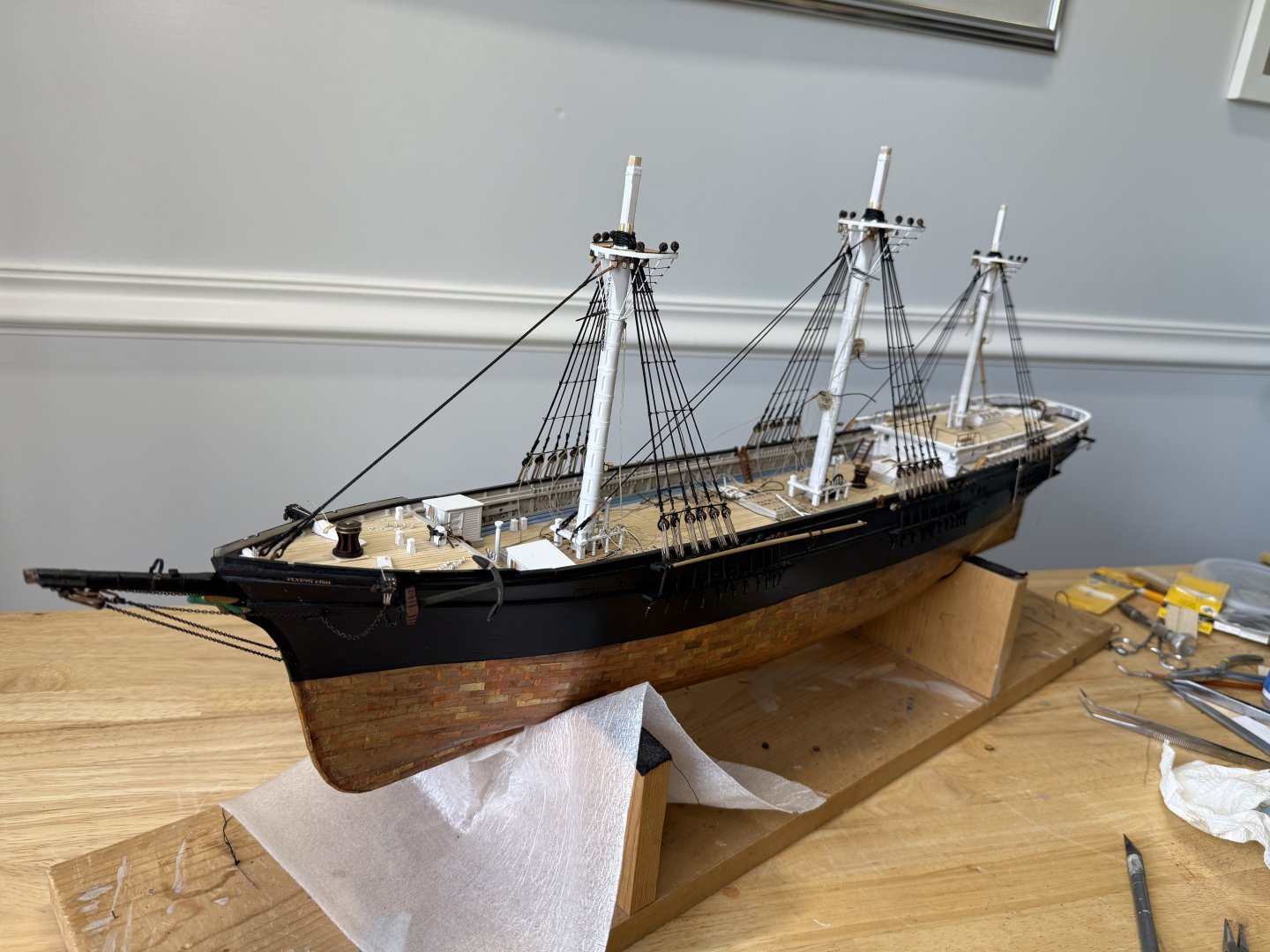
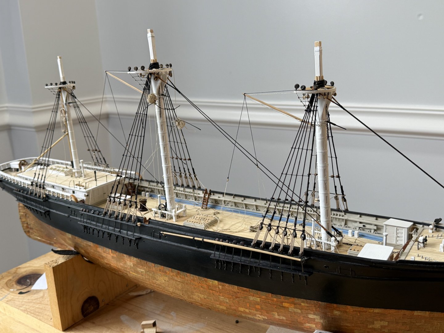
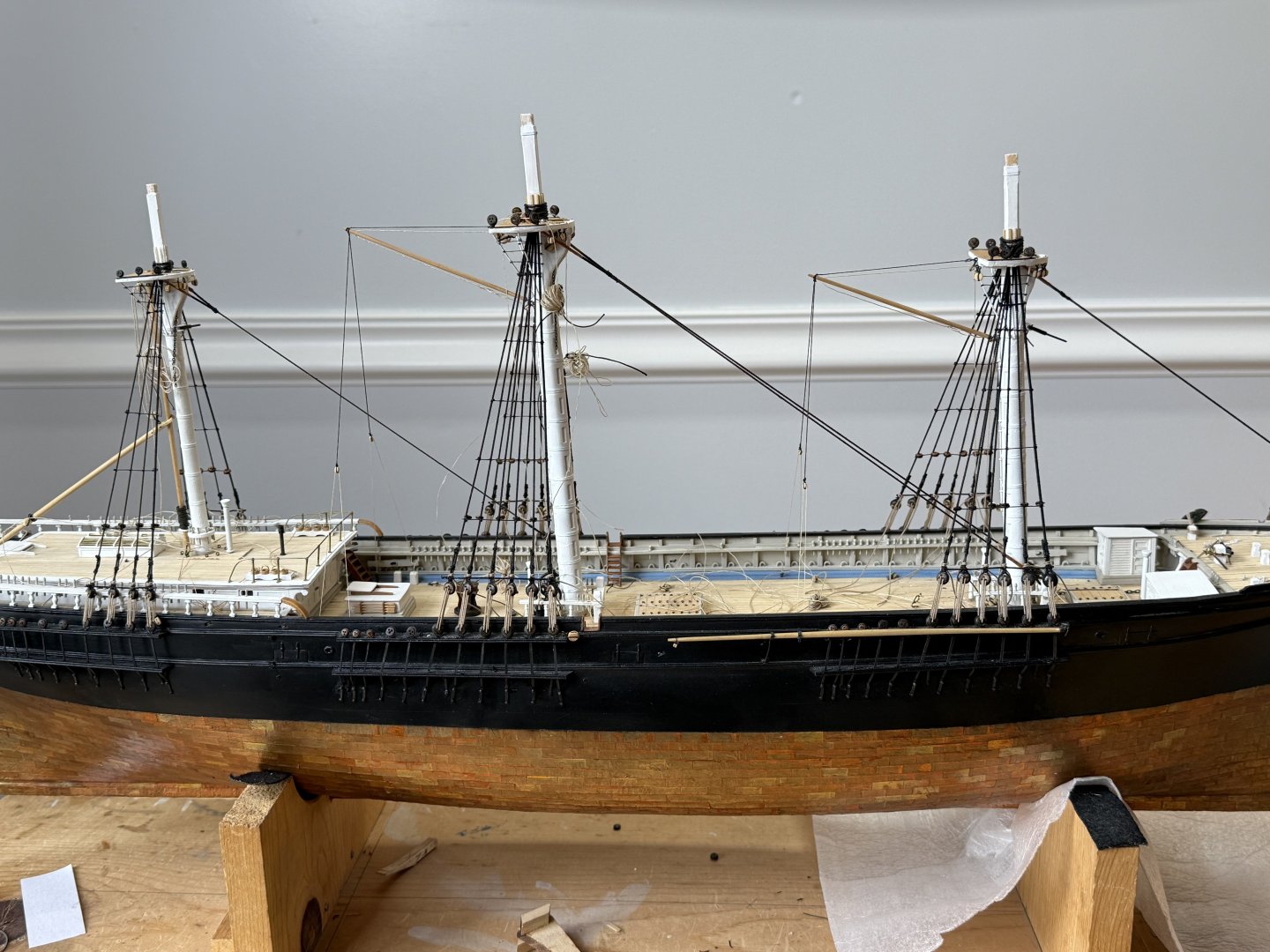
Finished the fore mast shrouds, with serving. parcelling and leather as per the main mast . Took 2 attempts to get the fore stay right. First attempt, I didn’t account for the line stretching, which caused the 2 legs to be misaligned in regards to the serving and leathering. Second attempt came out really well until I noticed that the legs were crossed. This necessitated cutting all 6 seizings which of course damaged the serving , which then had to be repaired. Self inflicted wounds are much too common! Next, placed all the shroud fairleads as per EdT. using 3/32 deadeyes with a groove filed to fit onto the shroud. Finally, placed and rigged both Spencer booms. I included the inhaul/outhauls as I have never seen a model with them on. I tied these together with bowlines as they would have been tied to the head of the sail.


- 360 replies
-
- 8
-
-

-
- Flying Fish
- Model Shipways
- (and 1 more)
-
Jared, I read that the stuns’l booms were tied off to the chain slings to get them out of the way when the sails were furled, just as Rob suggested. At sea, sails would not be furled, but they would be reefed. What then? Can’t imagine man handling those booms at sea so the sails could be reefed. Rick
- 431 replies
-
- 1
-
-
- Flying Fish
- Model Shipways
- (and 2 more)
-
WOW!! Rick
-
Looking really good Rob!! Rick
-
Congratulations!! Model looks great!! Well done!! Rick
- 144 replies
-
- 3
-
-
-
- Harriet Lane
- Model Shipways
- (and 1 more)
-
Thanks Rob! Great idea for the vent flange! Rick
-
Beautiful work Rob! What spacing did you use for the belaying pins? Rick
-
Beautiful!! I would be completely lost building the Flying Fish if not for EdT’s fabulous books on building the Young America! Thanks again Ed!! Rick
- 3,618 replies
-
- 1
-
-
- young america
- clipper
- (and 1 more)
-
Not fun Rob! Get better soon !! Rick
-
Rob, that was supposed to be very nicely done! Love the trail boards! Just love AutoCorrect!
-
She is really coming along Rob!! Very nicely e!! Love the traitors!! Rick
-
Beautiful! Rick
-
Jared, just got home after being away for 12 days and the shrouds are still taut, although I will need to tighten the mizzen shrouds a bit at some point. Passing the line through the dilute white glue solution and stretching them as they dry, seems to have worked well, as I had a dehumidifier running the whole time I was gone. Rick
-
Glad to know you are OK Keith! Looking forward to you getting back to the ship yard! Rick
-
Jared, for what it’s worth, I’ve been dragging my line through a dilute solution of white glue and then hanging it with weights to stretch while drying, both running and standing rigging. Don’t have enough running rigging to tell yet, but hopefully the shrouds on the mizzen and main masts will stay relatively tight. Been gone for last 10 days, so I will check when I get home tomorrow. I anticipate having to adjust the lanyards, but hopefully not too much. One issue is the change in humidity, high humidity, lines swell and tighten up, dry humidity and line go slack, as I understand it. The solution of white glue is supposed to protect the lines from moisture. Running the lines through wax is supposed to do the same thing. Rick
-
Just a beautiful hull form Rob!! Great job!! Rick