DONATION DRIVE - SUPPORT MSW - DO YOUR PART TO KEEP THIS GREAT FORUM GOING!
×


Richard44
-
Posts
429 -
Joined
-
Last visited
Content Type
Profiles
Forums
Gallery
Events
Everything posted by Richard44
-
I came across this website which sells card for models - there may well be other sites as well. https://papermodeling.net/index.php?route=product/category&path=79_86&page=2 Edit. Found another. https://modelik.pl/tektury-astralon-c-101.html Cheers
-
 Didn't know that. But every 3 view I could find showed no sweepback at all. Maybe designed that way but later built with no sweepback as was easier. Edit. A side view in "Jane's All the World Aircraft 1919" (facsimile copy) suggests that there is no sweepback. The root and tip chords are shown for both wings. Unfortunately no wing plan. Cheers
 -
Chris, As usual, I'm thoroughly enjoying your superb build. However, the lower wing seems to have a small amount of sweepback. Is this intentional? Cheers
-
And happy holidays to you too Allan! I've used Casey Brass Black in the past with mixed success. I've cleaned the brass etc etc, used the solution diluted, but it doesn't always seem to work. I suspect the composition of the brass has something to do with it. Perhaps too much zinc relative to copper. Cheers
- 36 replies
-
- 2
-

-
- Shallop
- Pavel Nitikin
- (and 1 more)
-
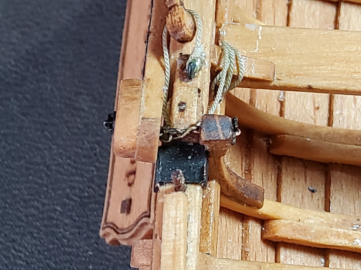
Chuck, Here's the close-up. You can see the chain, and if you look carefully, you can see the retaining pins at each end. The leeboard doesn't flap around as much as you might think as the lifting tackle restricts it somewhat. Still, it's definitely not fixed and moves easily if touched. I used paint on the iron work - I've never had much luck with using chemical blackeners. Cheers

- 36 replies
-
- 4
-

-
-
- Shallop
- Pavel Nitikin
- (and 1 more)
-
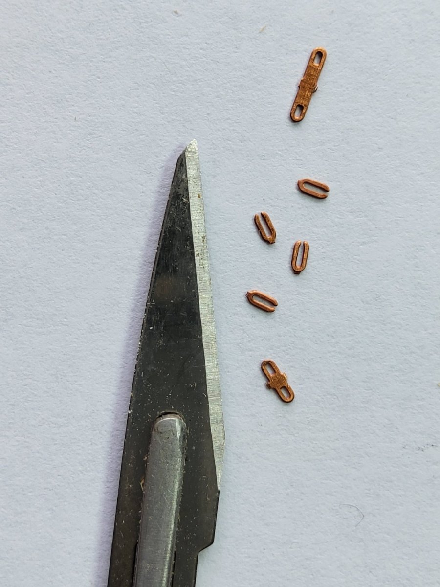
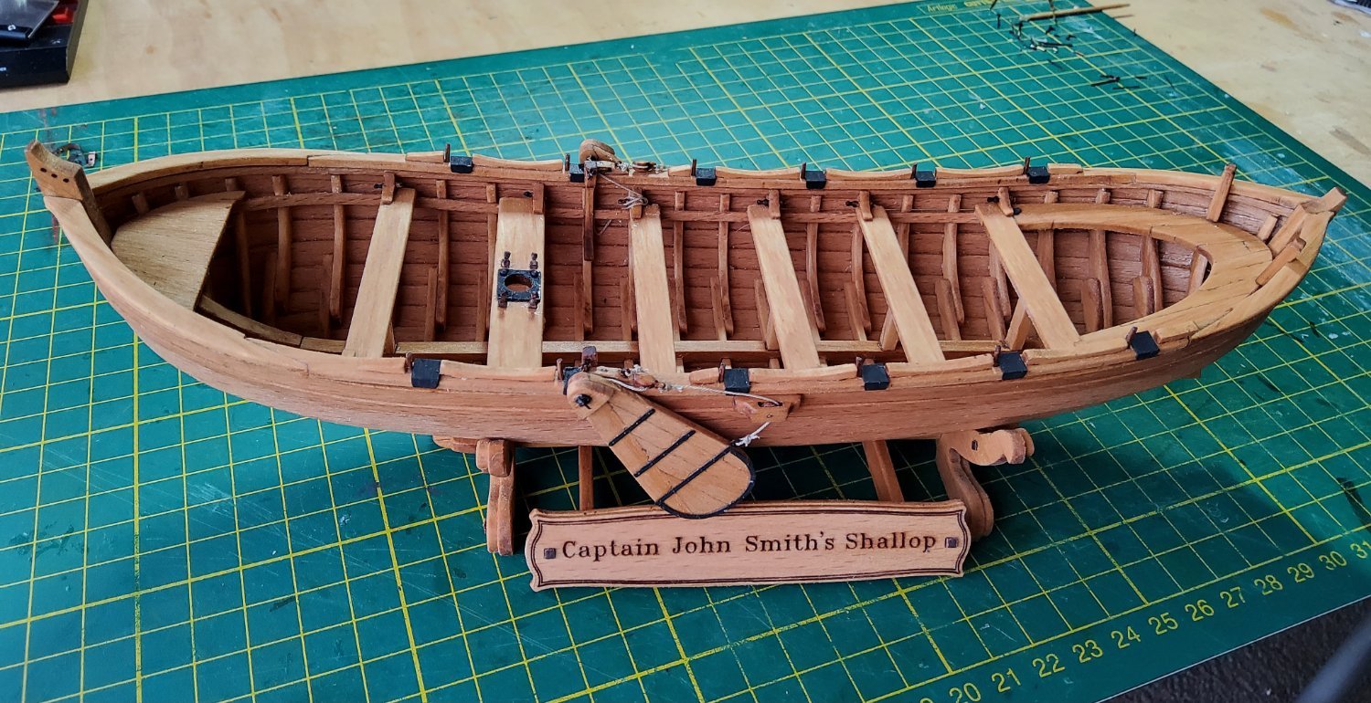
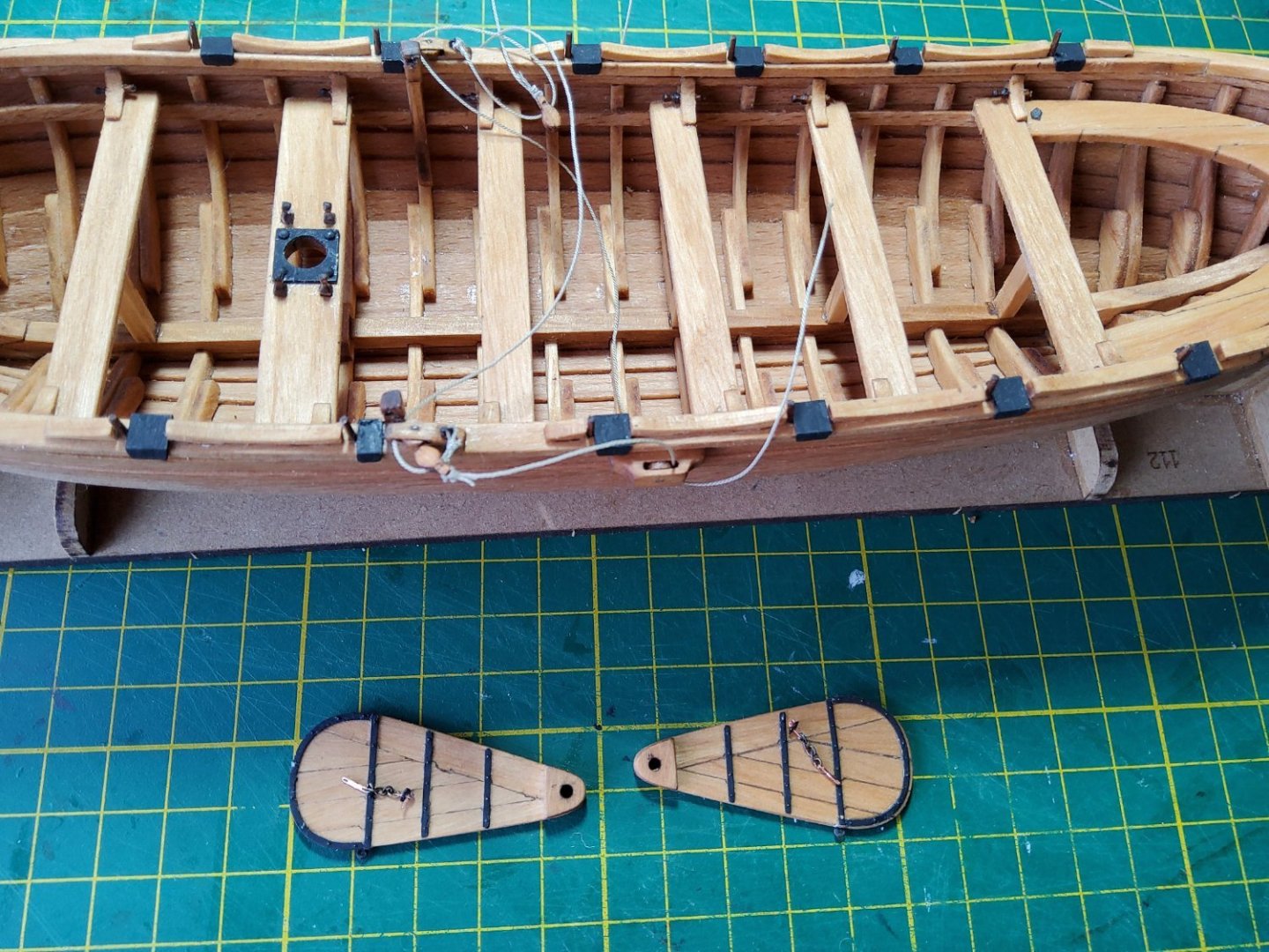
Thanks guys, for the discussion about the leeboards. I'm going to go with what the kit suggests, and hang them from chains. The leeboards themselves were easy enough to assemble, all the parts were pre-cut. The iron reinforcing bands needed a little care to position them, but no dramas. The chains though. These are supposed to be made up using the supplied PE. And these bits are tiny! I didn’t like my chances. Sure enough, "ping" and one piece headed into the clutter on the table - found it though. But, a few minutes later "PING" and this time the piece flew off probably with enough speed to embed itself in the wall - never did find it. I had some chain that was close to the size required, except the links were round not flat, but this was what was going to be used. I had managed not to lose the tiny end plates that go through the leeboard and the inboard support, so got those onto short lengths of chain. Before fitting the assemblage onto the boat, I thought that putting the tackle for raising the leeboards in place would be useful to do now. The photo shows the tackle loosely in place and the leeboards with the chains lying on them. The leeboards were fitted in place with the chains passing through them and the inner ends passing through the inboard supports. Tiny retaining pins (supplied PE) were pushed through the end plates to keep everything in place. Now, as the leeboards are basically just hanging off the chains, they are very vulnerable to damage - don't ask 😖 - and the chains are the weakest link 🥴. Sometime later, when repairs had been made and calm restored, I completed rigging the tackle. It looked good. Then I thought I should put the boat onto the display base and promptly found that I hadn't tightened the tackle enough, as a result of which the leeboards hung too low and fouled the base 😬. The tackle would have to be redone. Not a big deal, but a nuisance anyway, and after a few deep breaths, I tackled the tackle to get it right. Cheers

- 36 replies
-
- 9
-
-
-
- Shallop
- Pavel Nitikin
- (and 1 more)
-
Hi Robert, You're doing well, it's looking good. You'll catch me shortly 🙂. Cheers
-
Hi Robert, Interesting video. Thanks for that. Not sure of the difference between his two types of leeboards - "normal" and "other". Though it seems from what he was saying his "other" only swings fore-and-aft, whereas his "normal" is free to swing fore-and-aft and also pivot so that it rises near horizontal. The method of rigging the leeboards on the model (and presumably the replica), using a chain that is only fastened to the hull in-board, suggests that this would allow the leeboards to swing in the guy’s "normal" fashion. The chain would be flexible enough to allow this. Cheers
- 36 replies
-
- 3
-
-
- Shallop
- Pavel Nitikin
- (and 1 more)
-
Hi Chuck, You've just managed to comment on exactly the same concerns I have about the leeboards. I don’t think you've missed anything that's shown on the plans. I've been puzzling over them for the last day or two (Olha's video doesn't help at all). I may have them rigged today or tomorrow. Cheers
- 36 replies
-
- 2
-
-
- Shallop
- Pavel Nitikin
- (and 1 more)
-
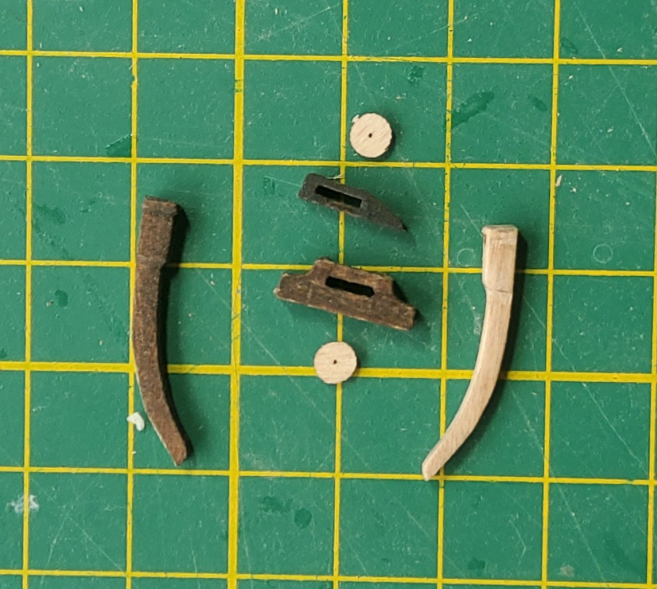
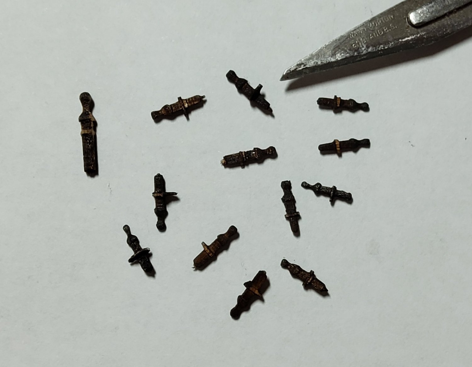
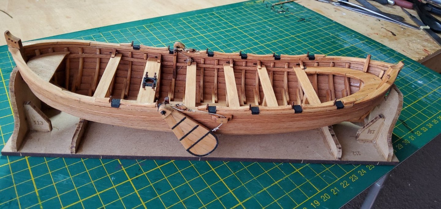
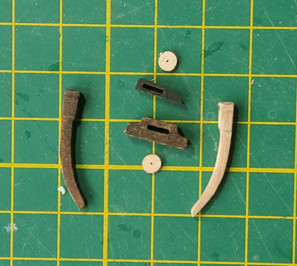
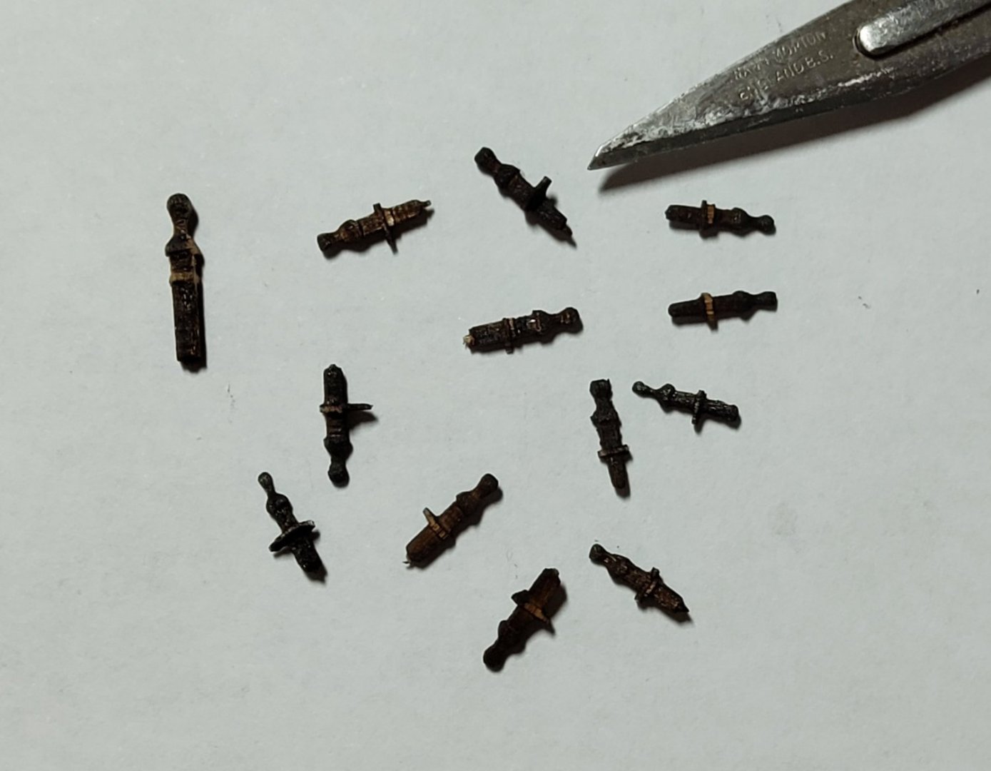
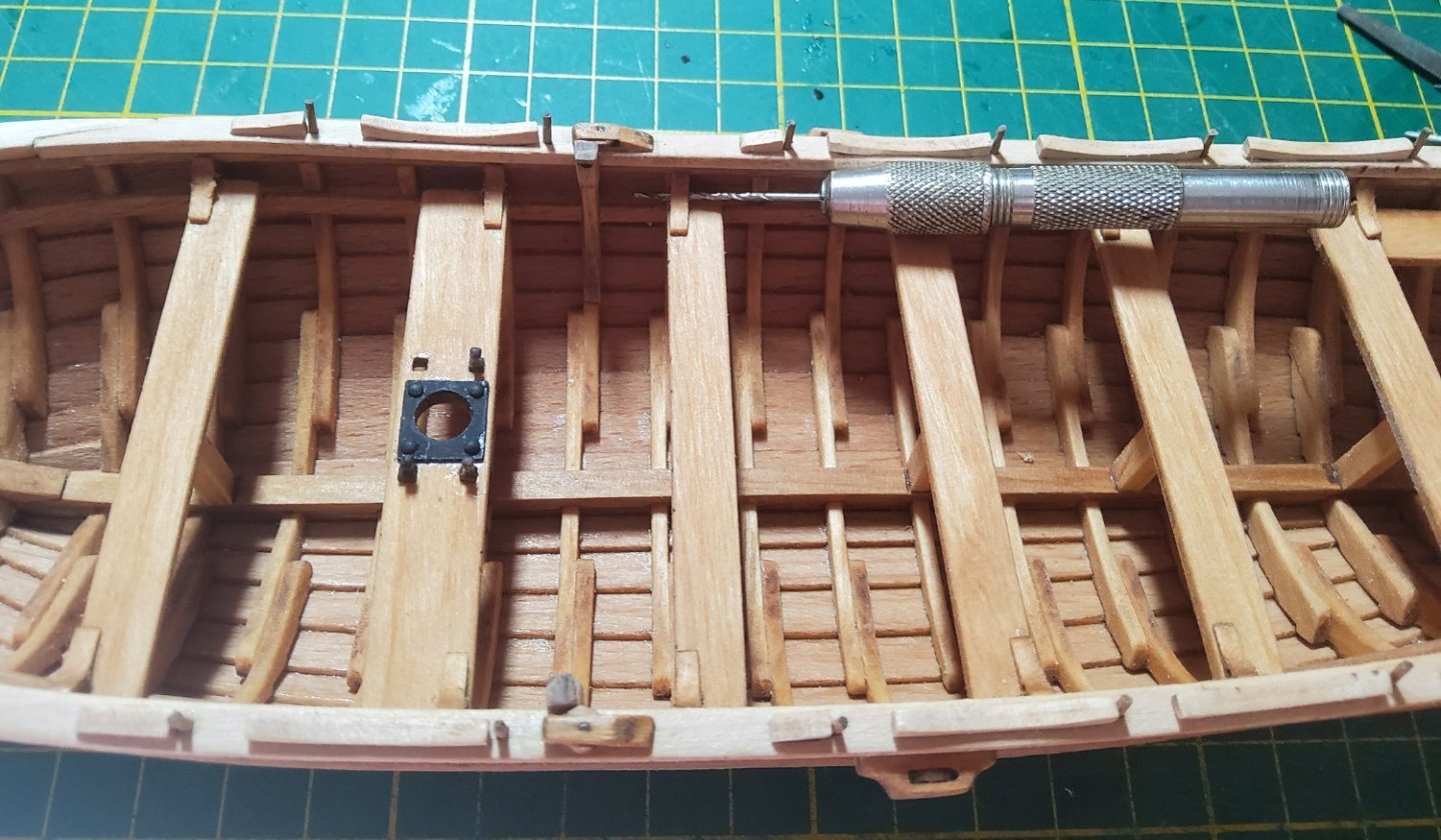
Thanks for all the views, likes and comments. The basic hull is now finished. And I should have mentioned before that I'm using Tung oil on the model. Splashboards (I think that’s what they are), thole pins, belaying pins around the mast position and the supports and sheaves for the leeboards are all in place. The supports (no idea what they're actually called) for the leeboards, one clean, one not, and two of the four sheaves that are yet to be assembled. Simply a matter of sliding the "wheel" into the housing. There are more belaying pins that go through the knees on the thwarts, but they're not really visible - they are only tiny. They all needed cleaning to get rid of left over bits from the laser cutting. The larger pin on the left goes into the thwart next to the mast. One thing I forgot to do was clean out the lasercut holes in the knees before gluing them in place, so they were now cleaned very carefully with a partly disassembled pin-vise. The supports for the leeboards were a bit of a problem, my fault for not examining the plans closely enough. I initially glued them so their tops were in line with the top of the sheave that is next to them on top of the rail. This can be seen in the above photo. Wrong. Their tops have to be slightly higher as the chain that passes through the support to the leeboard has to clear the top of the sheave (this will be clear once the leeboards are in place). They were therefore de-glued and repositioned. The supports are glued to the frame and notched to go over the stringer that the thwarts rest on. Or, as I did, notch the stringer rather than the support as this was easier. There are also metal wear plates, I'd guess you'd call them, on the rail next to the thole pins, presumably to protect the rail from the oars. These were copper PE and went into position easily except for the two that are next to the leeboard support/sheave. Not enough space, short by a few mm. Can't move the thole pin and can't move the sheave/support, so had to trim the plate. The next stage will be the masting, leeboards, rudder etc etc. Cheers
- 36 replies
-
- 8
-
-
- Shallop
- Pavel Nitikin
- (and 1 more)
-
Good morning. You've already put pieces 128 onto the hull (or at least some of them) - they're the timberheads, and are shown on one of the ply sheets on Sheet 2. Piece 288 is a strip of white metal. Both pieces are identified in the list at the end of the manual. Keep going, you'll have a very nice model when you've finished. Cheers
- 261 replies
-
- 4
-
-
- Victory Models
- Pegasus
- (and 3 more)
-
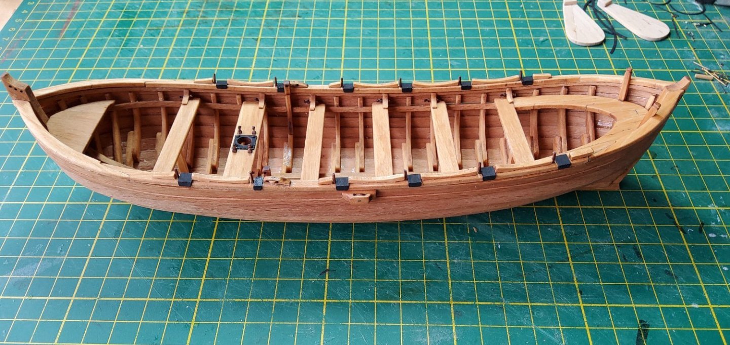
Thanks for all the comments and the likes. In particular the discussion about whether or not Smith’s shallop was clinker (lapstrake) or carvel built was interesting. However, the kit is clinker so that's what this shallop shall be. 🙂🥴 The caprail has been added. This is in three pieces and the instructions suggest that it be glued together before fitting to the hull. I didn't like this idea so decided that I would fit it piece-by-piece on the hull. I did a dry fit and found, not unexpectedly, that the rail needed a little bending to conform to my hull. Otherwise the fit was near perfect. So the central piece was soaked then bent against a template formed by tracing the outline of the hull, with nails (in a board) to hold the rail in place until it dried. The forward piece of the rail was first glued in place, then the centre piece and finally the aft piece. Cheers

- 36 replies
-
- 5
-
-
- Shallop
- Pavel Nitikin
- (and 1 more)
-
Thanks for that Chuck. Cheers
-
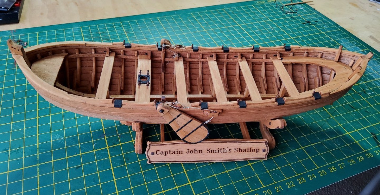
Hi Allan, Thanks for that info. The kit will still build up to a neat little model, but maybe I'll omit the nameplate that says "Captain Smith's Shallop". 🙂 Cheers
- 36 replies
-
- 1
-
-
- Shallop
- Pavel Nitikin
- (and 1 more)
-
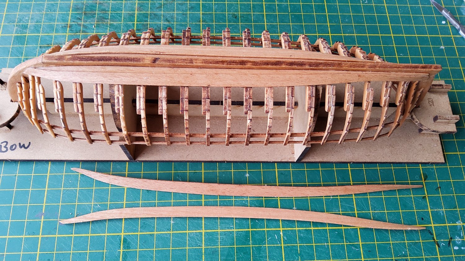
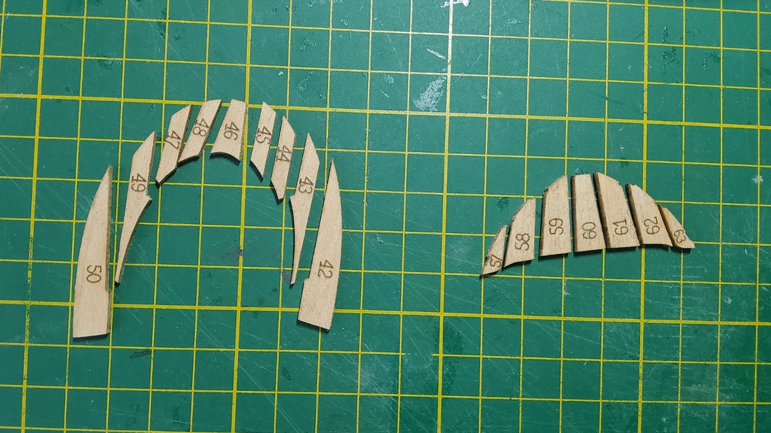
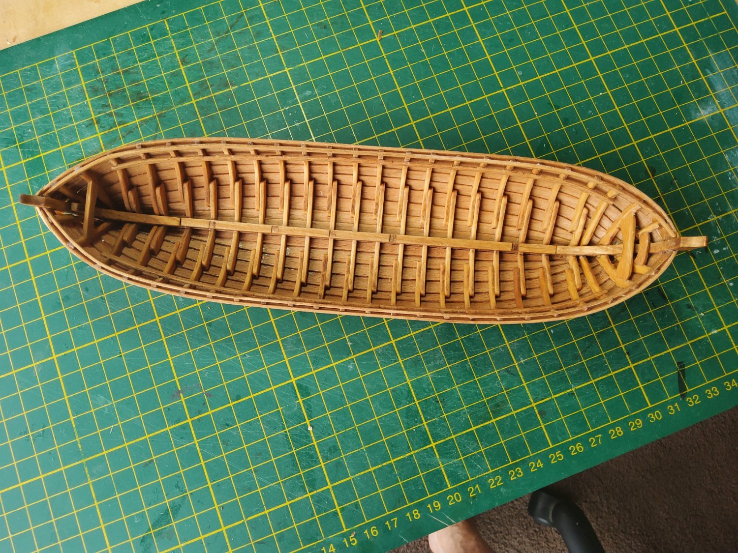
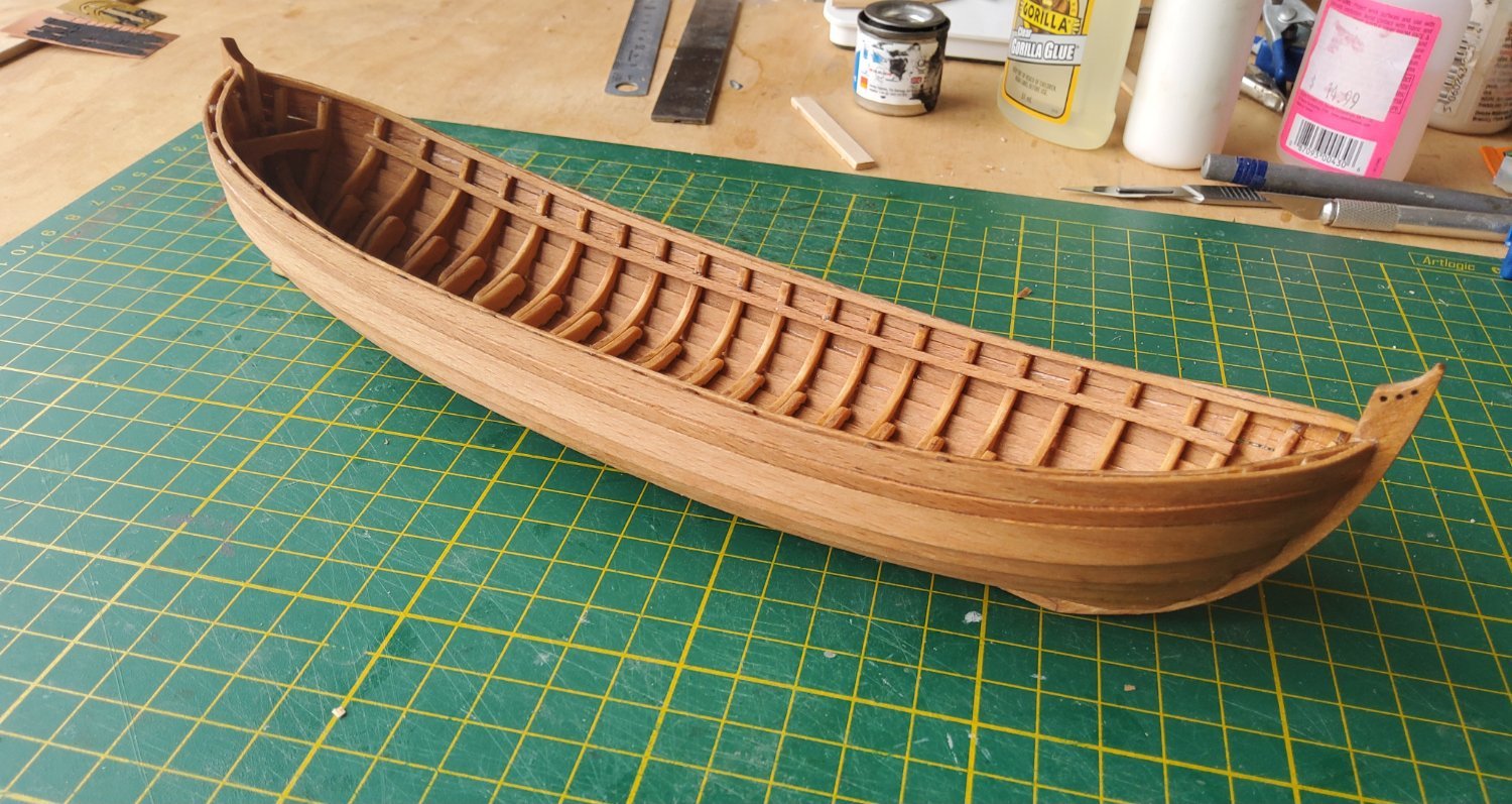
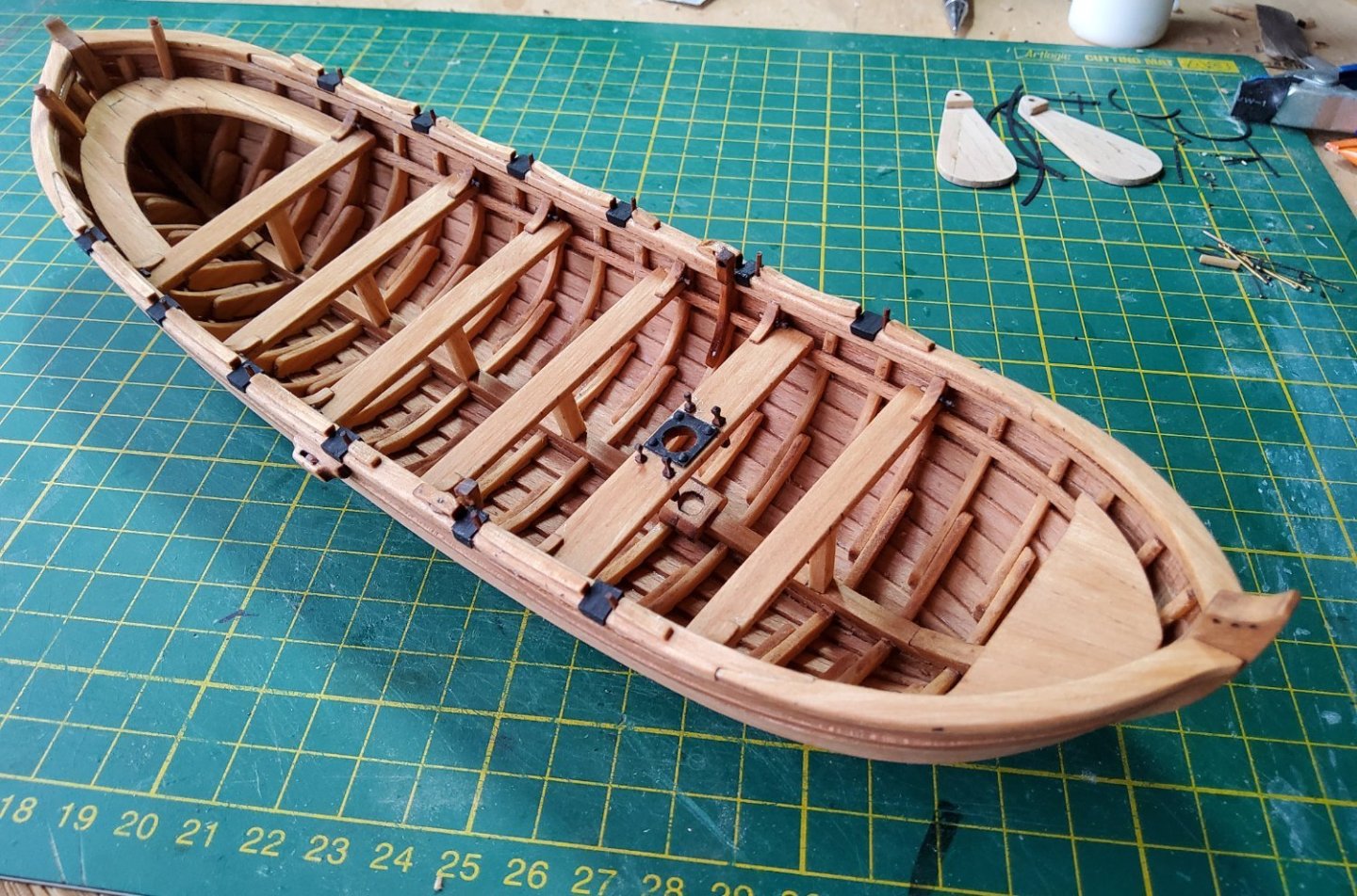
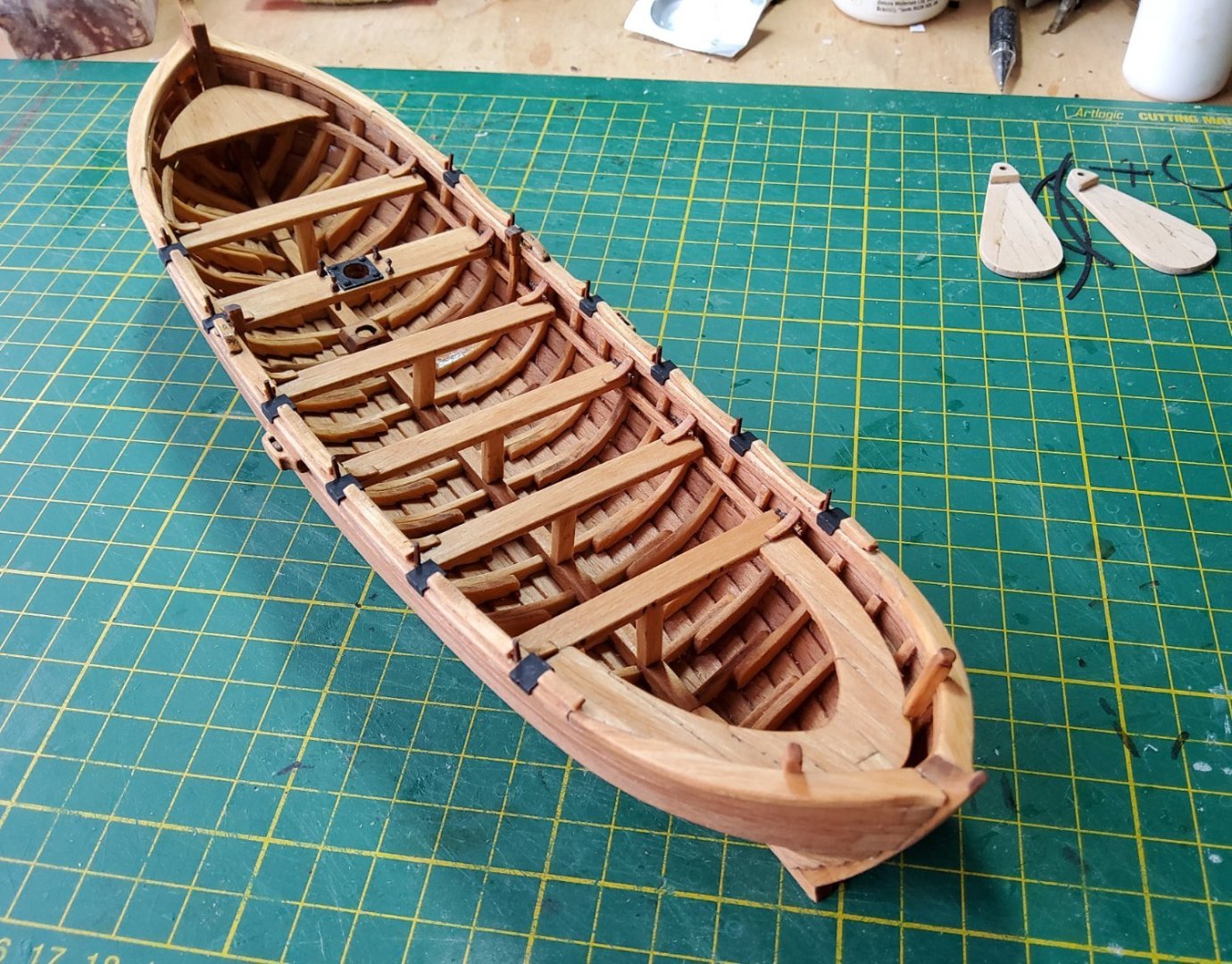
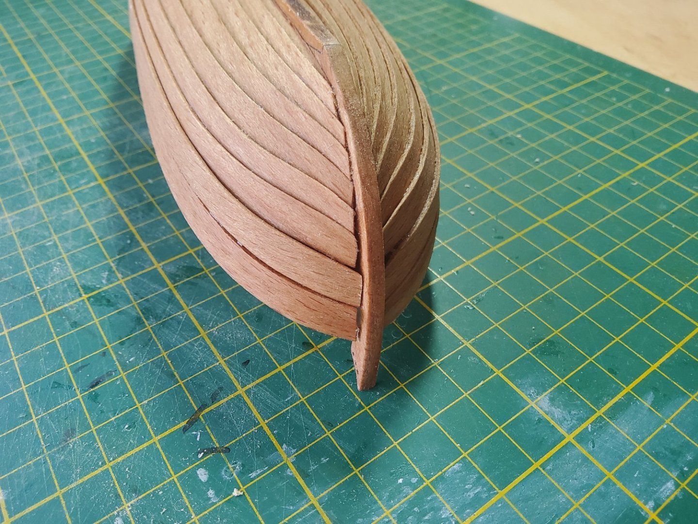
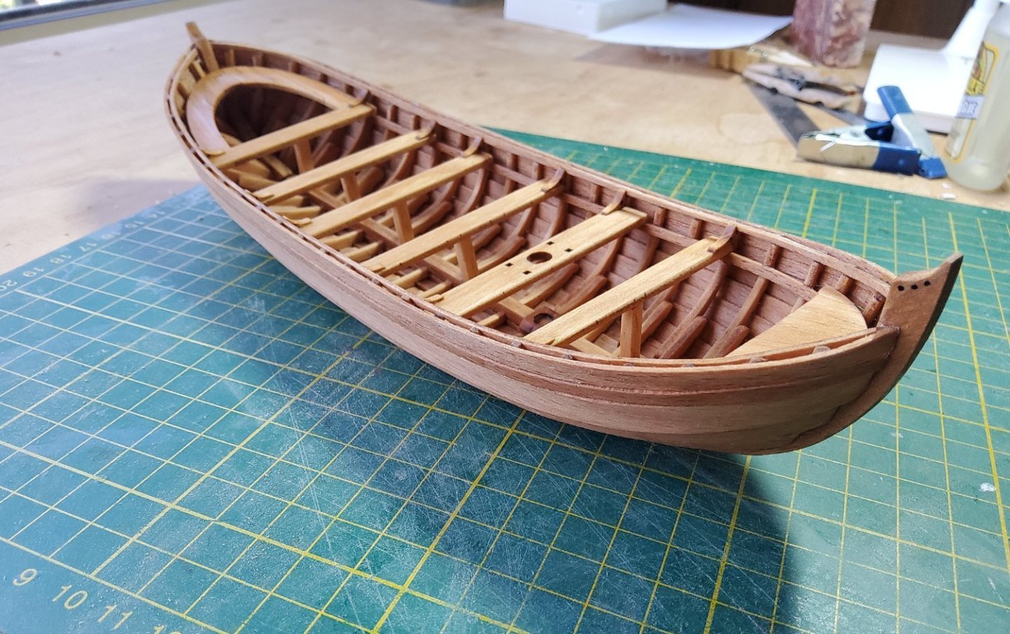
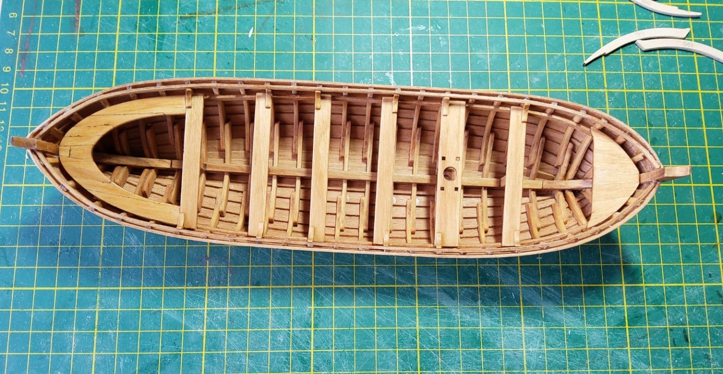
Other activities are taking a fair bit of my time, so this post will be primarily photos. The first two strakes in place. All the planks are spiled and laser-cut and only clean up of the char was needed. The boat is generally clinker-built, except for the two upper strakes which are carvel. There is one strake which abuts the nextmost upper strake in carvel fashion, but overlaps the strake below in clinker fashion. As there was no guidance as to how much overlap was required, I decided to work down from the top and add this hybrid strake last. There was a risk otherwise of the topmost strake being either too high or too low against the frames. This photo shows the topmost strake in place. The planking complete. Some minor trimming of the notches in the frames was occasionally necessary. Of more concern though, the upper planks were all slightly short, and short (a few mm) lengths of suitable scrap had to be inserted to close the gaps against the stern post. These aren't obvious from normal viewing distance. It's possible that I didn't fair the frames enough. The parts for the fore and aft decks; parts 47 an 48 have their numbers transposed though this was obvious enough. The thwarts and decks added to the hull. Cheers.


- 36 replies
-
- 10
-
-
- Shallop
- Pavel Nitikin
- (and 1 more)
-
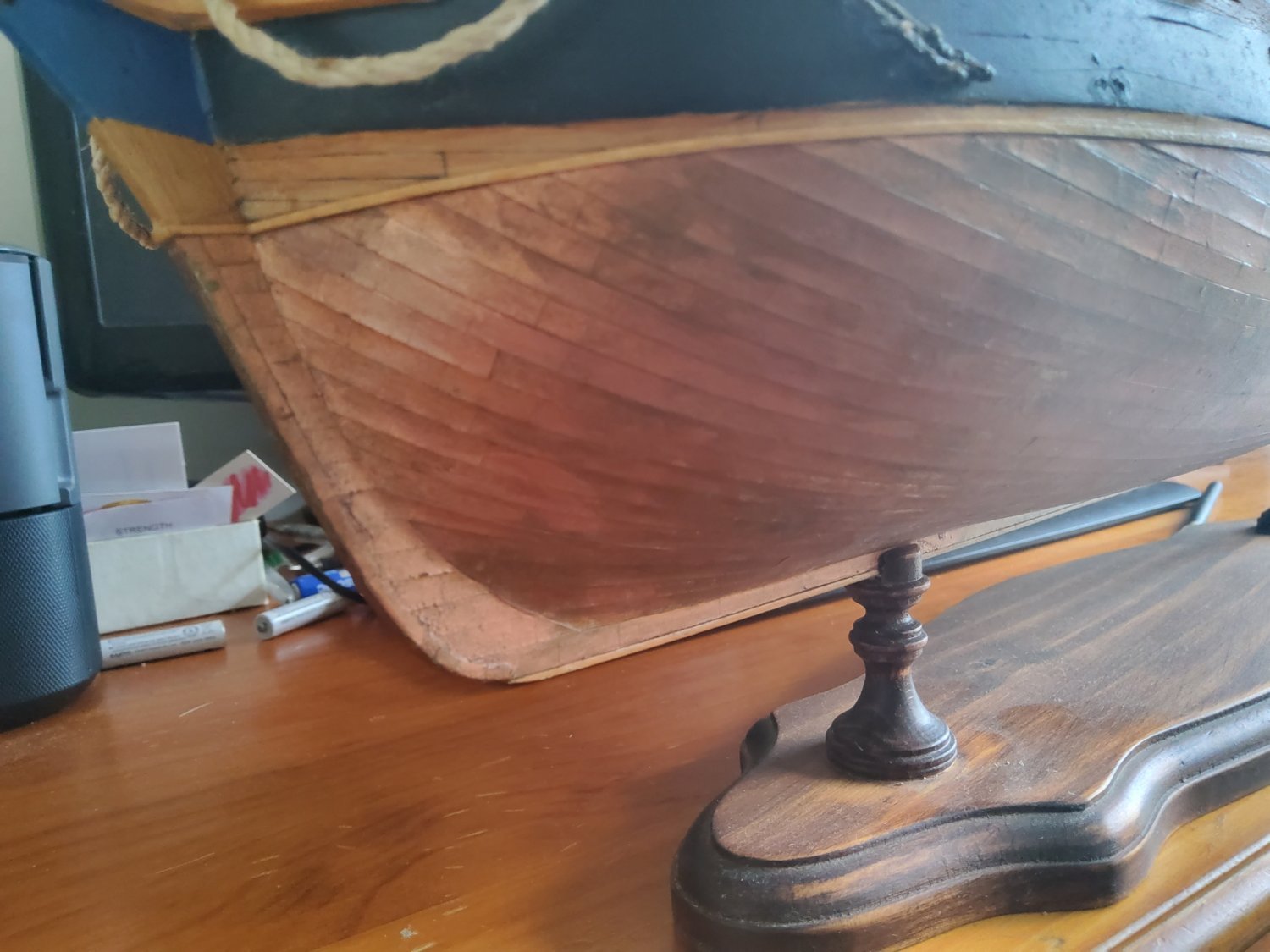
Hi Richard, This is the method I used to copper my Bellona (back in the days before the internet). All mentions are to pages in portrait orientation. I painted some sheets of photo-quality A4 paper with Humbrol copper paint, using a reasonably broad brush and brushing straight up and down, not trying to eliminate brush marks. I then marked the page along its long edges, with the marks being the length of a copper plate apart. A rotary cutter was run across the page from mark-to-mark, just lightly enough to score the paper but not cut through. The top and bottom were marked with the width of the plates, then the cutter was used to cut the page into long strips, with each strip resembling a line of plates. These were easily glued to the hull using ordinary PVA. Some final touch with a fine brush was done where white showed. Perhaps not a method agreeable to everybody, but it worked for me 🙂. The photo shows the bow of my Bellona. Cheers

- 49 replies
-
- 2
-
-
- Pegasus
- Victory Models
- (and 1 more)
-
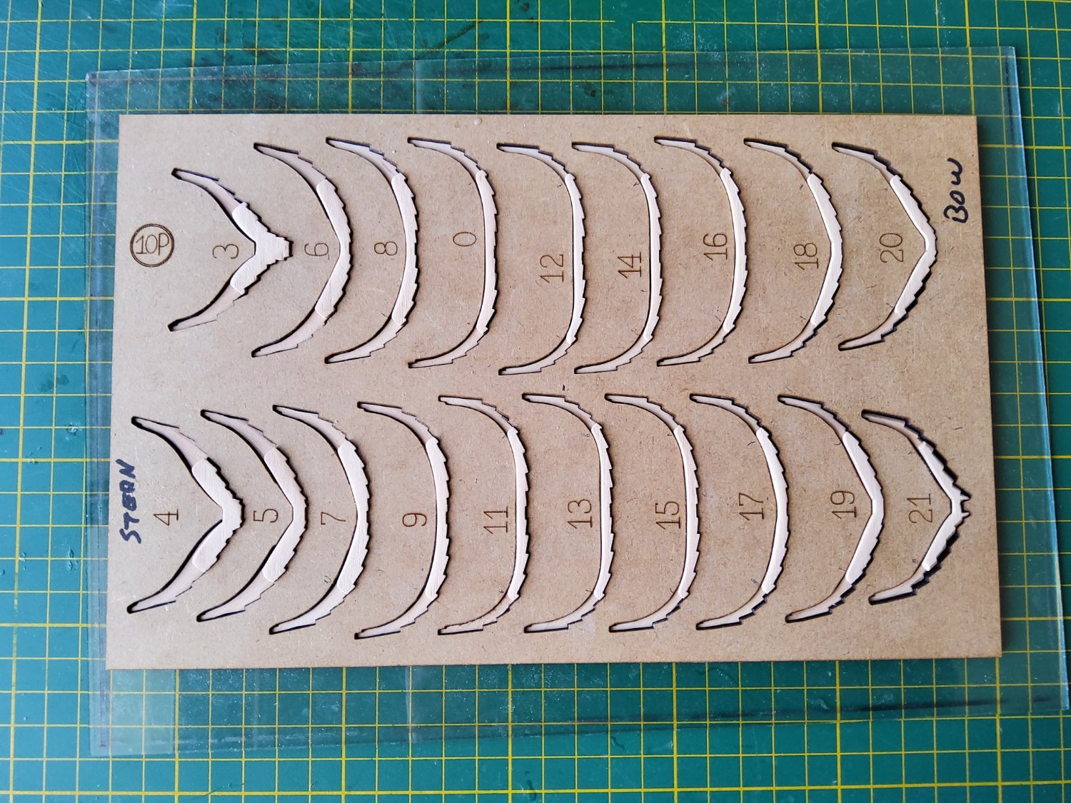
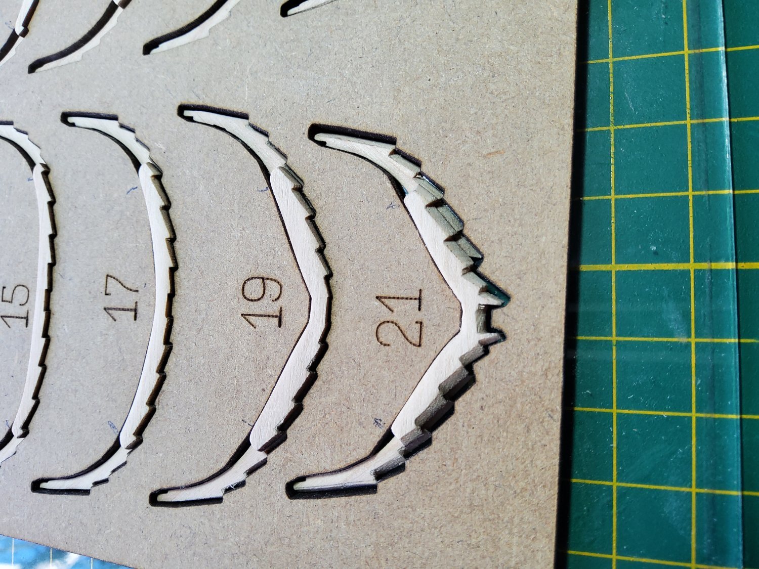
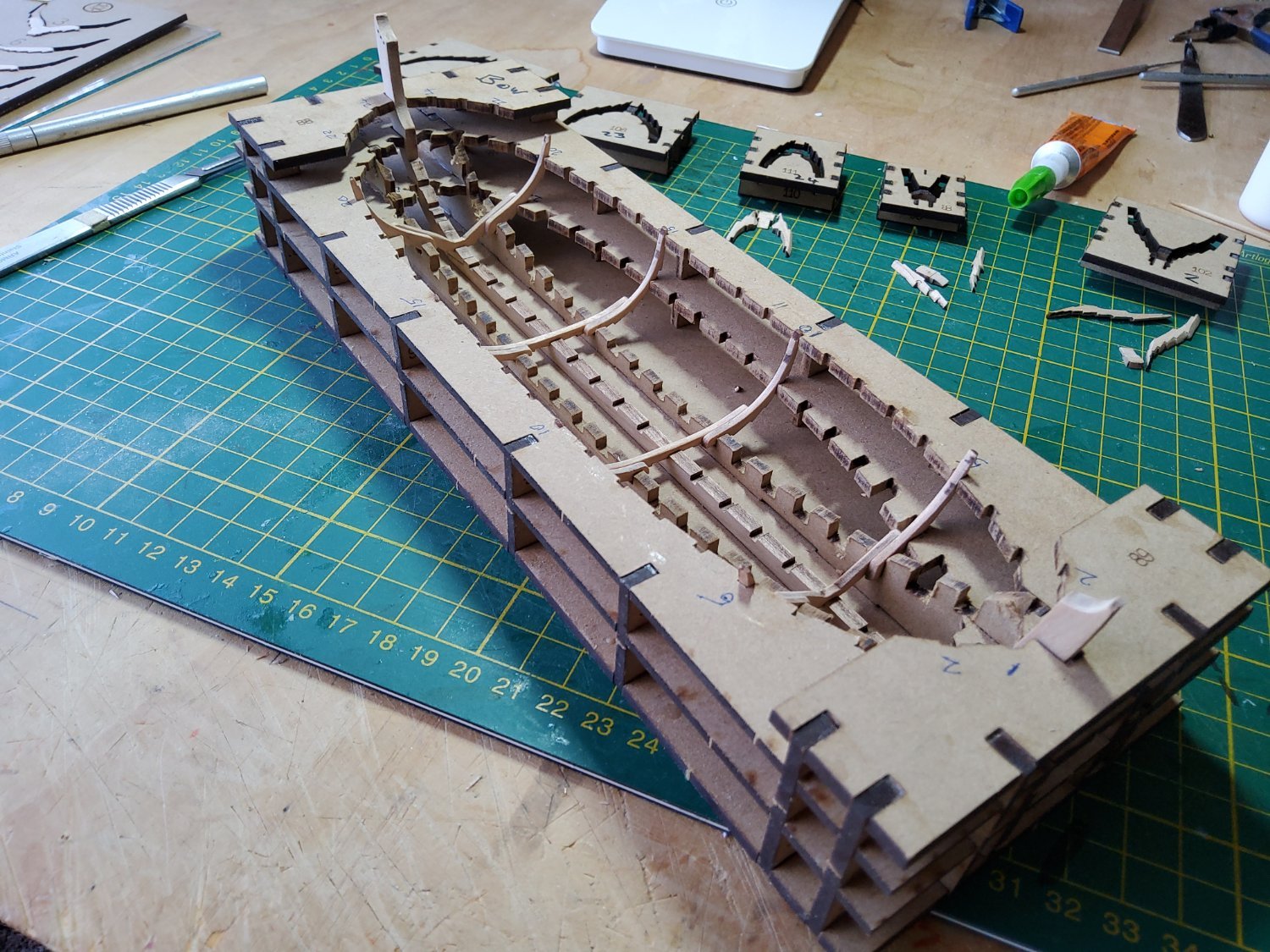
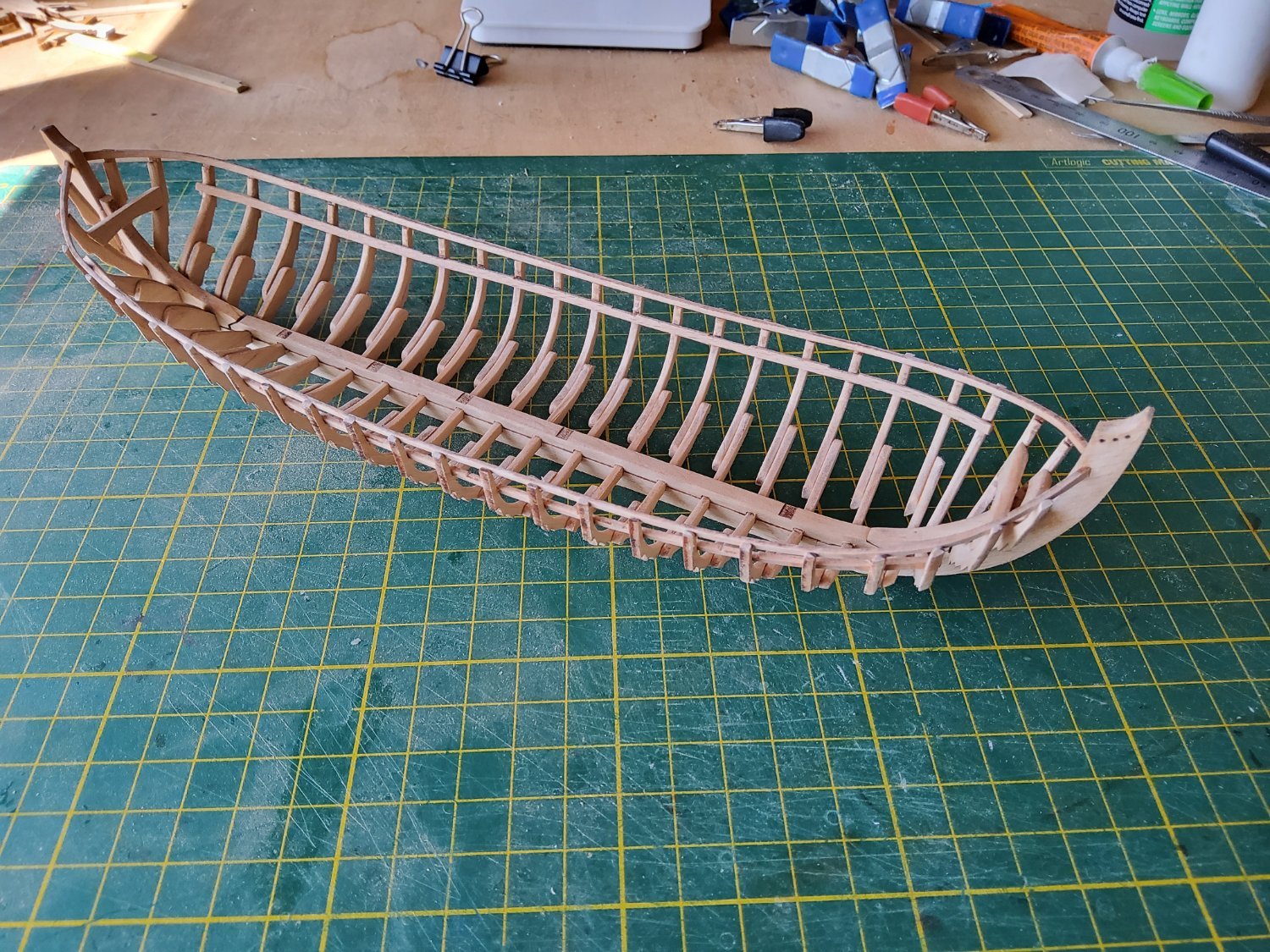
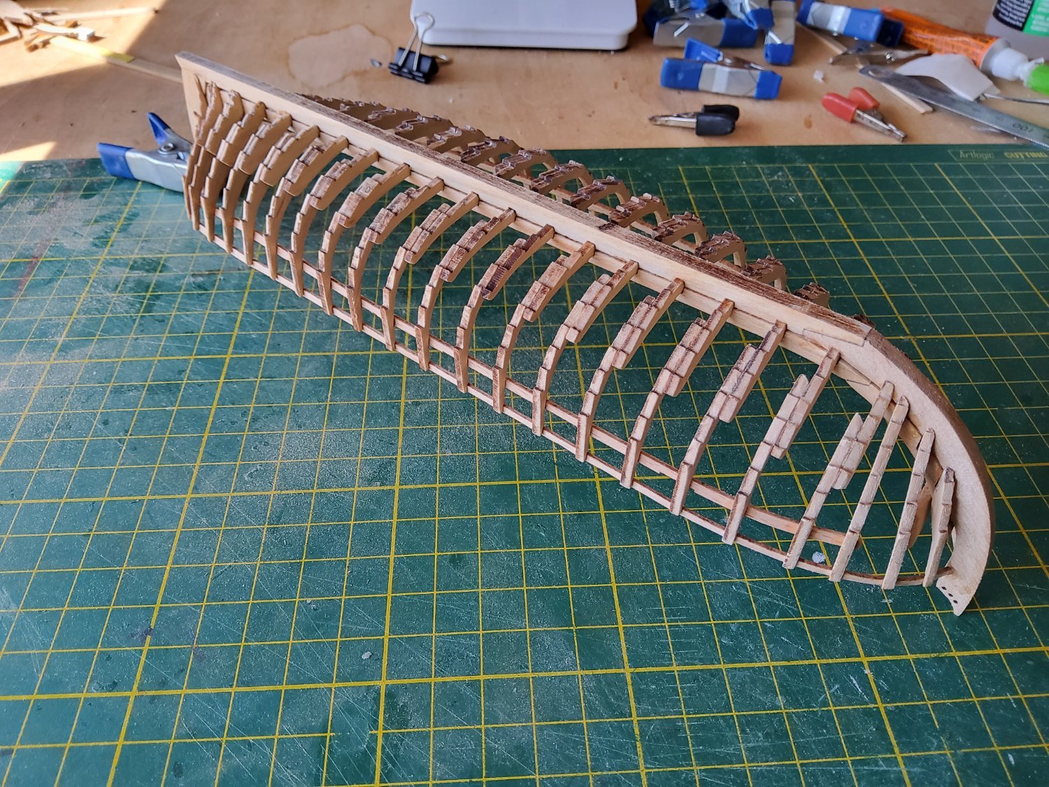
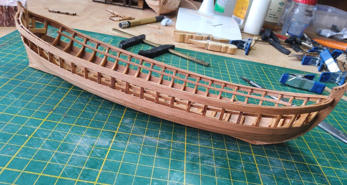
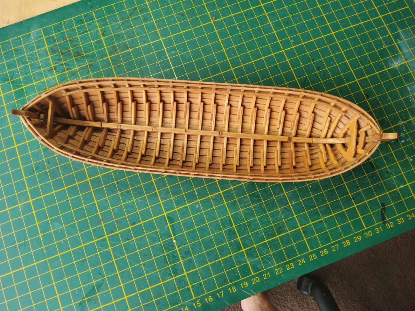
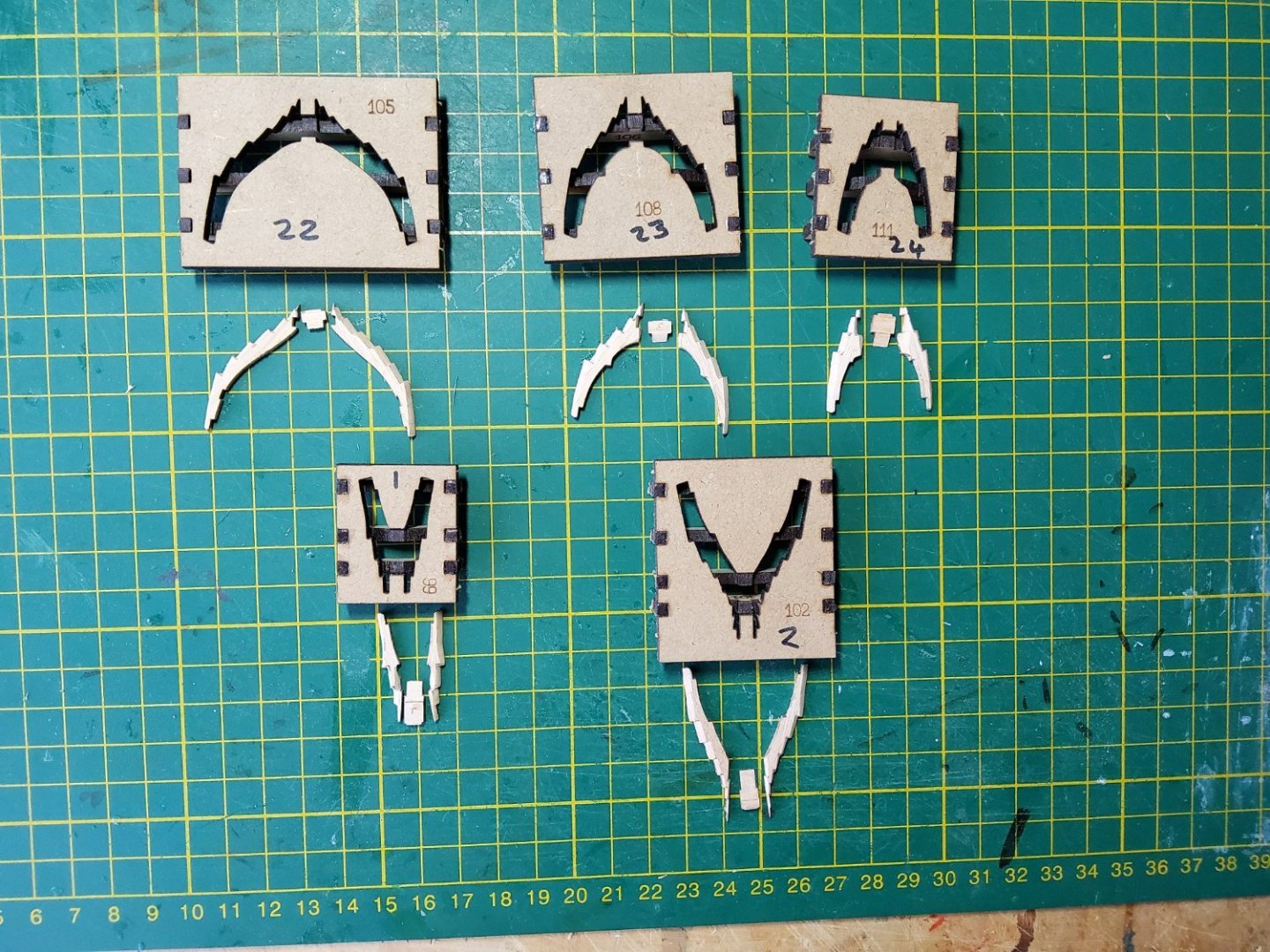
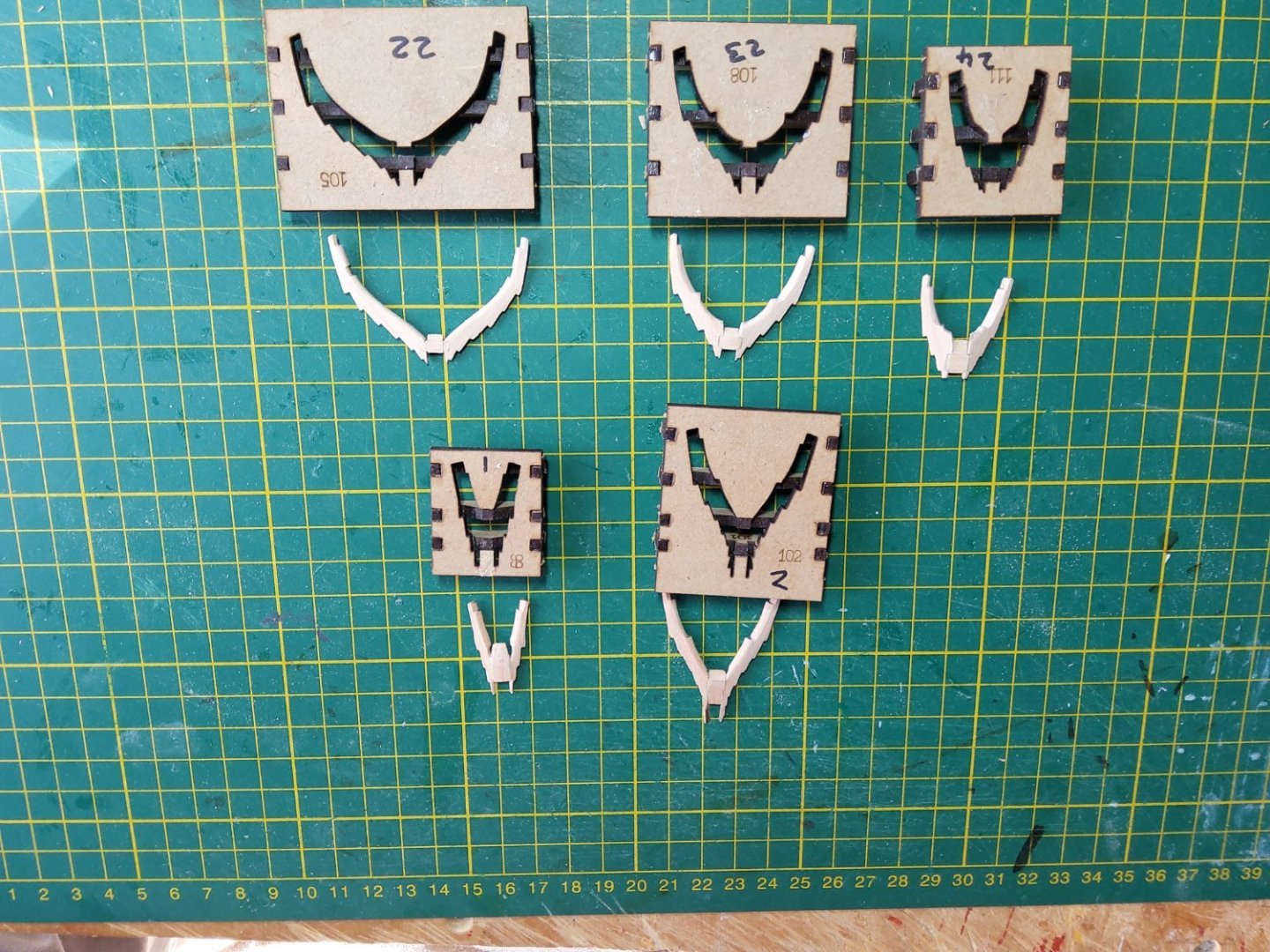
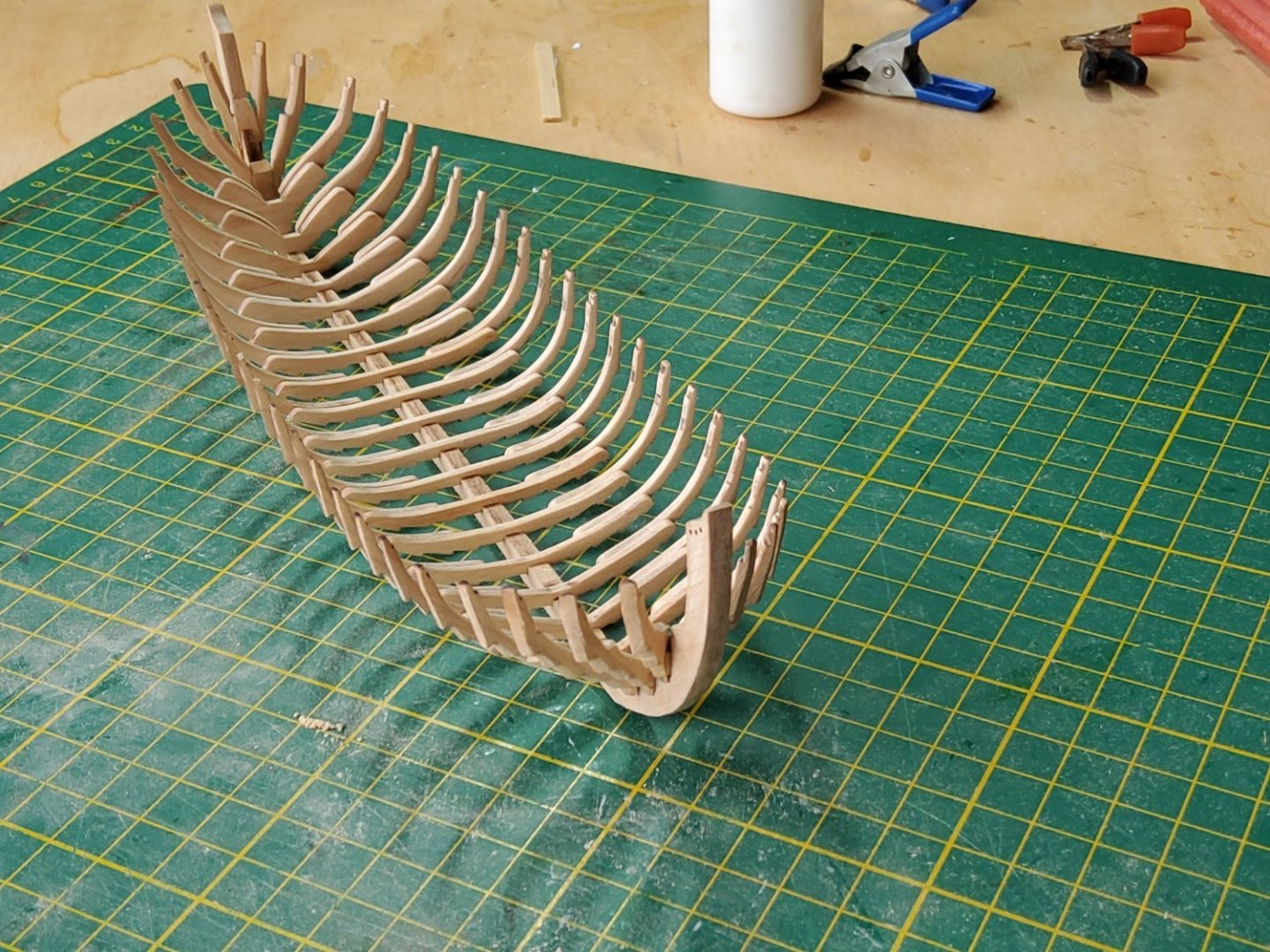
After seeing JamesH's review of this kit (here) I decided it would be a good one for me to build. Small, as I have limited space, only one mast and no rat lines 😁. I then found the videos by Olha Batchvarov (here), and she made it look so easy. There are a few members on MSW who have mentioned the shallop, but as far as I am aware, there is no actual build log. There are three main jigs to be used at various times, all of which were easy enough to assemble, though some easing of slots was required. The first jig is used to build the 20 main frames, plus there are five cant frames (each with its own jig), three at the bow and two at the stern. The latter consist of two futtocks (I assume that’s what they're called) joined by a cross piece (chock), while the former have two futtocks and a floor that overlaps them. All pieces have laser etch marks to show how much fairing is required to allow a fair run of the planks. The boat is clinker-built, so all frames are notched for the planks. The illustrations on how to assemble the main frames were somewhat confusing (there are no written instructions), but after some thinking and doing a couple of dry fits, it became obvious that frames 3-12 (towards the stern) had to have the futtocks and the floor placed with the etch marks downwards, while the other frames (towards the bow) needed to be placed with etch marks upwards. The floors were always placed on top of the futtocks. The frames in the jig, and a close-up of frame 21, showing the fairing. I faired the futtocks and the floors before assembly. The cant frames were difficult as some fairly precise sanding of angles was required to get the three pieces of each frame assembled correctly in its little jig. Again, thinking before glueing was definitely needed. The parts for the cant frames and their jigs…. ….and assembled. The keel, stem and sternpost were glued together, let dry, and placed in jig 2. As there was a small amount of sideplay, four completed frames were carefully glued in position, making sure that they and the keel were correctly centred on each other and in the jig. By doing this, the keel was kept firmly in place. All other frames were then glued to the keel. Two stringers were soaked, bent, then glued to the frames. The keelson and some other pieces were added. Next up, planking. Cheers


- 36 replies
-
- 7
-
-
- Shallop
- Pavel Nitikin
- (and 1 more)
-
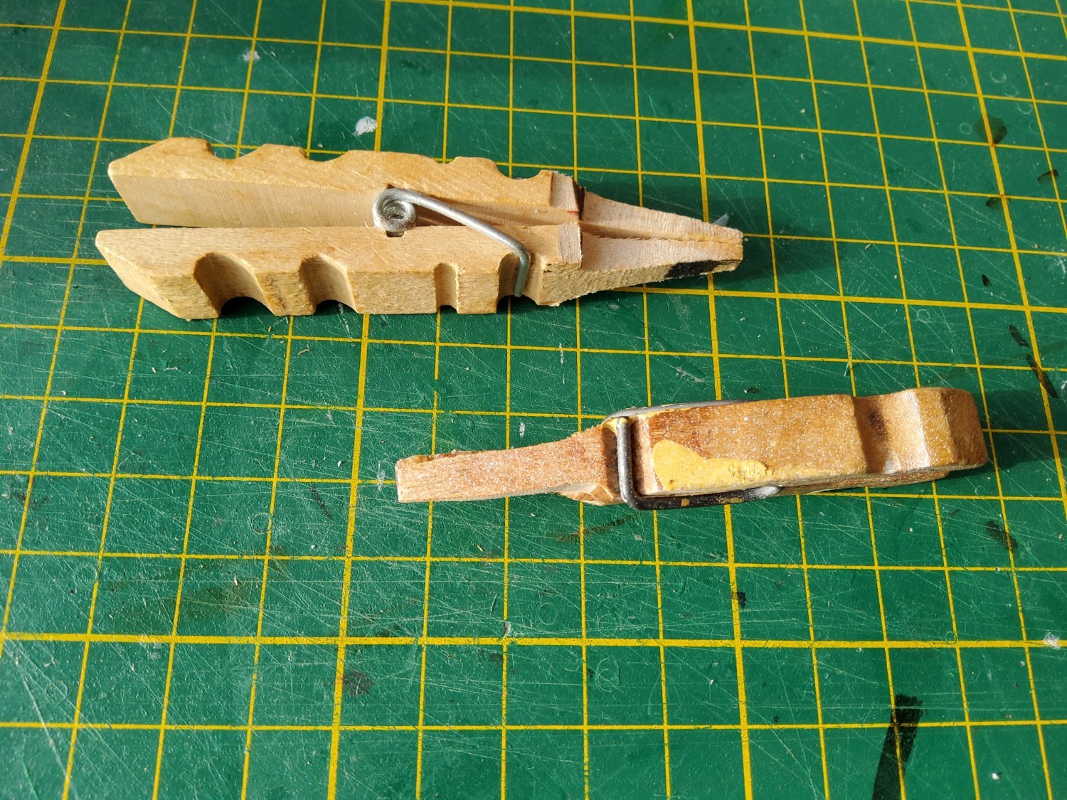
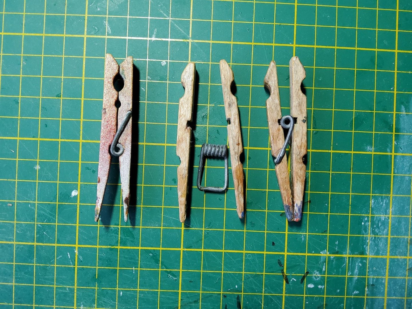
Thanks Steven. Another trick is to disassemble the pegs and reassemble them so that you get a much larger flat, and tapered, surface that will help with the clamping. Cheers PS Those pegs have seen a lot of models. 🙂
- 24 replies
-
- 6
-
-
- Ships boat
- Ships of Pavel Nikitin
- (and 1 more)
-
You can also use normal pegs and cut them down to suit. These were reversed before doing so.

- 24 replies
-
- 3
-
-
- Ships boat
- Ships of Pavel Nikitin
- (and 1 more)
-
Are you sure about that? Seems odd to me. Is your keel assembly fully seated in the jig? You may need to ease the slots at each end of the jig to allow this. Maybe try dry fitting a frame or two and see whether they are correctly fitted on the keel and in the jig. Should be a neat little model. Edit. You may need to ease the slots in the jig to allow the frames to fit snugly without having to push them hard. Cheers
- 24 replies
-
- 2
-
-
- Ships boat
- Ships of Pavel Nikitin
- (and 1 more)
-
Impressive!
-
Thanks Steven. I never saw the TV show, so can't comment on Sigrid's acting ability. Didn't see Sea Change either. 😁
- 18 replies
-
- 1
-
-
- Pevensey
- World of Paperships
- (and 2 more)
-
Thanks everybody for the likes and comments. I remain in awe of your skill with wood, B.E., and yours with card Chris. On to the next build, a wooden boat this time. The build log will start soon. Cheers
- 18 replies
-
- 1
-
-
- Pevensey
- World of Paperships
- (and 2 more)