Richard44
-
Posts
429 -
Joined
-
Last visited
Content Type
Profiles
Forums
Gallery
Events
Everything posted by Richard44
-
 You're not wrong B.E.. The actual assembly of the guns was spread over several weeks, so not too bad. But getting the guns fixed on the deck was an exercise in patience. Getting the ringbolts/breech ropes in place wasn't too awkward, but those frapped train tackles..... Anyway, the next task is the chain pumps. Then the rest of the deck furniture. Cheers
 -
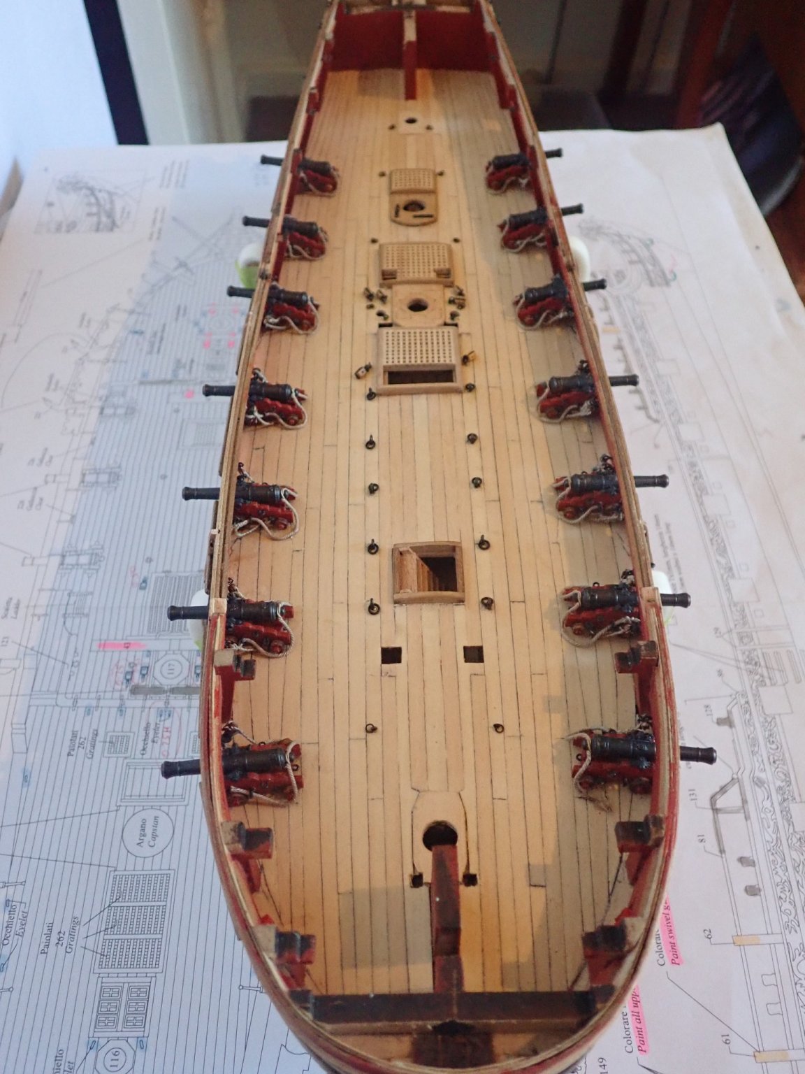
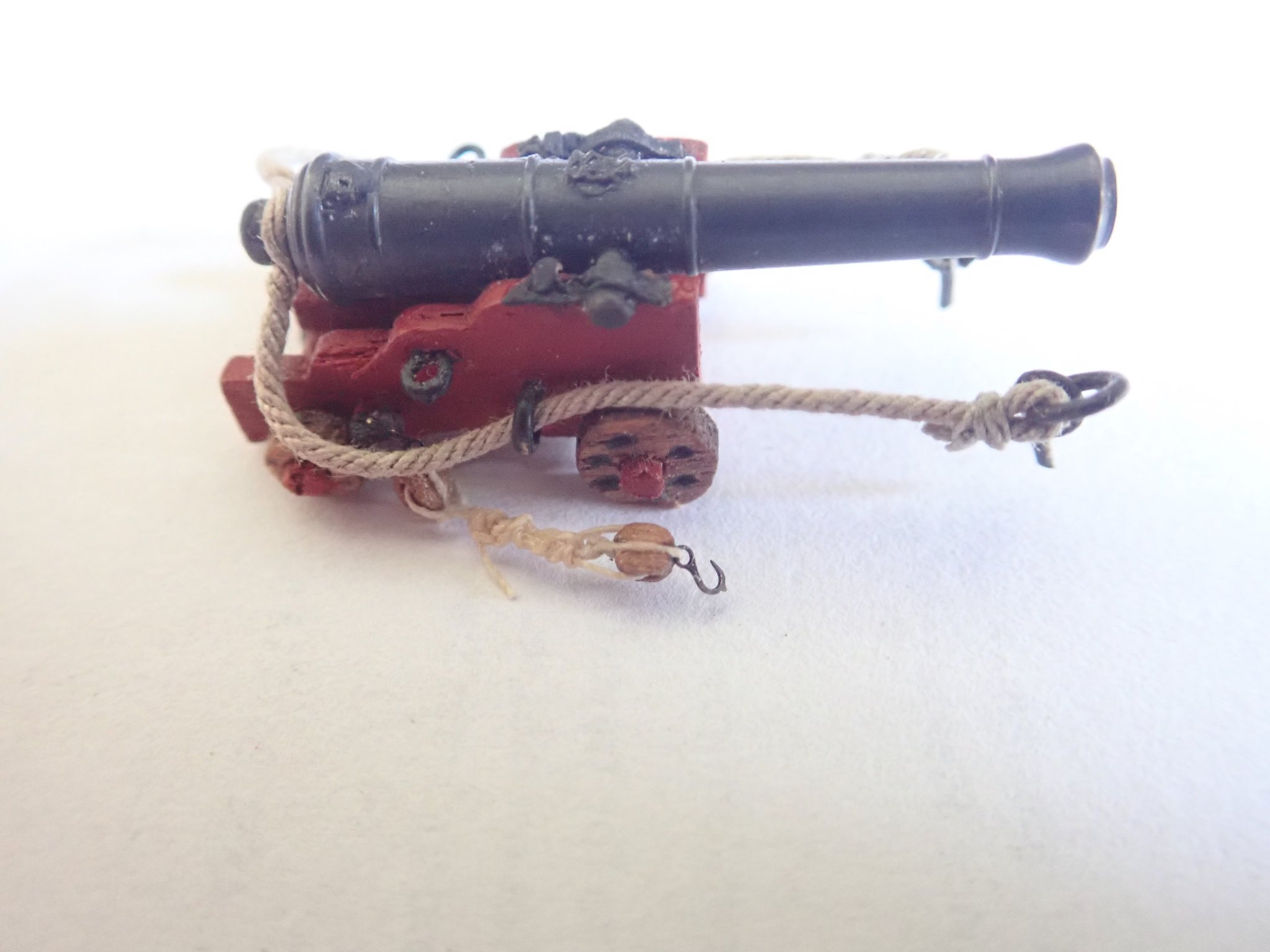
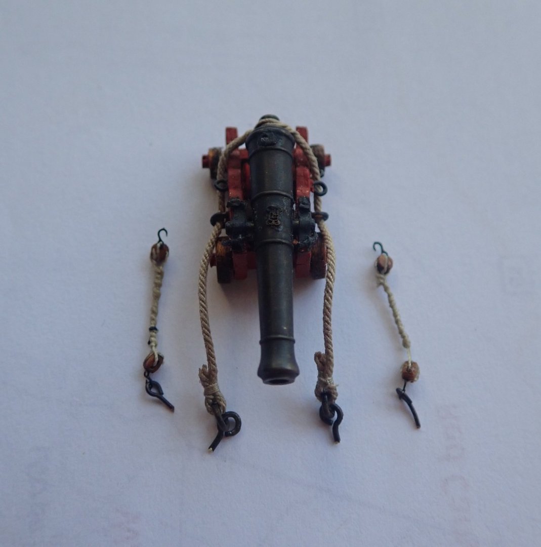
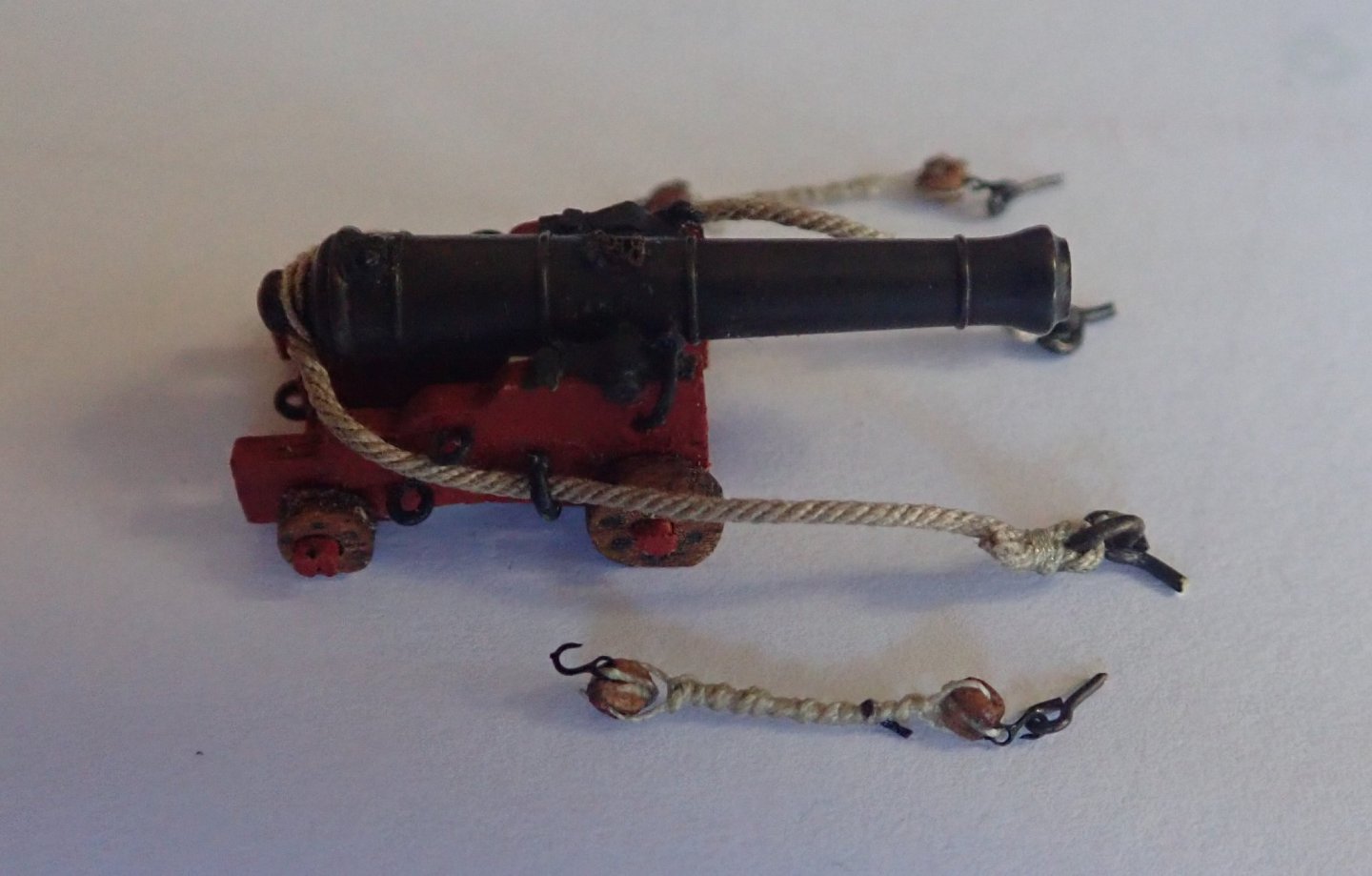
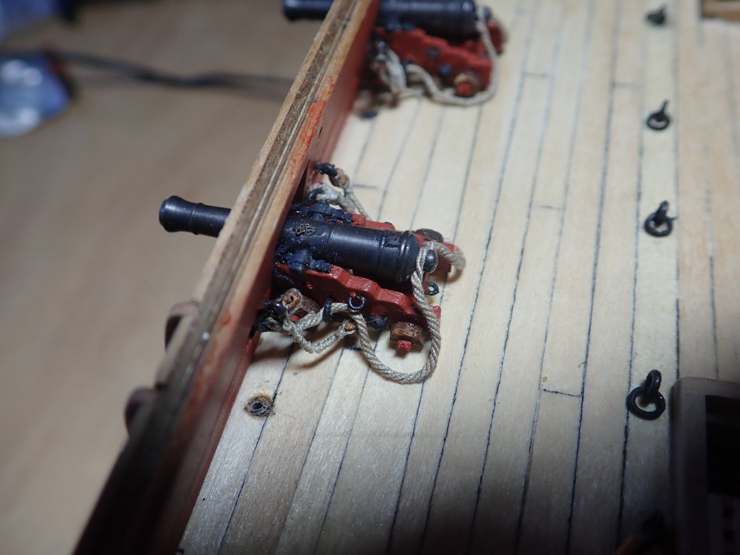
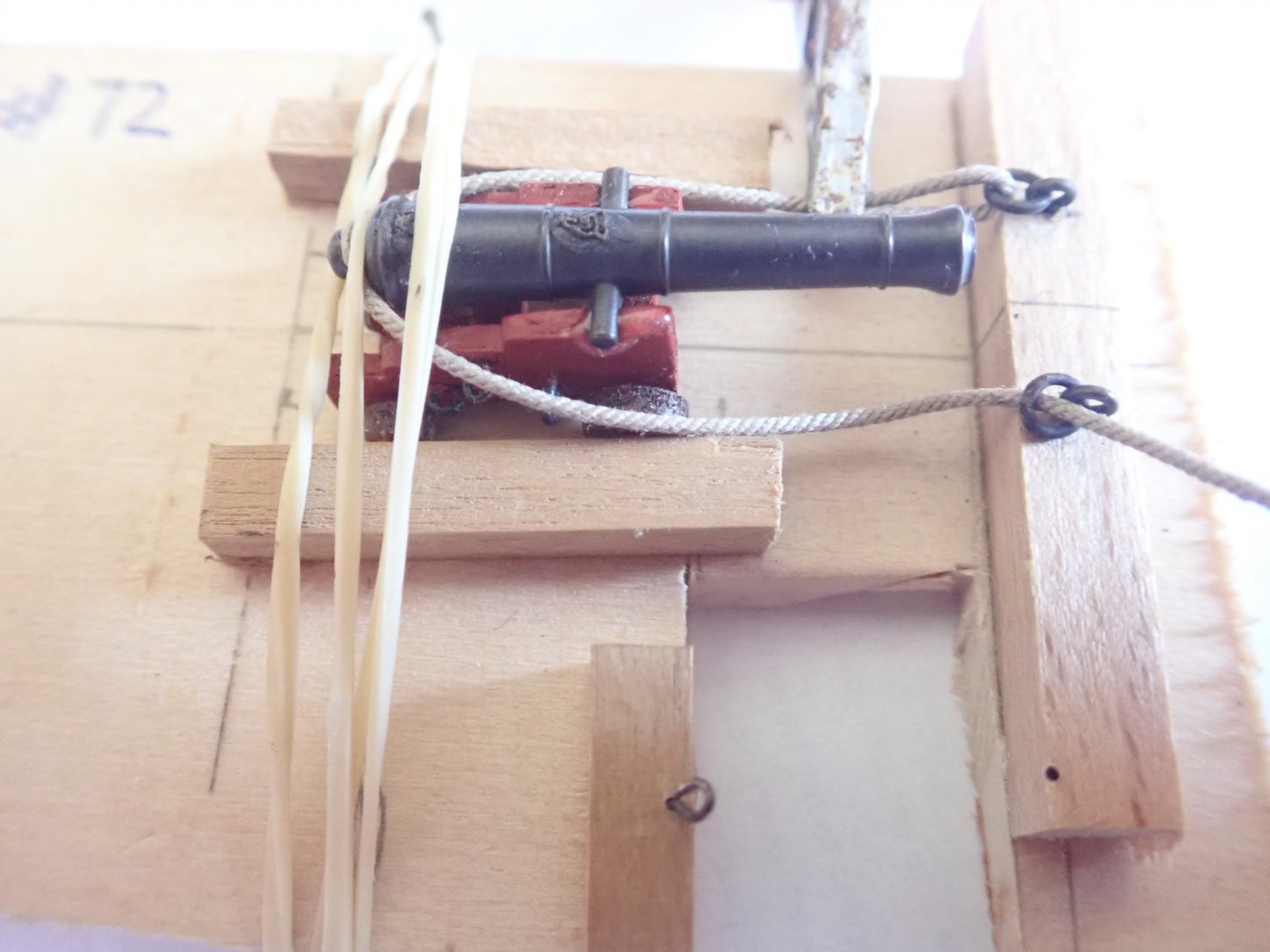
Thanks for the likes. The guns have been completed and installed on the deck. I have however ignored the instructions that suggest mounting only the carriages of the guns that are under the fore and quarter decks, and later gluing the barrels onto the carriages by pushing them through the gunports. I know the guns are now somewhat vulnerable to being knocked, but I’ll take that chance. As described in a previous post, I’ve added the monogram and touchhole to the barrels, and have done both the breech rope and the train tackles, the latter being frapped. The breech ropes needed a little PVA to make them lie naturally. If I were to do this again, there is one thing I would alter - use eye-bolts instead of ring-bolts to attach the breech ropes. The latter is correct but space on the model was very cramped with the ring there - and it’s not visible anyway. A gun ready to be installed on the deck. Installed. The completed deck. Cheers

- 104 replies
-
- 5
-

-
- pegasus
- victory models
- (and 2 more)
-
Yes, excellent work Eugenio.
-
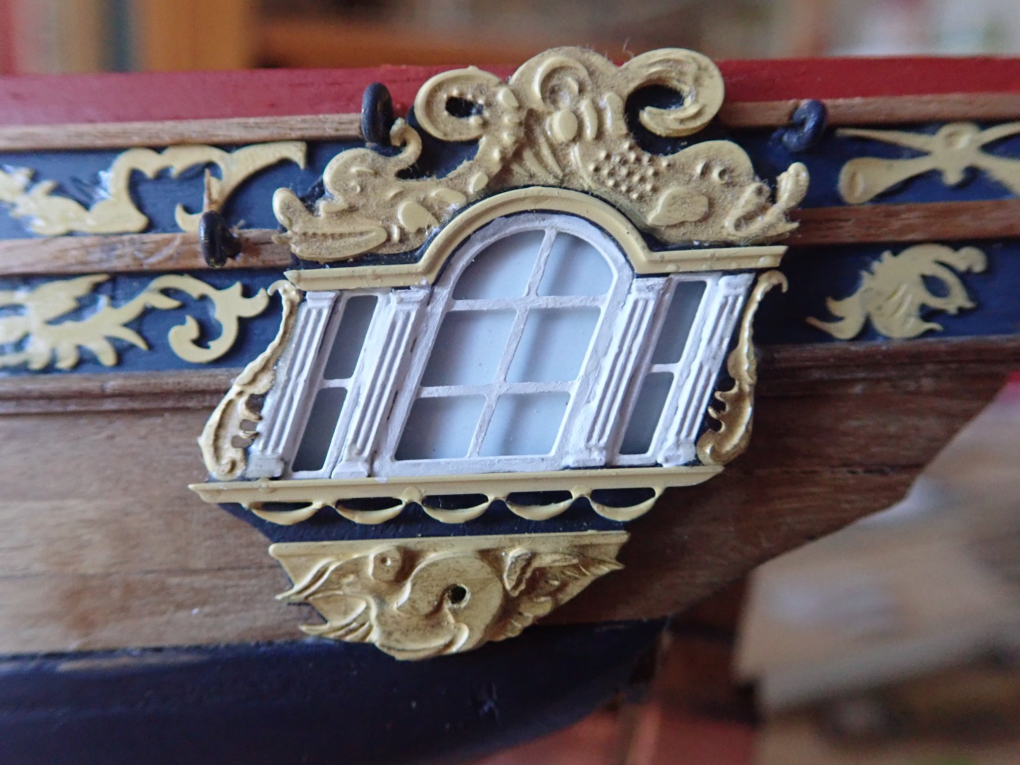
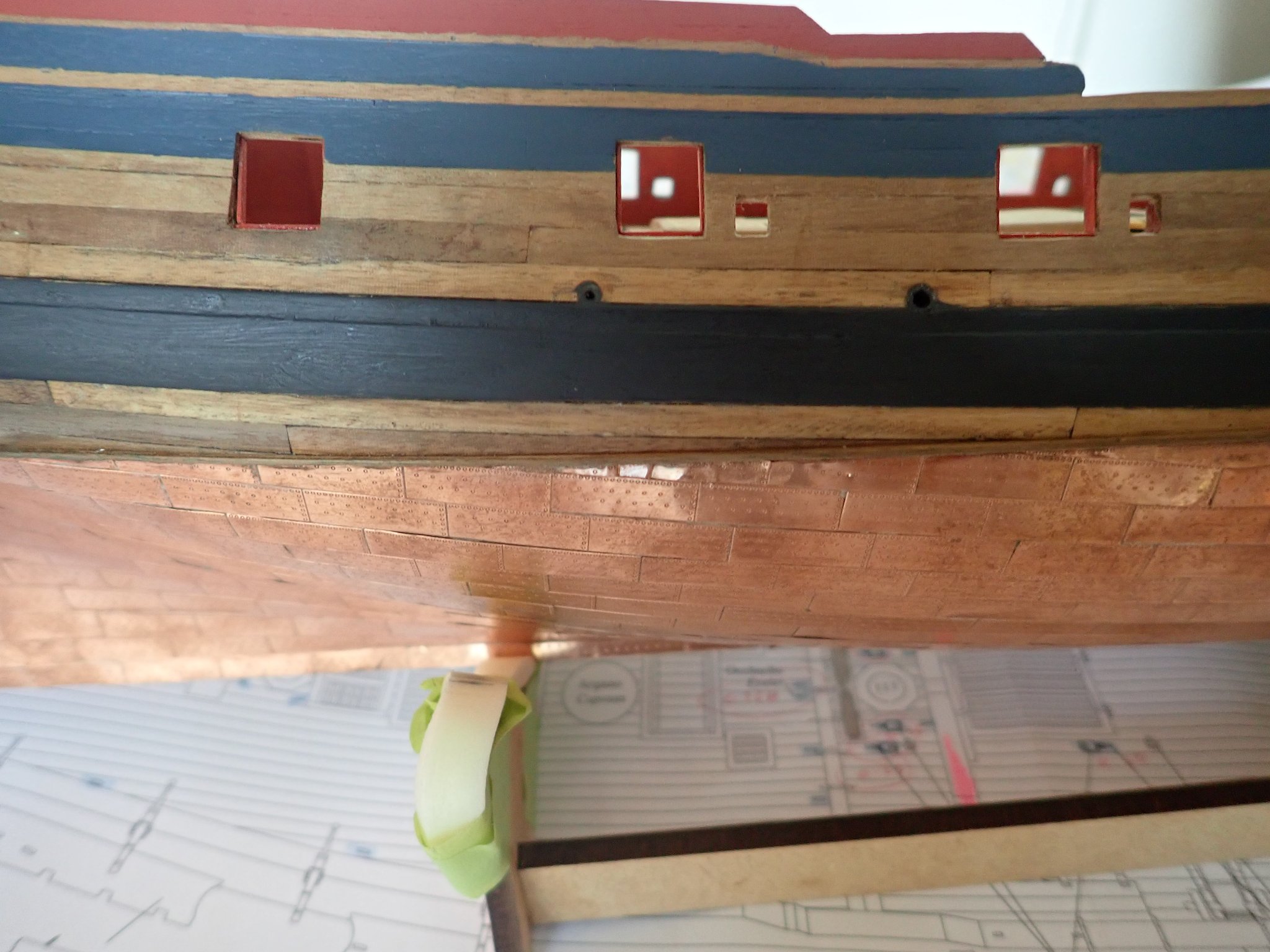
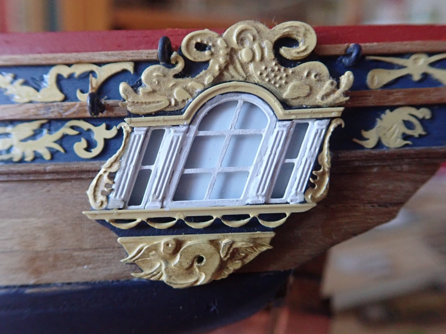
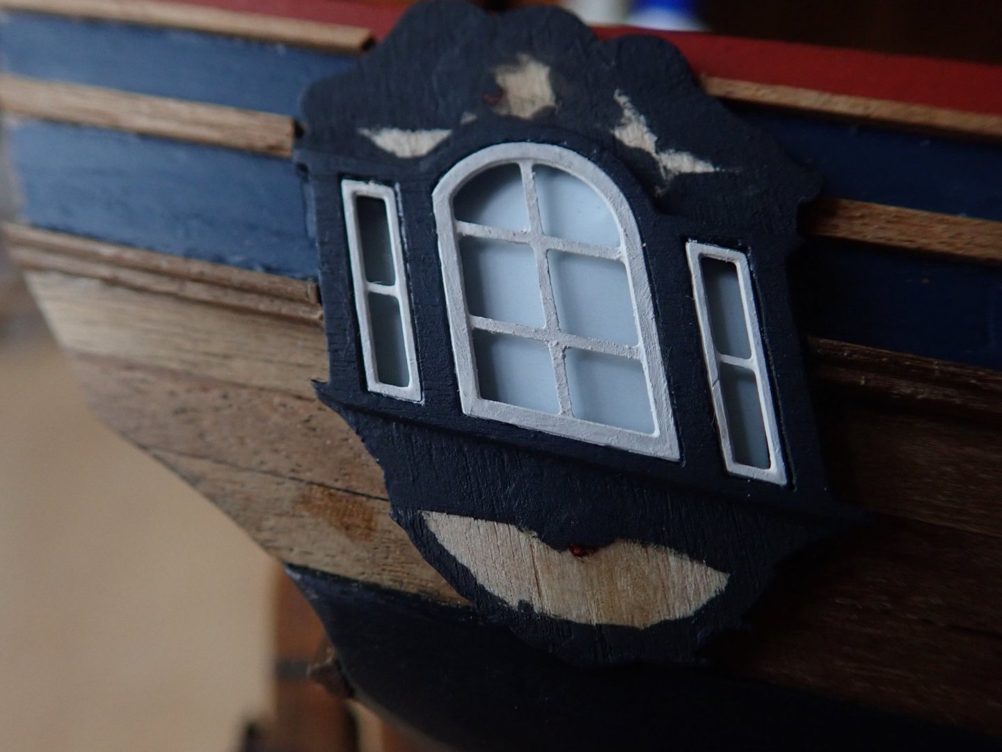
Thanks for the likes. Hi Spyglass, Those little “swags” as you called them are noted as being painted blue on the plan. However, they are basically unseen against the black background, so I’ve repainted them ochre, to match the other decorations. And yes, they are very fragile - I actually lost one due to a slightly too brisk stroke with the paintbrush. The chances of finding it were zero. The retouched quarterlight. Cheers
- 104 replies
-
- 4
-
-
- pegasus
- victory models
- (and 2 more)
-
Hi Tom, Thanks for the comment. The blue on the hull is Humbrol #96, RAF matt blue, lightened slightly with some white. The blue behind the windows was just selected on the computer. Cheers
-
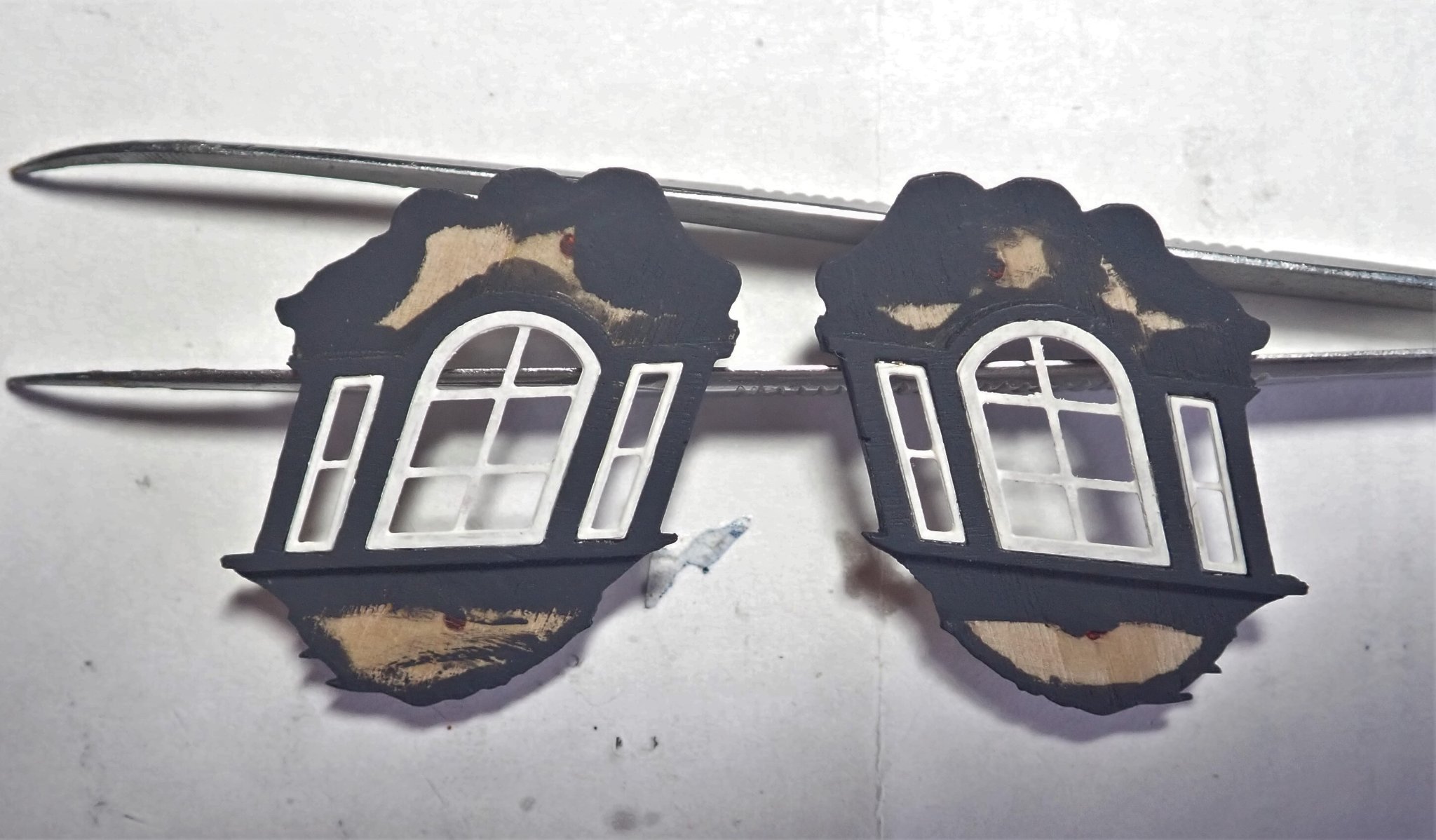
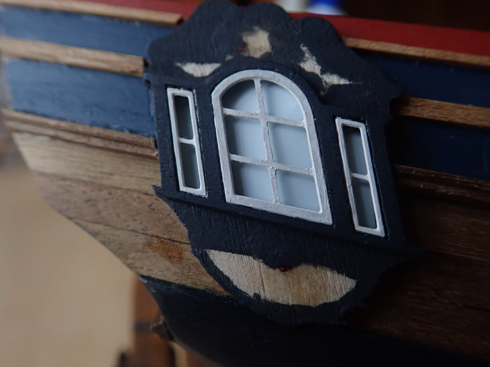
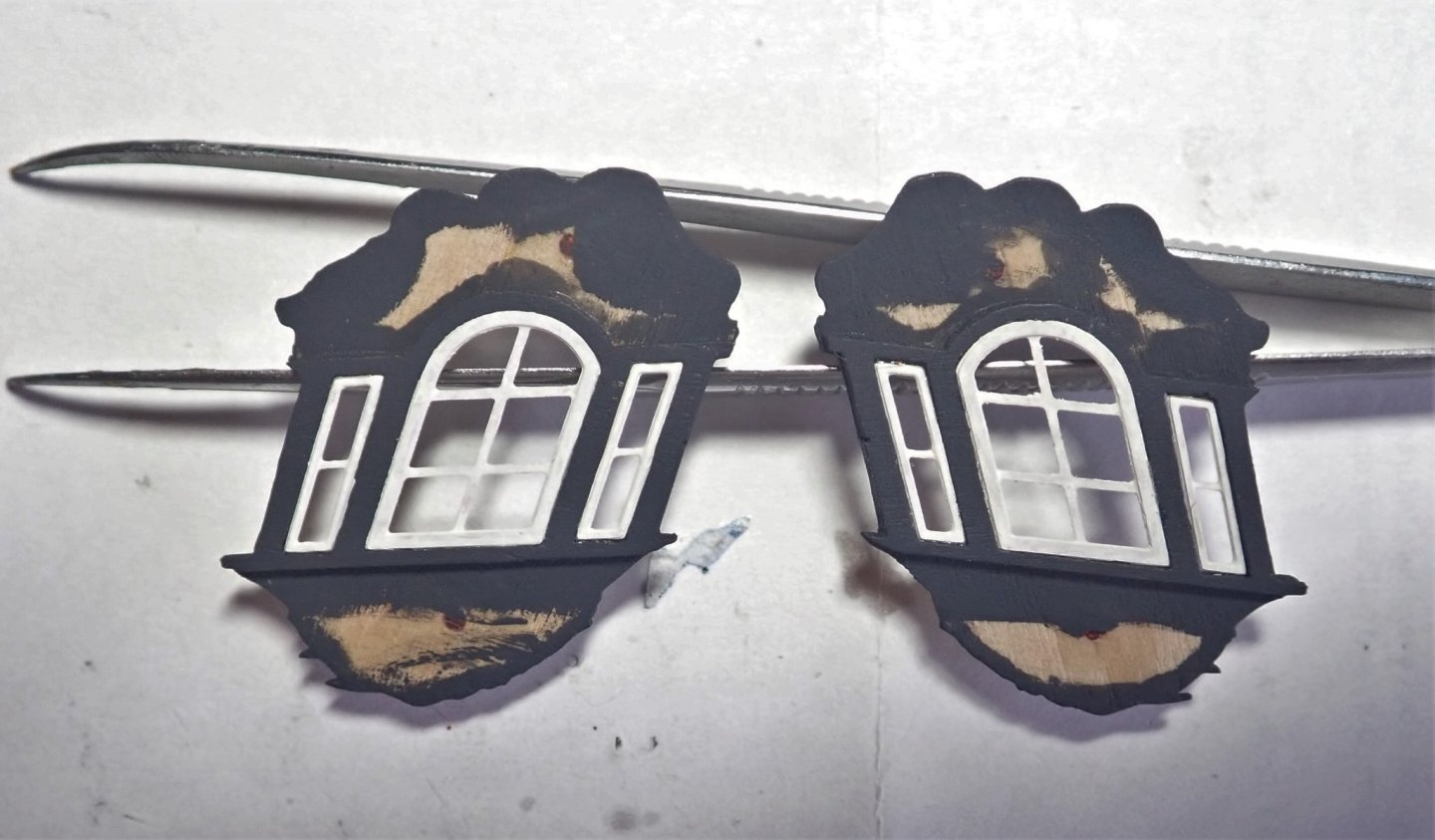
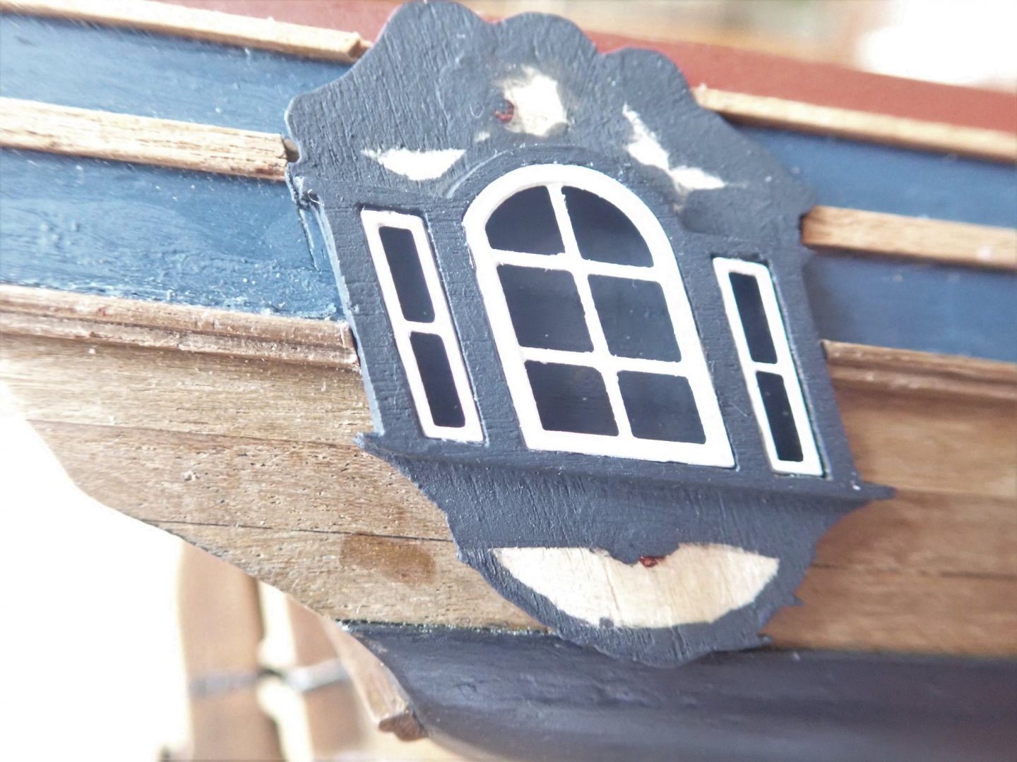
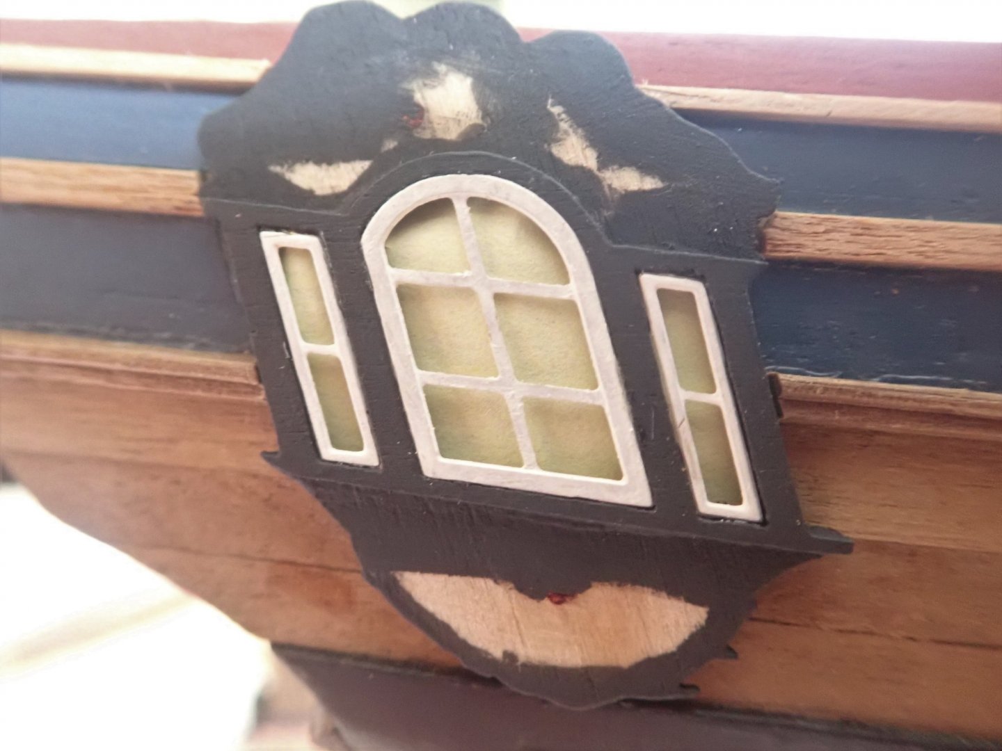
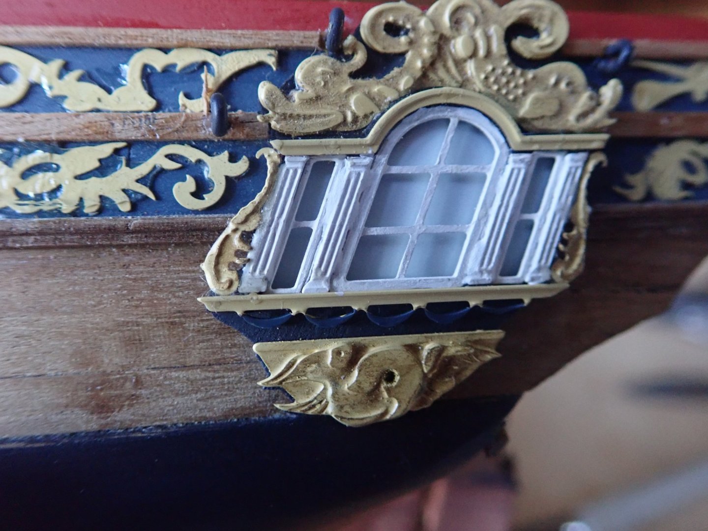
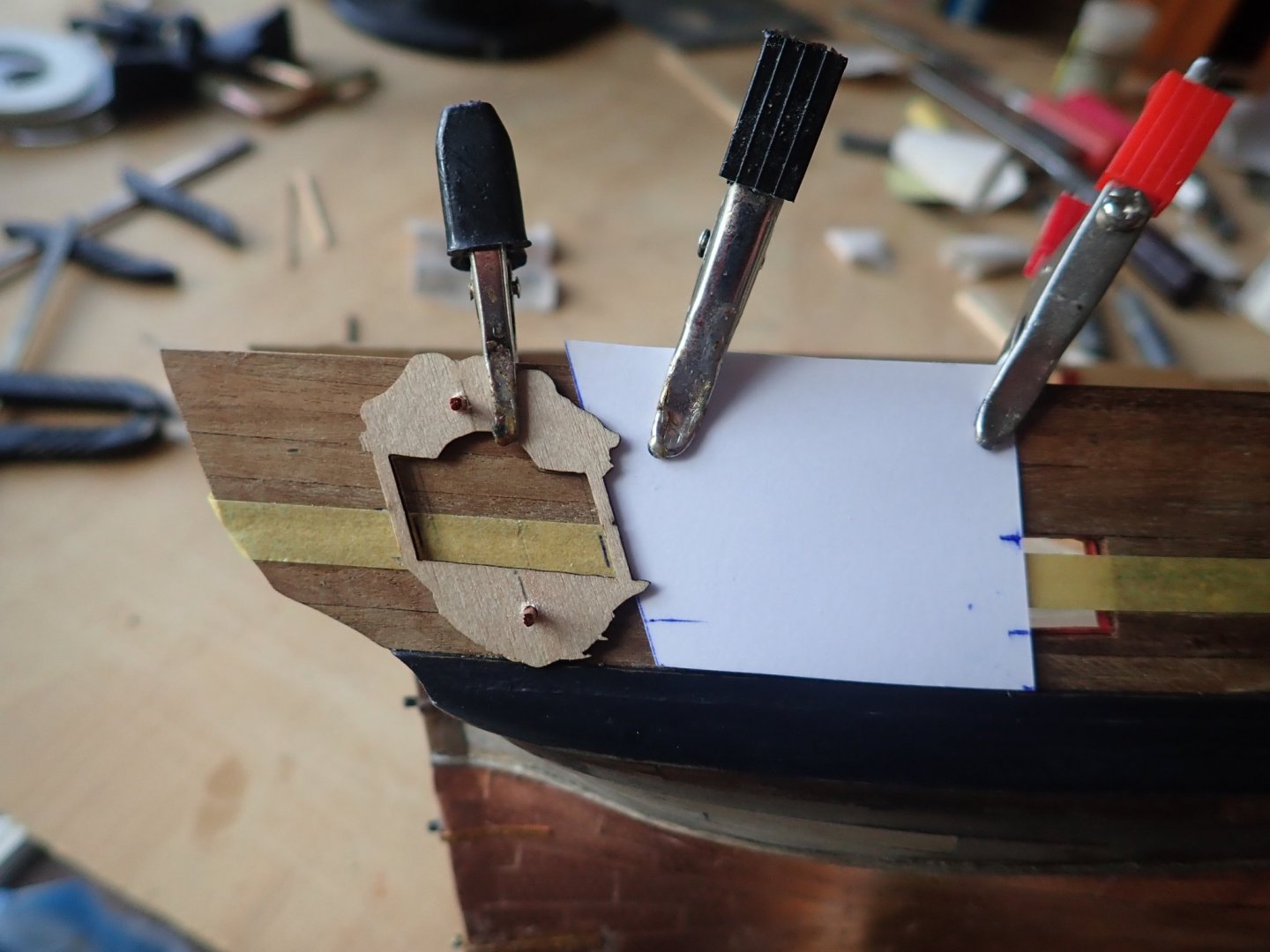
Thanks for the likes. The quarterlights. These were assembled as per the instructions. I decided to glaze the windows, but was not especially happy with what would have been a black background behind them. So I decided to put a coloured backing behind the glazing. I tried pale blue and pale yellow, and settled on the pale blue. I then had a happy thought. Instead of a piece of coloured paper, then the acetate glazing (supplied in the kit), I would print the colour onto gloss photo paper and just use this, the gloss finish giving the appearance of glazing. The painted, brass, window frames glued in place on the wooden patterns. The quarterlights with black, pale yellow and pale blue backgrounds. The latter two were trialled with pieces of paper, there is no glazing in any of the three. The completed quarterlight in place. Cheers for now.
- 104 replies
-
- 4
-
-
- pegasus
- victory models
- (and 2 more)
-
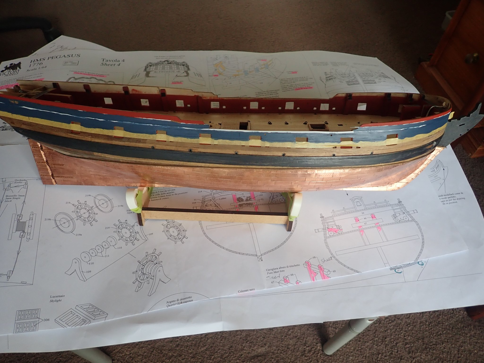
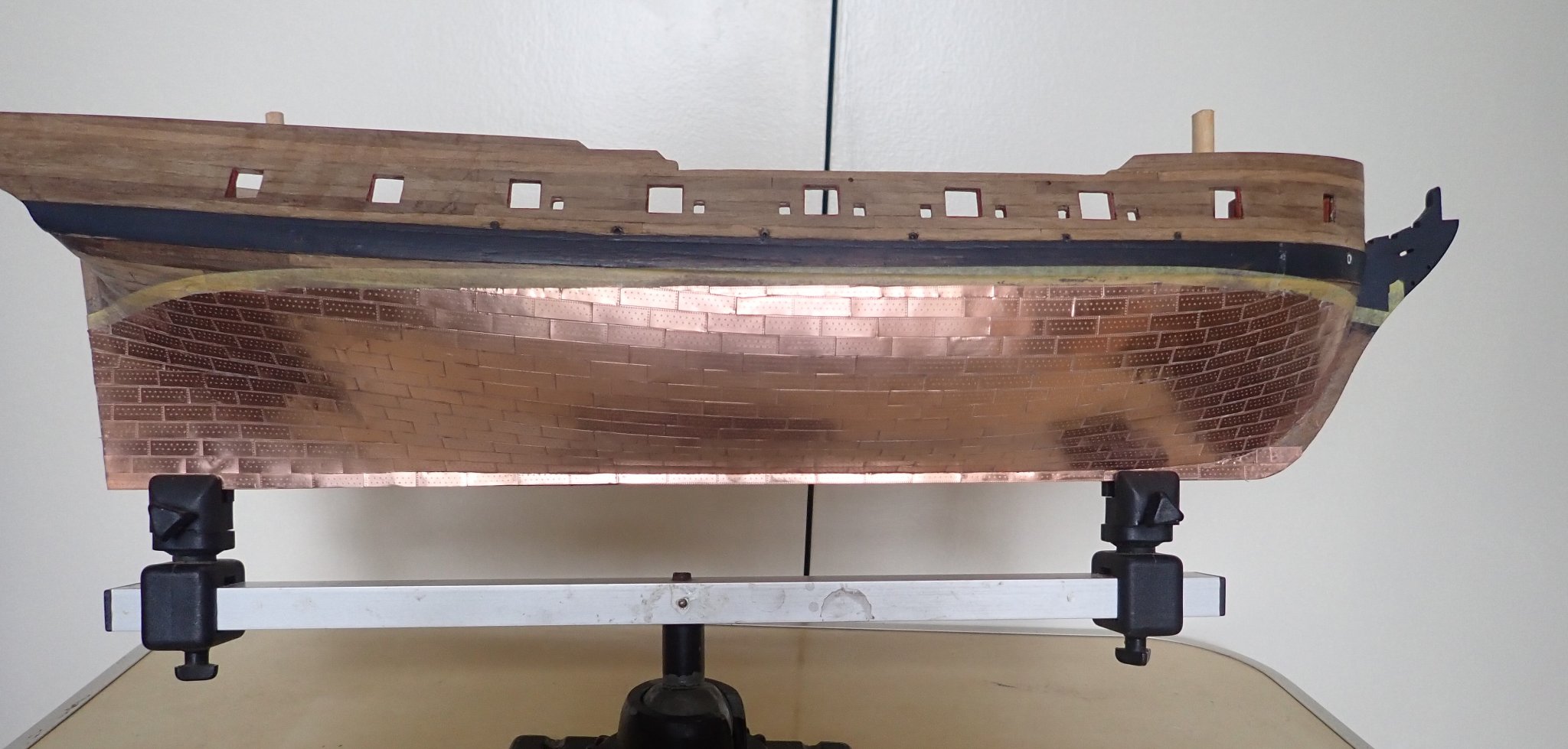
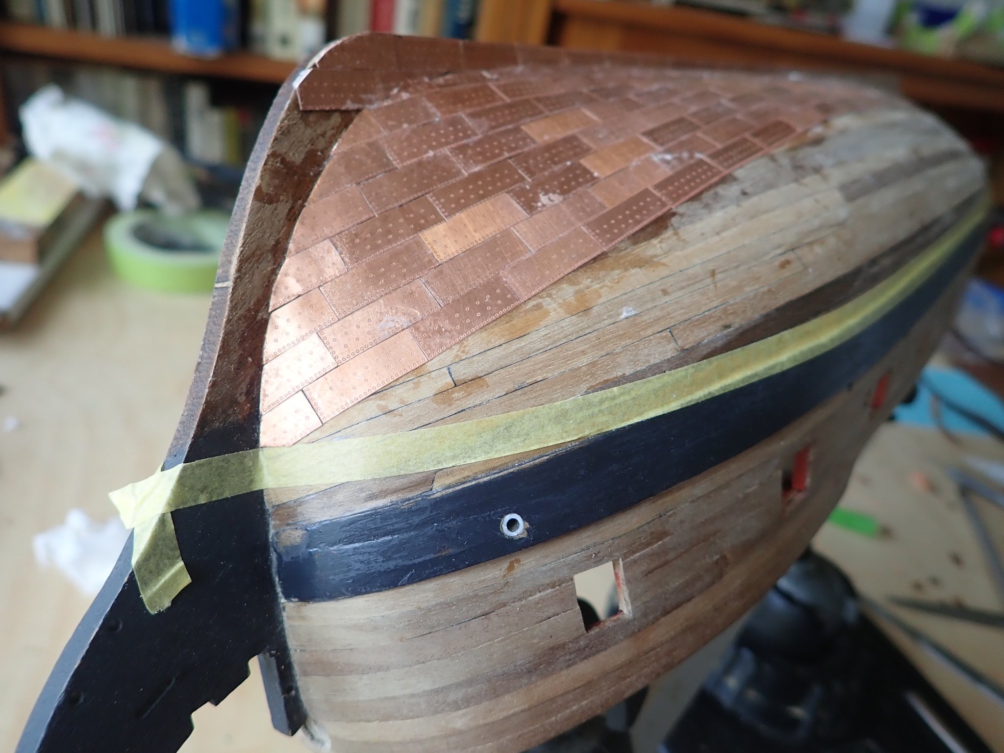
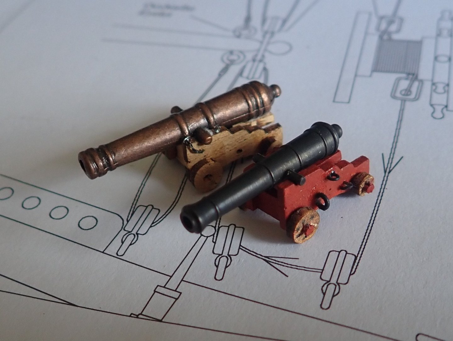
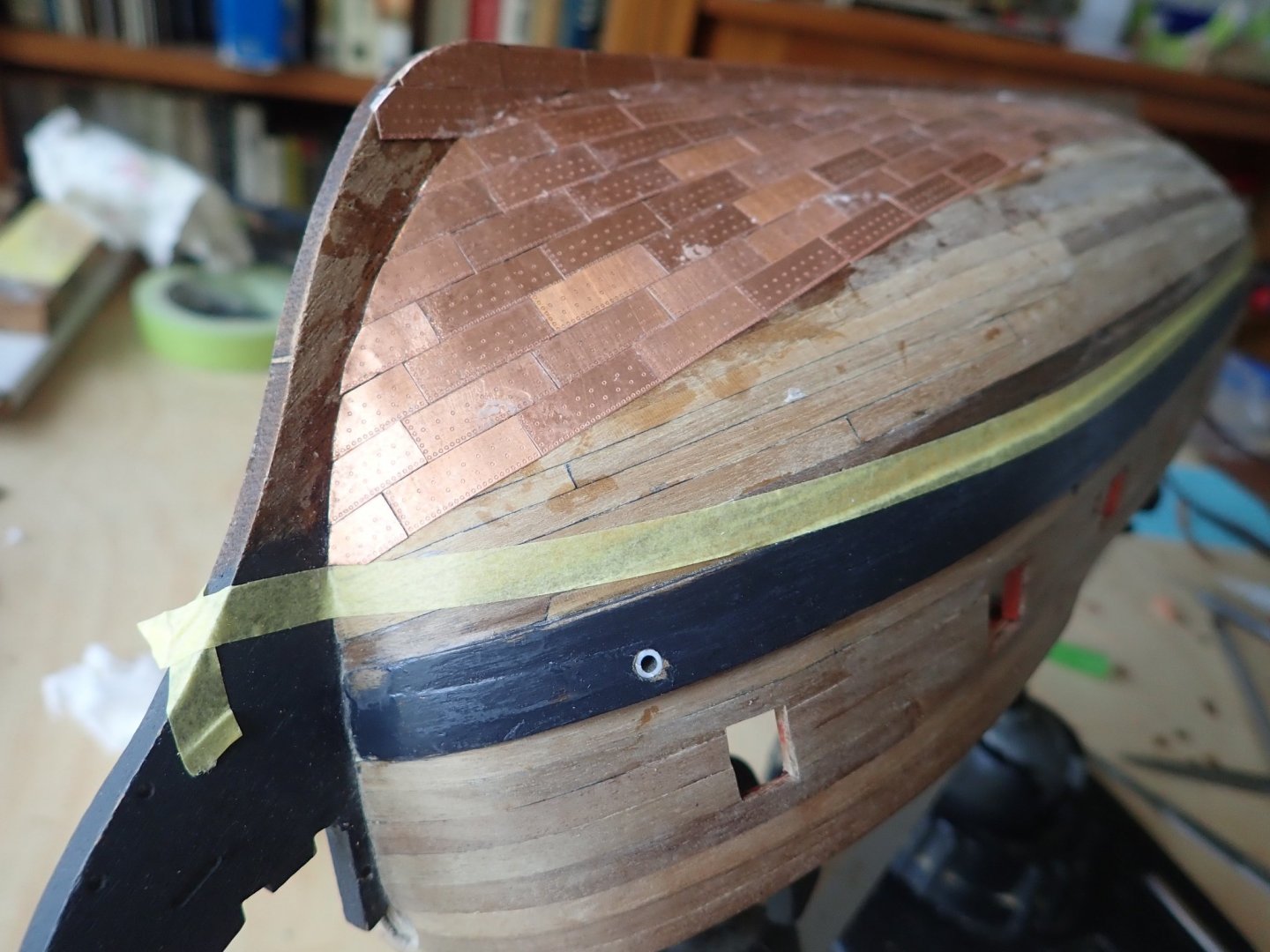
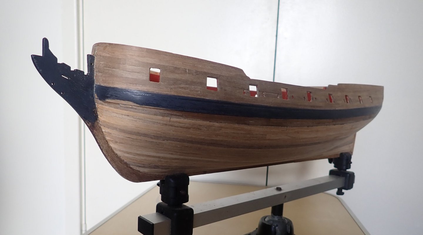
Progress has been slow, partly because I keep thinking about what to do, rather than doing it. I masked the hull, mainly to provide bare wood to which the trim strips will be glued - I have a dislike of gluing anything to something that has been painted. I’m never confident of the glue adhering well to the paint. The hull was painted and the trim strips glued in place. The two lengths of bare wood can be seen. The strip that runs through the gunports was applied in one length then trimmed where it was in way of the ports. (The patterns visible on the copper are reflections, not tarnish). Also visible in the photo is the quarter light, in place but not yet fixed. This was previously located using a card template, and two holes for thin dowels were drilled to ensure later accurate positioning. I didn't notice at the time, but the quarter light is slightly too high - so much for accurate positioning - and had to be moved down a couple of mm. The next major job is the guns. Like many, I was dissatisfied with the barrels that were supplied in the kit, and I bought new ones from RB Models (thanks B.E.). The kit barrel and the RB barrel. These were dressed with monograms from Syren. The monograms came in a sheet of black laser board (I believe it’s called), and the scrap was cut into small squares and glued to the barrels to represent the touch holes. Admittedly neither the monogram nor the touch hole is visible from any sort of distance, but I know they are there (they're not on the barrel in the above photo). The carriages were built as per the kit with some additions. At the moment the cannons are still being assembled, so no photos yet. Except for the trial cannon, that I have been using to sort out various things. I’m going to rig the cannons with breech ropes and I’ve decided to rig the training tackle as frapped. This will be done off ship. A simple jig was used to hold things while I seized the breech ropes to the ring bolts. The photo shows the trial cannon with the breech ropes, and my first attempt at frapping. It also shows the monogram and the touch hole (somewhat off-centre, unfortunately). The breech rope is 0.88mm from Syren (no longer available of course), the training tackle rope is 0.10 (Amati), the blocks are 2mm from Vanguard and the hooks are 2.5mm from Crafty Sailor. So that’s it for now. Cheers


- 104 replies
-
- 4
-
-
- pegasus
- victory models
- (and 2 more)
-
I totally agree 🙂. Though the next somewhat drawnout job will be the cannons, thankfully only 16.
-
Great job on the lantern Tim. I've also got one of Chuck's kits, but it will be awhile before I need to build it.
- 164 replies
-
- 1
-
-
- fly
- Victory Models
- (and 4 more)
-
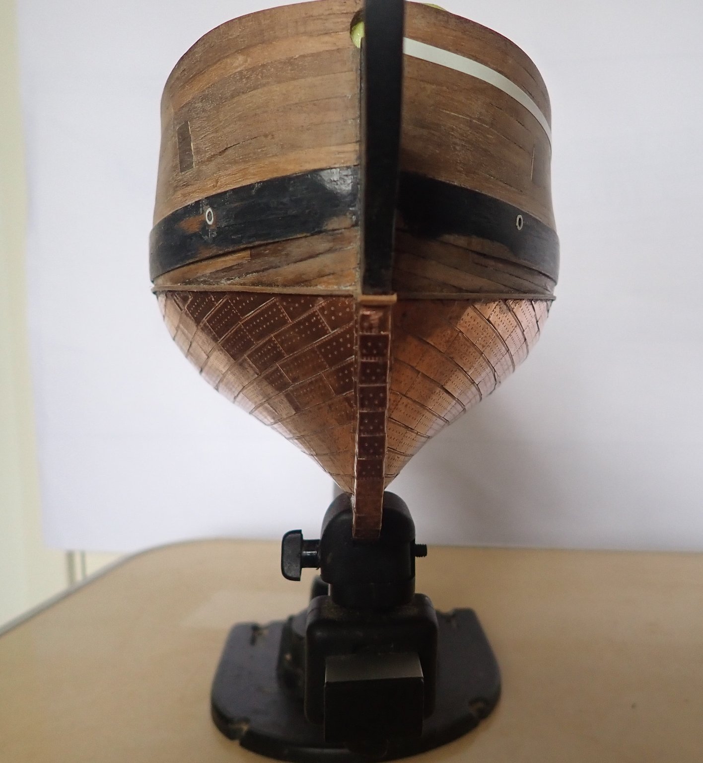
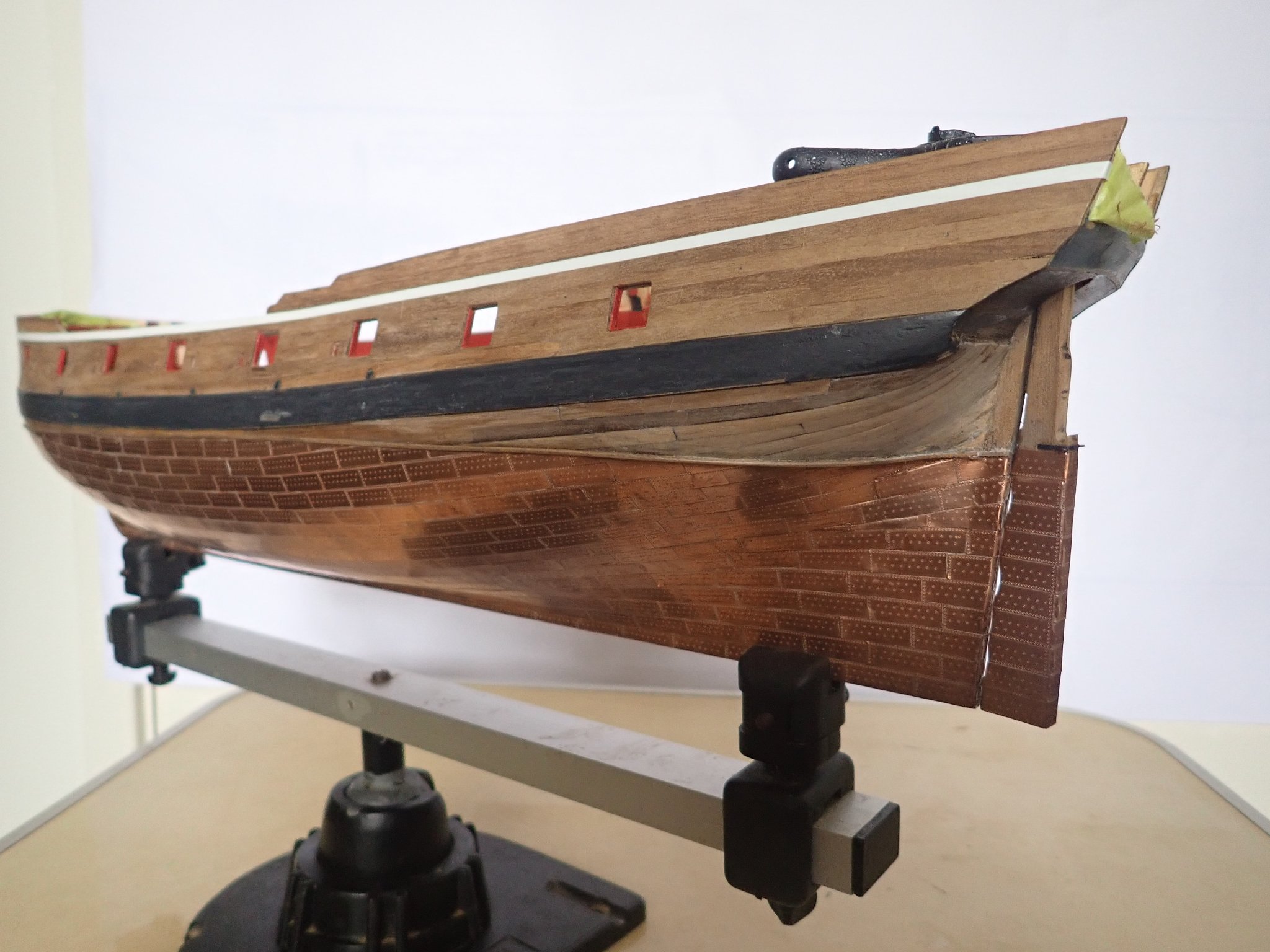
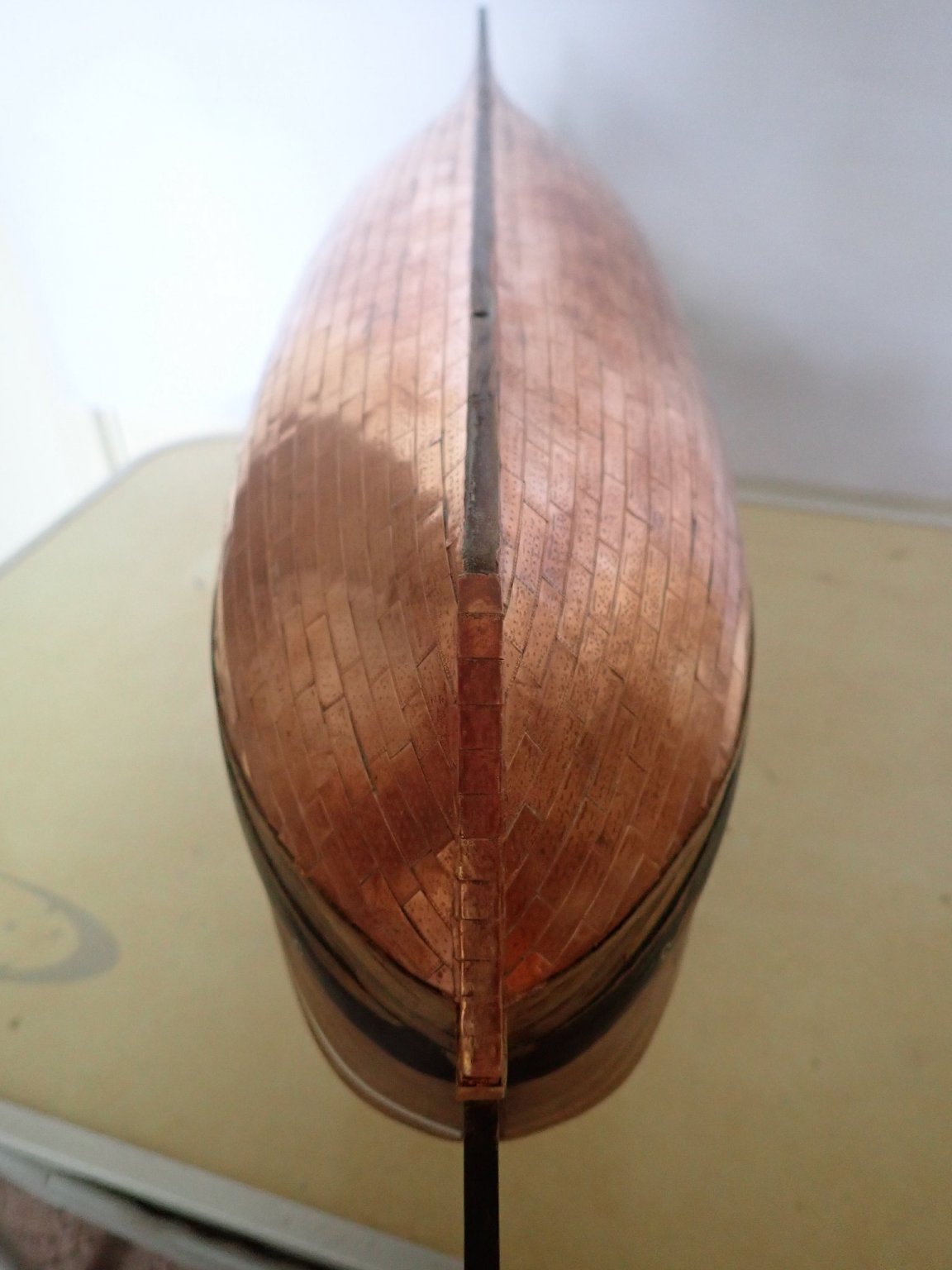
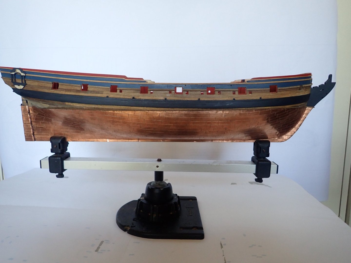
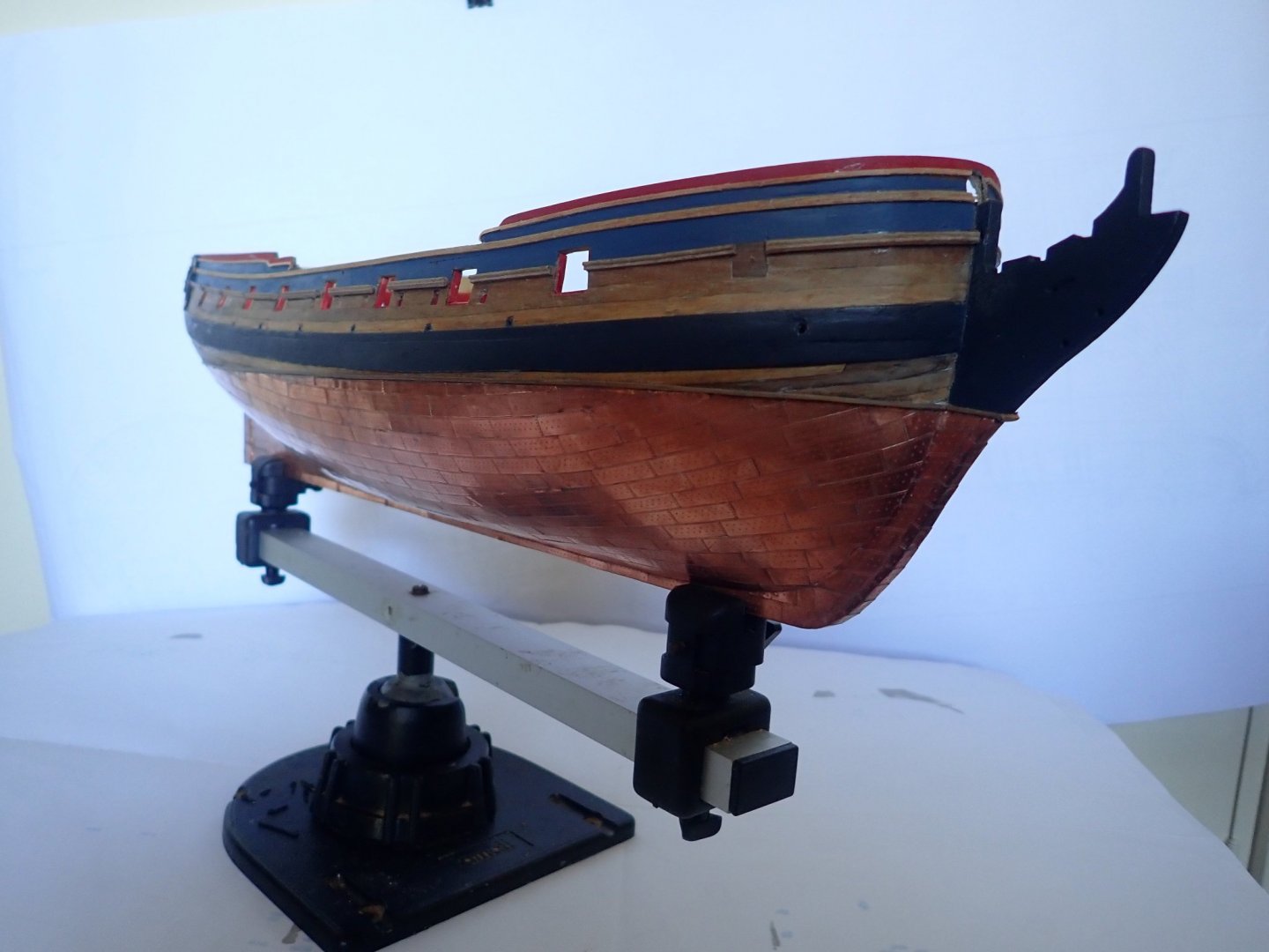
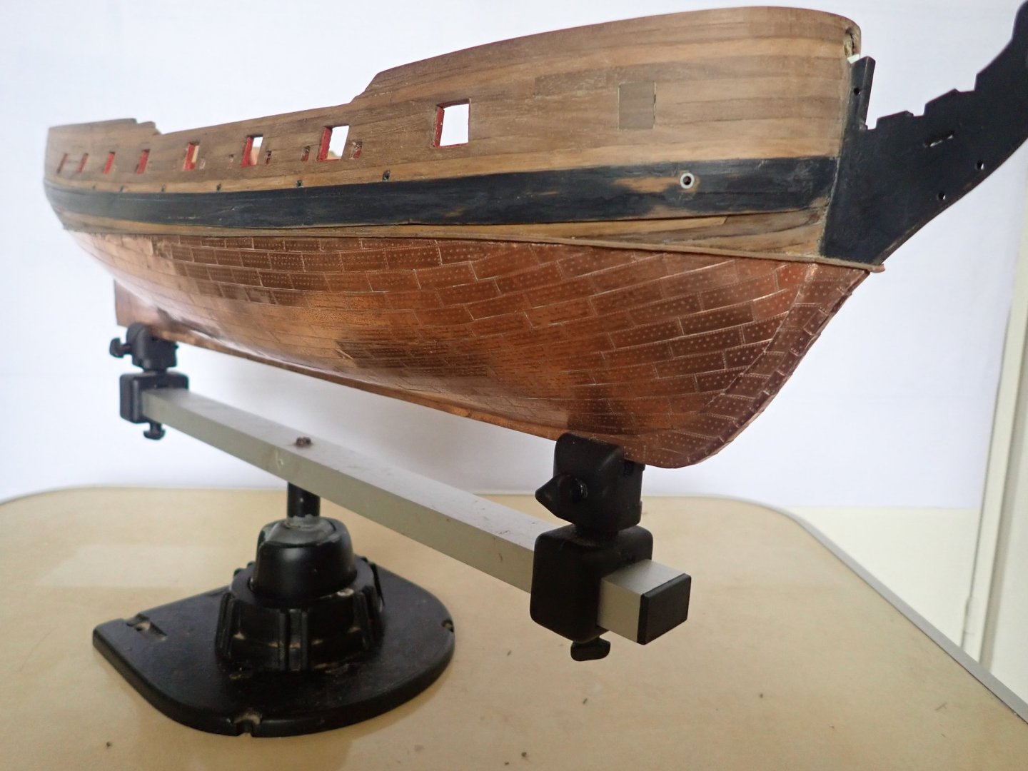
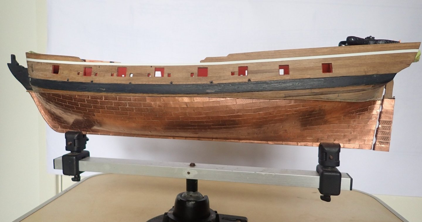
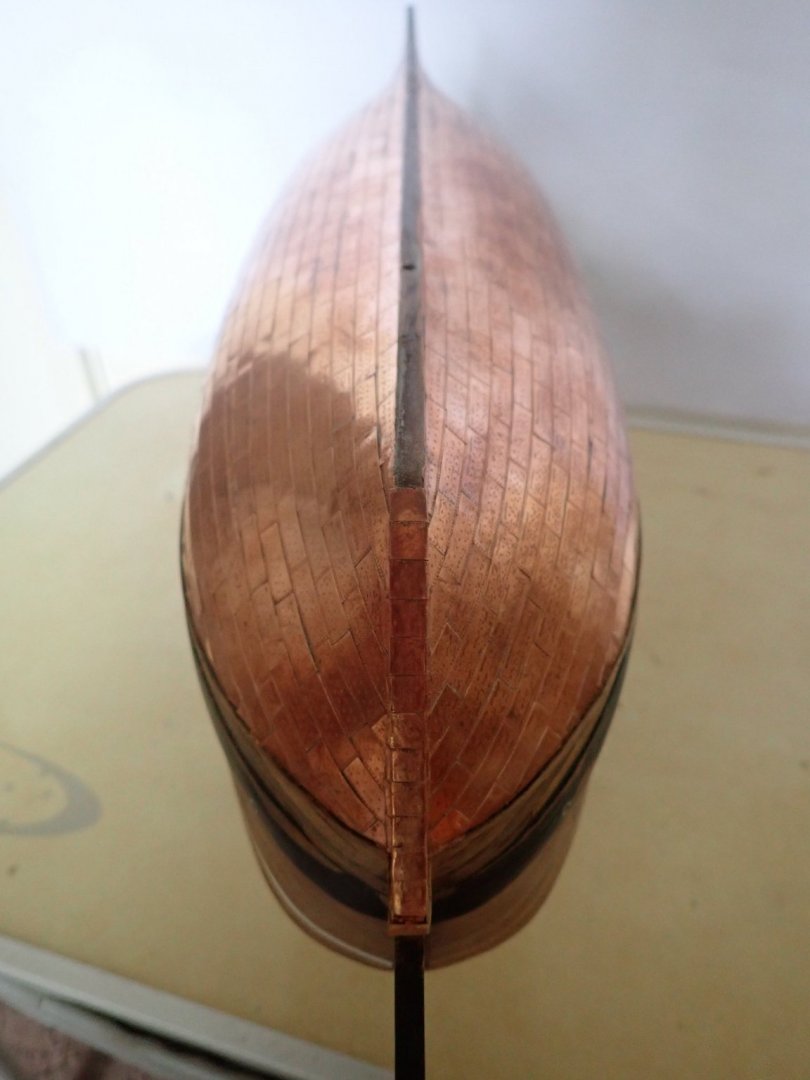
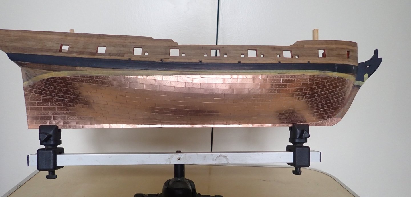
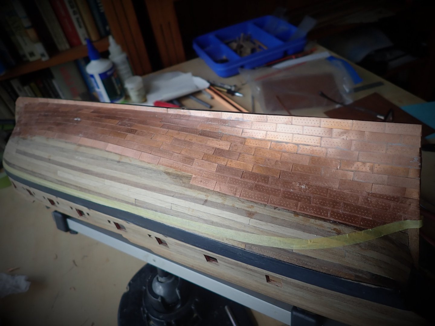
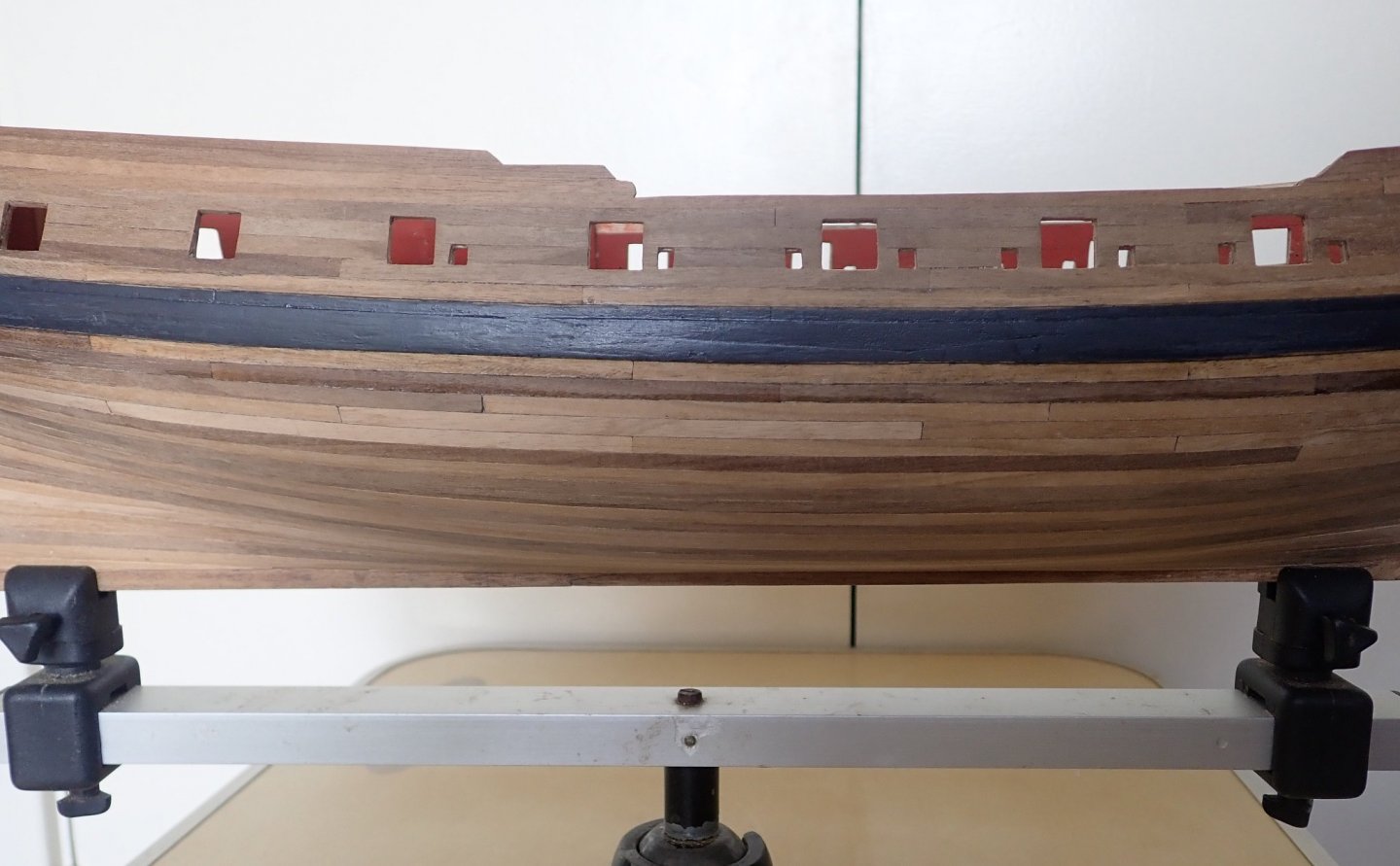
Not much to comment on. The coppering is finished. I don’t know that I’d copper another hull. I did copper the Bellona (link below), but I cheated for that. The white tape is in place ready for painting of the hull. The wale is showing definite signs of needing touching up, which will be done shortly. The rudder is in place but not mounted. Cheers


- 104 replies
-
- 1
-
-
- pegasus
- victory models
- (and 2 more)
-
What were your first tools as a child?
Richard44 replied to FlyingFish's topic in Modeling tools and Workshop Equipment
The first tool I ever had ( I was less than10) when making balsa model aircraft was a double edge razor blade pinched from Dad. The tips of my fingers took a battering! -
Hi Terry, I've attached a pdf file that shows the plan of the stove - this has been taken from TFFM with Greg's permission (one of the authors). The original scale of the plan was 1:48, I have no idea just what the scale is now after scanning, but I added a scale bar (in cm) so you should be able to work out the actual dimensions you need. Cheers Pegasus stove.pdf
- 366 replies
-
- 1
-
-
- pegasus
- victory models
- (and 2 more)
-
Thanks for the comments Tim and B.E. and for the “like” Kurt. The starboard side has been completed and cleaned using acetone and very fine steel wool. There is still some cleaning up to do. The stem will be finished once the port side is done. The waterline (tape) looks to be way off at the stern, but it’s simply the angle at which the photo was taken. It was actually difficult to get a decent photo due to the glare off the newly cleaned copper. I didn’t have any real problems doing the coppering, though there were quite a few plates removed and scrapped as they didn’t go onto the hull correctly. Even so, I have 100 plates left over. A bit of a rest and then onto the port side. Cheers
- 104 replies
-
- 5
-
-
- pegasus
- victory models
- (and 2 more)
-
The plates came that way Tim.
-
For a first time builder, you're doing extremely well. You should be very happy with how the build is going. Cheers
- 164 replies
-
- 1
-
-
- fly
- Victory Models
- (and 4 more)
-
Onto the coppering. Slow and tedious. You can really fix only one plate at a time, instead of a string of three or four. The limiting factor being a race between you positioning the plates and the CA going off without the plates being where they should be - I tried to do this and lost. So plate-by-plate, although there are some places where there is time to position two plates that are still linked. Scissors were used to trim the plates when required. The white patches on the plates in the photos are pieces of rubber gloves, CA bonds to these with a speed that is unbelievable. No attempt has yet been made to clean the plates, I'll do this when the coppering is finished. The white circle in the photo below is the scupper coming from the manger. It will be painted when I get around to touching up the wale. The tape marks the waterline. Back to the coppering. 🙂 Cheers
- 104 replies
-
- 4
-
-
- pegasus
- victory models
- (and 2 more)
-
Hi Tim, These are the ones I bought to replace the Amati ones. But like the ones B.E. bought, they are not complete - barrels only. You'll have to make up yokes for them. Your ship is looking really good. Well done on adding the elm tree brake pumps, these make a nice easy addition. Cheers
- 164 replies
-
- 1
-

-
- fly
- Victory Models
- (and 4 more)
-
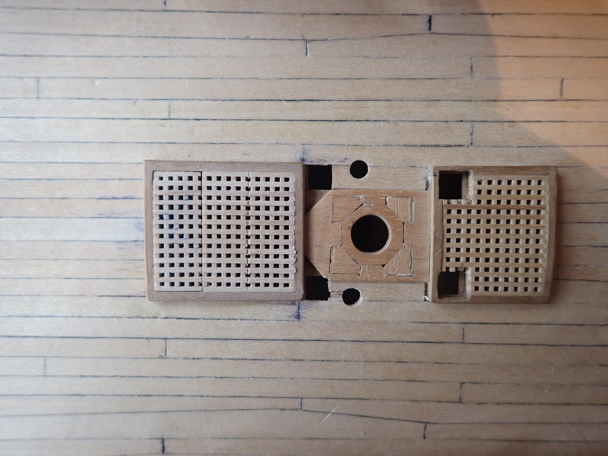
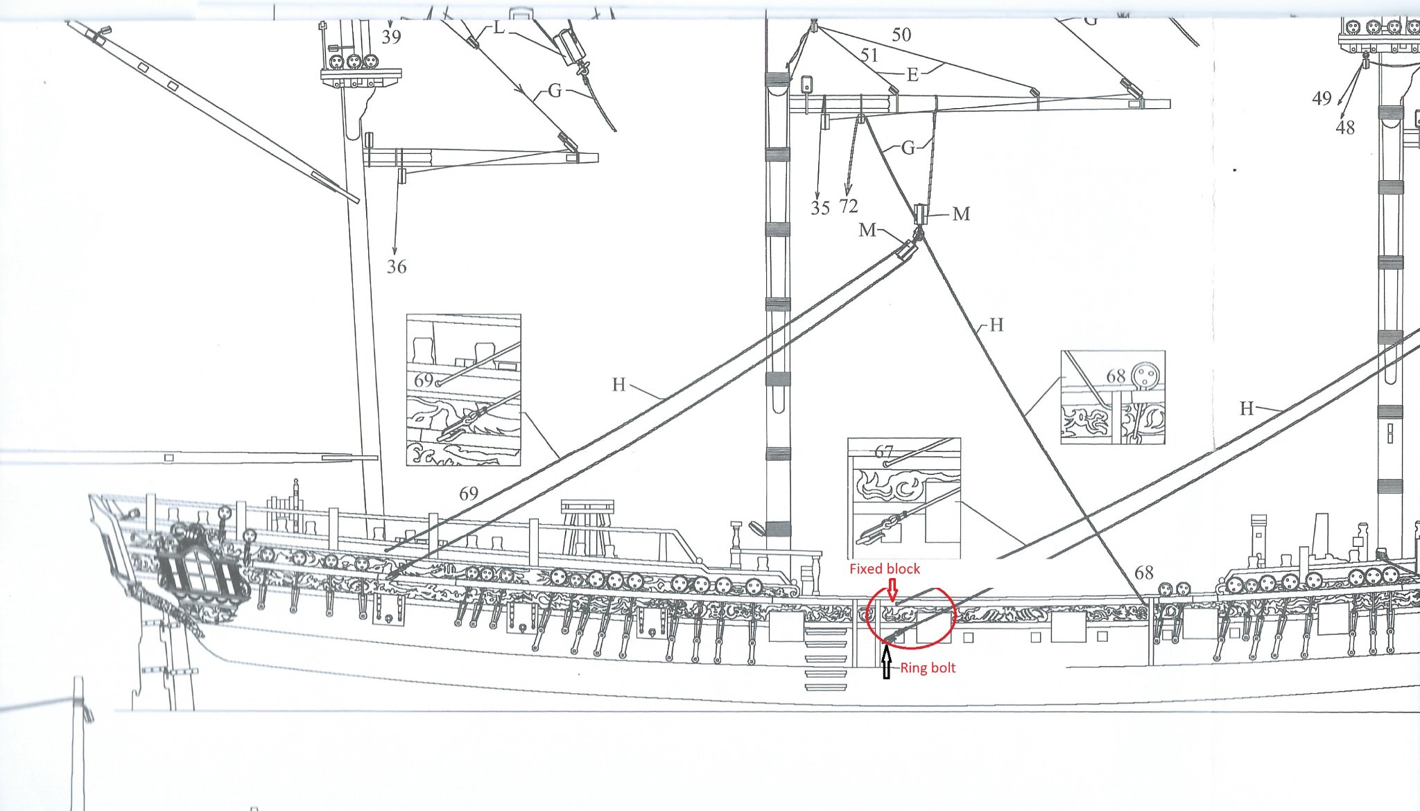
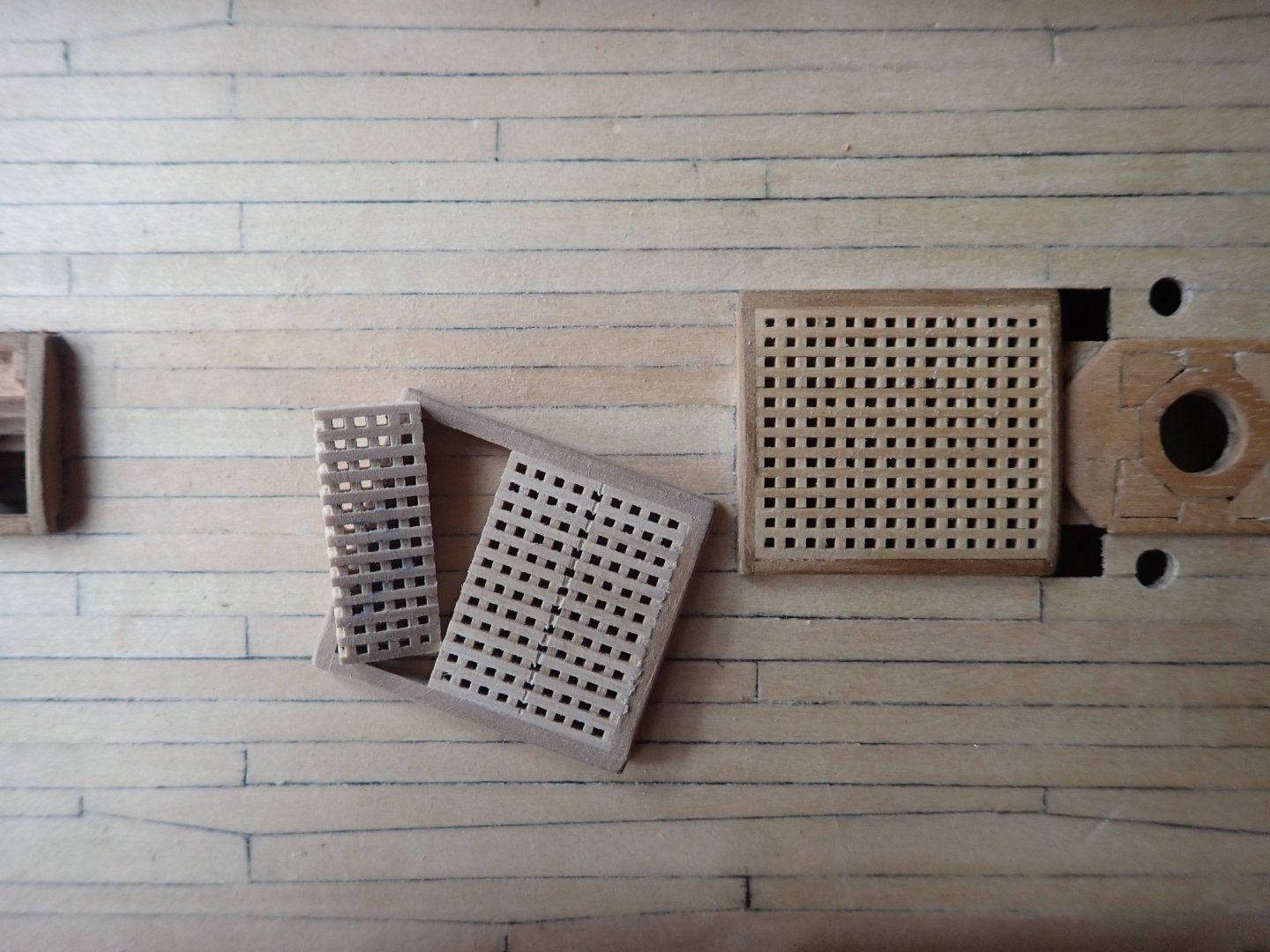
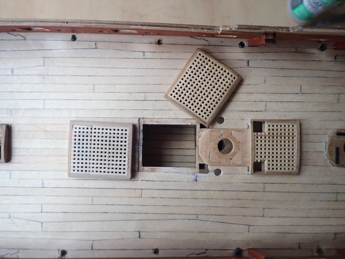
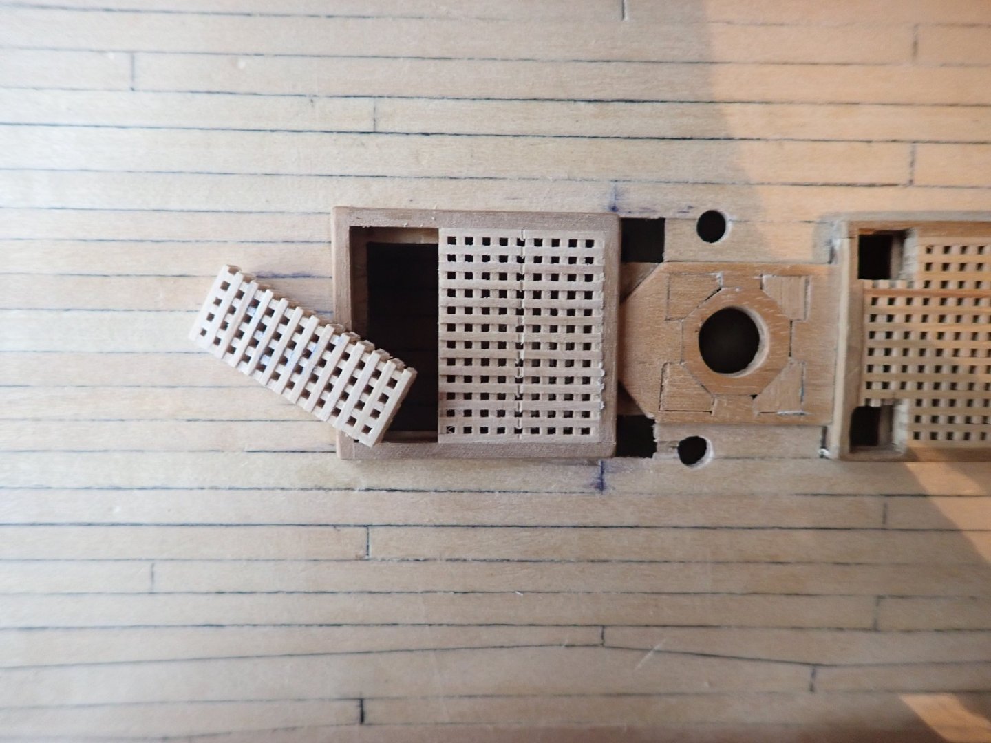
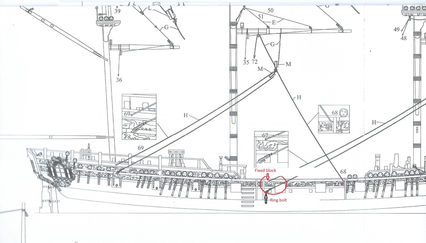
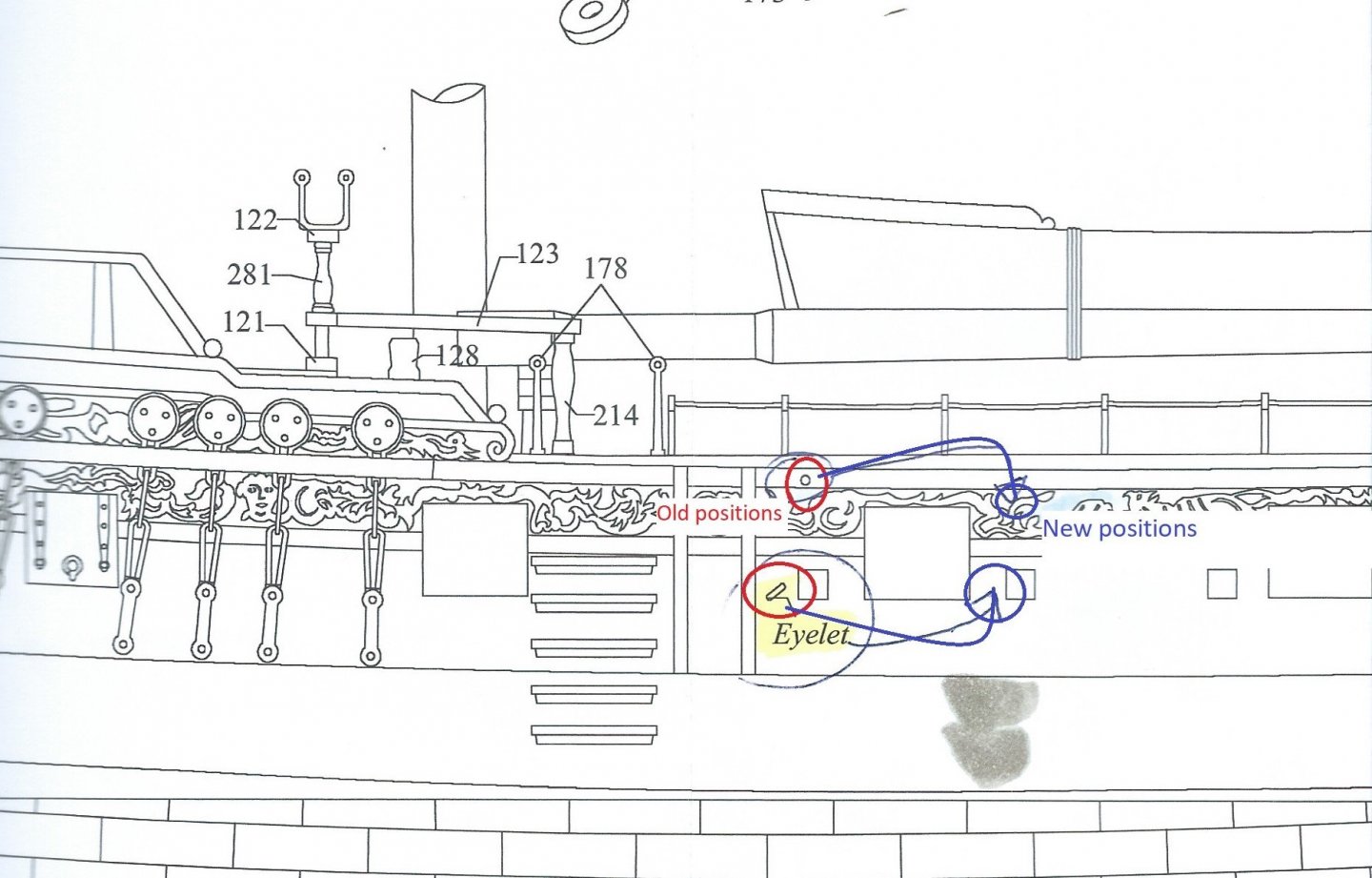
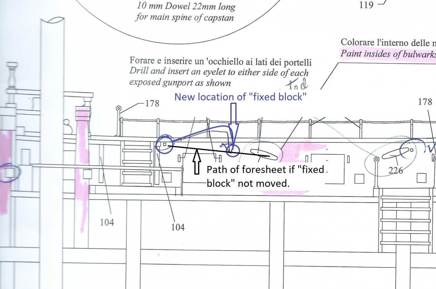
As I mentioned in my last post, I had a few small jobs to do before starting the coppering. The first involved the anchor cables about which I have been puzzling for a while. These are fed from the anchors through the hawse holes, but then what? The kit plans and instructions are no help at all. The TFFM gave me the clues I needed, and I should point out here that I have the original Practicum, not the more recently published books which may contain more information. Antscherl says in the TFFM text that there are stopper bolts on the deck which secure the anchor cables by using short lines called “stoppers”. The deckplan shows five of these from the fore hatch to the main hatch, and these also do double duty as attachment points for the relieving tackle of the guns. The kit plans show only three in the same area, immediately behind the guns, just for the relieving tackle. So the cables come aft from the hawse holes, past the fore hatch and as far as the main hatch. They then need to be fed below decks for storage, presumably through the main hatch. The TFFM says the grating for the main hatch is in three parts, and I have therefore assumed that the foremost section of the grating is lifted free to allow for the cables to be run through the hatch and stored below. Out of curiosity, I checked the build logs of others that I had bookmarked to see what they had done. Only one of those I looked at did what I have described above - Blue Ensign’s build. So my immediate problem now is that I made and installed the grating of the main hatch in one piece quite some time ago. If I want to run the cables through to and down the main hatch, there is only one thing to do - remove the grating and build a new one. Time for a deep breath and trust that I can remove the old one with minimal damage. I used some isopropyl alcohol to soften the PVA, being aware that this will cause some bleeding of the permanent marker that I used to simulate the caulking of the deck planks (I tried it on a test piece). The grating came off relatively cleanly with only some minor bleeding. The old grating still in place and its replacement. The old grating removed. The new grating in place. Whilst looking at one of the rigging plans, I noticed that the foresheets were led directly across one of the gunports on the outside of the hull, then were belayed to a cleat on the bulwark which meant that they were again led across the gunport, this time on the inside of the hull. This didn’t seem like good practice to me, as there would clearly be a risk of the sheet being severed when the gun was fired. On the model, the sheet is led through a hole (a fixed block in reality) in the bulwark then goes forward to the cleat. Importantly, in the TFFM, the block is located on the other side of the gunport, so the sheet is completely clear of the port. The rigging plan showing the locations of the gunport, the foresheet running across the port, and the fixed block (the hole through the bulwark). The positions on the kit plans of the hole and the eyelet are shown in red and the new positions in blue. The inside of the bulwark showing the new location of the fixed block (the hole through the bulwark) and the run of the foresheet across the top of the gunport, if the fixed block was not moved. That's it for now. Cheers

- 104 replies
-
- 3
-
-
- pegasus
- victory models
- (and 2 more)
-
You're making wonderful progress Eugenio, you must be happy with how the Victory is going.
-
You can't adjust the speed of the Proxxon. This has never been an issue when sanding wood, but could be if it is used on a plastic model. Edit. Oops. The Proxxon has a choice of two power packs - one of them allows the speed of the tool to be adjusted. 🥴
-
I have a Proxxon pen sander and can highly recommend it. This is my second one, the first lasted for 20 years or so. As Mark said, these tools are not designed for bulk removal of wood, but I have just used mine to fine sand the second planking on the hull of my Pegasus build. Cheers
-
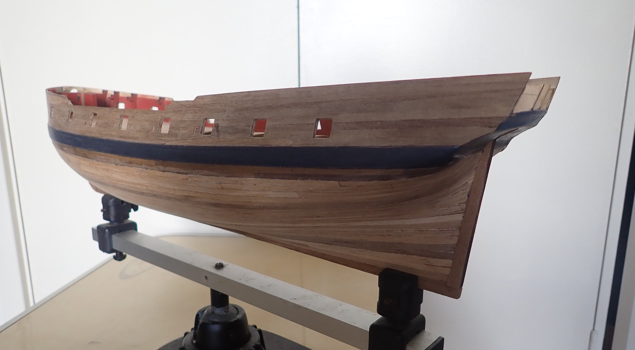
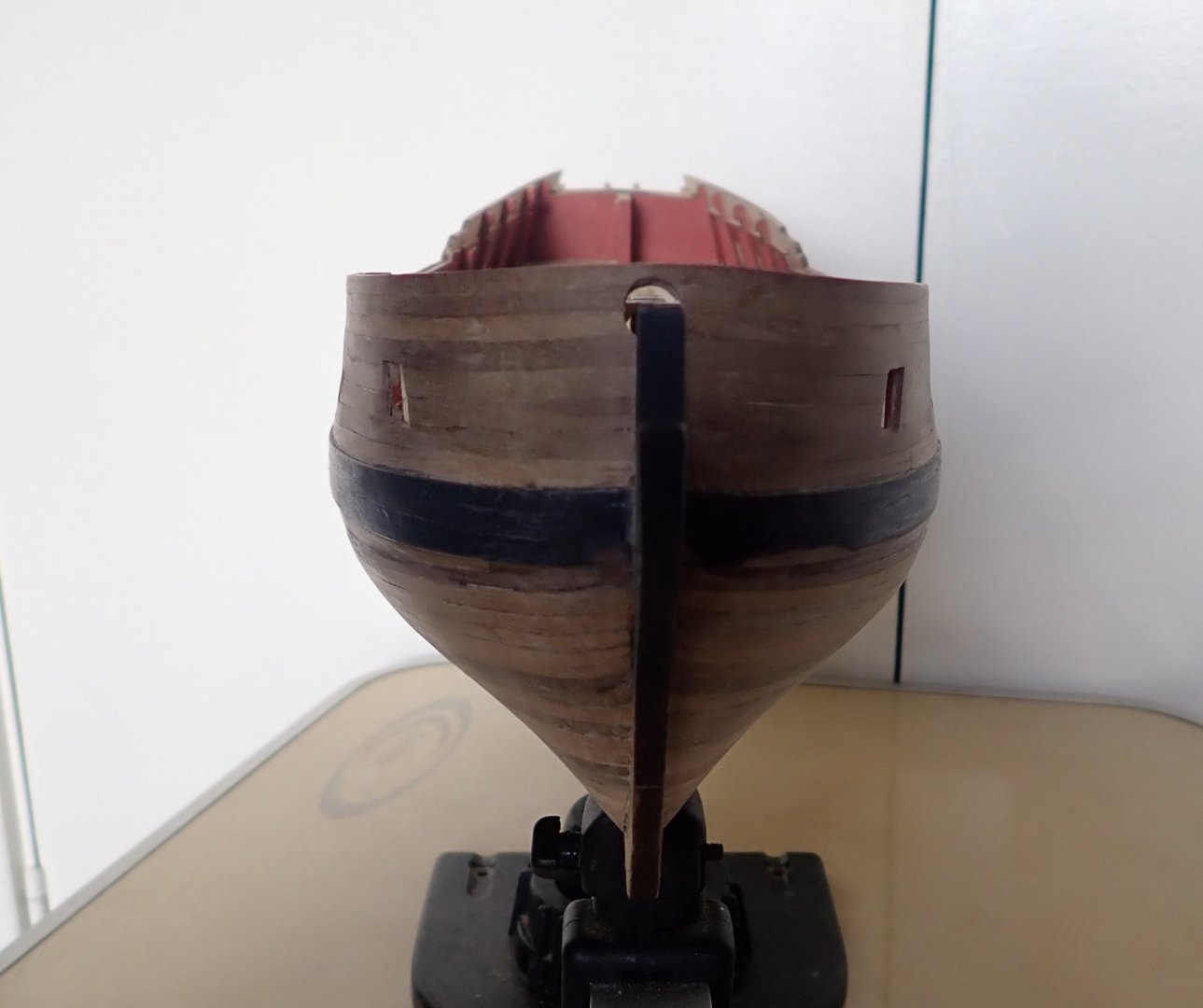
The second layer of planking is finally complete!😊. It took quite a while with numerous interruptions including making two small boats (link below). Scale length planks were used below the wale to just below the waterline, and full length planks below that as I intend to copper the hull. The planking below the waterline is not as neat in some places as I would have liked, but it will be covered. There is still some sanding to do, and quite a bit of touching up of the painted areas. A moulding has yet to be fixed between the lower counter and the planks. A few small jobs first then onto coppering - should be fun 🥴. Cheers


- 104 replies
-
- 3
-
-
- pegasus
- victory models
- (and 2 more)
-
Thanks for your comments James. Yes, some swearing was involved especially when I dropped one of the knees (that go on the thwarts) onto brown pile carpet 😬😬. It took me about 20 minutes to find it, using a torch held at a low angle - probably could have made a new one in the same time. Cheers