
DONATION DRIVE - SUPPORT MSW - DO YOUR PART TO KEEP THIS GREAT FORUM GOING!
×


Egilman
-
Posts
4,379 -
Joined
-
Last visited
Content Type
Profiles
Forums
Gallery
Events
Everything posted by Egilman
-
 Yeah, I'm learning brother.... I went ahead and look for some replacements for the Sky Lookout equipment on chance that one of the AM companies would make a replacement.... I found one, the only one..... And it's only available from Hobbylink Japan.... But from looking at it they are much nicer than the original Dragon design and more accurate to boot.... And it gives me 10 of them which I will need for several of my TF-18 builds.... And I get the early war target designators and closed pelorus's as well.... Will take a couple of weeks to get here, but at least I have a solution.....
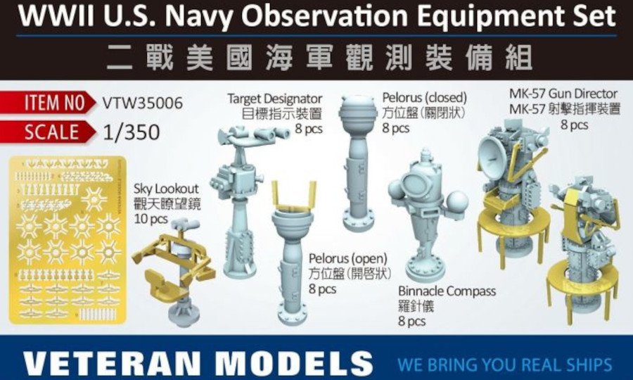
-
Well, Thanks Mike, WE are kinda self regulating in this manner, build logs should be about the subject build and it's details and issues.... The early war disaster that was the Mk-14 torpedo was has nothing to do with Japanese destroyers.... Sometimes I need to be reminded of such, I can drop into discussions over disparate subjects way too easily sometimes.... Unfortunately there is no area here to discuss such things and it isn't appropriate anyway for a forum devoted to ship modeling.... At times I need reminding of this.... EG
-
Your absolutely right, and I apologize to Mike for straying off the topic.... This isn't the place for a discussion over torpedo effectiveness and reputation..... Sorry...
-
I found another reference to the US Navy's interest in Italian torpedoes in WWII.... Regia Marina Italiana Weapons; Torpedoes This covers the torpedoes in use by the Italian Navy during WWII, at the bottom it mentions the US Navy's strong interest in them... It's not definitive true, but it backs up what Ike wrote in his Memoirs.... Still looking for more... EG
-
Thanks Lou for the suggestion, I always love reading the experiences of people who were there.... I've obtained a copy and will be perusing it's pages shortly.... In the meantime, I would suggest two items.... NUSC Technical Document 5436 15 September 1978 A Brief History of U.S. Navy Torpedo Development (pdf) E. W Jolie Weapon Systems Department Naval Underwater Systems Center Newport Laboratory Basically I'm posting it here for everyone I'm sure you know most of this info already.... and.... From "US Navy Bureau of Ordinance In WWII" Chapter 6; Torpedoes... This is an extensive report on the torpedoes used by the US Navy in WWII, their origins, their designs, their improvements, and their battle history.... (in minute detail all the way to the point of both King and Nimitz ordering the deactivation of the magnetic exploders on all the Mk 14 torpedo in use at that time) One thing it notes, the US Mk 14 & Mk 18 Torpedoes were the most successful submarine naval torpedoes used during the war, (by an order of magnitude over anyone else's) they were the only torpedoes used in combat on our submarines during the war..... Yes they had a very well earned bad reputation early in the war and it goes into the truth as to why this came about, the results and actions taken to overcome it, (It was a rep that never really went away) And how they never fully fixed it's reputation, by 1944 they had mostly eliminated the problems technically..... By 1944, the reputation of them got so bad and the exaggeration of that rep by the crews and officers using them making it worse every day, casts every anecdotal report of their performance in question... Especially from late in the war especially after solutions were found and implemented, which gets very short shrift in the anecdotal re-telling..... As far as the Mk 18 torpedo being a copy of the German G7e, the Mk 18 was a Mk 14 using a Newport/GE designed electric motor for propulsion on the same principle as the German design, it's main claim to fame is no wake.... (they first obtained a G7e from a captured U-boat in mid '42 according to the Bureau of Ordinance) My information on the Italian Mk-18 torpedo and the Navy's desire for an example comes from studying the negotiations for the Italian surrender during WWII, it's was prominent in those negotiations they really wanted the guidance system for examination as it was claimed to be the most consistently accurate of the pre-war systems.... (interesting that it isn't even mentioned in the Ordinance report on US torpedo development) It was such a prominent feature of the surrender negotiations that General/President Eisenhower wrote about it in one of his memoirs...... (reading it in his memoirs is what prompted me to research the surrender) As always brother I appreciate the suggestions for further reading, keep them coming my friend.... As far as the details I'll let you all read it for yourself...... so you all can develop your own opinions and not take mine as rote.... The Ordinance report does cover the bad rep in detail, it's valid beginnings and it's exaggerations and propagation amongst the crews and personnel as the war progressed even after they reduced most of it problems.... A need to read as it gives a needed factual perspective to counterbalance the perceived hate of faulty equipment..... (much like the Sherman tank hatred espoused by those that don't like facts) Statistically, the Mk 14 and it's derivative Mk 18 were the most successful torpedoes of the war, in anyone's navy.....
-
It's really hard to put down a thin consistent coat with rattlecans, you have to spray so far away from the object you lose half the can to overspray at times....
-
Yeah we had a real problem there for the first year and a half of the war, it wasn't the torpedo itself, guidance was the main issue, no guarantee that when fired they would go where they were targeted... then the second issue reared it's head, IF they ran correctly, (a big "IF") and happened to strike a target, there was a 40% chance they would fail to detonate.... (even with the failure to detonate problem, if they had ran straight and accurate, many many more Japanese ships would have been sent to the bottom a lot earlier in the war than they actually were) All that changed with the The Armistice of Cassibile September 3rd '43, the Italians surrendered and the Regia Marina's agreement to surrender themselves to the allies rather than be taken by the Germans, they brought with them the Mk 18 torpedo, or more important it's guidance system... It was specifically mentioned in the negotiations that the US Navy wanted it.... They turned it over when they surrendered at Malta... It was adapted to US Navy torpedoes by February 1944, You hear no reports of serious issues with our torpedoes after that..... The early war disaster that our torpedoes were, was a closely held military secret.... Every bit as tight a secret as Ultra, The Manhattan project, UHF Radar and the Mark 24 mine.....
-
The Long Lance torpedo was right up there in effectiveness department.... was considered the second best torpedo design pre WWII behind the Italian Mk 18..... What made them most effective though was the Japanese tactical usage of them.... They viewed a torpedo as a one shot weapon, use it before you lose it.... so their tactical doctrine called for them being fired before they went into a general gunfire battle.... (ie, once your in a gun battle it's next to impossible to do the precise maneuvering necessary for effective torpedo attack, as the US Navy learned to serious effect) The Japanese would formulate their battle plan so they would fire their torpedoes at the start of the battle guesstimating the maneuvers of the enemy once the engagement started..... They would shoot their torpedoes at where the enemy ships would be or would have to go to, (once the gun battle started) from long range...... Gun battles using optical gun control necessitated closing the range as quickly as possible, either crossing the "T" or bringing the battle line closer together so the guns would be at their most effective range... Direct approach to the target, and turn one way or the other..... In close quarters where maneuvering is restricted by shore lines and shoals the enemy's movement can be predicted given the positions of the ships and the prevalent tactics used at the time... The Japanese, using their tactical doctrine, would fire at where the ships had to go.... A huge tactical advantage with a torpedo that could range out to 25k yards, (outer limit of gun range for cruisers) This doctrine was devastating in the battles around Savo Island and throughout the Guadalcanal campaign.... In several battles, our heavy cruiser battle lines were pretty much disabled before they could really get into effective gun range allowing the Japanese to destroy them with shellfire...... Most of our torpedoes, (Destroyers & Cruisers) went down with their ships... Later in the war, it was less effective cause we had learned that closing quickly was not the right tactic, backing off and bringing in aircraft was the right tactic.... Hard lessons learned.....
-
Yeah, that's one way, and if the kit is split along the waterline, you can get a real good result for fairly flat seas.... But what I've found if you want to do any serious seaway above dead flat, you need a full hull... This is why I use the carve the hull into the foam technique.... You can model an active seaway in this manner..... Smaller ships look better in non-smooth water, especially a destroyer with a bone in it's teeth chasing a sub, or making a high speed torpedo pass.... It does make the base deeper, but the trade off is a more defined seaway imparting action in it's natural environment... Imagine the Tamaroa in 90 ft seas.... No one's done that yet that I know of.... Or the SS Pendleton and Fort Mercer rescues in 70 foot seas.... (USCGC Acushnet WMEC-167 for the Fort Mercer rescue) Those are extremes I know, but it proves one thing, you need a full hull to do seaways in action, no matter the size of the ship....
-
Yep, pretty typical of all these ships where there is a plethora of conflicting information, they had to make some choices and they seldom get it completely right..... But they try.... At least we have the basic ship in hopefully the correct configuration for some of it life.... Some manufacturers/designers can't even get the basic hull shape correct....
-
Sad to say this is the case, lotsa great kits have been lost over the years in just this way..... Life moves on.....
- 1,090 replies
-
- 6
-

-

-
- showcase models
- vendetta
- (and 2 more)
-
She was painted in admiralty dazzle when she left the NY yard in '42, and remained that way throughout the war all the way up to her going to the breakers, her dazzle was repainted twice during the war, so faded is good, lotsa rust is not...... Faded, chalked with hints of rust around a few edges would be a good look... Looks like your almost there... Well done...
-
Nah, I would just botch it up...... beside I have to actually see it to rig it.... But thanks for the complement my friend...
- 179 replies
-
- 5
-
-
- hatsuzakura
- pit road
- (and 2 more)
-
My pleasure brother, it's what we are here for.... What a chart like that and a ordering source does is allow you to grade your rigging on a 1/350th scale warship the same as they do for the wooden 1/48 scale ships.... Like my Gwin, the mast stays are 2 to 2.5 inch cable layed wire rope, about .008 inch in size, while the antennaes are usually 1/2 inch solid aluminum wire... about .0015 inch in scale...... the running rigging is 1/2 to 3/8th inch manila rope so that is where you use the 50 AGW size wire and just under .001 in size makes a 3/8th rope in 1/350th scale... Using wire, you can scale your rigging in 1/200th or 350th scales easy peasy..... I get fine motor winding coil wire cause it is enameled as insulation to prevent shorts, what this allows is you to use inks or very thin paint to color it without issues of the paint sticking..... Mucilage is used to glue it, yes mucilage, the same envelope paste used in decoupage when we were kids in school.....
- 179 replies
-
- 6
-
-
- hatsuzakura
- pit road
- (and 2 more)
-
Showcase Models Aus, has been offline since 2017..... Their website no longer responds to links saying it doesn't exist which means the domain doesn't even exist anymore..... So no, the model kit is no longer manufactured.... Although there are some available on Evil bay.... Get them while you can if you want one.......
- 1,090 replies
-
- 7
-
-
-
- showcase models
- vendetta
- (and 2 more)
-
Amazon is the source, there are several types but you can get almost any gauge you need direct from the manufacturers... Here is an online chart of wire sizes expressed as AWG gauge sizes but lists it's english and metric equivalent sizes.... Wire Chart (you can order directly from them if you want) It's not as expensive as you think, certainly a lot cheaper than buying from hobby suppliers.... The above example, 50 AWG, measures just under a thousandth of an inch and just over .025mm...... I last bought some 44 AWG off amazon, a spool just shy of 10K feet.... For under 20 bucks, at just under 2 thousandths of an inch it will do most rigging for the scales of 1/200 and lower.... and almost two miles of it, most of my general rigging needs are handled....
- 179 replies
-
- 7
-
-
- hatsuzakura
- pit road
- (and 2 more)
-
It's already out there.... https://www.scalemates.com/kits/trumpeter-05632-uss-langley-av-3--1319580 Hobby Link and Hobby search, out if Japan, the US dealers are still doing preorders..... The kit alone is 100.00 US, shipping from Japan? probably 140.00ish or so.... Haven't heard a lot of splash on it on the boards, probably not too many people have it in hand yet...
- 1,090 replies
-
- 6
-
-
- showcase models
- vendetta
- (and 2 more)
-
Gotta agree here, most American beers are horse whizz.... especially the IPA's... But then when I do drink beer (rarely) it's either Henry's PR cold or Millers HL in any temp state as long as it's fresh.... For a good relaxing drink after a hard day, Mike's HL...
- 1,090 replies
-
- 6
-
-
- showcase models
- vendetta
- (and 2 more)
-
That's some fairly small stuff as well, Gold plated tungsten 0.00314961 in diameter, smaller than an average human hair also..... It's used for drawing the toner off cartridges and drums in laser printers...... You never know where your going to source your materials and sometimes it can be surprising....
- 179 replies
-
- 6
-
-
- hatsuzakura
- pit road
- (and 2 more)
-
.047mm is equal to .002in That's two thousandths of an inch, about half the thickness of a piece of paper..... Actually it's a hair smaller than that but who's going to quibble over a ten thousandth of an inch....
- 179 replies
-
- 6
-
-
- hatsuzakura
- pit road
- (and 2 more)
-
Another source of info on WWII British Navy warships.... https://www.pen-and-sword.co.uk/As-detailed-in-the-original-builders-plans/s/126 An excellent detail resource... they are available at many used book resellers...
-
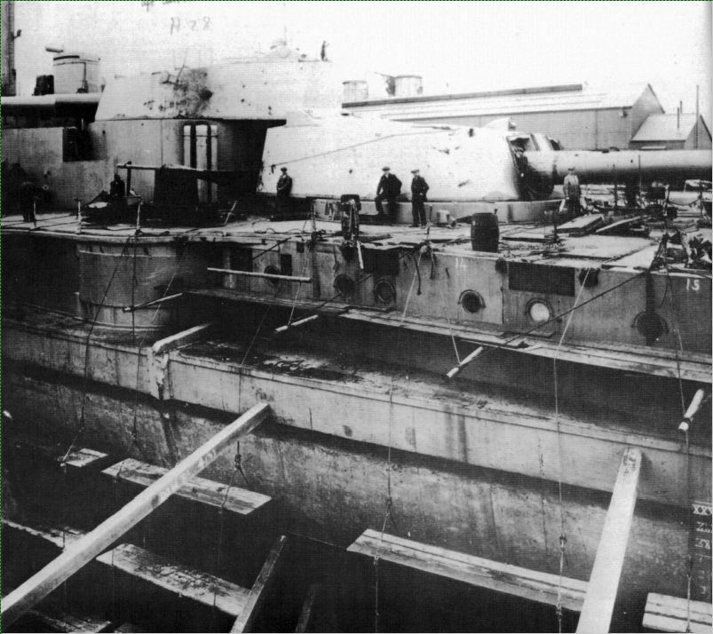
The way the Warspite's hull was constructed, (all the Elizabeth class battleships were) was plates bolted to frames from inside, so there would be no noticeable connections on the outside of the hull, horizontal strakes were laid on the hull consisting of vertical plates butted together and bolted to the individual frames. They alternated strakes, first were laid directly on the frames and the frames were built up between succeeding strakes, subsequent strakes were laid over the existing strakes to form the hull..... Vertical seams were cut to very tight tolerances and packed when bolted to the frames..... They would be hardly noticable .... image from her 1941-42 refit in New York Subsequent improvements to the hull over the years, (like the torpedo bulges installed in her 1924 refit) were welded construction....... As you can see from the image it is hard to pick out the vertical plate joints, they are there but even 50 feet away with a high res camera, (for it's day) they are very hard to see, smaller than the ropes holding up the scaffolding.... (image courtesy of Russ Watton from 'Anatomy of the Ship #35 - The Battleship Warspite' published 1986, Naval Institute Press.... At 1/350th? why bother....
-
Depends on the power of the motor, it can be as thin as under .001"..... the stuff I use is just under .002"....
- 179 replies
-
- 6
-
-
- hatsuzakura
- pit road
- (and 2 more)
-
Your skills are growing brother.... Very impressive on a subject not so often highlighted..... One of the good things about Heller & Tamiya, they did cover many off the wall subjects you won't find anywhere else..... Well done...
-
Mechanical Solar System by jim_smits - Eaglemoss
Egilman replied to jim_smits's topic in Non-ship/categorised builds
I agree here with LH, the images in the instructions show two gears that are almost the same size, where your assembly shows two gears that are distinctly different size.... Not being critical, but you sure you have the right gear?