.jpg.2c2c29e54623bd7b752bc2cdab599665.jpg)
Danstream
-
Posts
755 -
Joined
-
Last visited
Content Type
Profiles
Forums
Gallery
Events
Everything posted by Danstream
-
.thumb.jpg.c459ce4140b54c12eddb8eedfd446df3.jpg)
1/48 Italeri Hawk T.1A (On Hold)
Danstream replied to Old Collingwood's topic in Non-ship/categorised builds
Dear OC, I read this morning the threads of your post. As a first suggestion, I would try to remove the variable 'canopy' from the solution of the problem. I agree with the above, please consider that eye is extremely demanding when it comes to transparent parts. One speck of dust or an overrun of paint will stick out like sore thumb. I understood you removed the masking, but the Hawk canopy is quite easy to mask if you do not mask the arching 'frame' in its center. Consider that that arching thing is not painted on the real aircraft, so a difference in finish with the rest of the airframe will not be a problem (see, f.i., https://commons.wikimedia.org/wiki/File:BAE_Hawk_Mk.51_(HW-341)_Tour_de_Sky_2014-08-10_03.JPG ) because it is actually like that. Therefore, you can re-mask the canopy using thin stripes of tape (say, 1 mm wide, cut from a regular masking tape) to contour the real frames that are quite regularly shaped. The thin tape will be flexible enough to follow the gently curved parts. Then, the exceeding lengths can be trimmed away with a sharp new blade. Once the contour is done, you can fill in the rest by a mosaic of tape pieces and/or liquid mask (there are tutorial about this on the web). Once the canopy is out of the problem, you can consider which paint is best to use for the rest. Future/Pledge might be an option, but I never used it as a final gloss coat because the original product is not available here in Holland (there is a similar one which I use when I need a quick intermediate protective layer). I use instead Tamiya X-22 Clear, 50% thinned with leveling thinner sprayed with a large nozzle (0.4 mm) at low pressure (+/- 17 psi) in several passes. Anyway, whatever product you will use, without the canopy in the way, probably it will be OK. Just protect the wet paint from falling dust (if you spray in a boot this will not be a problem). Please consider to make some trials on old plastic or a plastic spoon. Sometimes, building an aircraft model might be a continuous crisis management, it happens constantly to me, but this is also the fun of it 🙂. Good luck, Dan. -
1/48 Italeri Hawk T.1A (On Hold)
Danstream replied to Old Collingwood's topic in Non-ship/categorised builds
Would I recommend? I am afraid I never used the Vallejo acrylics (I used only their metallic line), therefore it is difficult for me to formulate a recommendation between Vallejo and Tamiya paint systems. I simply put forward my experience with Tamiya which, as I said, worked well for me. If you suspect that Vallejo paints might give you problems, similarly to what you already experienced with the primer, then, yes, try to switch to Tamiya. Perhaps a trial with the Vallejo paint that you plan to use could give you preliminary indications about the results to be expected before committing it to the model. Best regards, Dan. -
1/48 Italeri Hawk T.1A (On Hold)
Danstream replied to Old Collingwood's topic in Non-ship/categorised builds
Dear OC, I am sorry to hear the problems you had with your airbrush. However, the last result of your Hawk black primed looks very good. It is indeed very important to have a clean airbrush nozzle to be sure of getting consistent results. I usually spray Tamiya acryilics, but lately I also tried Mr Color paints and I was impressed by their quality. At any rate, remaining with Tamiya, to obtain an uniform shiny finish with their gloss paints, if I may, I have the following suggestions which worked for me: - use a thinner ratio of 50%-50% - add a flow improver/retarder - use a low pressure of about +/- 20 psi - start with a mist coverage, once reasonably dry, apply more solid wet layers with smooth adjacent passes. Do not insist within the same pass - make trials on other plastic or cards. In addition: you n. 1 enemy is dust; try to remove dust from the model and spray below a cardboard/plate that acts as a particle stopping ceiling. If you have not foreseen a stick fixed into the jet pipe for handling the model, plan in advance how to handle the model, for example holding it by a wing which is then sprayed in a later session when you can touch the other wing. good luck, Dan. -
Great choice of a very graceful biplane. I will be following also this one. Dan.
-
It is an impressive model, masterly assembled. I second the others, it is indeed difficult to guess it is made of paper. This time, you needed not so long to complete it. Years ago, a colleague who worked with Dornier in Friedricshafen gave me a paper model of a Do. X, but I never considered building it. Perhaps I should change my mind. Congratulations, Dan.
-
Fantastic, the last picture with your glasses is simply mind blowing. Greetings, Dan.
- 189 replies
-
- 11
-

-

-
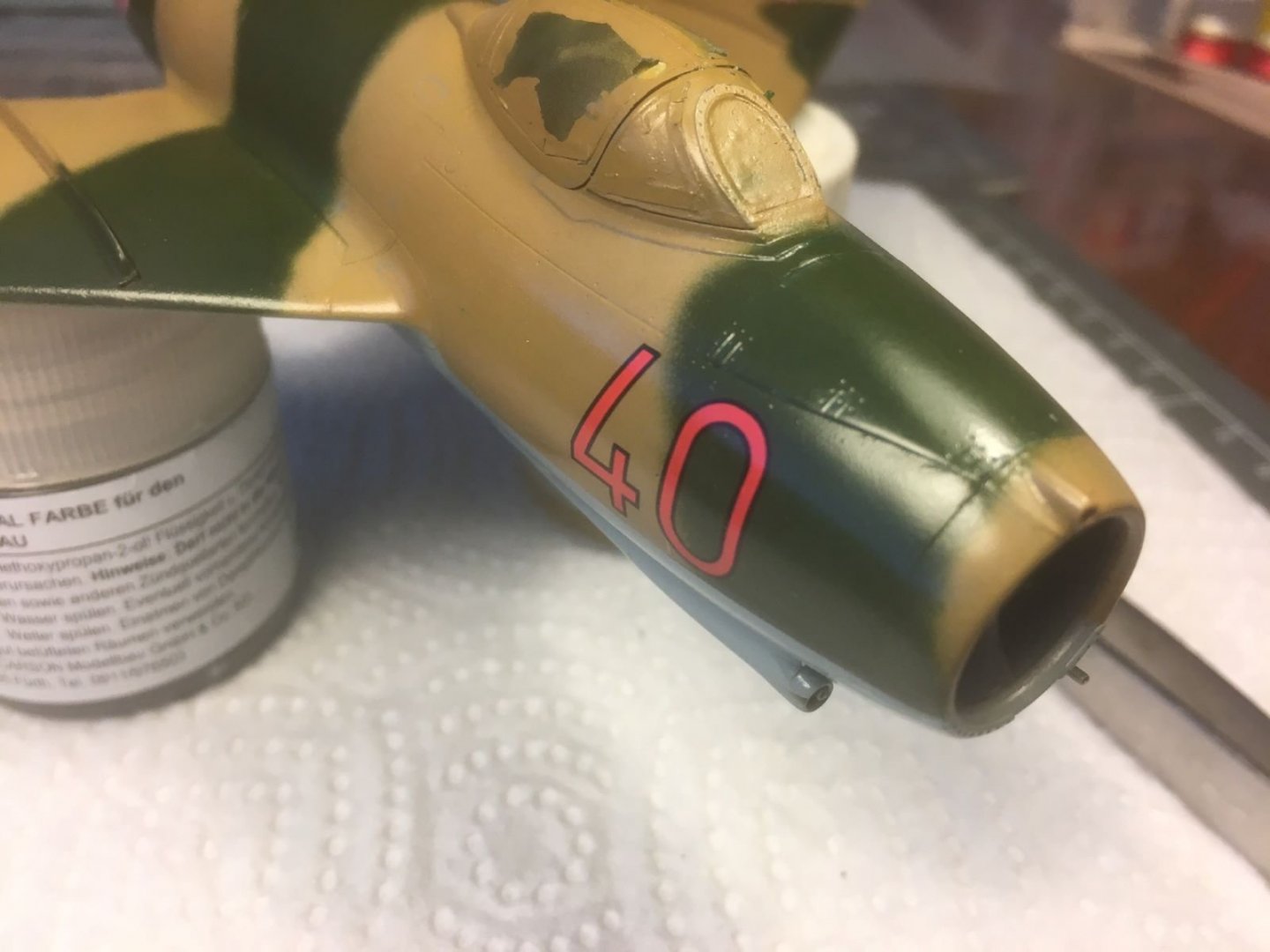
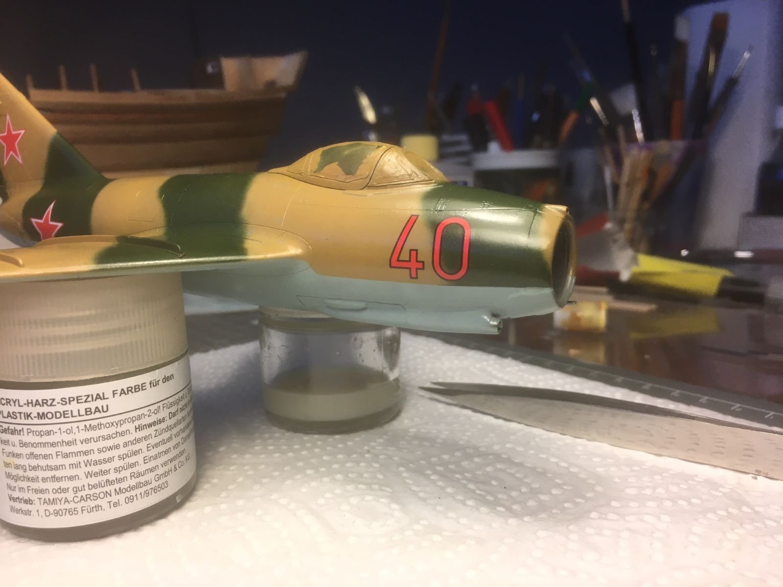
Thanks Mark for your comment. I hope you are right. However, I preferred a full, glowing red ... My fear is that the final flat coat will discolor the red stars even more. Let's wait and see.
-
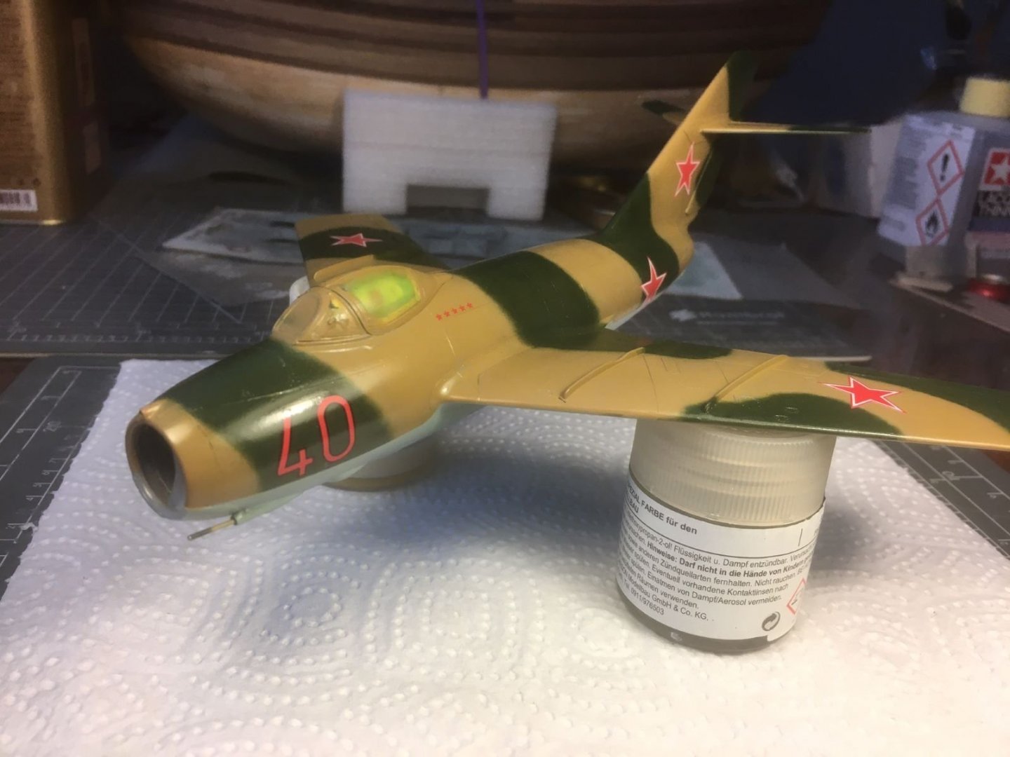
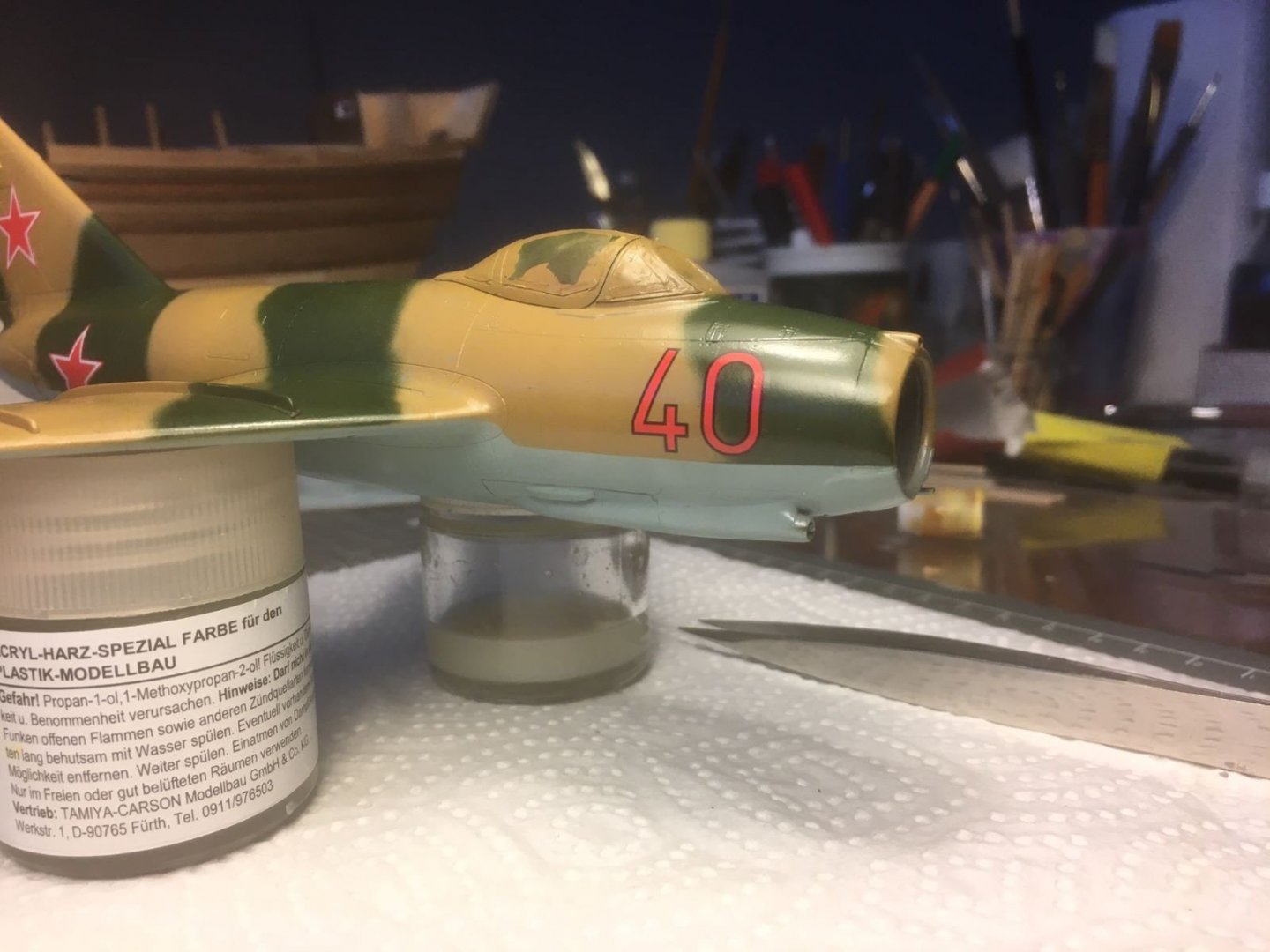
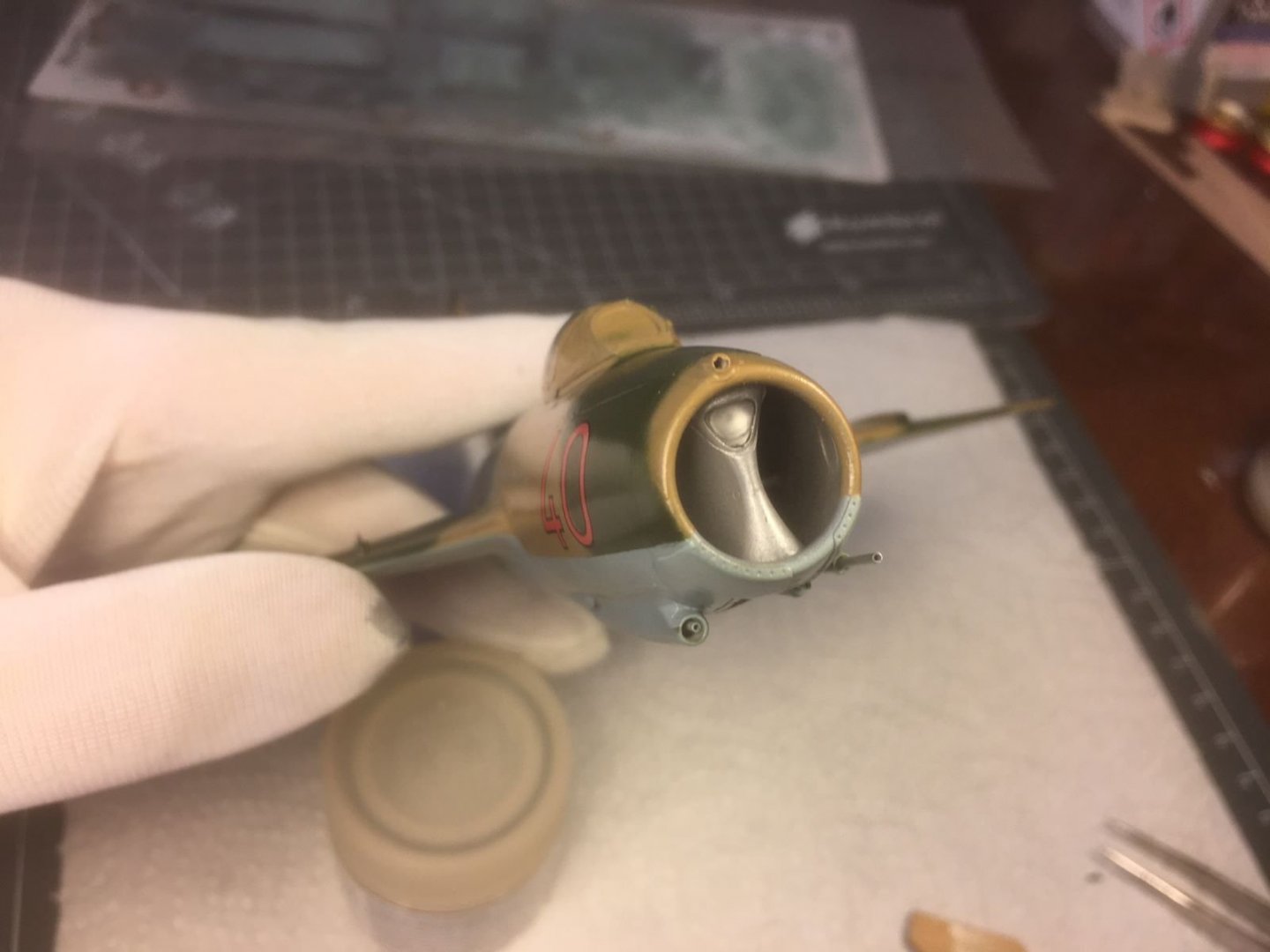
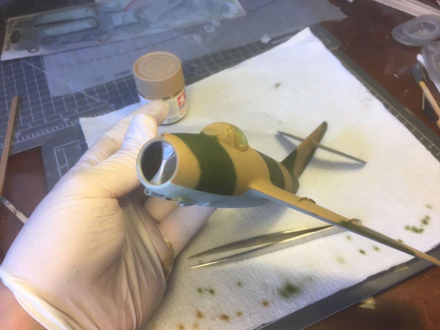
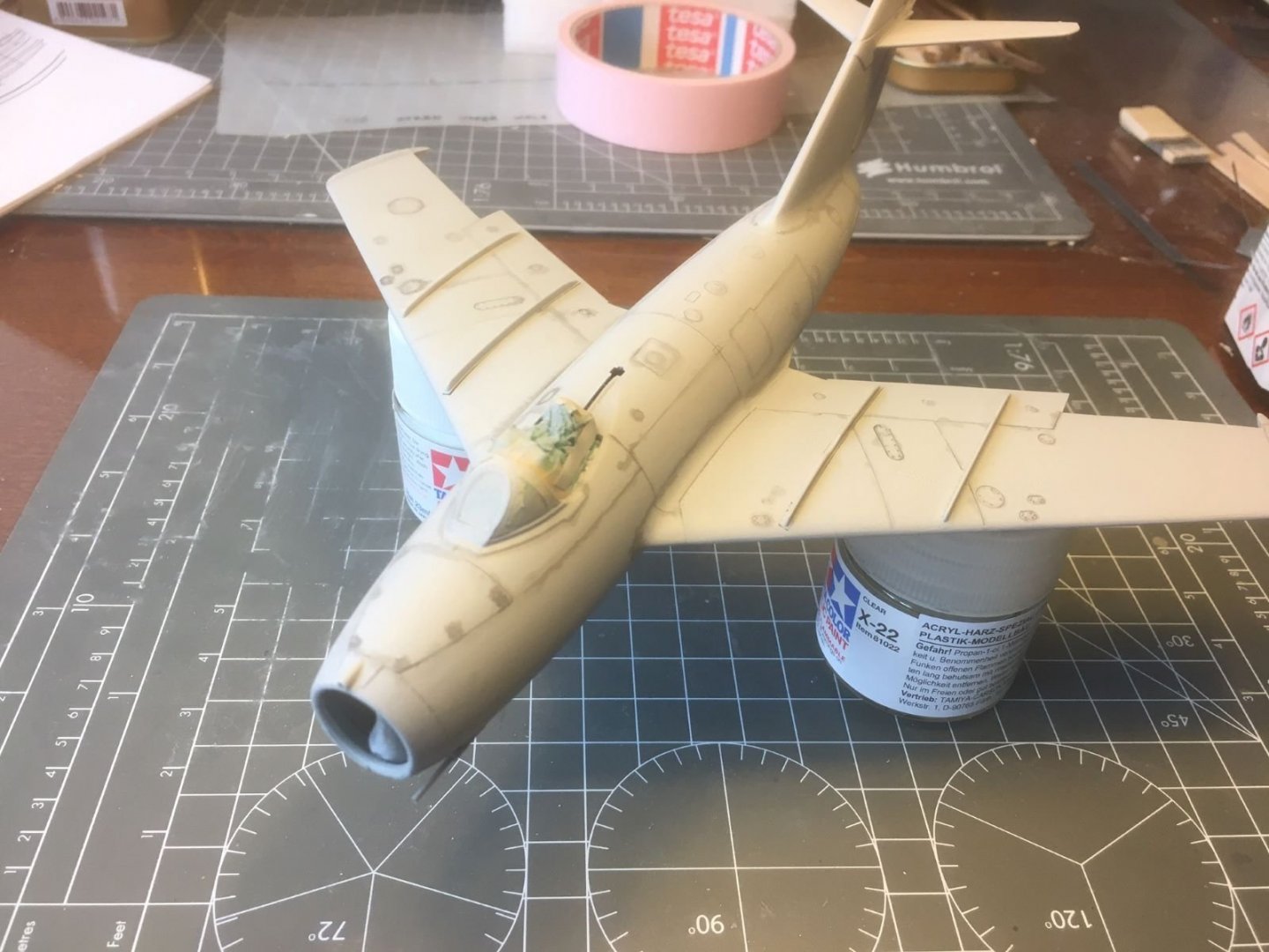
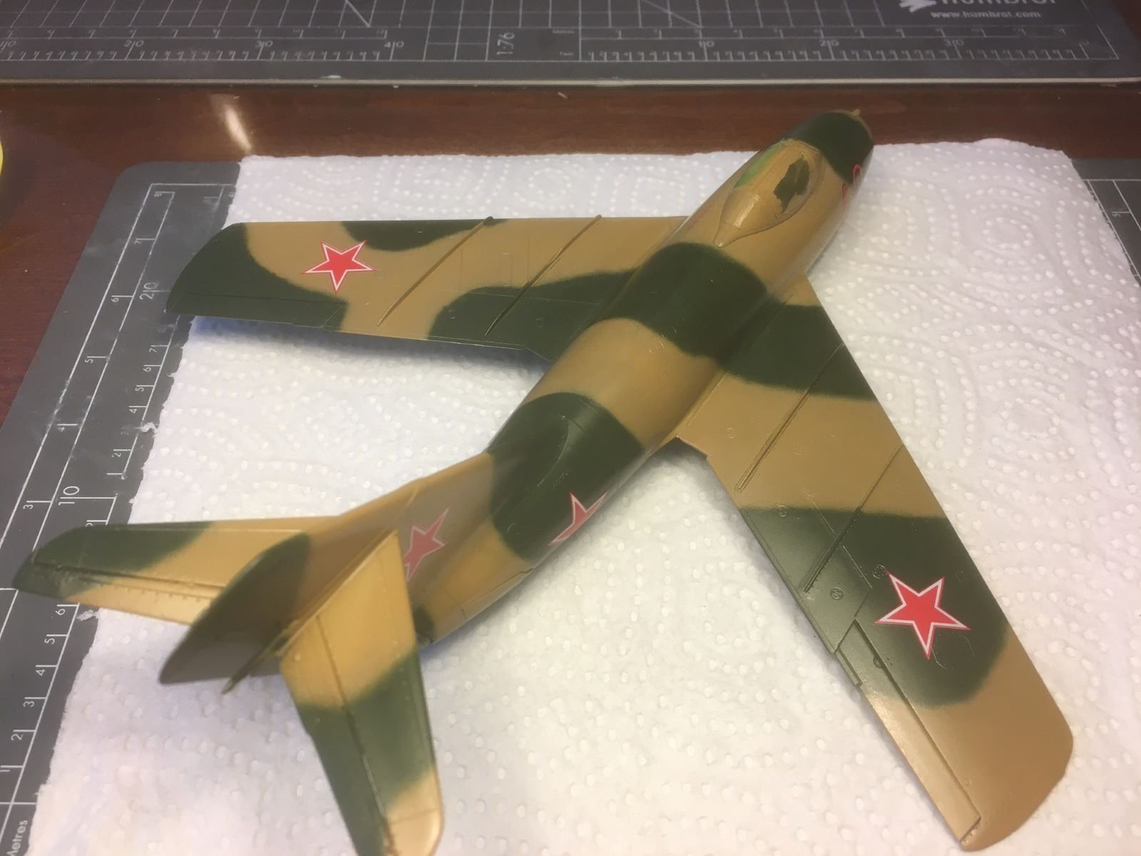
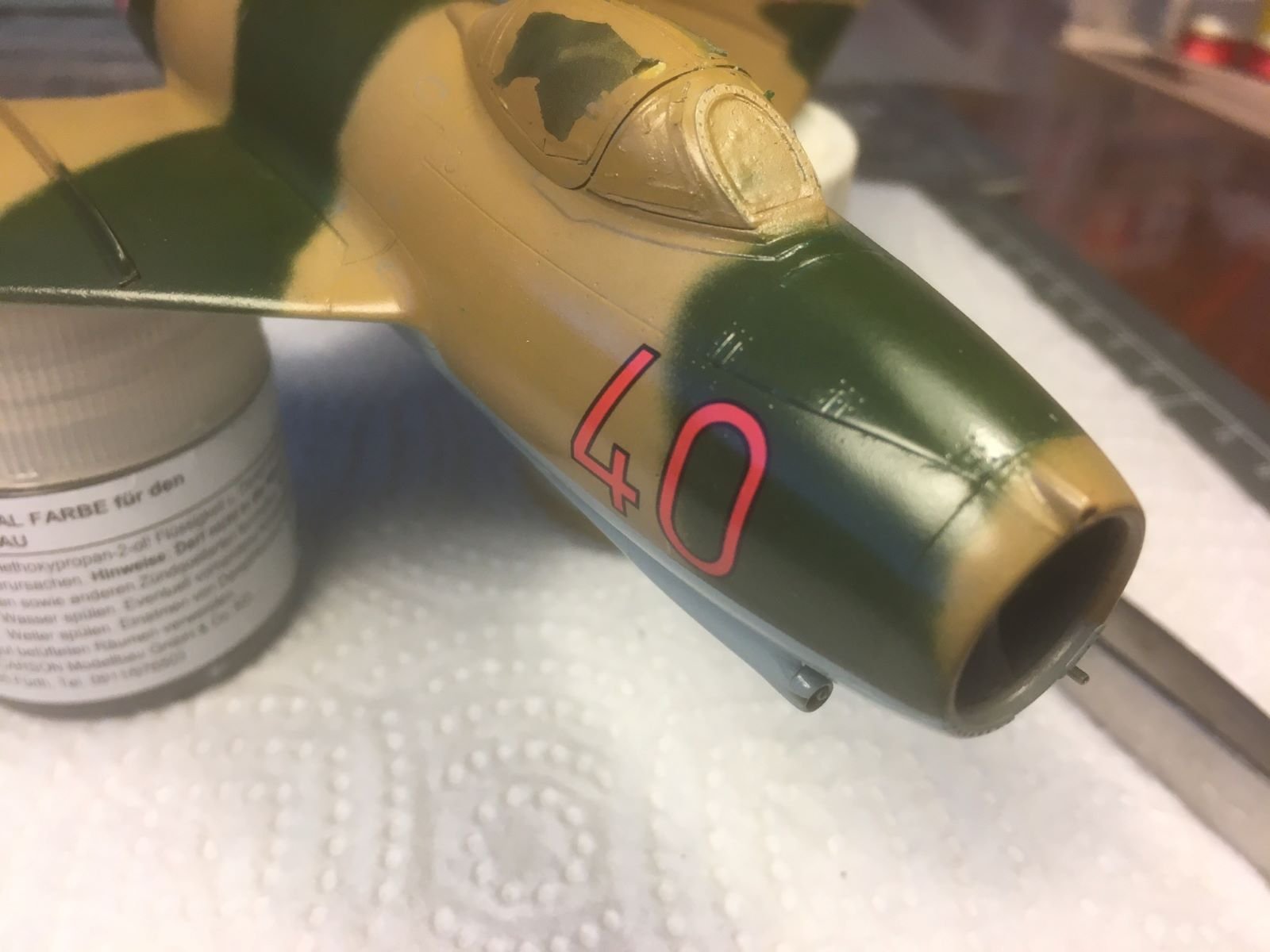
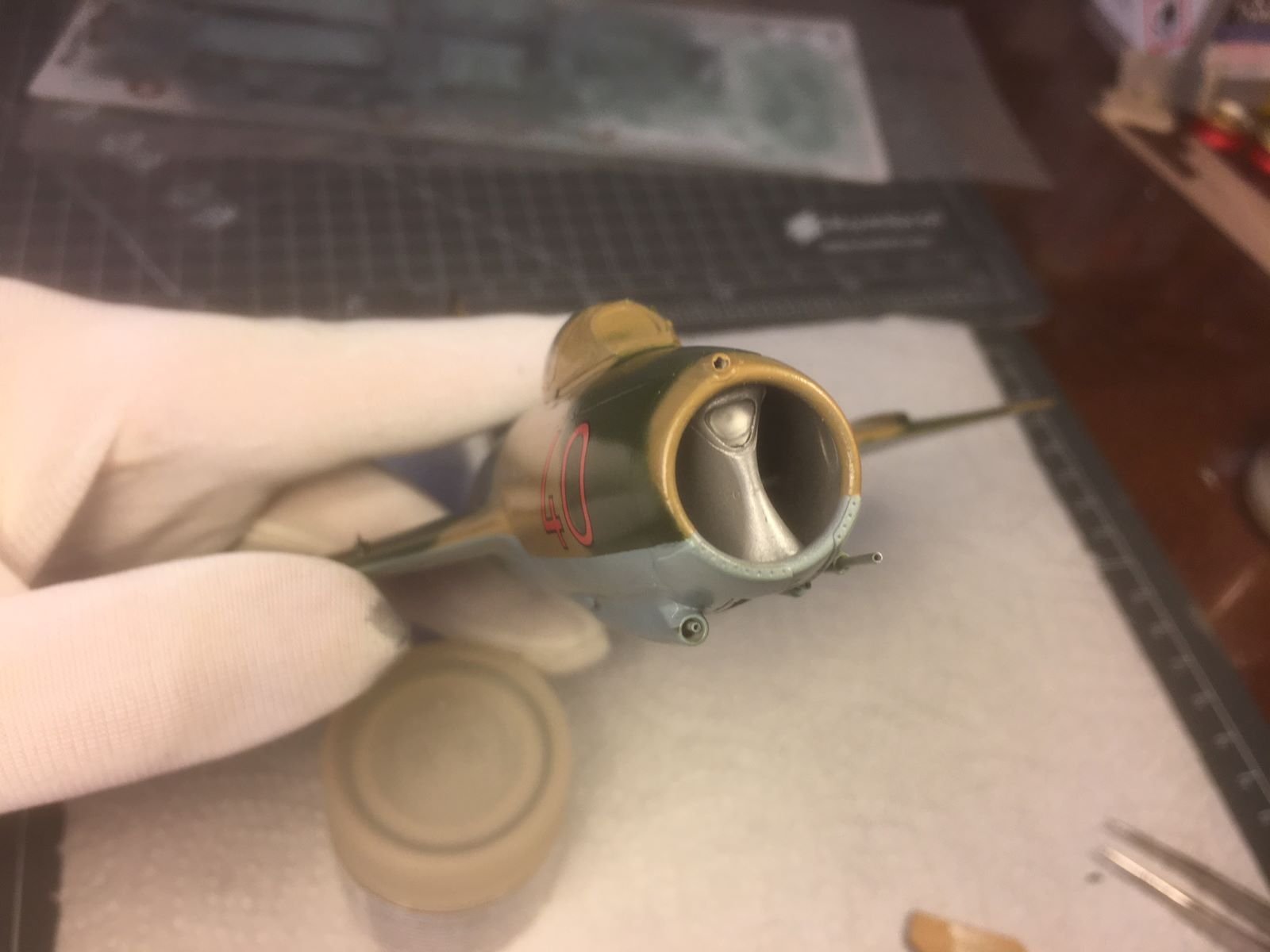
Dear all, went on with the finish of the camouflage and brushed on a layer of floor polish to obtain a smooth surface in preparation for the decals. The floor polish is very quick to be applied, can be brushed, it is very thin, self-leveling and compatible with the Tamiya paints. Actually I brushed two layers on the location of the decals. It was followed by a very light wet sanding which removed any remaining roughness. Then the decals were applied and a layer of Tamiya gloss X-22 sealed the paint and the decals. This version of MiG-15 is decorated with just few decals. The decals are sufficiently thin, with little carrier visible and conformed well to the surface. However, in my opinion, they have a shortcoming in the saturation of their colors. The red tone, which is the predominant one for this aircraft, does not look as a full saturated red, and appears slightly discolored, almost pinkish: I think this is a shame for an aircraft of the Soviet Red Star 🙃. Unfortunately, I will have to live with that. Now the gloss paint needs to cure well for a couple of days before I can start working with oil washes for highlighting panels and details. Meantime, I removed the first mask from the landing light in the sect of the air intake. Now, I will have also to start working on the remaining parts like the landing gears, the drop tanks, etc. This is all for now, thanks for following, best regards, Dan.


- 109 replies
-
- 12
-
-
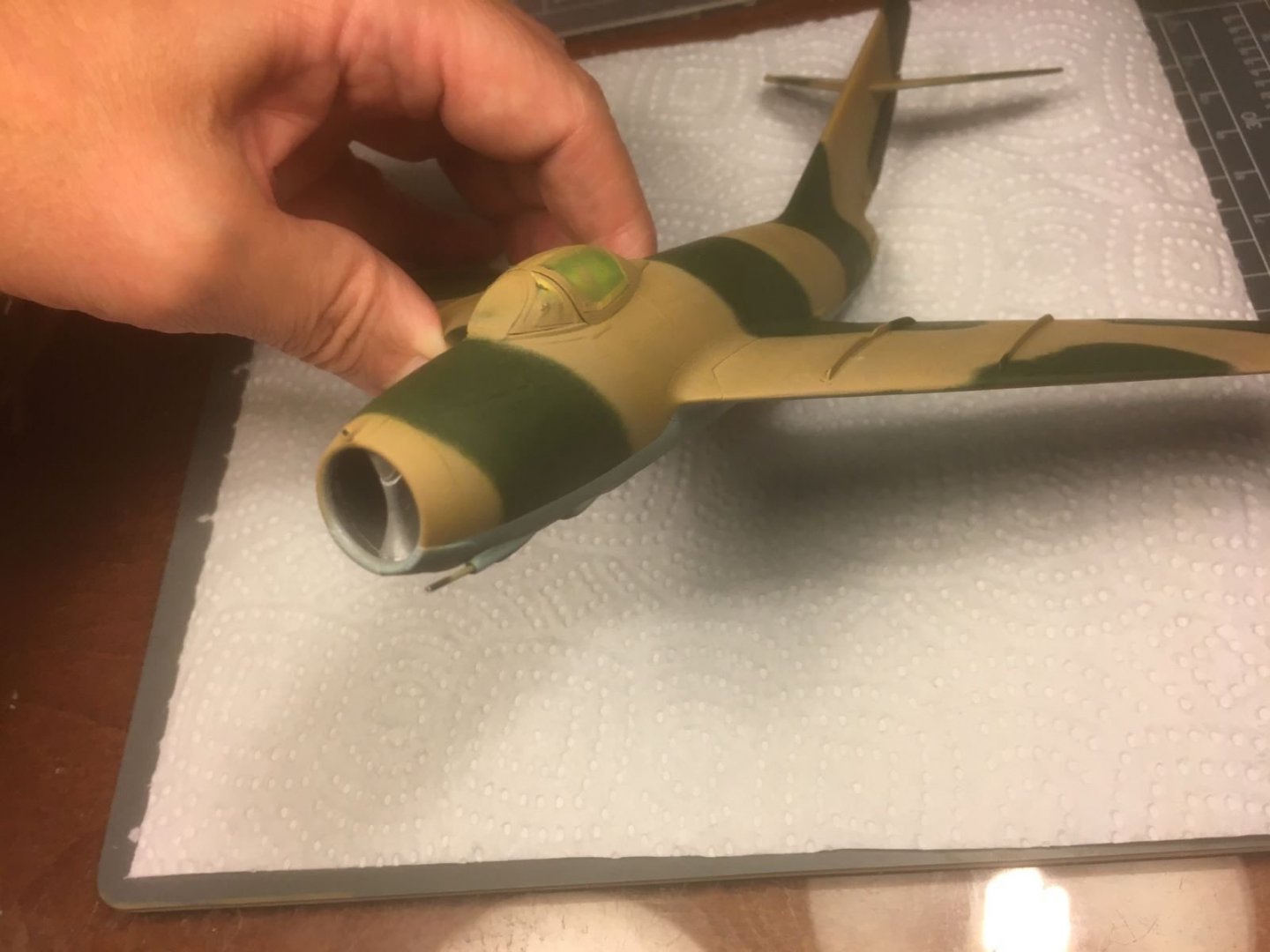
Hi all, little progress, I am just fixing paint defects. Eventually I modified the camo stripe which I did not like. Next, I will spray a coat of gloss clear paint. Best regards, Dan
- 109 replies
-
- 13
-
-
1/48 Italeri Hawk T.1A (On Hold)
Danstream replied to Old Collingwood's topic in Non-ship/categorised builds
Very nice work on the cockpit and other details. I built the Airfix kit years ago, but it was not as good as this one. Best regards, Dan. -
Hi, if you want to bring up the details of the cylinders, you might try to touch the fins with a fine brush loaded with Tamiya black liner. Capillarity should pull the ink into the slots between the fins. If you do not have that product at hand, you might try black aquarelle out of the tube diluted with water. Adding a drop of dish soap to the water, will break the surface tension of the water and the color will run better into the slots. Good progress with your big Corsair. Best regards, Dan.
- 136 replies
-
- 11
-
-
-
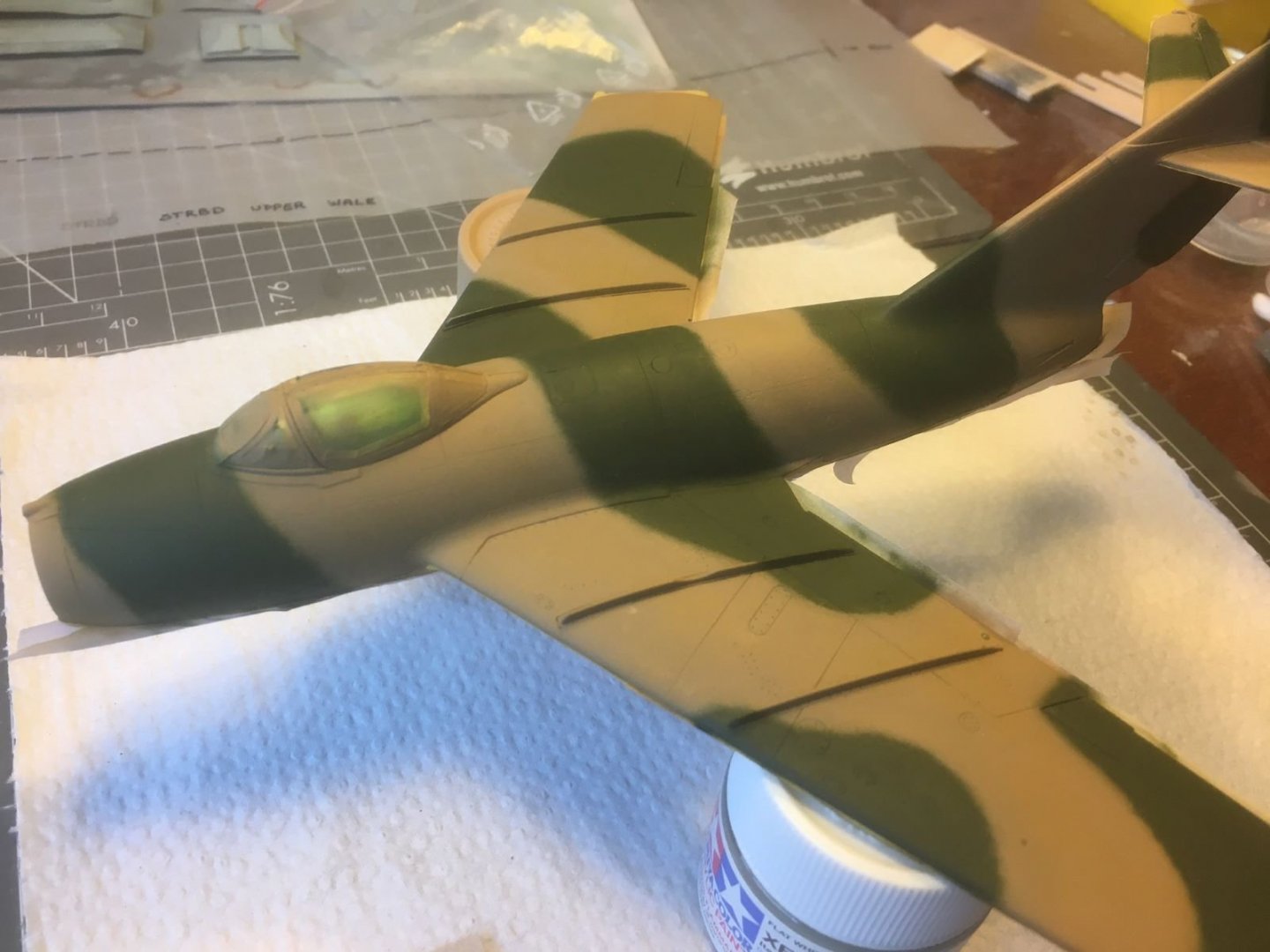
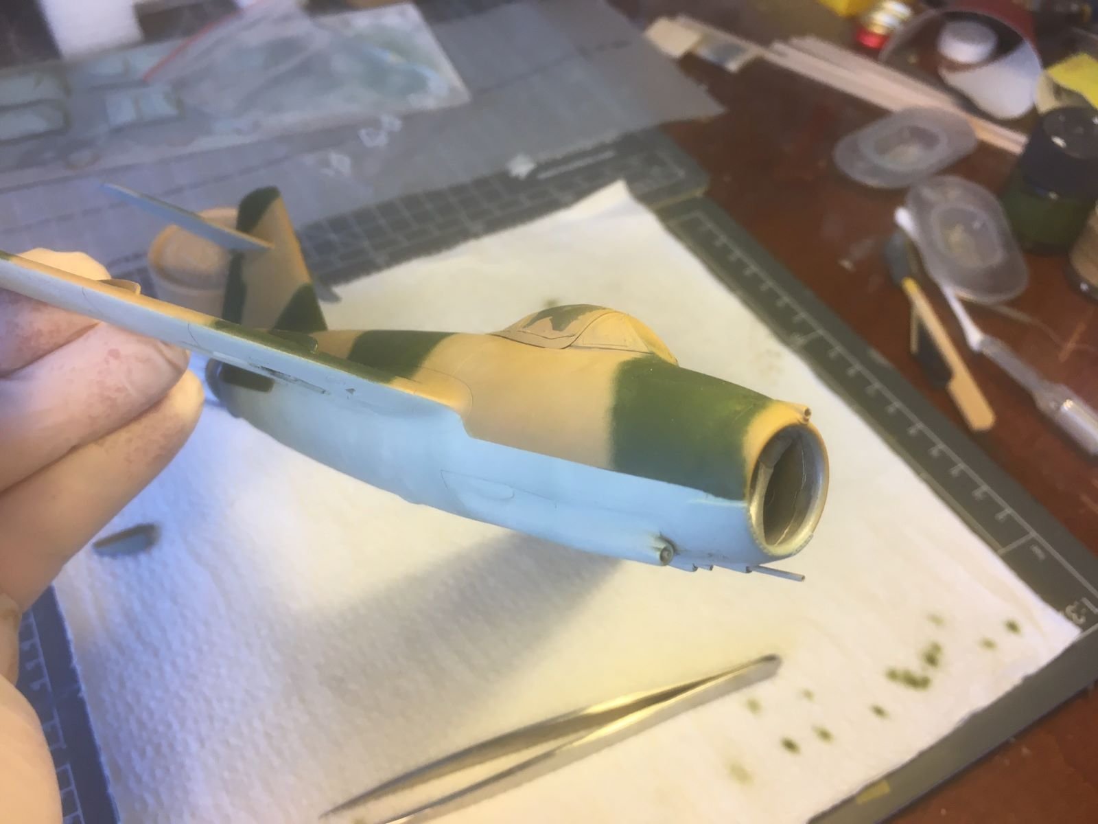
Hi Denis, really happy that you like my paintwork. It is not perfect though, the defects are little oversprays, points where the paint is not covering well, etc. However, above all, the thing that bother me most is the last brown stripe on the fuselage, just at the root of the fin which looks much narrower than the other ones. I am thinking of adjusting it, but there are some risks involved, you know the saying 'perfect is the enemy of good' ... I will let it sink for a while. Thank you and best regards, Dan.
-
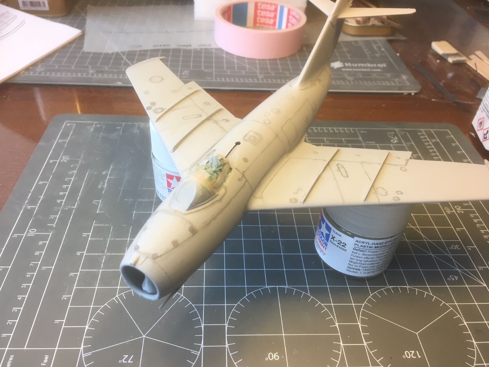
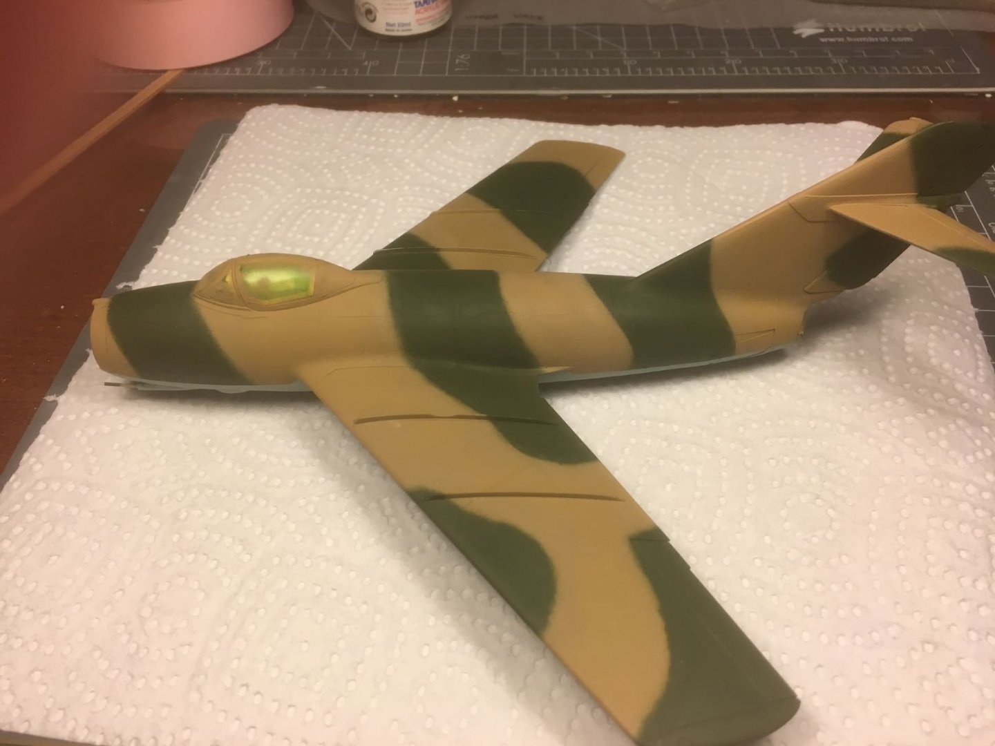
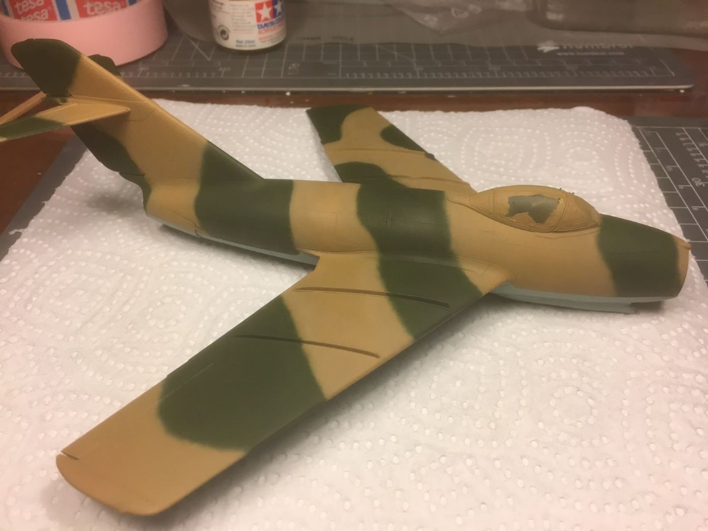
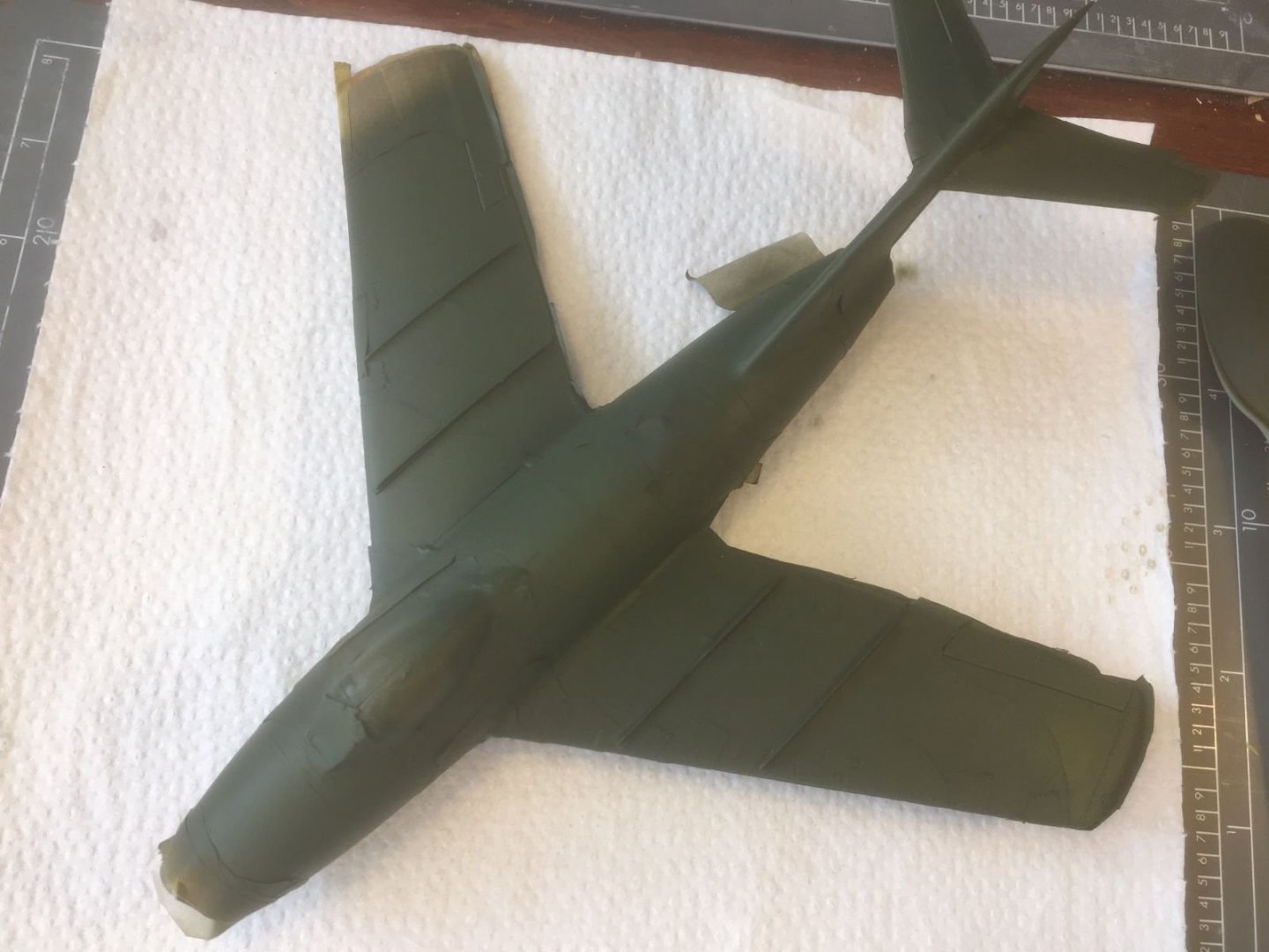
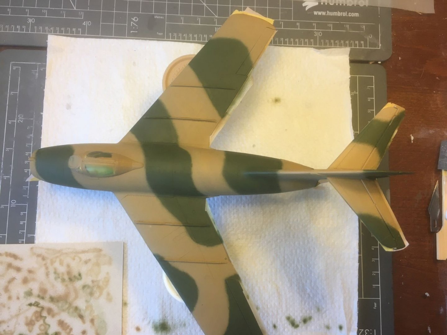
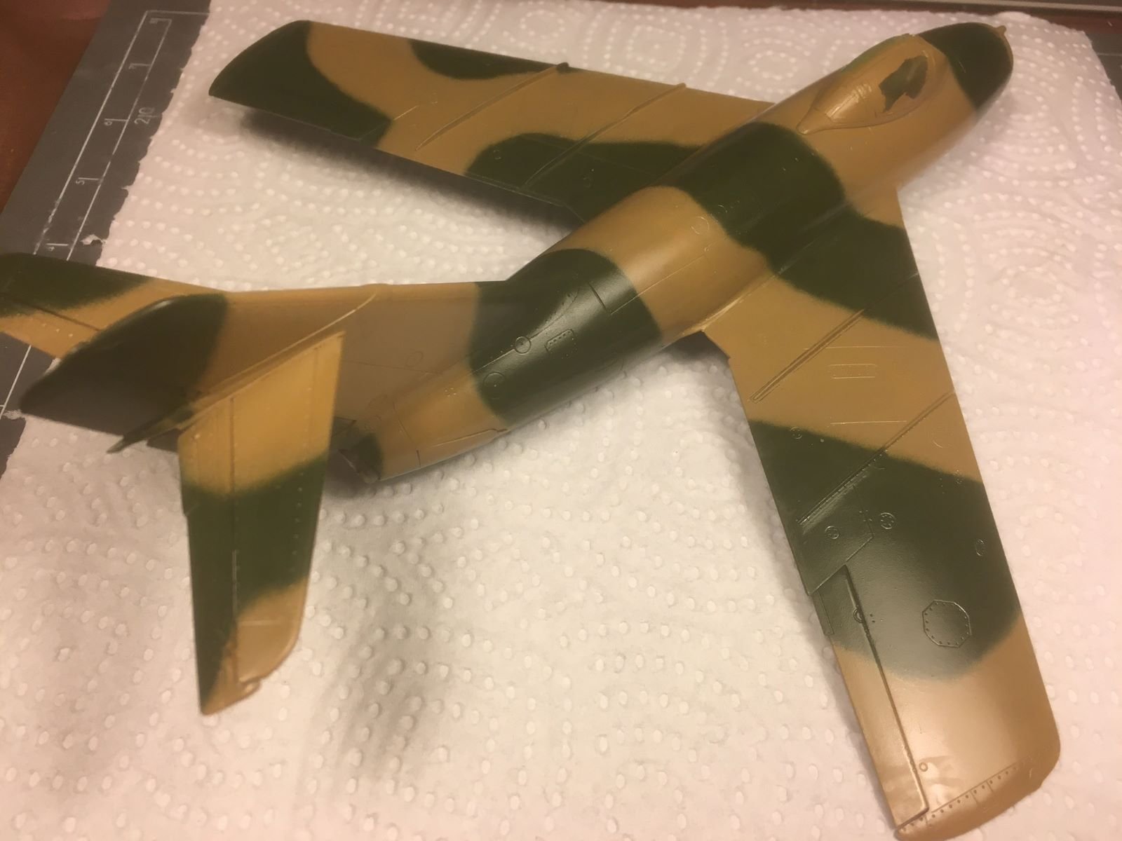
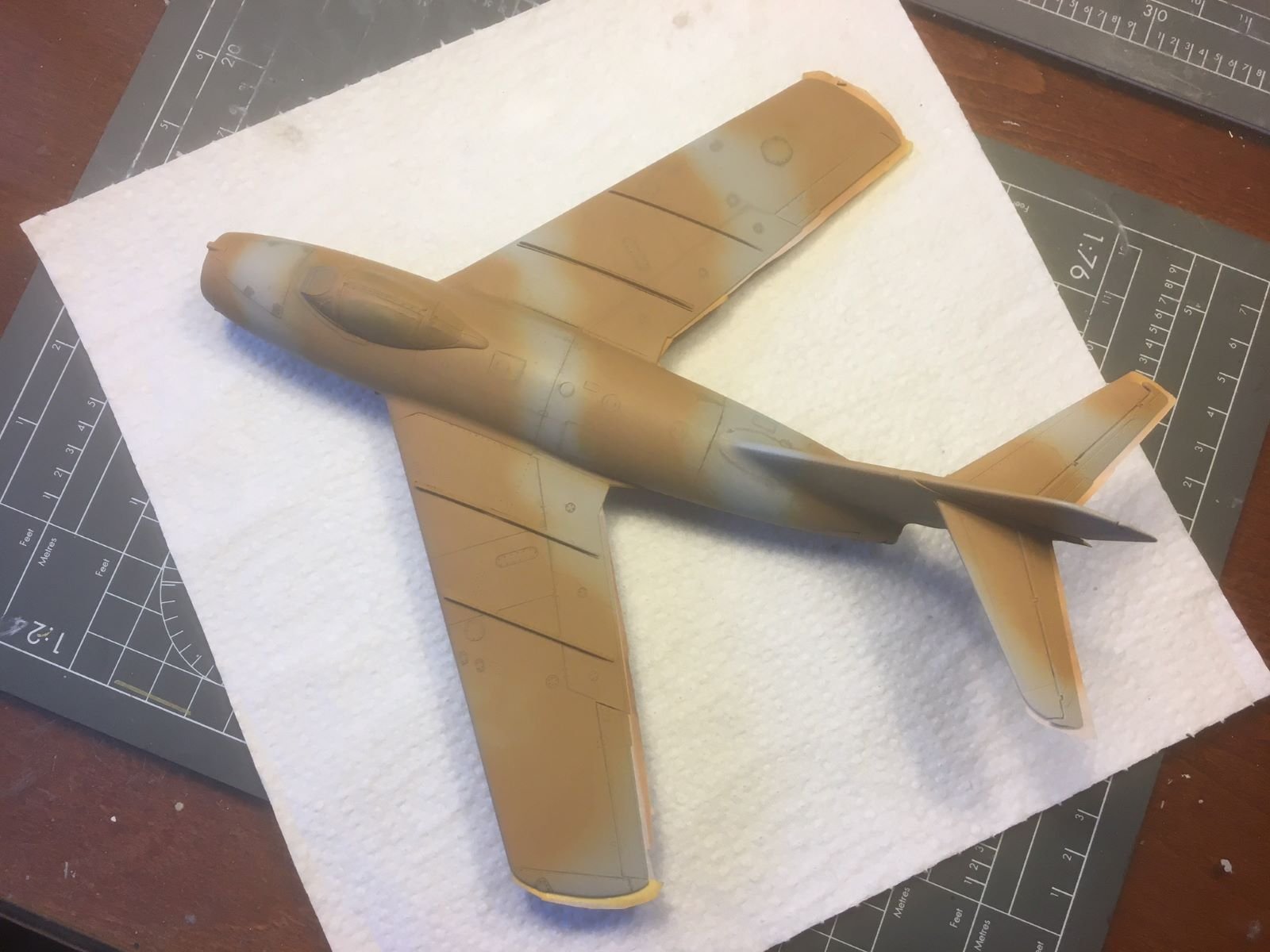
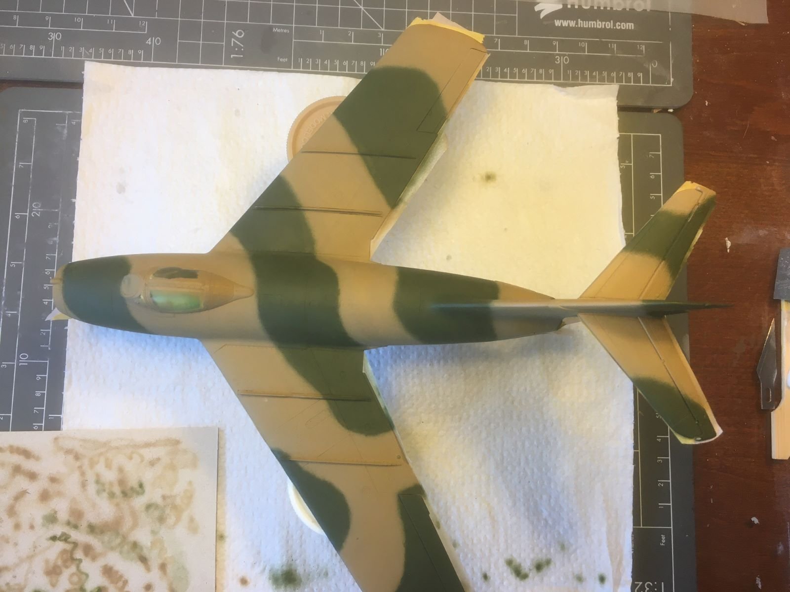
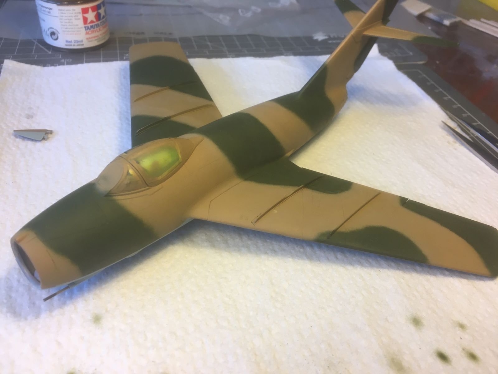
Hi all, after quite some time, I am able to post some progress on this build. I had to apply the camouflage with several iteration because I did not like the colors which I originally chose. I will post a little of the history, just to show why it took so long. The first picture shows the airframe ready to be painted. Surface was degreased, lower surface were masked and the camo pattern was outlined with a pencil. Then I applied the lighter color, the Tamiya XF-59 Desert Yellow: However, I did not like how this color came out, being it too pink, too similar to the one used during the gulf war. Nevertheless, I went on with the green, the XF-13, which was instead too similar to a NATO green. The result was not very Soviet-like, in my view. At the end, I took the bold decision of removing all that camouflage work. For the new light brown I started from a RAF Dark Earth which I lightened with white and yellow while for the green I made a 50-50 mix with the previous XF-13 and XF-5, which is a brighter green. This time, I tried to spray the camouflage bands freehand with my airbrush. The final result was declared OK after many touch-ups to correct the most obvious oversprays. Finally, the masking tapes were removed from the lower surfaces and the paint was wet sanded: Now, I will have only to address the few hundred defects and it will be ready for the glossy paint. Best regards, Dan.


- 109 replies
-
- 15
-
-
if I may suggest anything, having worked on several (European) space missions, the best reference for modelers are pictures of the real thing. Artistic renditions for public relations purposes are not always reliable because, as said above by @Canute and @Egilman, they are built on the basis of often outdated drawings/diagrams. Especially the external thermal blankets pattern can change configuration according to the last thermal-vacuum test results and the latest info might not be propagated in full in the pre-existent documentation. F.i., the Apollo LEM vehicles, are known to be all slightly externally different from each other. Looking for period pictures, you have to pick the latest ones, preferably those that depict the pre-launch preparation. Searching for "voyager spacecraft jpl images" will bring you several nice pictures of the integration of the spacecraft. I will be following your build with interest, best regards, Dan.
-
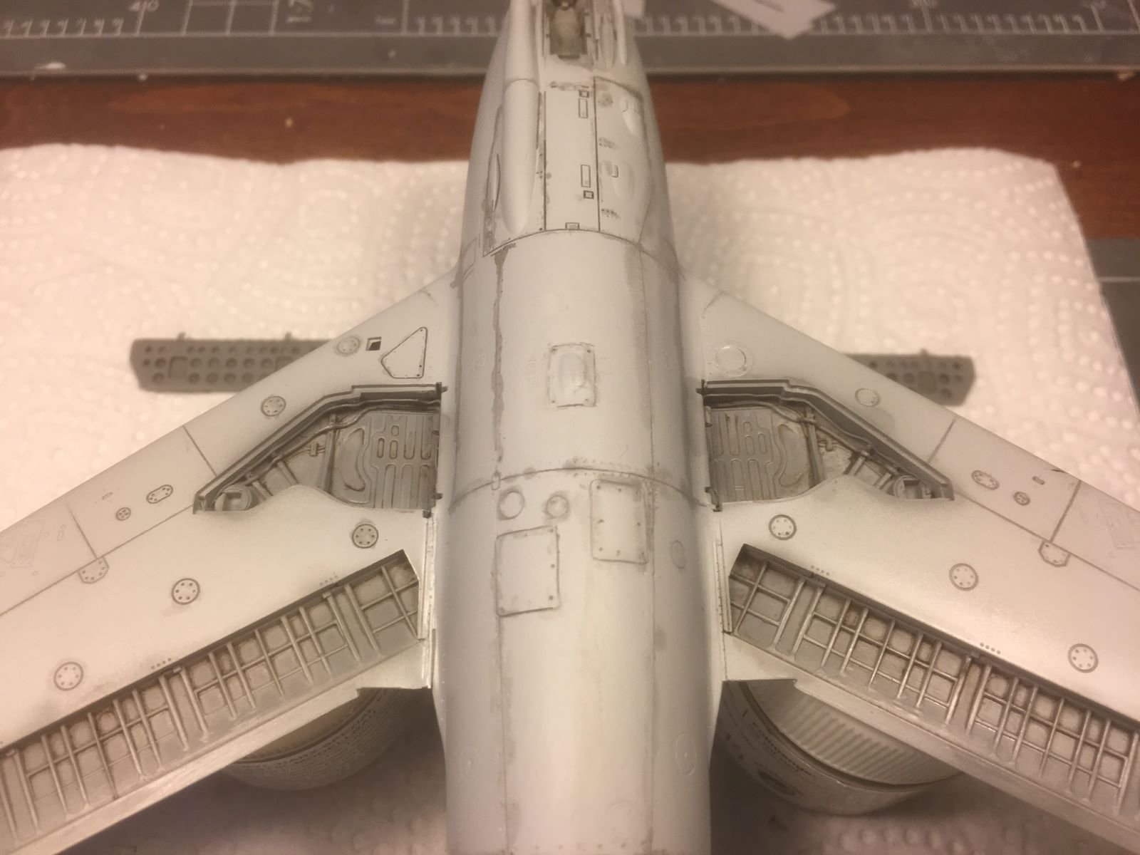
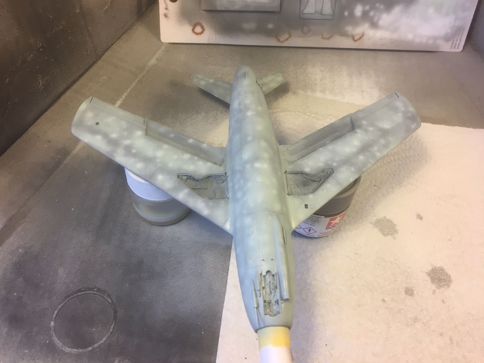
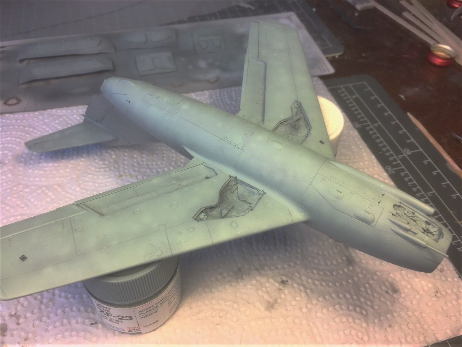
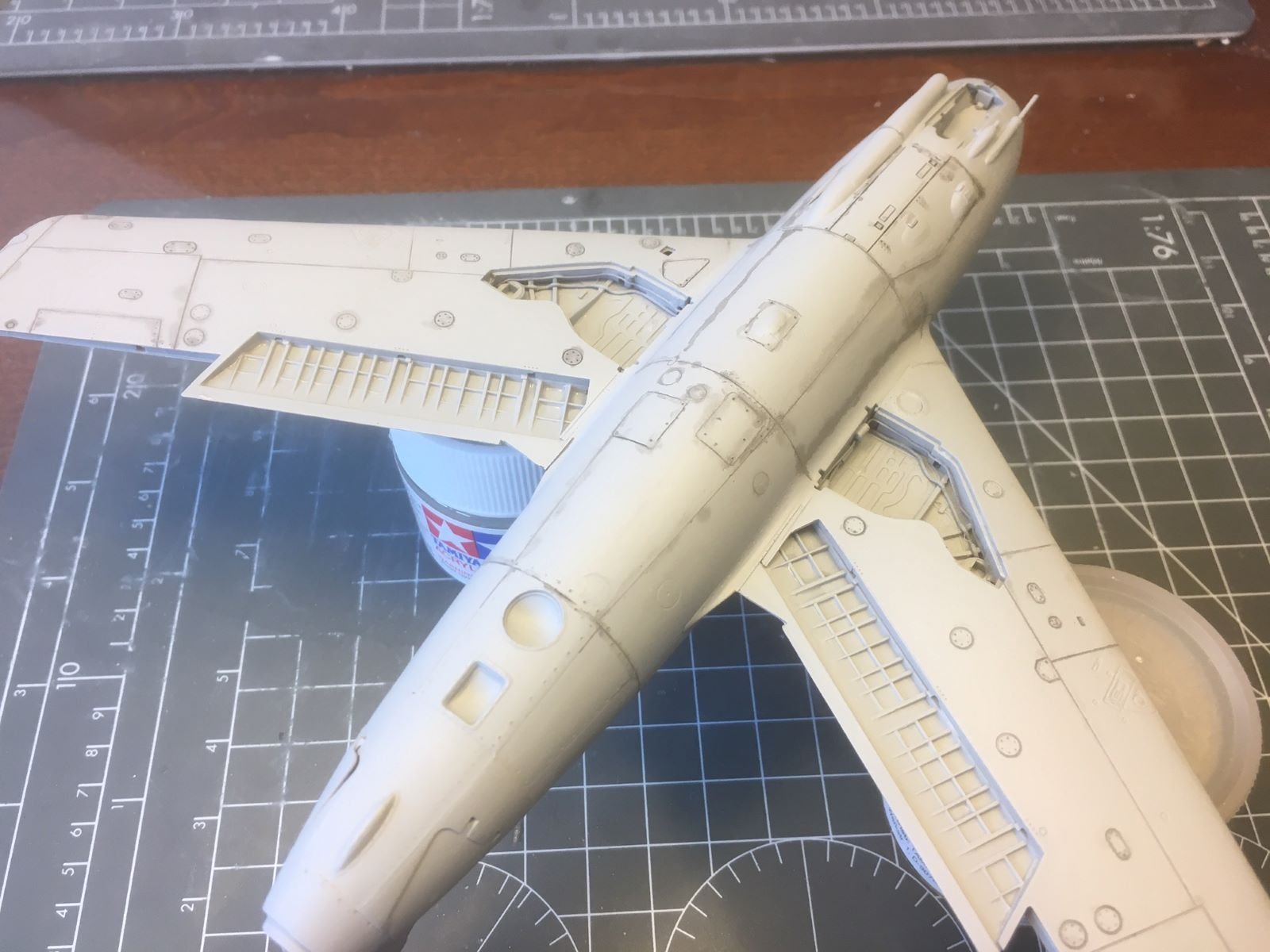
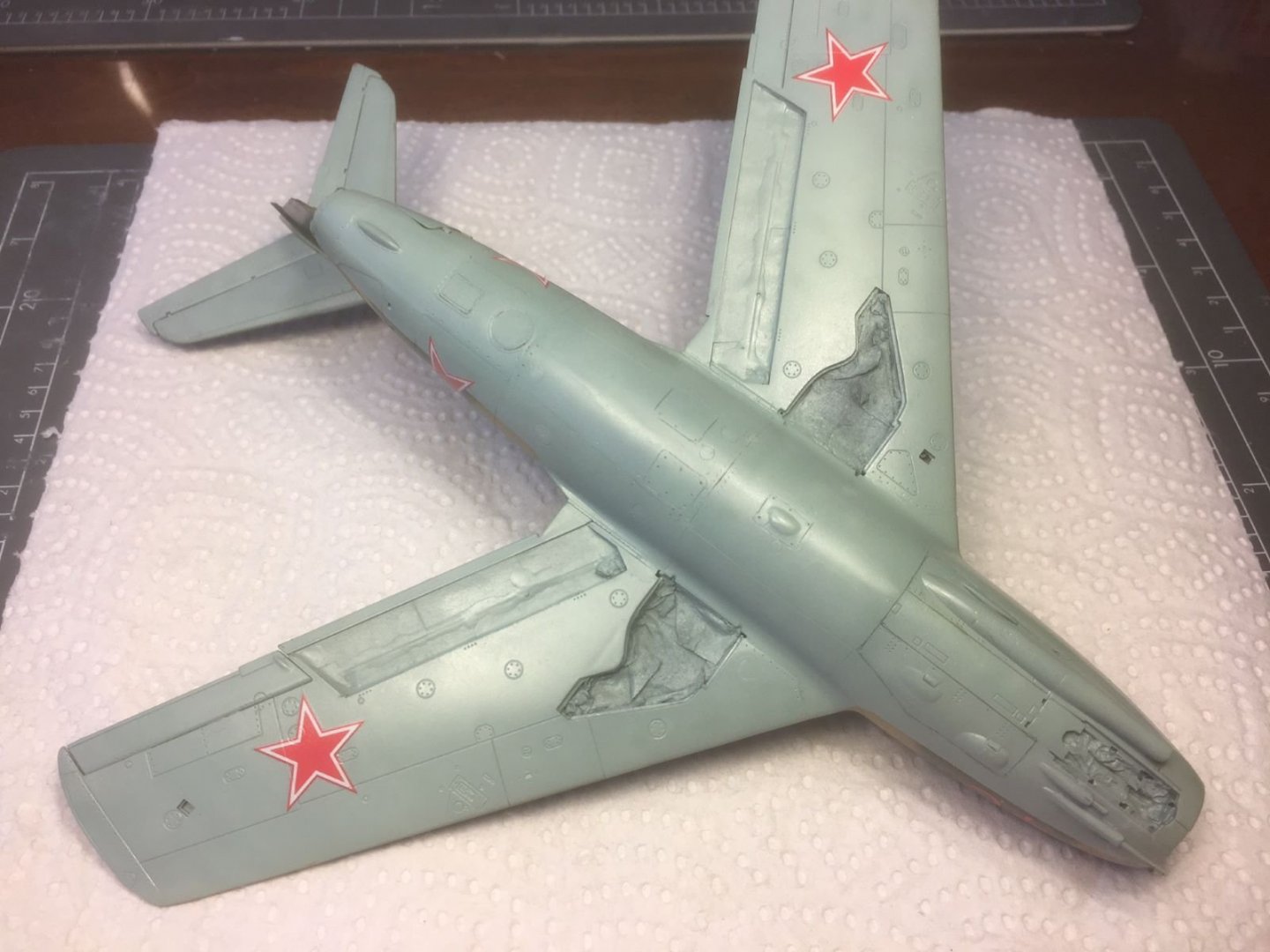
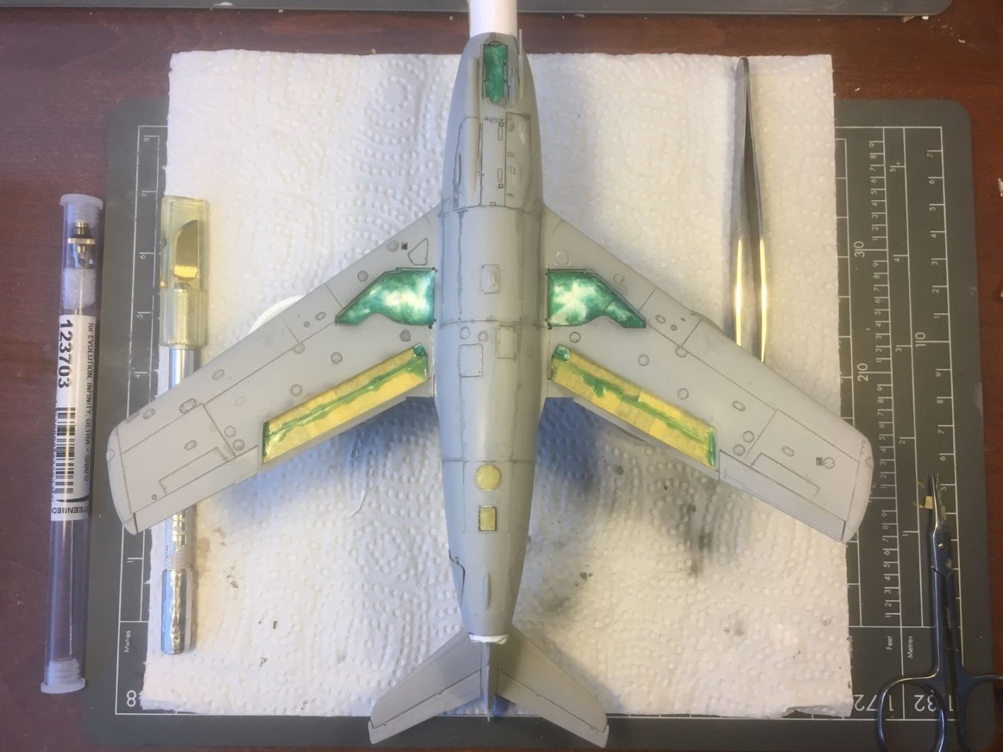
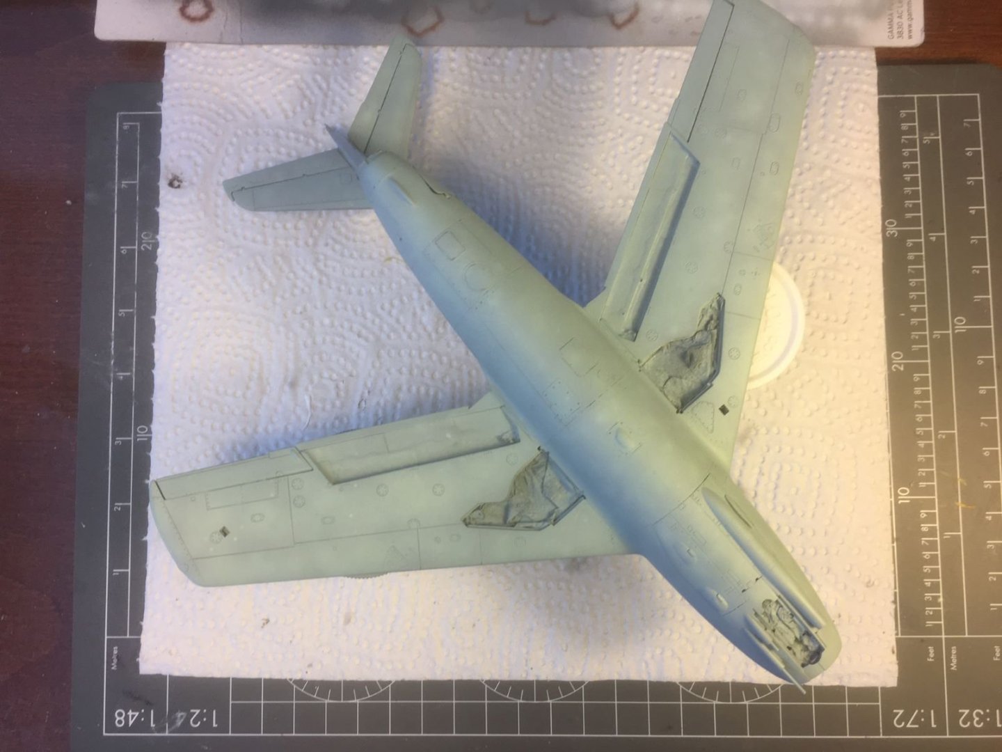
Dear all, I applied a grey color to the wheel wells and added some oil colors for reproducing some grime inside the wells. Then I masked all the bays and details that need not to be painted with the underside color: To render the light blue more interesting with some tonal variations, I started with an uniform dark color. I chose the Mr. Color Extra Dark Sea grey which sprays beautifully and dries with a slight shine. Then, I sprayed random blotches of matt white on top of the EDSG followed by wet sanding everything. Unfortunately, I forgot to take pictures of this step. After that, I started spraying thin layers of the light blue paint to gradually cover and uniformize the marbled surface. The light blue was obtained by a mix of Tamiya XF-23 (2/3) and flat white (1/3). This is a picture that I took after few layers. At the end, I obtained a slightly non-uniform coverage of the light blue. Later on, I will add a little post-shading with a darker tone of the blue. That is all for now, next I will tackle the upper surfaces. Best regards, Dan.
resiz.thumb.JPG.b2eb7fefbc0186aab1b573019a1b44ad.JPG)


- 109 replies
-
- 15
-
-
Very nice build. I like the shades you applied on the camouflage colors. Well done, Dan,
-
To illustrate my comment, please have look of this vase where a ship is depicted (Ulysses and the sirens): https://www.britishmuseum.org/collection/image/478976001 This vase is from the same date (c.a. 470-480 BC) of the claimed date of the model. Dan.
- 62 replies
-
- 2
-
-
- amati
- greek bireme
- (and 1 more)
-
@ObviousNewbie, I am following with interest your build, being in the past interested in greek history and Homer poetry. I know that this is an unsolicited advise and I waited a lot before writing it. Please do not consider it if you think it is not worthwile. It is about the eye that you are going to paint/apply on the bow of your ship. It seems that you are going to place the eye with an inclination and with a 'cartoonish' style so to render a kind of 'angry' or 'menaceus' look. I do not think that this should be the case. Please look at documents of the time, like the mosaic above or the numerous pieces of pottery that can be found on the web and you will find that the eye is generally represented with a 'hieratic' look, without any particular expression. The eye was not meant to convey fear to enemies, like a nose art of an airplane, but rather to protect the ship, to give to the ship the sense of sight that would help to navigate and follow safely the proper routes. Best regards, Dan
- 62 replies
-
- 5
-
-
- amati
- greek bireme
- (and 1 more)
-
Dear all, first of all, many thanks for all the help and suggestions that you forwarded to me. At this point, I owe you some clarifications, though. The kit provides decals for a Chinese aircraft with a metallic finish and for a Soviet one sporting a camouflage used during the Korean war. Not being interested in Chinese markings, I rather prefer to finish the model with Soviet markings, hence with a camo livery. Admittedly, a metallic finish might well be more iconic for this plane, however, I would like not to outsource new decals for the soviet markings. The provided decals are suitable for the scheme portrayed in the picture of the RC model posted above by @popeye the sailor. This is a two tones camouflage (sand-brown and green) with light blue for the under surface. The colors to be used are subject of hot discussions which can be found on the web and which I will summarize below. My complain about lack of period pictures was not related to the choice of a camouflage scheme, rather to the fact that I usually try to get ideas for the weathering from these pictures. Not having pictures to refer to, I will have to figure out a plausible weathering by myself. Sorry for the confusion that my post I might have generated. @Egilman, indeed, the model reproduces a Mig 15 'bis', which was an improved version introduced after the first appearance of this jet. Coming back to the Soviet camouflage, probably, the unavailability of period pictures is due to the fact that the Soviet intervention in the Korean war had not to be advertised and kept as far as possible secret. Hence few pictures were circulated. It is reported that Soviets did not have standardized tints and the aircraft were painted with colors obtained by mixing basic tints like yellow, red, brown, etc. Therefore, color definitions are indicative only and the exact tints are everyone's calls. If you are really interested on this topic, I suggest you the following articulated and very informative discussion led by a Russian guy, author of a book on the subject, contained in the following link: https://www.britmodeller.com/forums/index.php?/topic/234949599-mig-15-korean-war-camo-colours/ As far as the colors that I will use, my choice is with Tamiya acrylic paints and are: - XF-59 Desert Yellow - XF-13 J.A. Green, which is a rather 'simple' green - XF-23 Light Blue, which I will fade with some white. Again, thank you for your interest and help, kind regards, Dan.
-
Thanks Denis, Glad that you find it nice. I must say that the most enjoyable part is starting now. I did not find period pictures of this aircraft wearing a camouflage, hence I will have to improvise the weathering and keep it on a low profile. Warmest greetings, Dan.
-
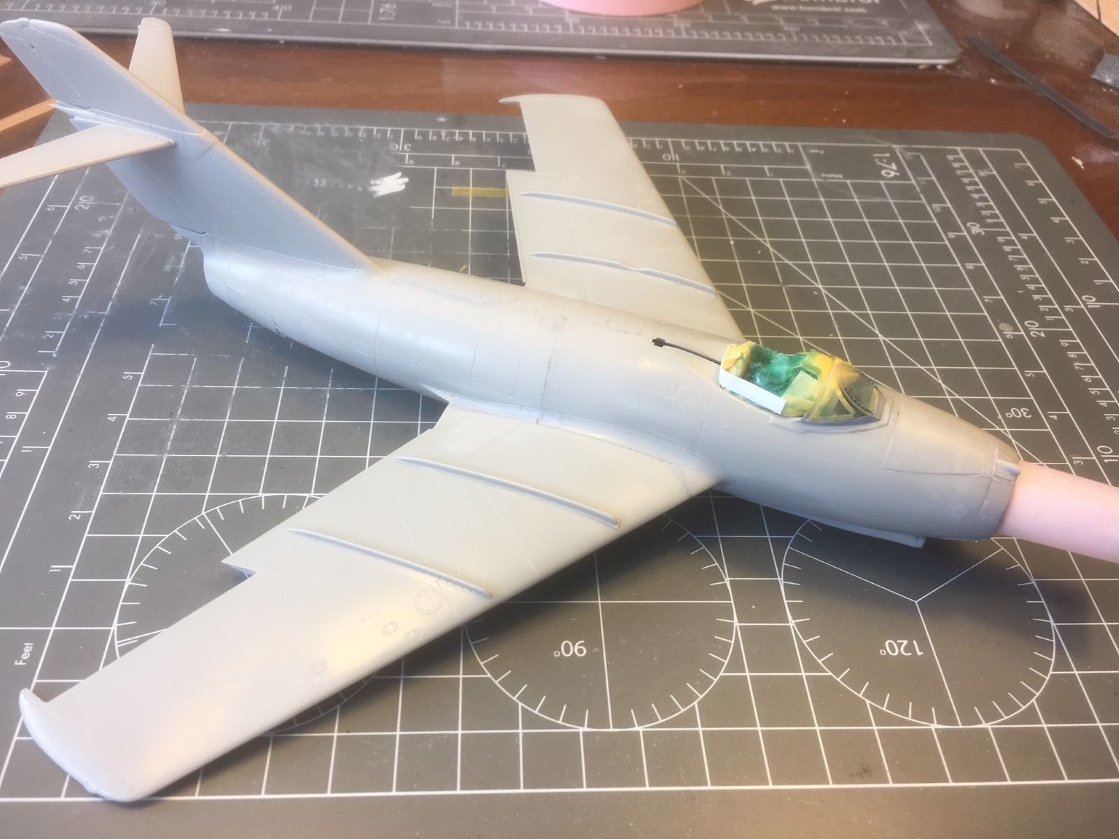
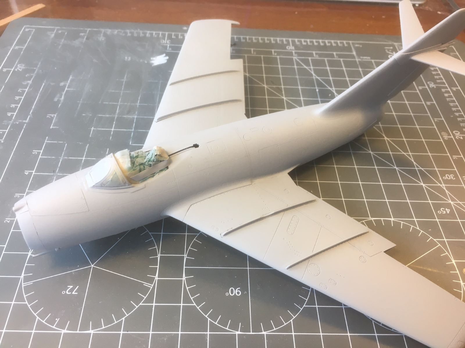
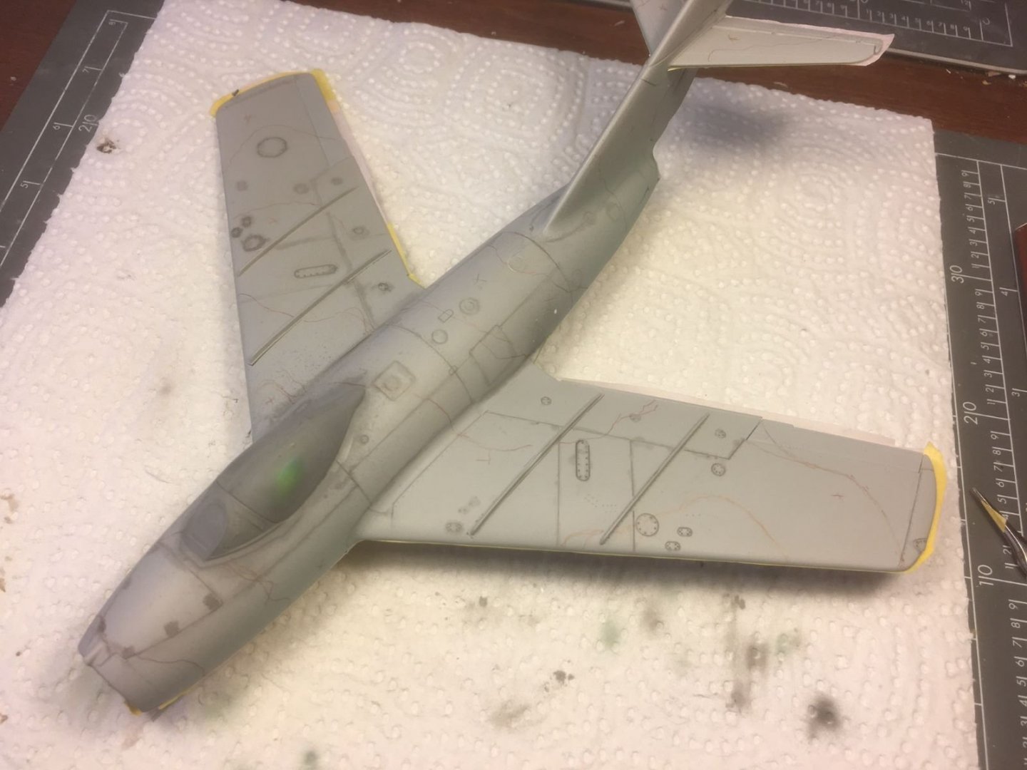
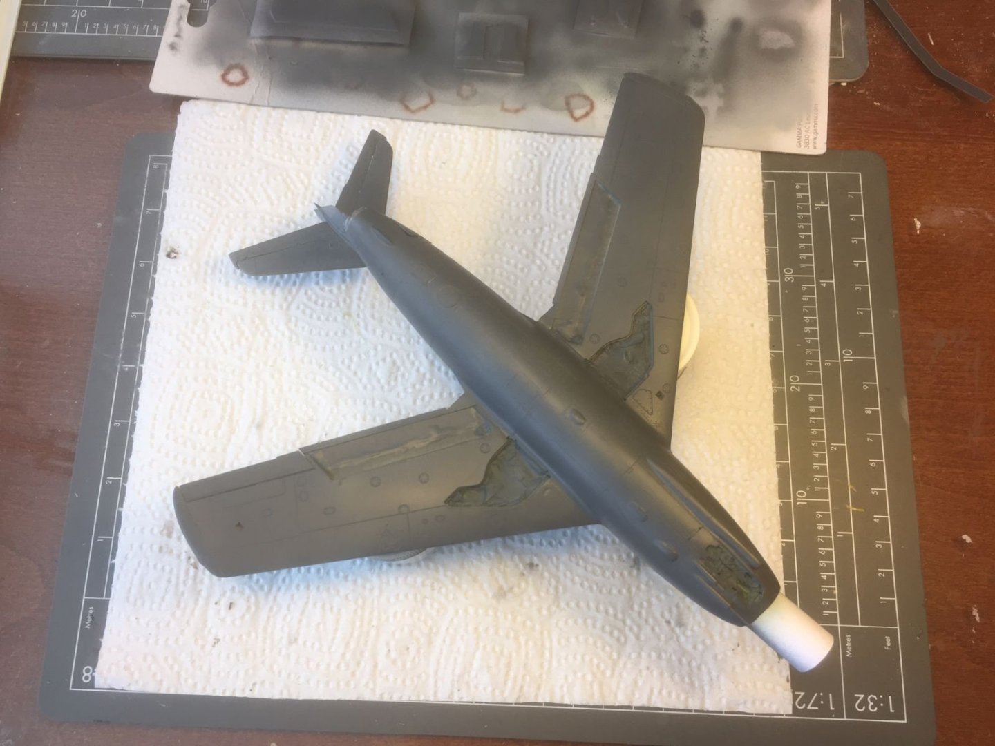
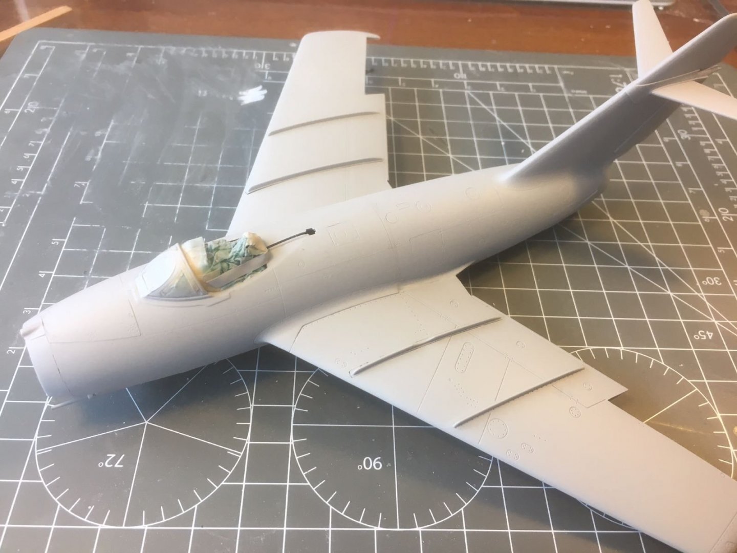
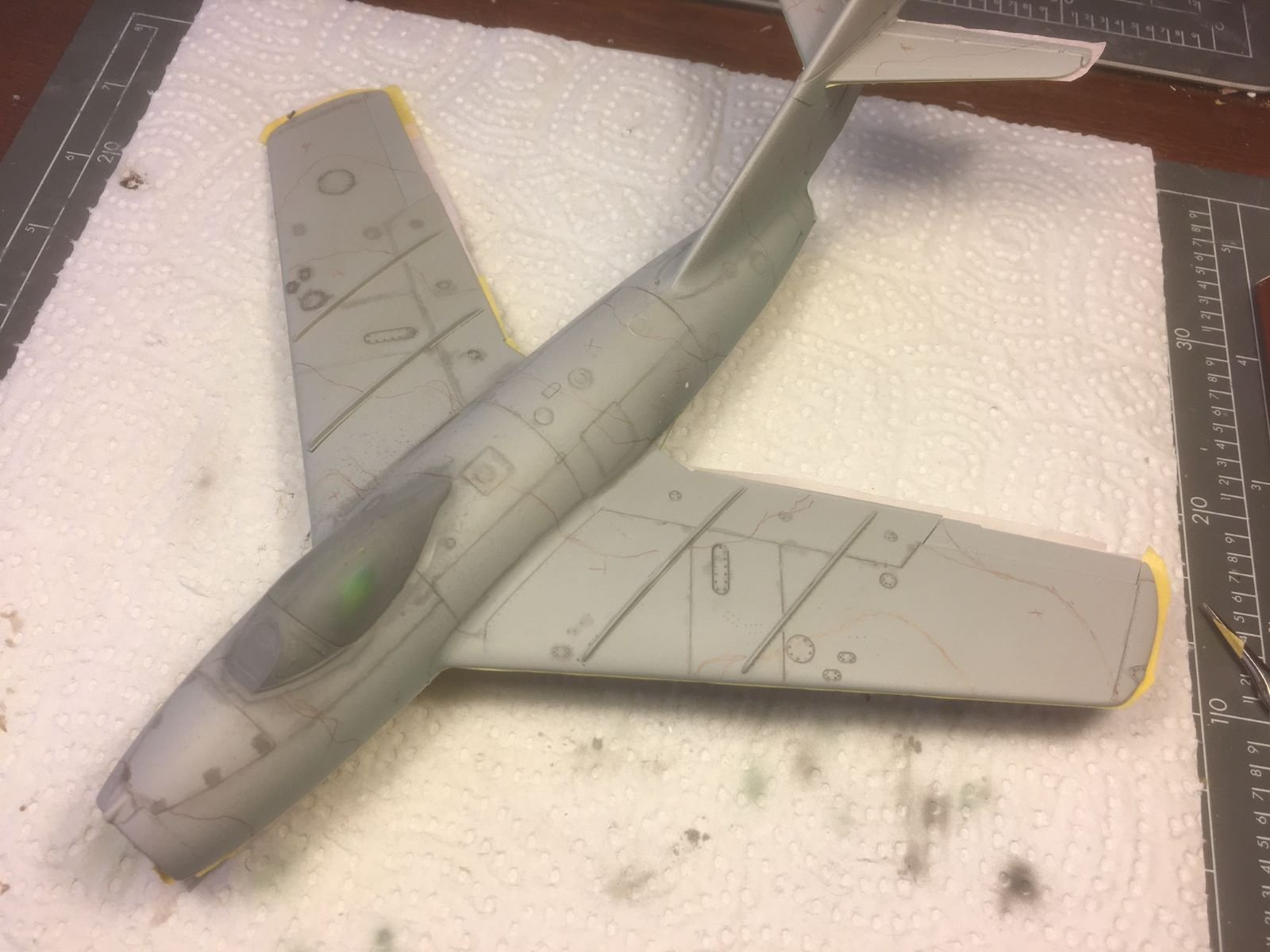
Hi all, after quite some time, during which I worked on my ship model, I am now back to my Mig. I glued all the main parts of the airframe, included the fuselage portions, and spent time on inscribing the lost details. In particular, the joint between the fuselage parts needed few CA filling, sanding and scribing sessions. Then the details which need to be left unpainted were masked, the airframe was readied for the primer by degreasing it with alcohol. I sprayed a coat of Mr. Surfacer 1500 which went on nicely leaving a very smooth surface. To check the work on the re-scribed details, I applied some Tamiya black panel liner which revealed the lines and gave a more 3D appearance to the model. After few corrections, I sanded all the airframe with wet extra fine sand paper obtaining a very consistently smooth surface. Now the model starts to look like an aircraft. Few bits to add, the control surfaces, flaps and landing gear covers need also to be primed and camouflage painting can start. Best regards, Dan.


- 109 replies
-
- 16
-
-

-
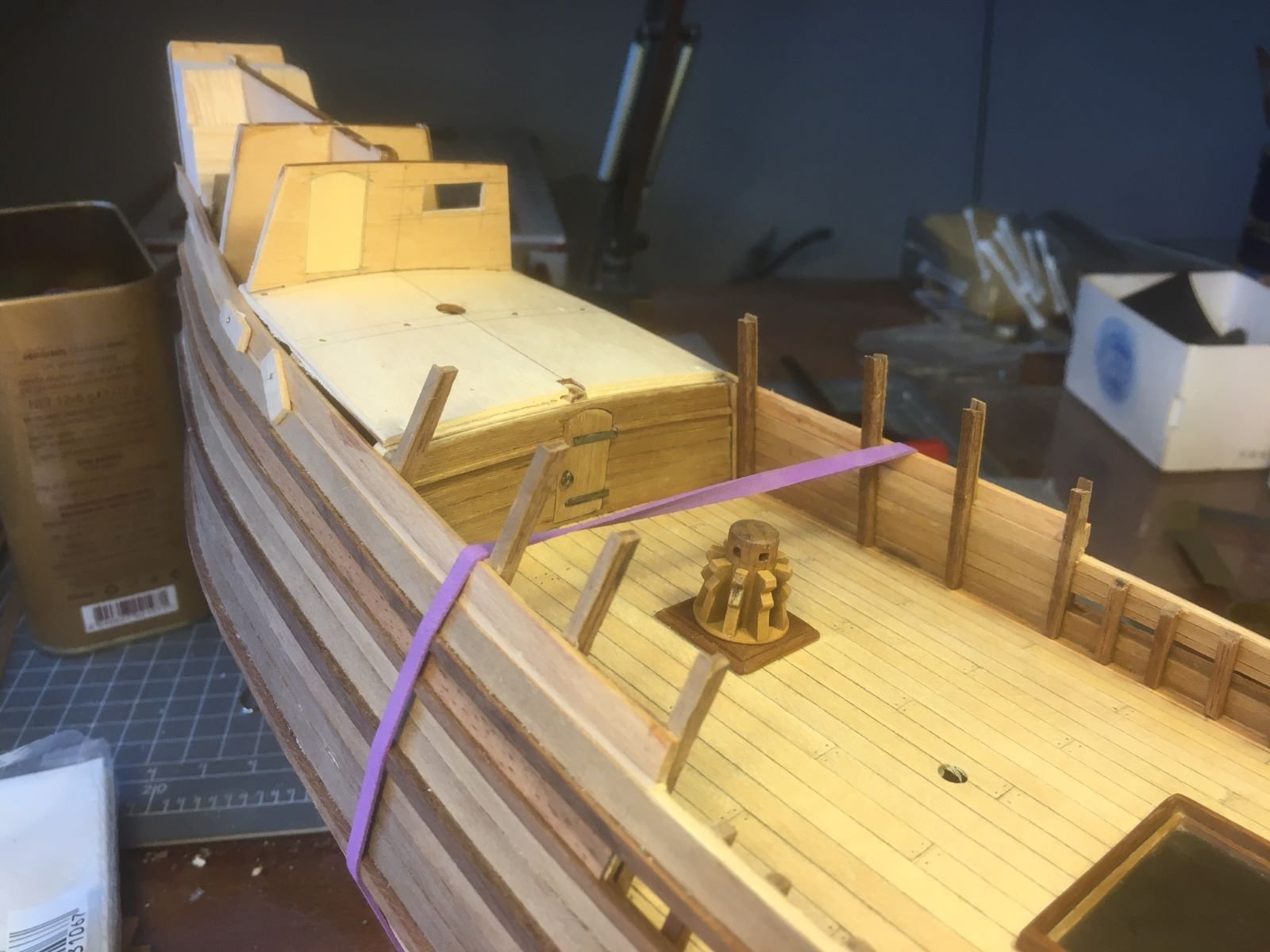
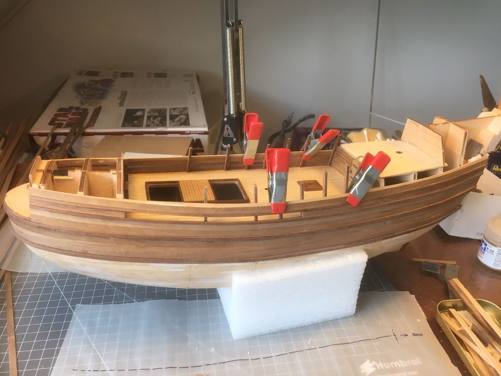
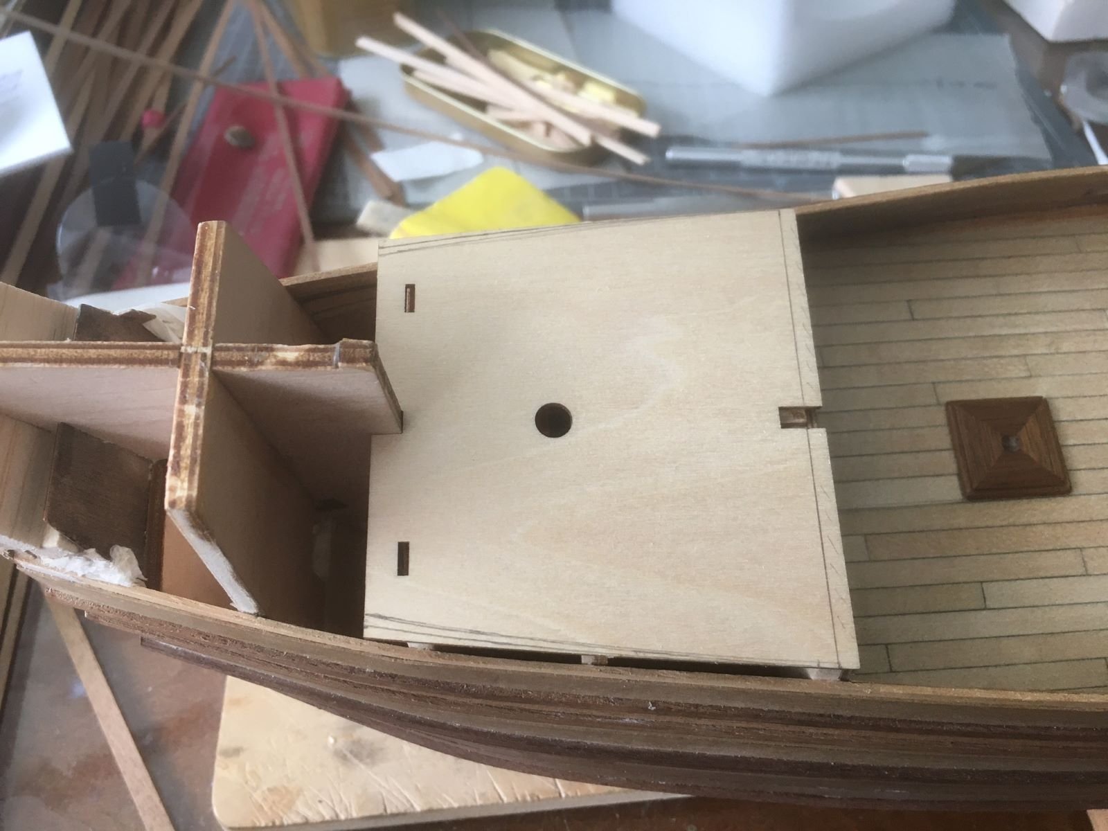
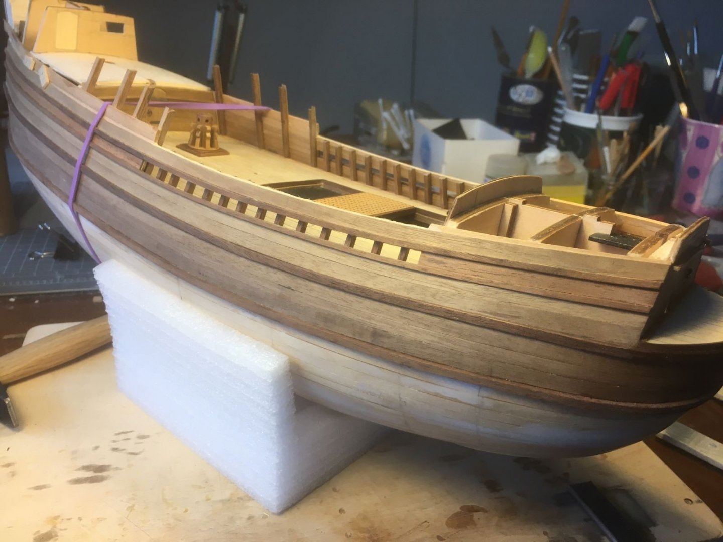
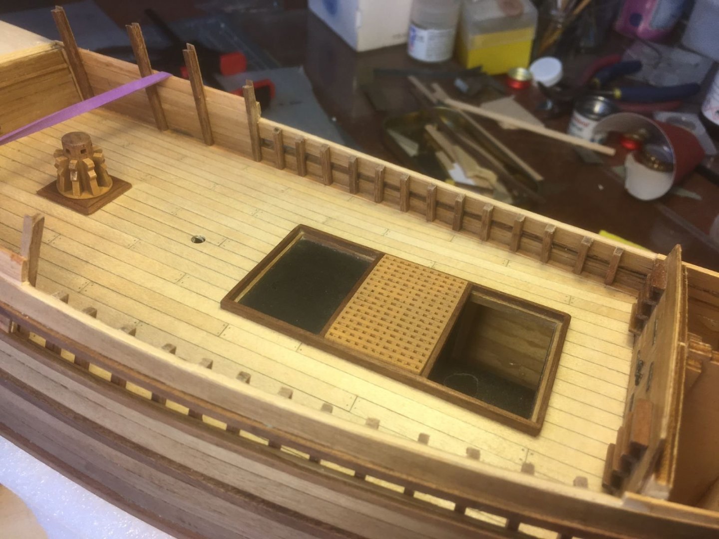
Hi, some small progress with my build, I finally attached all the posts to the inside of the bulwarks and started to work on the main cabin. This is a detail of the deck with the windlass posed in its place: I added pencil dots for the treenails and prepared the bulkhead of the poop cabin: Next, as said, I will have to figure out how to make the mid deck extension. Best regards, Dan.

- 42 replies
-
- 5
-
-
- first build
- artesania latina
- (and 1 more)
-
Thanks Yves, I am glad that you like my build. It takes long for me to get appreciable progresses, partly because I am a slow builder and partly because of the customization I like to implement on this model. Best regards, Dan.
-
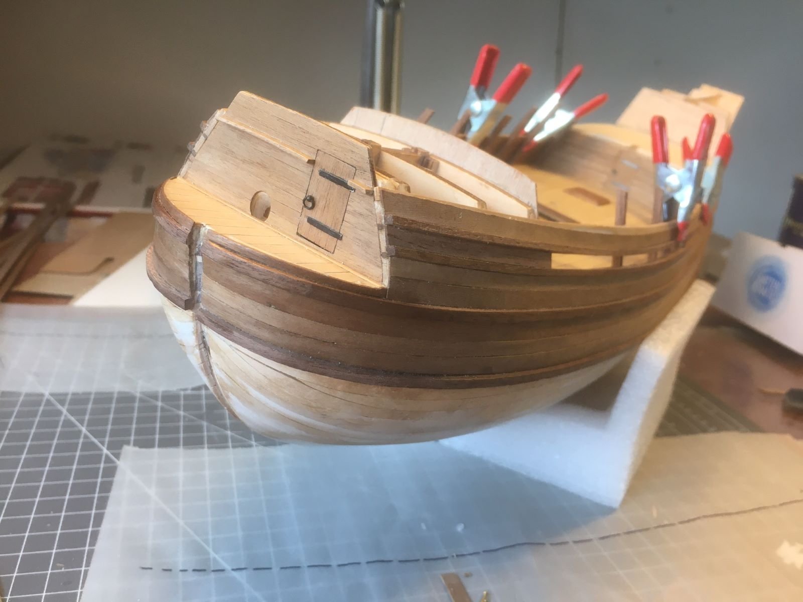
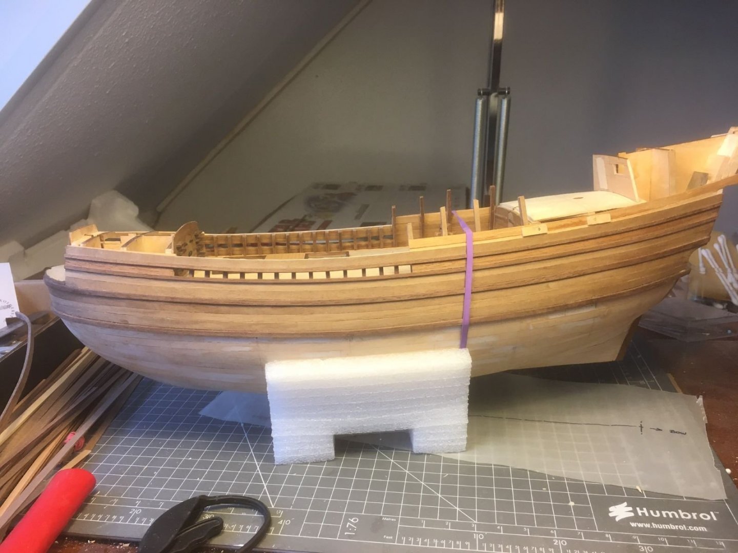
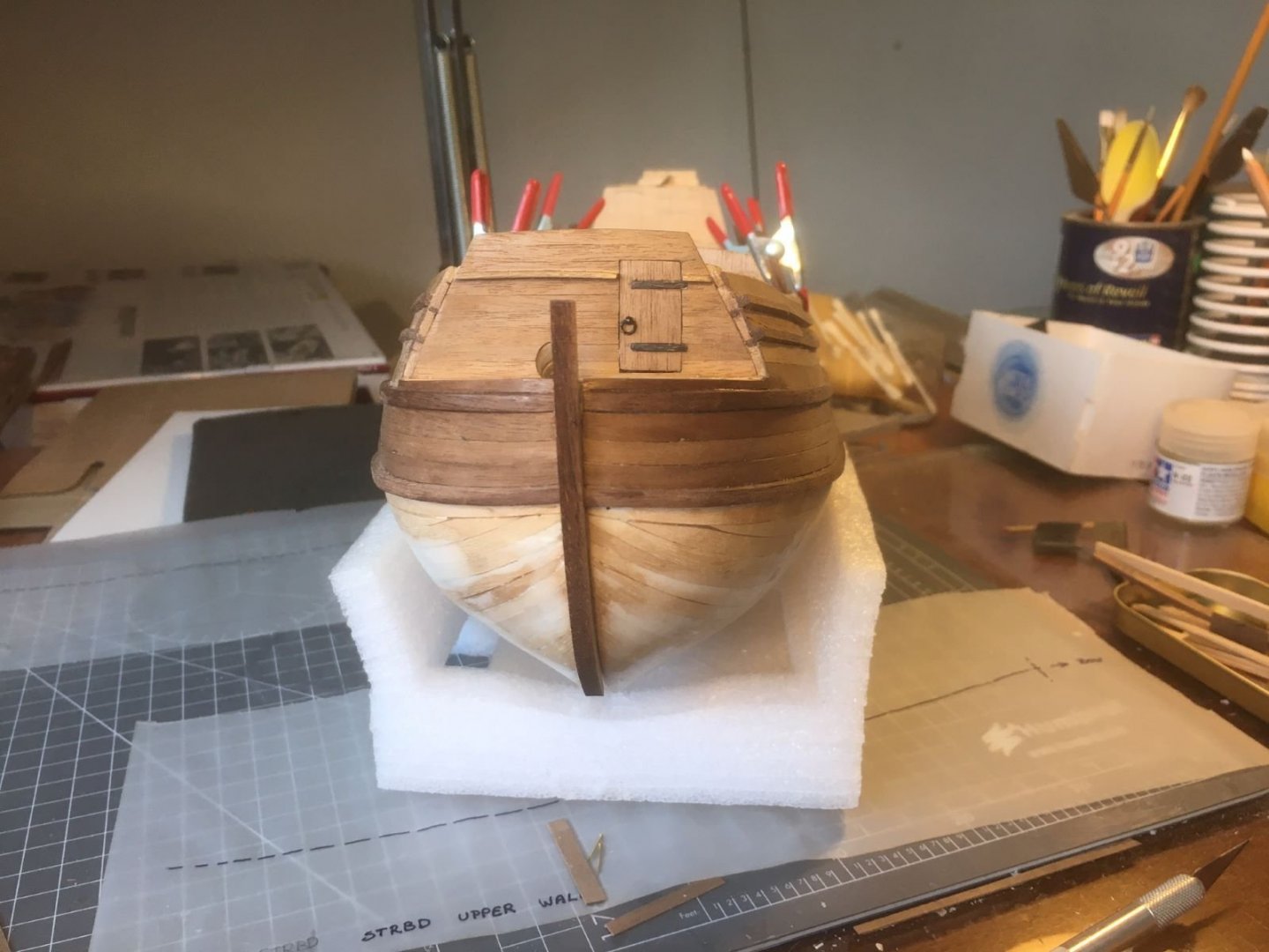
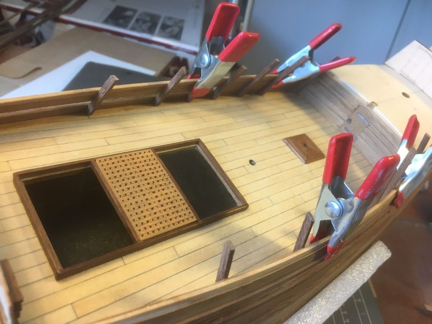
Hi all, I installed also the second large wale which turned out better than the first one (experience counts): This is how the wales meet at the bow once the keel is dry fitted: Then, I also started working on the main cabin deck. Below, the part supplied by the kit is shown. It will have to be slightly modified as indicated by pencil lines. I want to extend this deck forward so to cover part of the main deck approximately down to just before the main mast location. This design is exhibited by the Mayflower replica and is also what can be commonly observed in documentation about ships of the same period. Probably, this extension was a convenient way to extend the deck surfaces and increase the sheltered areas. I need to design the extended part and support it with beams. Meanwhile, I started to add stanchions that will support the beams and the still missing planking as well. I am adding stanchions not in a sequential order, populating gradually all the bulwark. Once finished, the pitch of the stanchions will be smaller that that in the photos. This is all for now, thanks for visiting and please, should you have suggestions on how to proceed, let me know them. Best regards, Dan.


- 42 replies
-
- 6
-
-
- first build
- artesania latina
- (and 1 more)
-
I could not agree more, many times starting a job is the hardest part and waiting for the right moment could mean waiting for ever. In addition, if you make a mistake, probably you can remove the offended balsa block and replace it with a new one, By the way, what is the part you find most difficult, perhaps the poor definition of how the finished object should look like? Keep up the good work, Dan.
- 62 replies
-
- 2
-
-
- amati
- greek bireme
- (and 1 more)


resiz.JPG.b11a7467bfcac104dc7bd1691498077f.JPG)