


DaveBaxt
-
Posts
1,324 -
Joined
-
Last visited
Content Type
Profiles
Forums
Gallery
Events
Posts posted by DaveBaxt
-
-
7 hours ago, AJohnson said:
Hi Dave, sorry to hear about your health issues and hope you are on the road to recovery soon so you can keep building your lovely Diana over the winter period. Looking at the pictures I assume you are like me and build in the garage, hope you have some heating going!
Your improvements to your Diana are looking great.
Thank you Andrew for your kind words ,it is always appreciated. . Hopefully I am not slowed up for to long. I moved into the garage where I have most of my machine tools and whilst working on the hull and have more space. For all the other stuff I have another shed which is much more cosy and well insulated..
- dunnock, AJohnson and Ryland Craze
-
 3
3
-
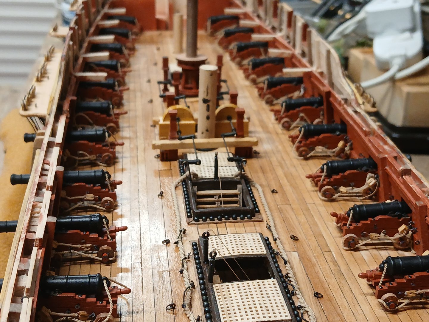
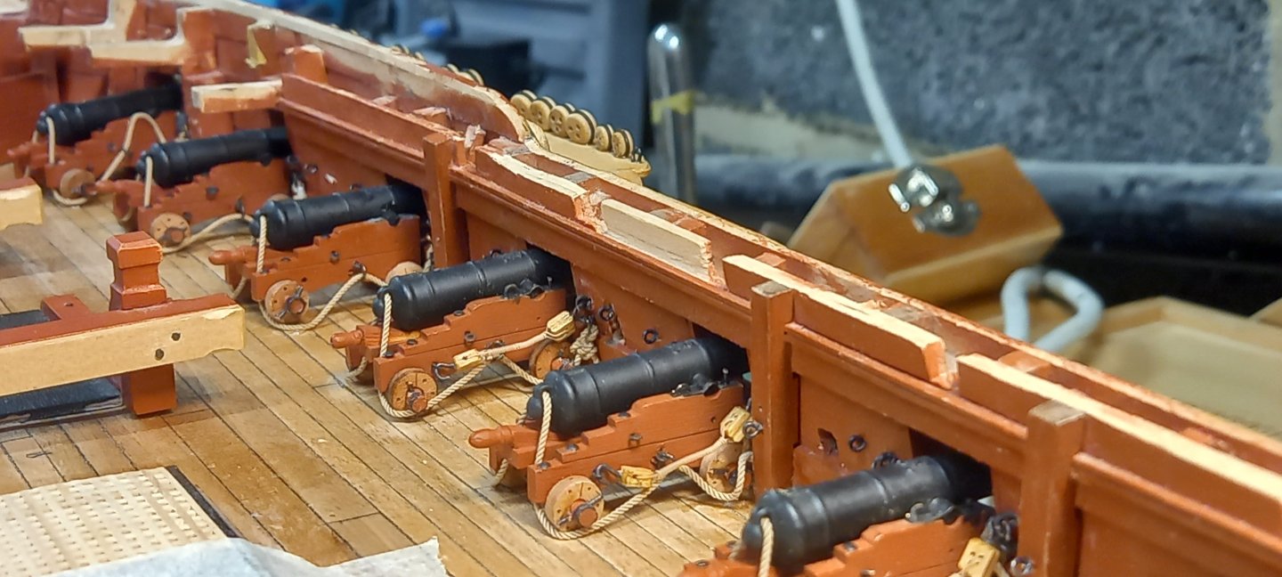
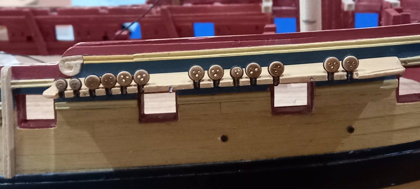
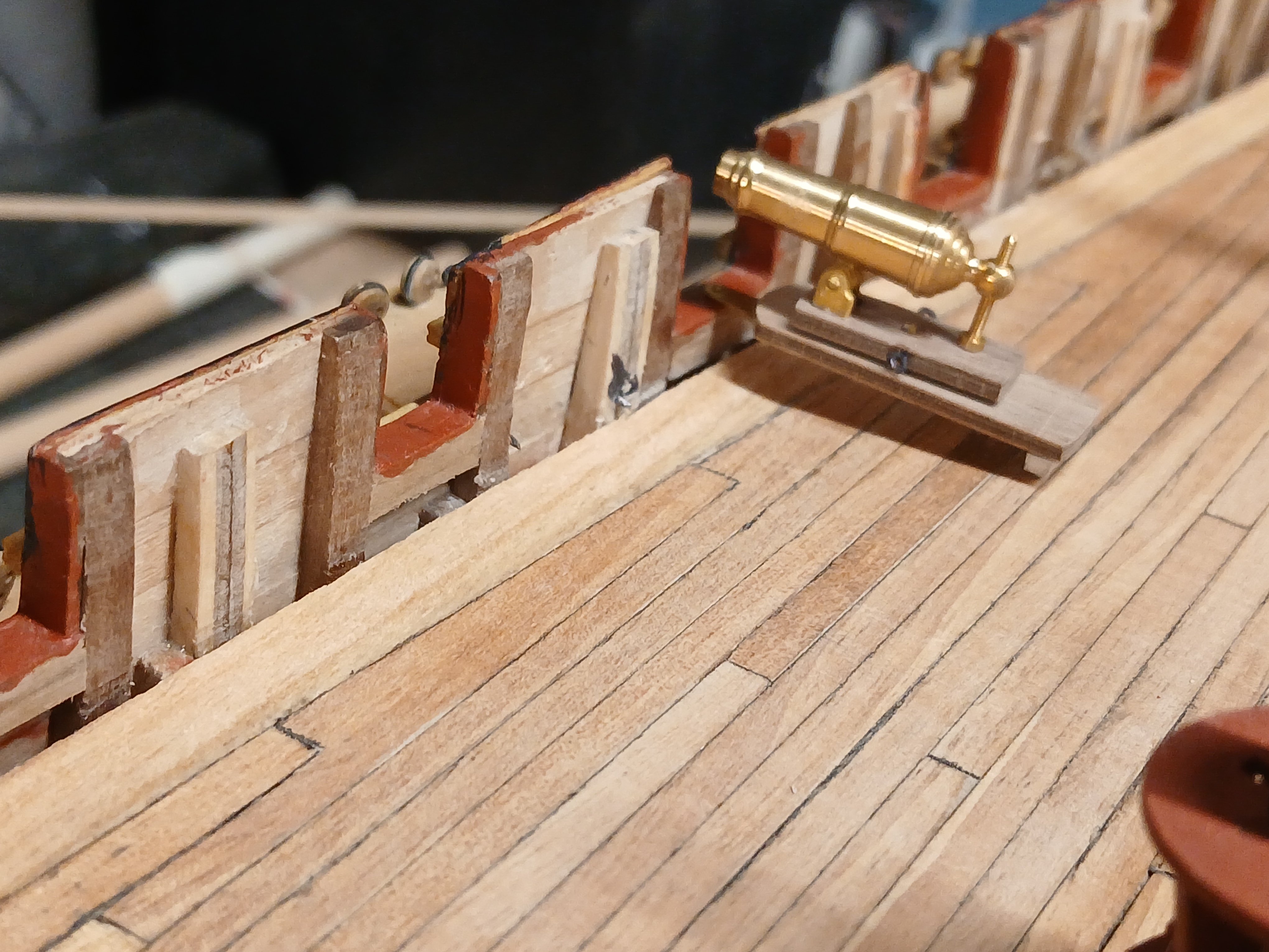
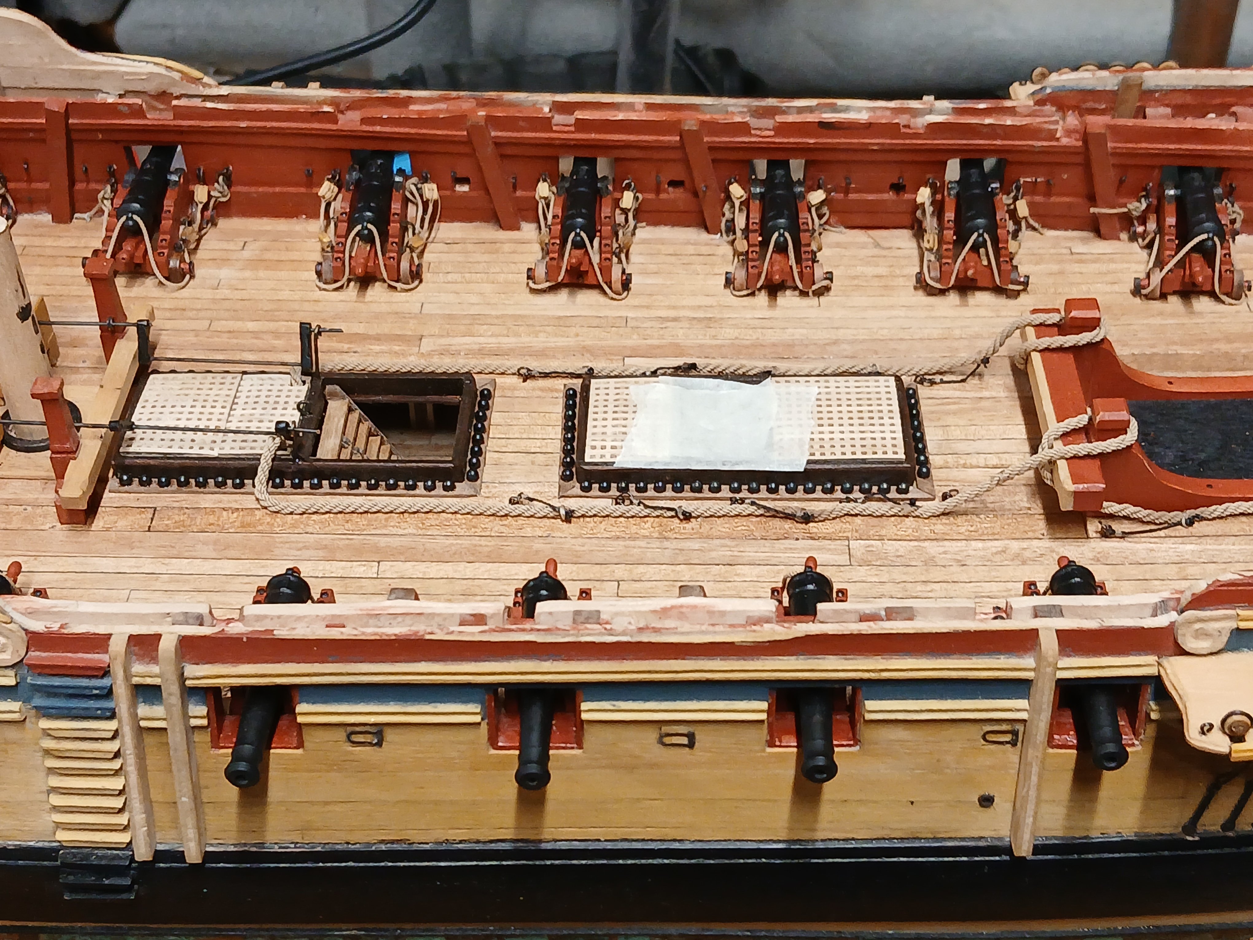
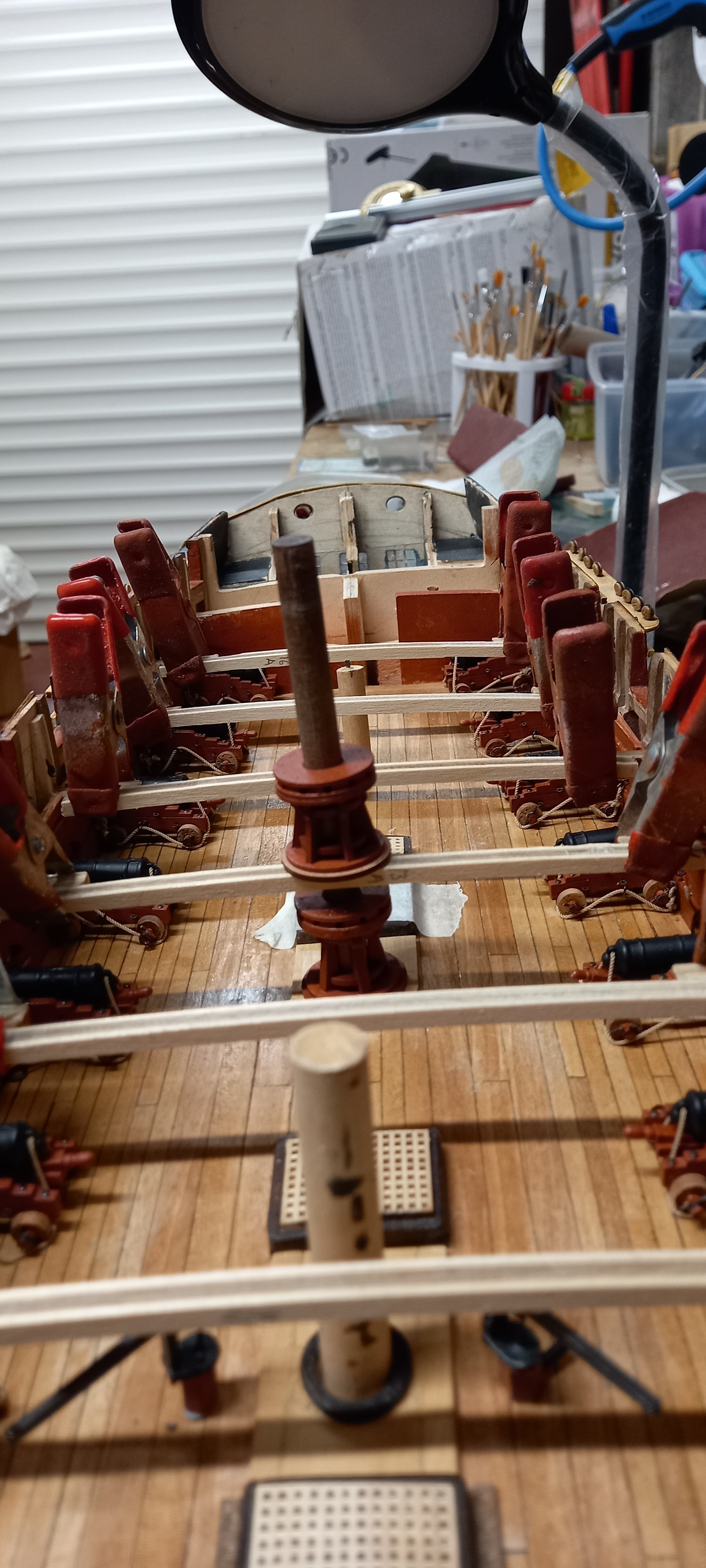
Slow process due to health issues and unable to work on my Diana other than short periods . After laying the deck planking and checking the height of the gun port sill against the 32lb Carronades it was obvious the sill were too high. It was therefore necessary to remove the 1mm thick sill to remove some of the material or then replace the 1 mm thick sill. In order to do this the sides of the gun ports, also 1 mm thick also required removing. Although this was time consuming I eventually managed to complete this. Below is a photo of a 32lb carronade in position and it can be seen not parallel with the deck due to the gun port being too high


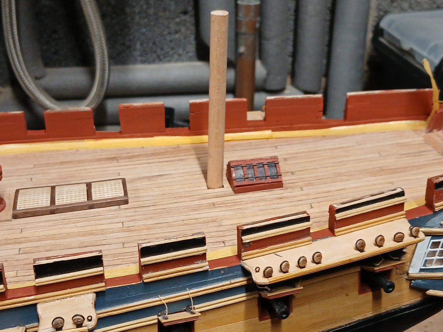
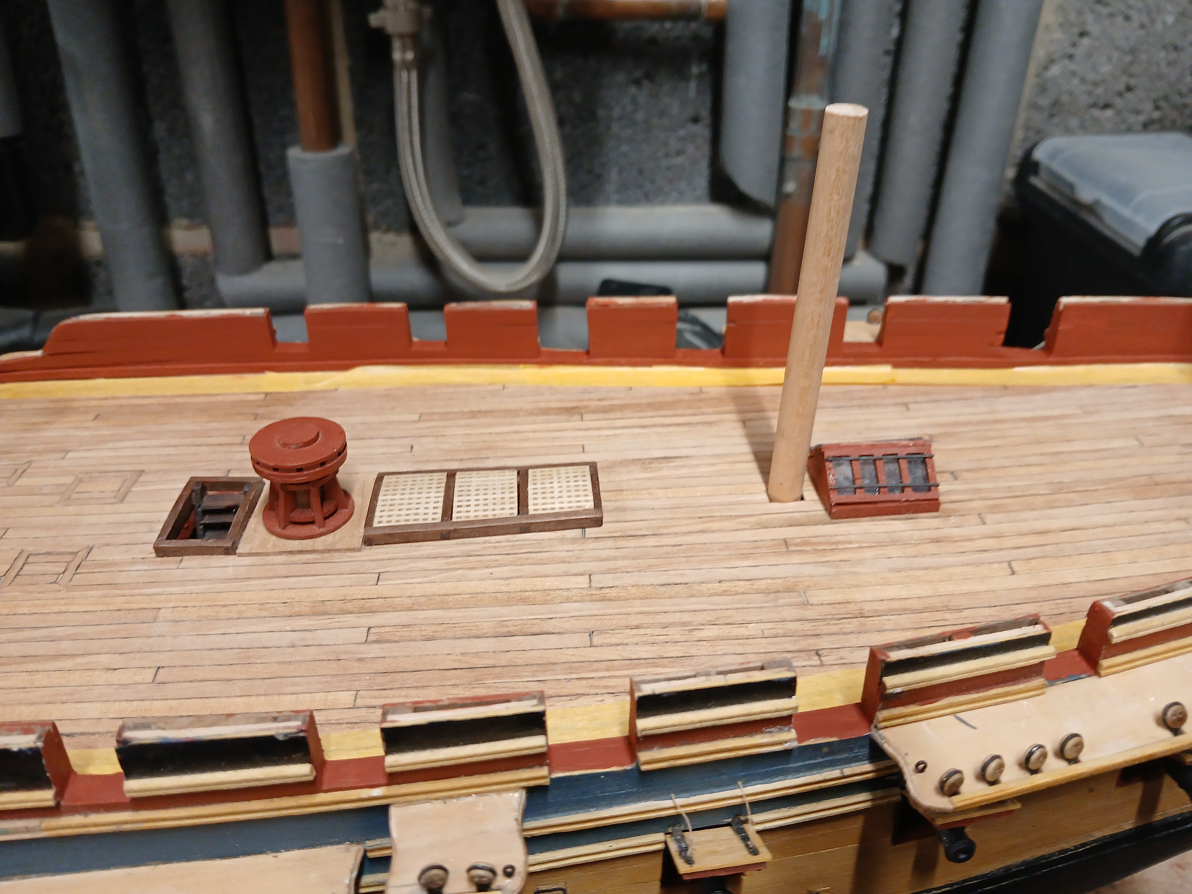
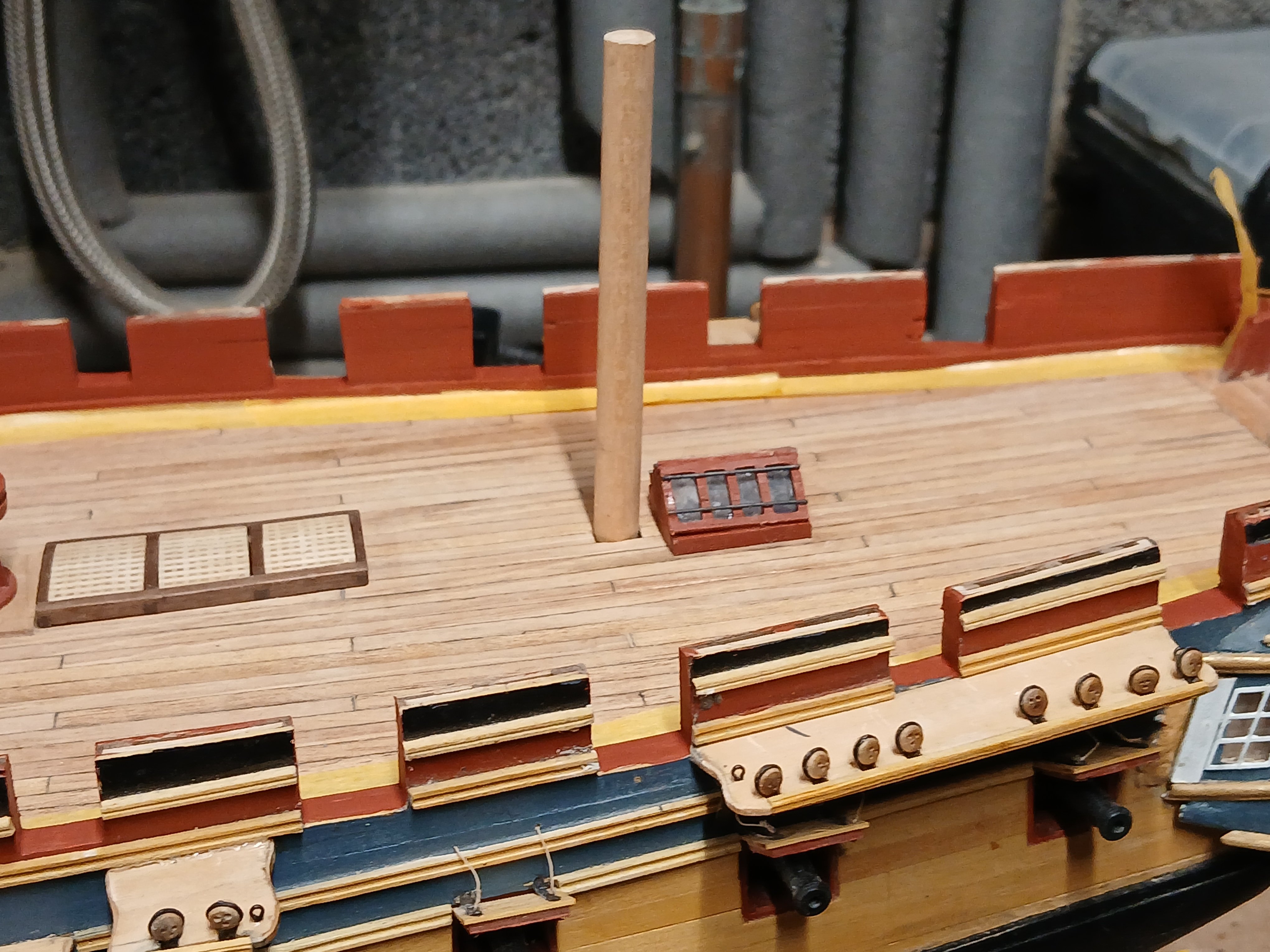
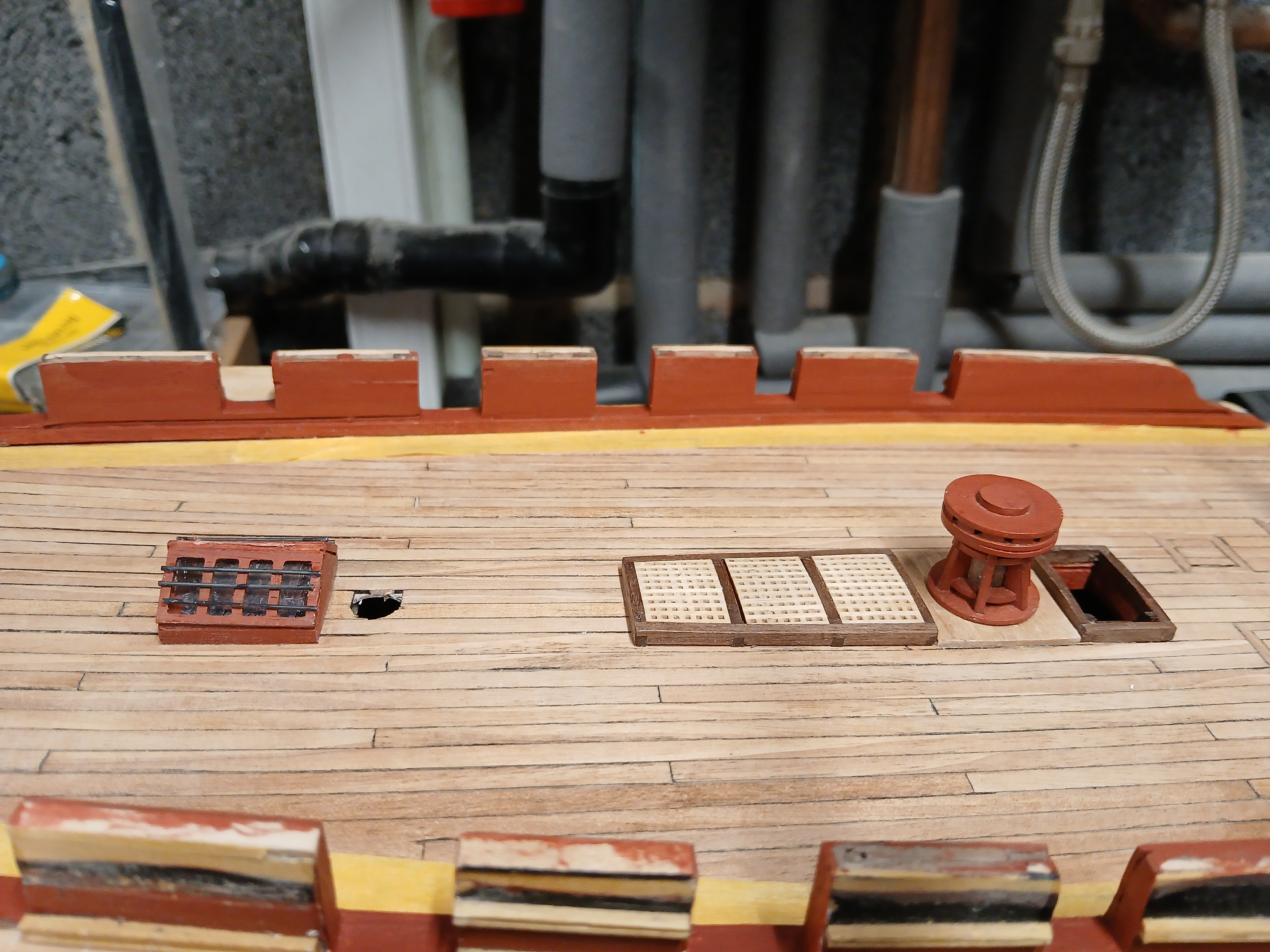
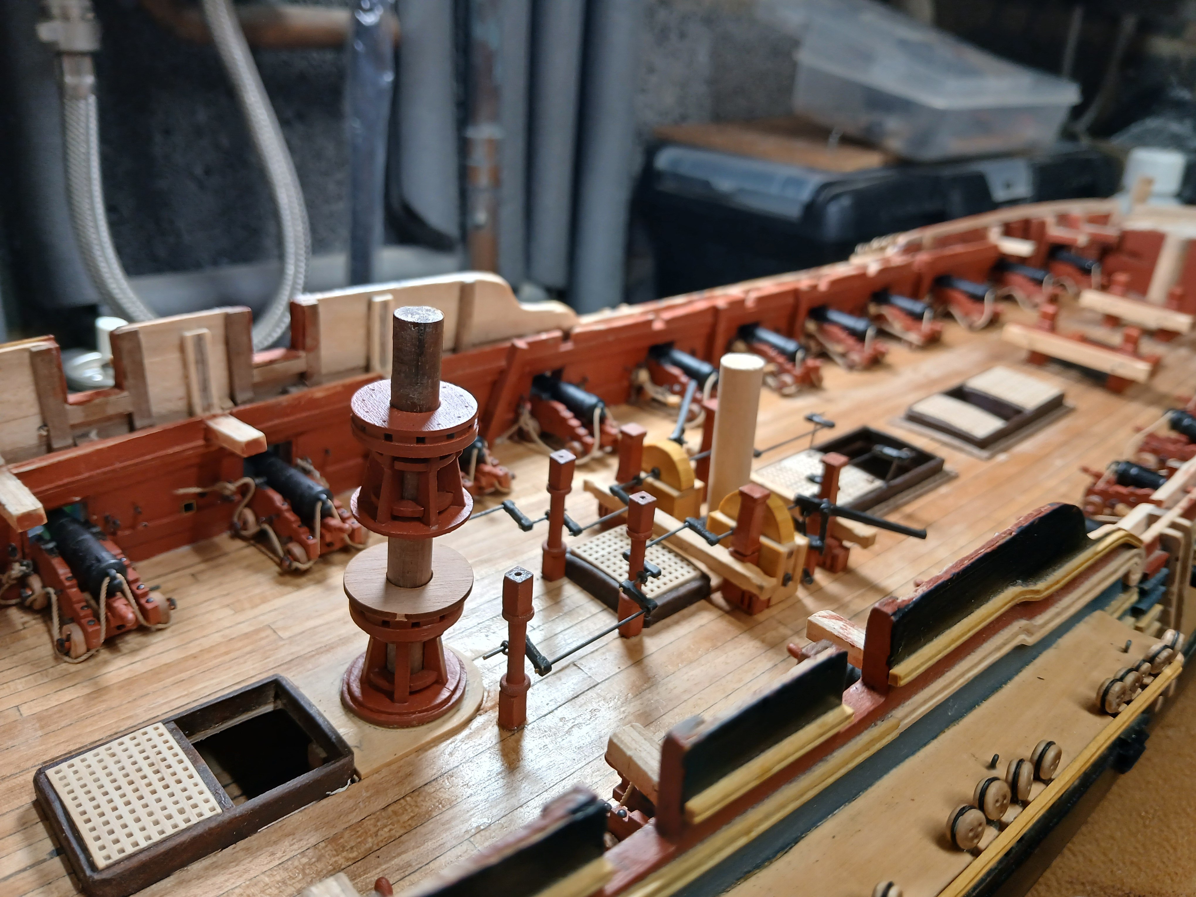
Once the sills were lowerd then it was possible to fit the 1mm walnut planking on the inside of the bulwarks and cut out the shapes of the gun ports.I then moved onto the hatch coamings and various size gratings. Fitting of the stove chimney.

At this point I would like to Thank DavidEN for giving me the idea of upgrading the ships Wheel to 24mm Caldercraft Deluxe wheel as the one supplied by the kit looked to be on the thin side. Next up will be the 32 lb carronade and 9lb Cannon the latter of which I will once again upgrade to that supplied by Vanguard models.I think I can get away with the Caldercraft brass cannon but feel Vanguatd carriages are a definite upgrade. There are still a number of fitting which need to be completed before finally getting to the ships boats. Hoping my health improves so I can get stuck in during these winter days.

- chris watton, Gregory, dunnock and 7 others
-
10
-
-
-
-
On 8/23/2024 at 9:50 PM, No Idea said:
I use this glue exclusively - I have never found a better wood glue and it is extremely strong
I second that I used this on the frame work of my POB Diana kit build. and just run it along the edges after assembly and I found it to be a very strong and an easy way to assemble parts. I am hoping to use it more extensively..
-
-
5 hours ago, druxey said:
Only the early carronades in the 1780's were 'outside principle' mounted. By the 1790's they pivoted inside the ports and muzzle extensions added to direct muzzle flash away from rigging.
Thank you Druxey for clearing that up for me. I didn't know about the muzzle extensions either, so appreciate that little gem too.
- thibaultron, mtaylor and AJohnson
-
3
-
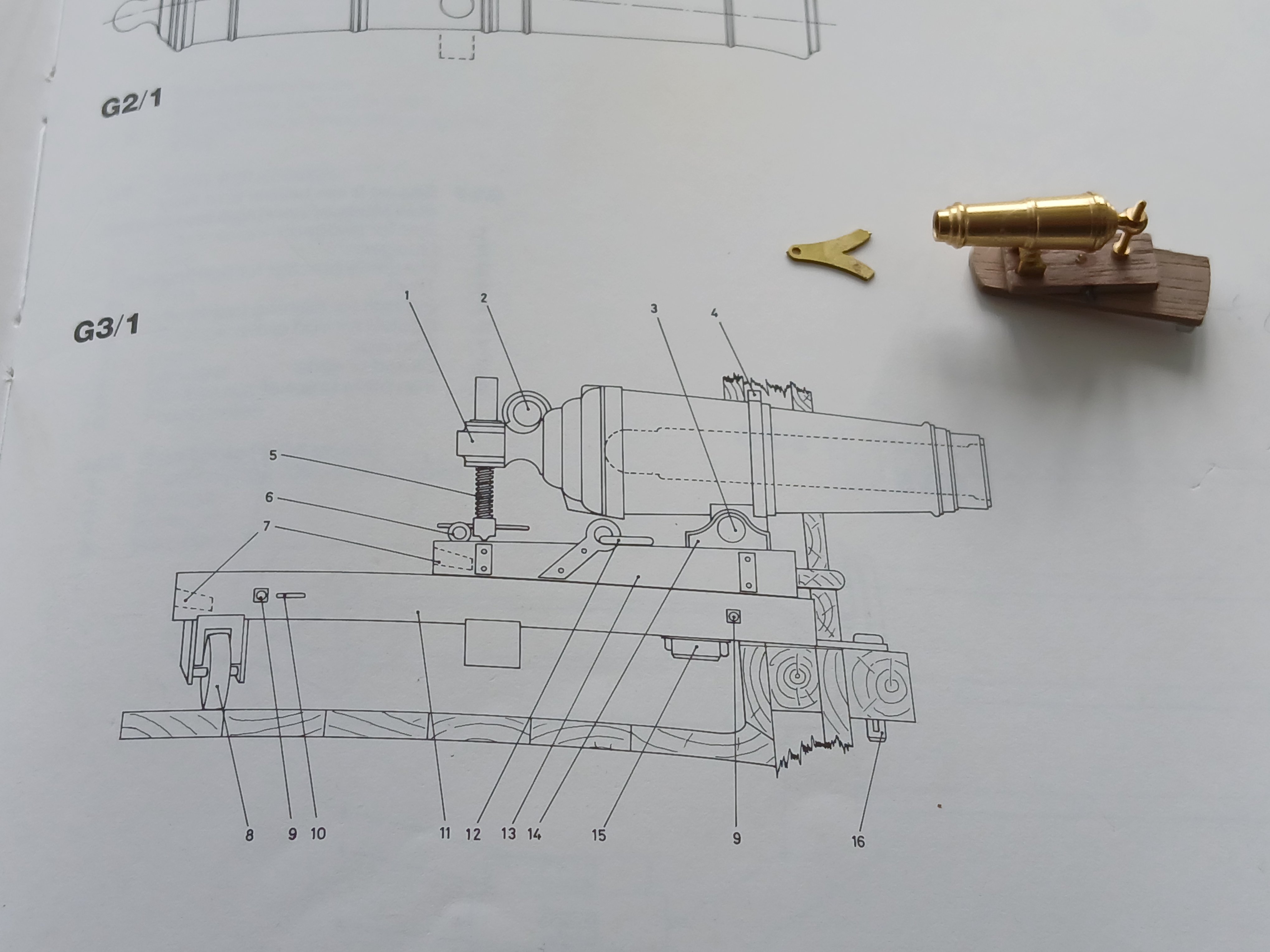
According to Brian Lavery book 'The Arming and fitting of English Ships of war 1600 to 1815' The Sliding bed of a Carronades where secured either on the inside of the bulwark or the outside but I am unsure which way is likely to be the case on the HMS Diana 1794. Here is a photo of an assembled 32lb Carronade which came with the kit

According to the book AOTS Diana the front of the carronade is secured by what is called the fighting bolt through the iron bracket and a piece of wood on the outside of the bulwark and below the gun port. If this happens to be the case then unfortunately the gun ports for the are too high and will require lowering. It will also be necessary to attach a piece of wood to the outside lower part of the gun port . This does not appear to be shown on any of the other drawings. Another way to get around this without taking any drastic measures would be to attach the brass bracket on top of the sliding bed rather than underneath as suggested in the instructions.This would then allow the bracket to slide over the sill of the gun port. I know in my heart that this is probably incorrect but it would be a shame to alter the gun ports at this stage of my build. Any thoughts or suggestions as to the best way around this ,if in fact the fighting bolt is in fact fitted on the outside of the gun port sill. Thank you once again for your help and patience. Best regards Dave

- AJohnson, Thukydides, thibaultron and 1 other
-
4
-
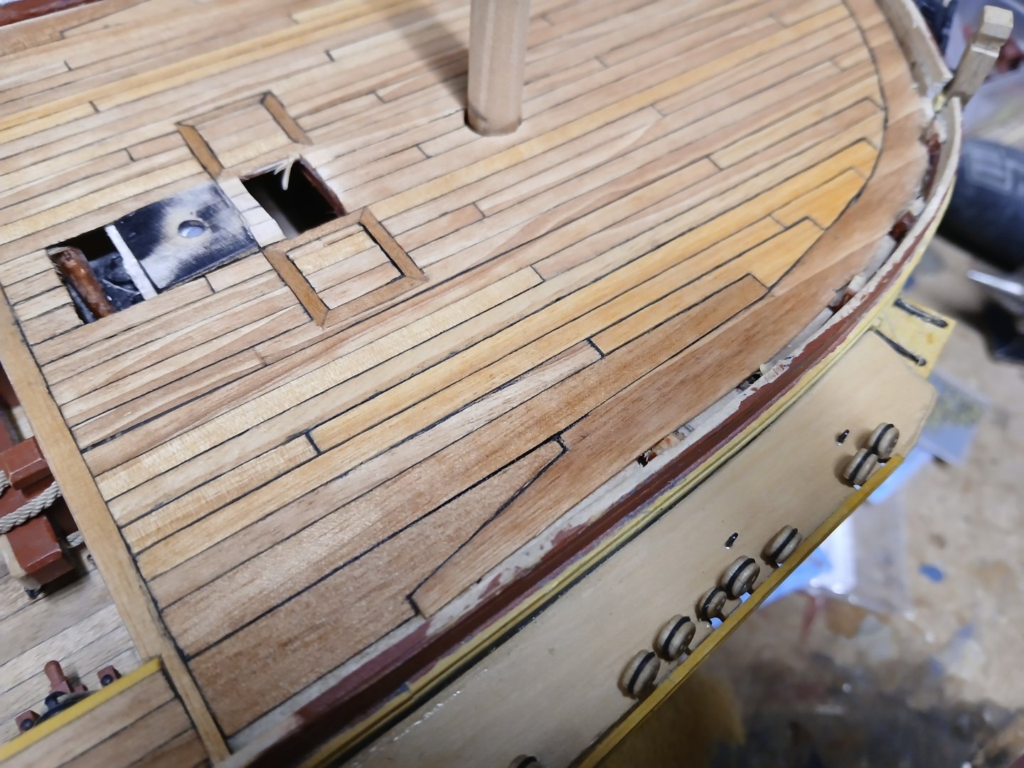
Completed planking the upper deck, mainly using 1 x 4 mm Tanganyka strips which came with the kit together with some extra wider strips used for joggling. I also used quite a lot of 1mm Tanganyka sheet which was quite difficult to cut and split along the grain. In the end I temporarily glued a 1.5 mm sheet of ply to the Tanganyka sheet to strengthen the Tanganyka whilst cutting and shaping the waterway . I used the same planking pattern as the lower decks(4) with the length of each plank 180mm and staggered 45mm. Unfortunately there was quite a big difference between the colours of the Tanganyka sheet and the strips but hopefully this will not be too noticeable once the decks are covered with the numerous fittings. I also used the drawings off the AOTS Diana book as to which deck openings had either coamings or scuttles and ended up with a lot of wasted Tanganyika pieces due to attempting to cut this wood along the grain but hopefully I have made a reasonable job of this.
I would like to thank Andrew Johnson for giving me the idea of using one of the many Liberon products on offer for trating the deck This time I have tried their superior clear oil which I think shows the Tanganyka wood off quite nicely.
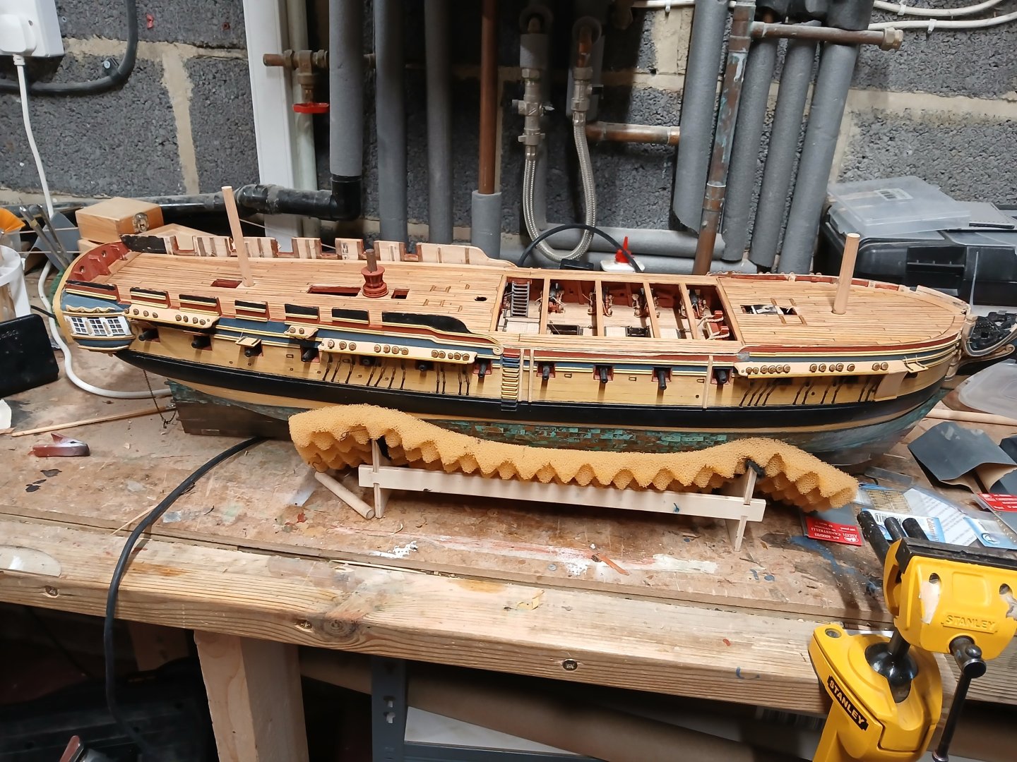
Next up will be the hatch coamings, gratings and the numerous upper deck fittings. Still a long way to go as am well past the 18 month mark now and no end in site yet but she is beginning to look a bit like a late 18th century frigate..


- PaddyO, Thukydides, KARAVOKIRIS and 7 others
-
10
-
-
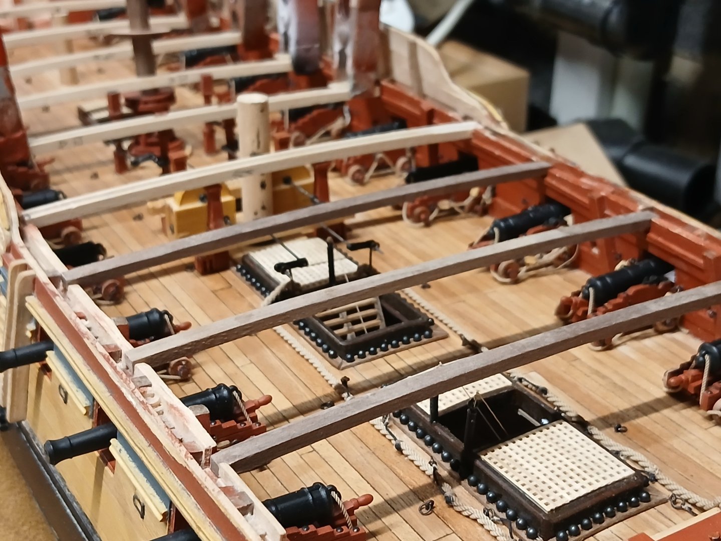
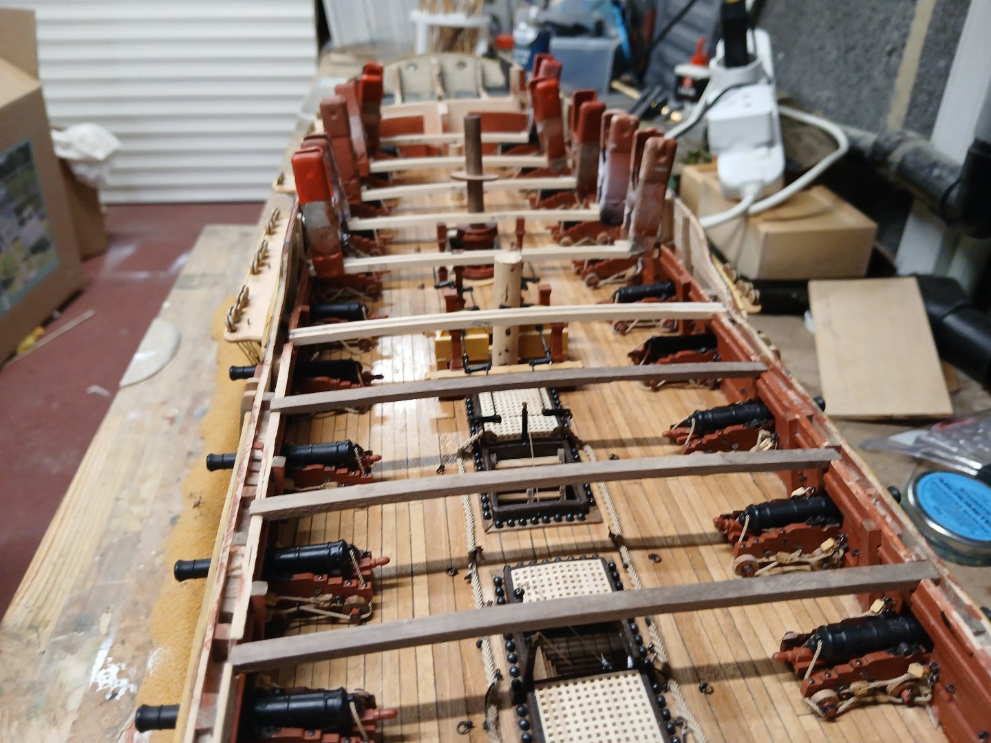
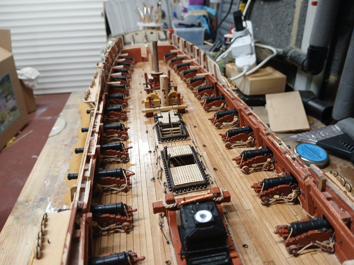
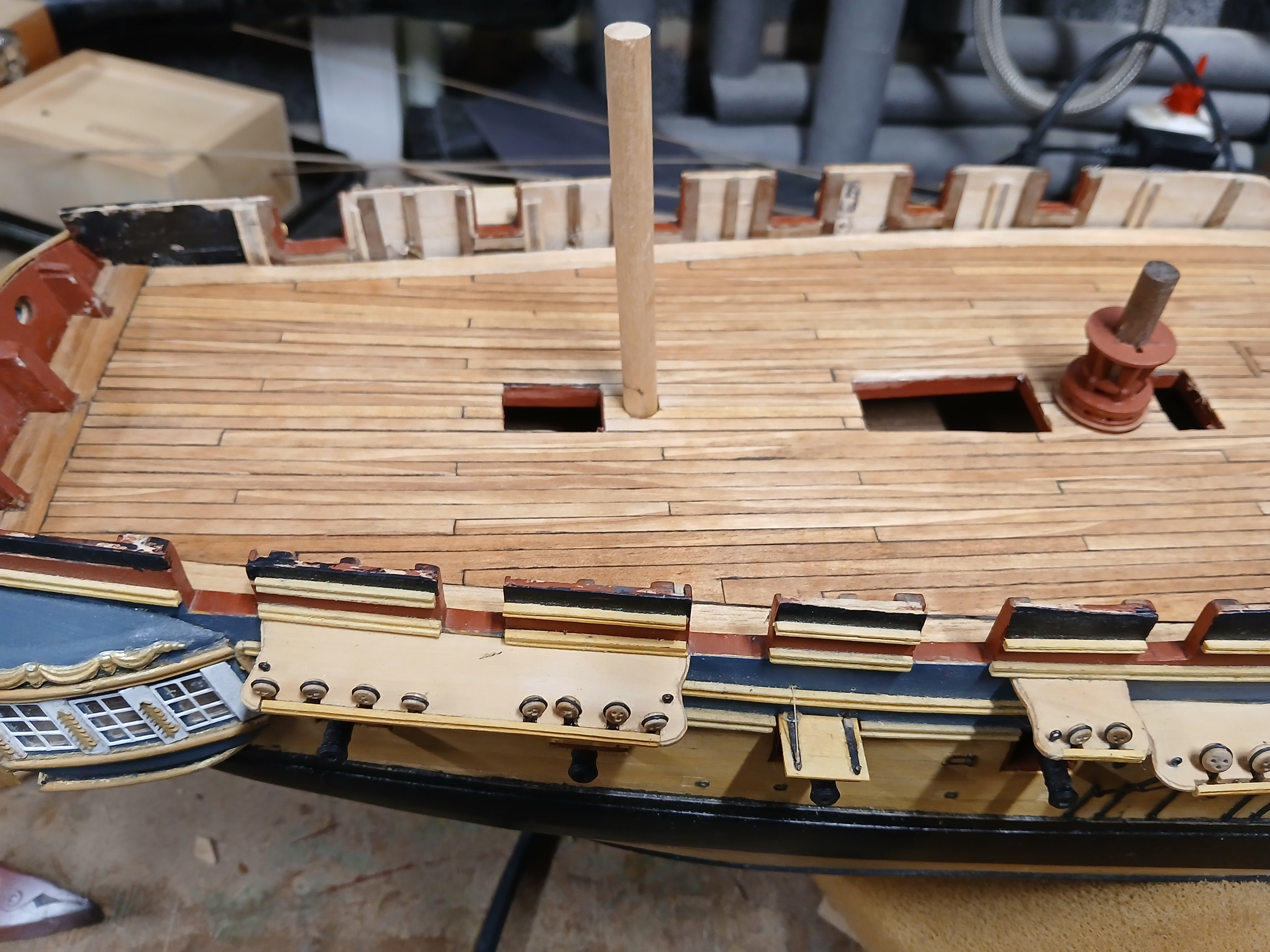
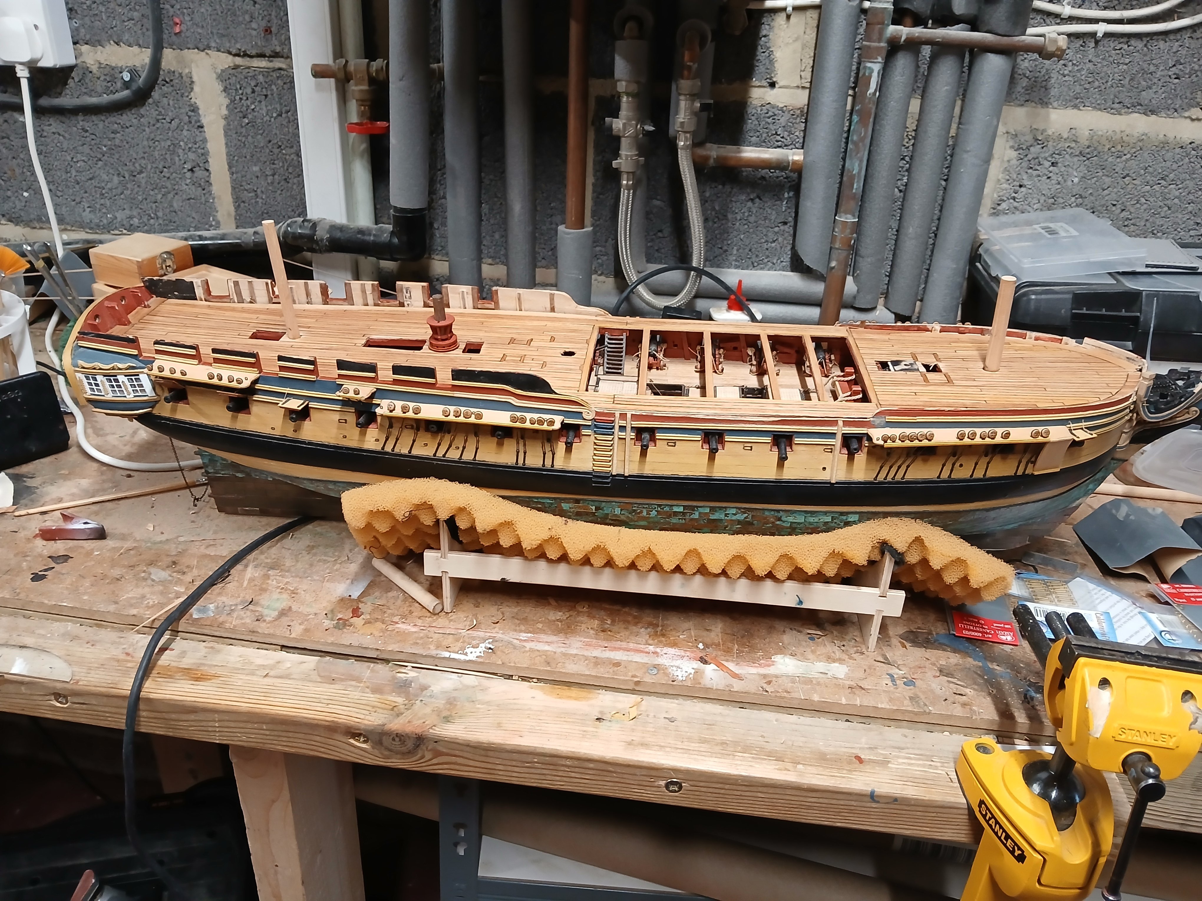
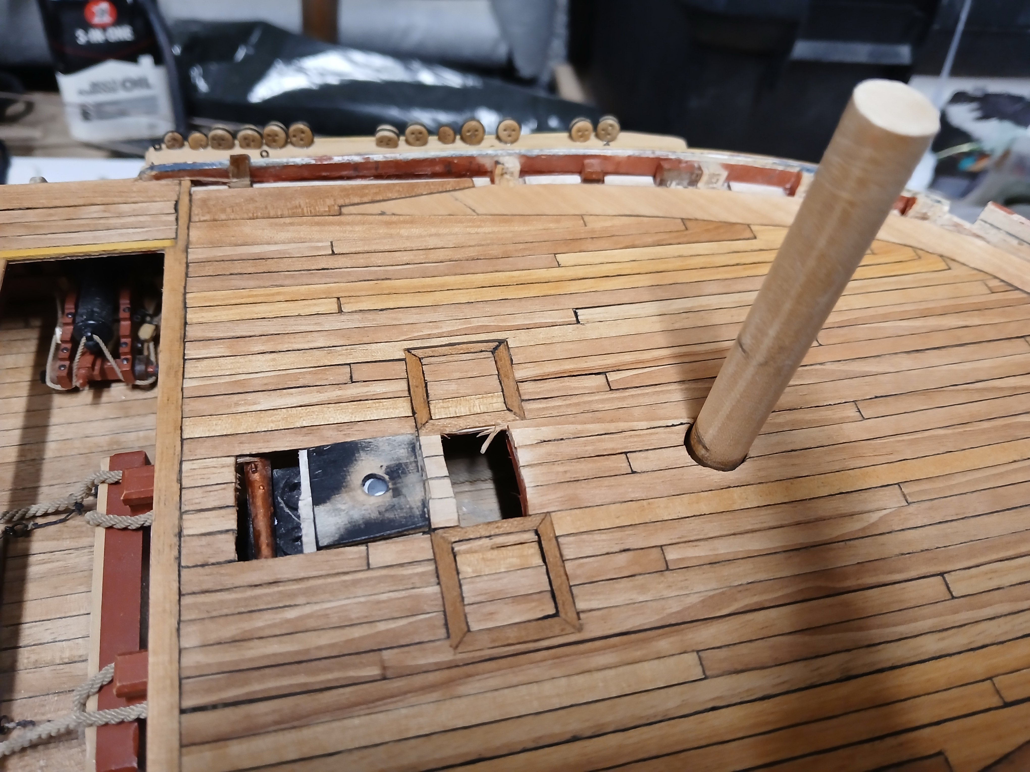
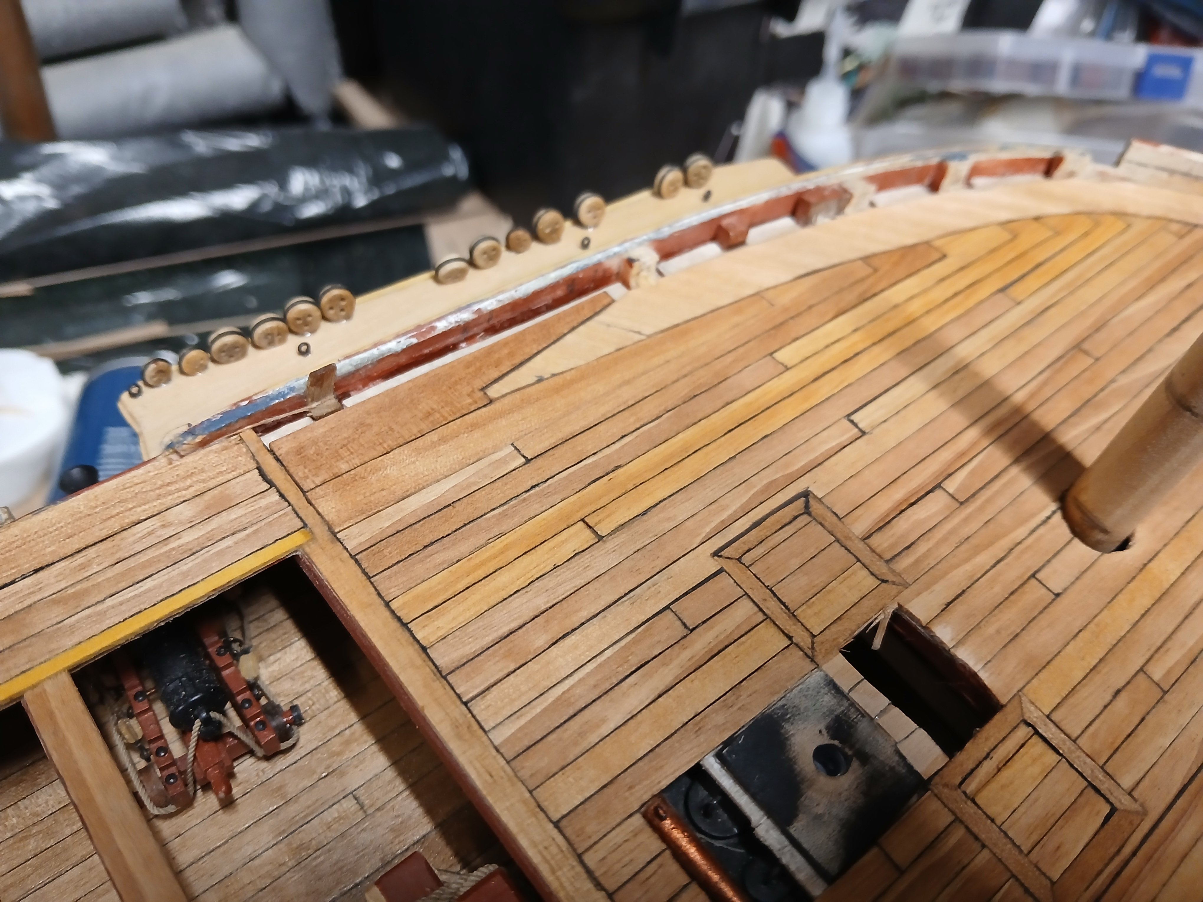
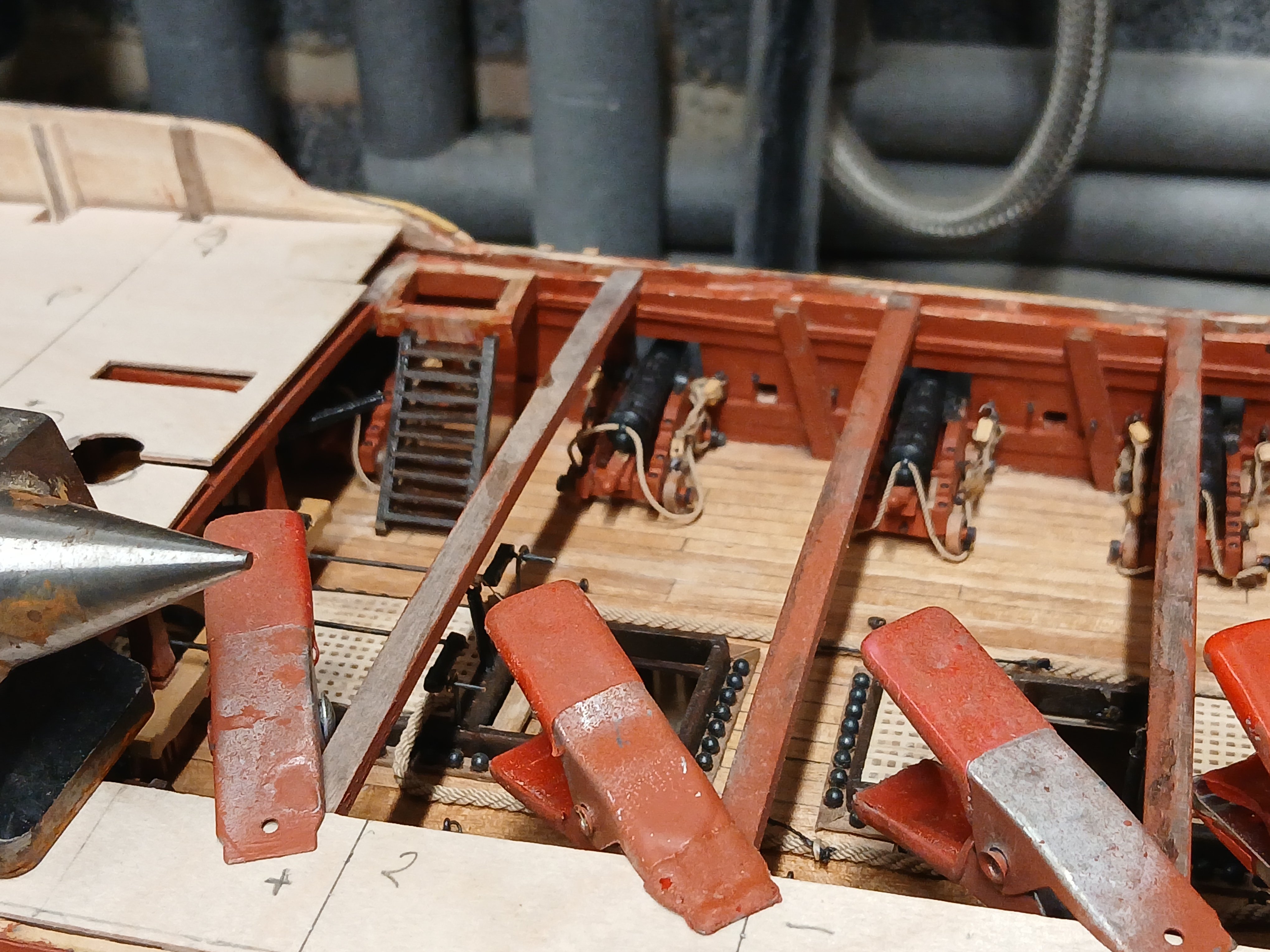
Further preparation made for fitting of the forcstle and quarter decks and fitting of additional beams. For some reason several of the deck beams had to b moved so that they did not appear in the middle of the hatch openings and scuttles I also fitted a number of the carlings in-between the deck beams. so as to line up with the edges of the hatch openings. This also would give additional strength to the deck. I also made a frame work for ladders supports and made up a couple of ladders either side of the gangways.

I then marked off the forcsle and quarter decks to take the 1 to 4 deck plank pattern which is the same configeration as the lower gun deck planks. I also cut the deck into 4 pieces as I thought it would be easier to handle in smaller section when gluing to the deck. Before fitting the deck I made a final check to everything on the lower decks as they should be and finally fitted the elm tree pumps.
.thumb.jpg.83cb5623c163ae8044b4b21cd3a7ed8b.jpg)
.thumb.jpg.e848a108a5c5b12c2bff3c952015e0fc.jpg)
.thumb.jpg.274d6c8a3aacb31312e7eec3bd1f0193.jpg)
.thumb.jpg.666405af43968ade6d9f3c35e6c93786.jpg)
I am now going to take a bit of a break and will be off on holiday so it might be sometime for the next update
-
-
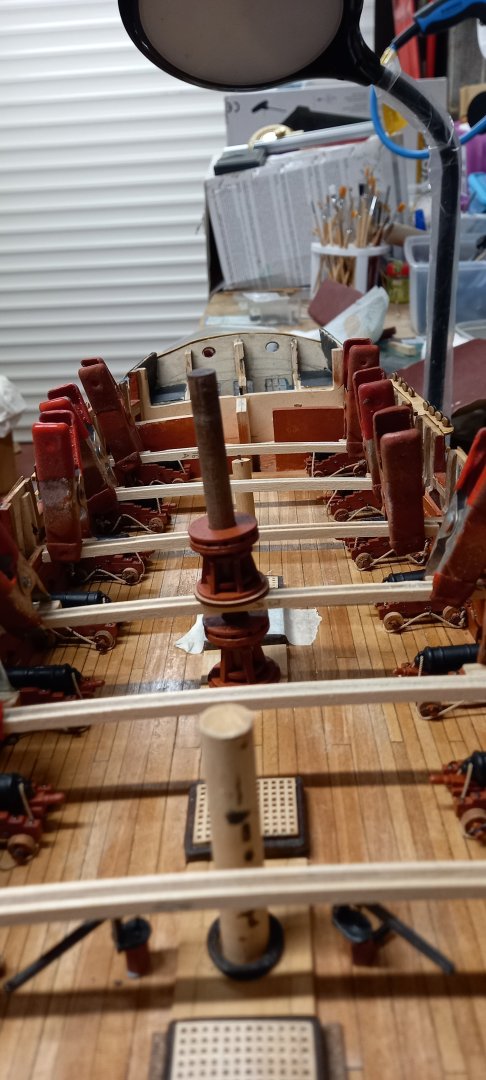
Secured the bitts into position and made up the chain pumps handles from 0.8mm brass wire and the connection pieces from 2.7mm square boxwood and reduced to 2mm square and shaped

Fitted the 18lb Cannon balls into the racks at the sides of the hatch coatings and making a start on fitting the anchor cable (2.1mm tan from Ropes of Scale)and making up a number of stoppers for securing the anchor cable to the lower decks. Finished off the eyebolts and rings for the gun tackle but left off the tackle for withdrawing the gun as I thought this would just clutter up the deck and believe this would be stored away when not in use anyway. made up stantions from the same fittings used for ther chain pumps handle bushes. I have left off the chain pumps until the last in fear of knocking them whilst work on the beams etc.

.thumb.jpg.1d70f626b943327c6ac69c65e2f72aef.jpg)
Next up will be the fitting of the deck beams and skid beams prior to fitting the upper deck. A shame to cover a lot of the work over the last few months
.thumb.jpg.a9e3c78f858473cc58c49533bf03ba89.jpg)
.thumb.jpg.b922530d7436a45db602d6e266e9315e.jpg)
- KARAVOKIRIS, DavidEN, CTDavies and 8 others
-
11
-
Absolutely stunning workmanship and an inspiration to us all. I only wish I had found this log earlier on your journey.
- Ryland Craze, AJohnson and Thukydides
-
2
-
 1
1
-
-
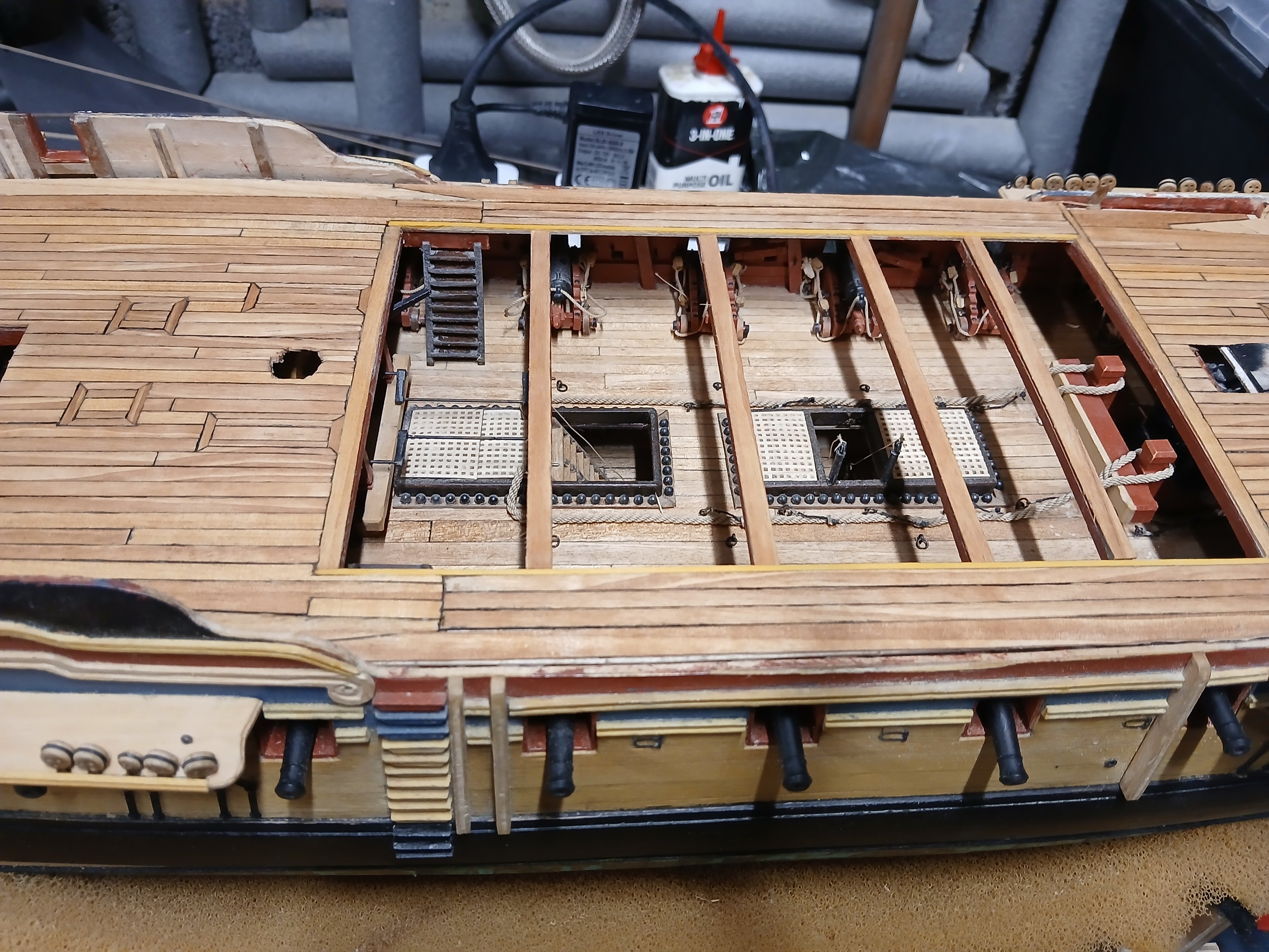
Slow progress during the summer season due to other commitments .After sanding down the gun deck in the areas where the 18LB Cannon would sit I secured the tackle to the 18lb Cannon to the decks using thick super glue and fitted 0.7mm breeching ropes and 0.25mm gun tackle to the Cannon which can be seen at the midship section through the opening at the top deck. .
.thumb.jpg.dee888aabec6f3f92395eee956f142f3.jpg)
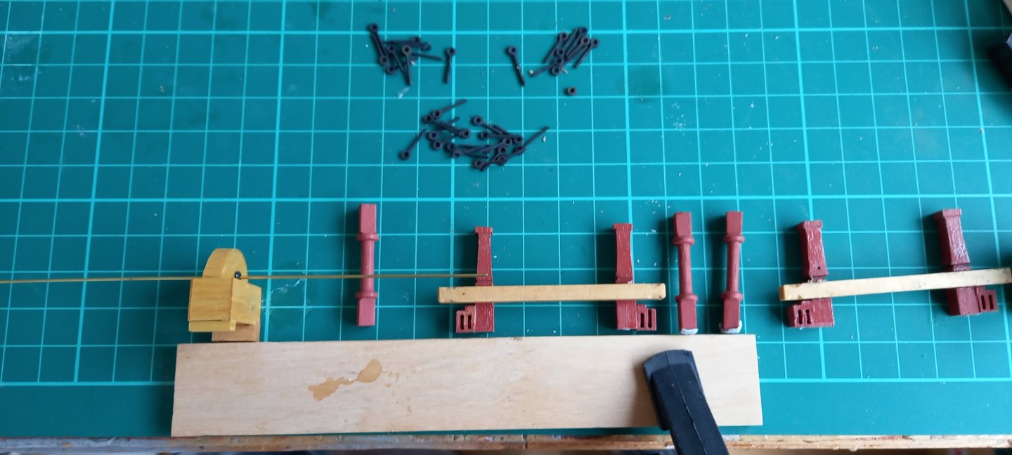
I have made a start on securing the deck fittings and finishing off some bits and pieces, including the rudder chains and more deck fittings such as the chain pumps and lower capstan which was supplied by Vanguard models as I wasn't,t happy with one that came with the kit.
Rudder & rudder chains fitted
Lower capstan with top capstan not glued into posiition
Fitting of bushes for chain pumps handles
.thumb.jpg.235ce240931050801468ab4cc95c3d45.jpg)
- KARAVOKIRIS, Ronald-V, DavidEN and 7 others
-
10
-
-
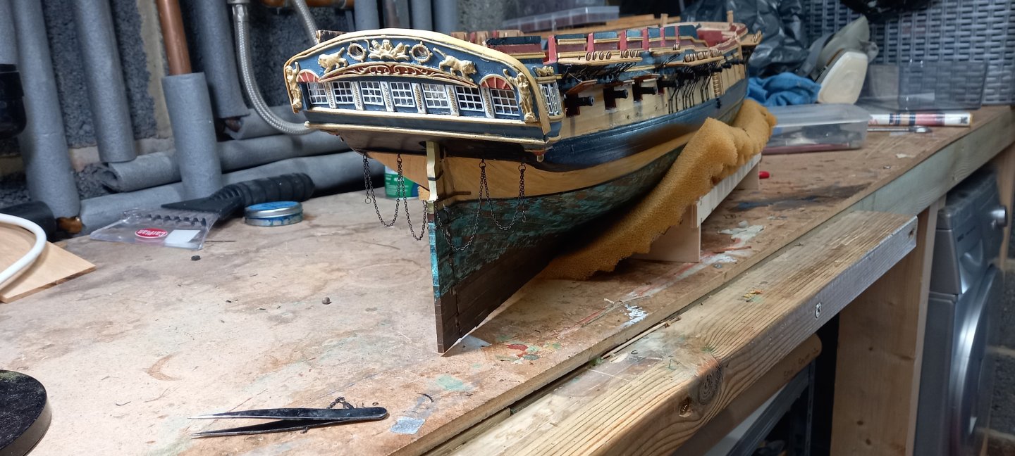
-
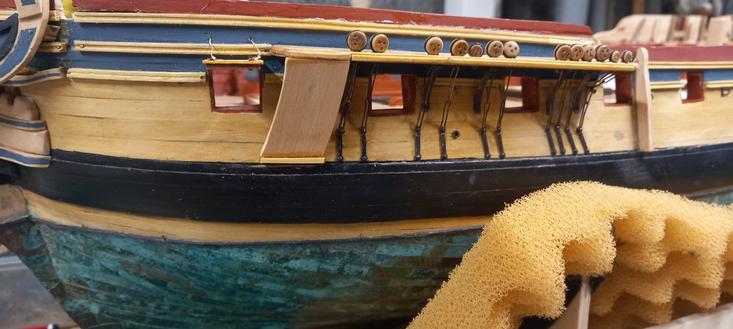
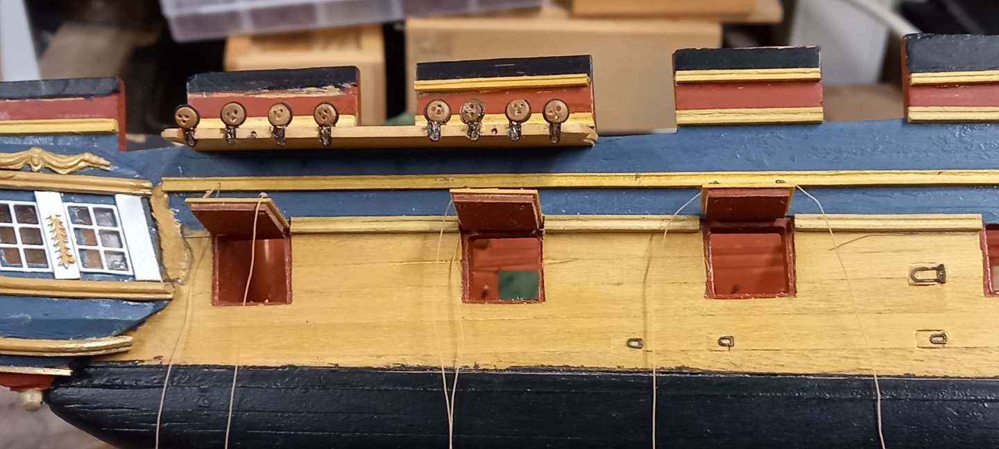
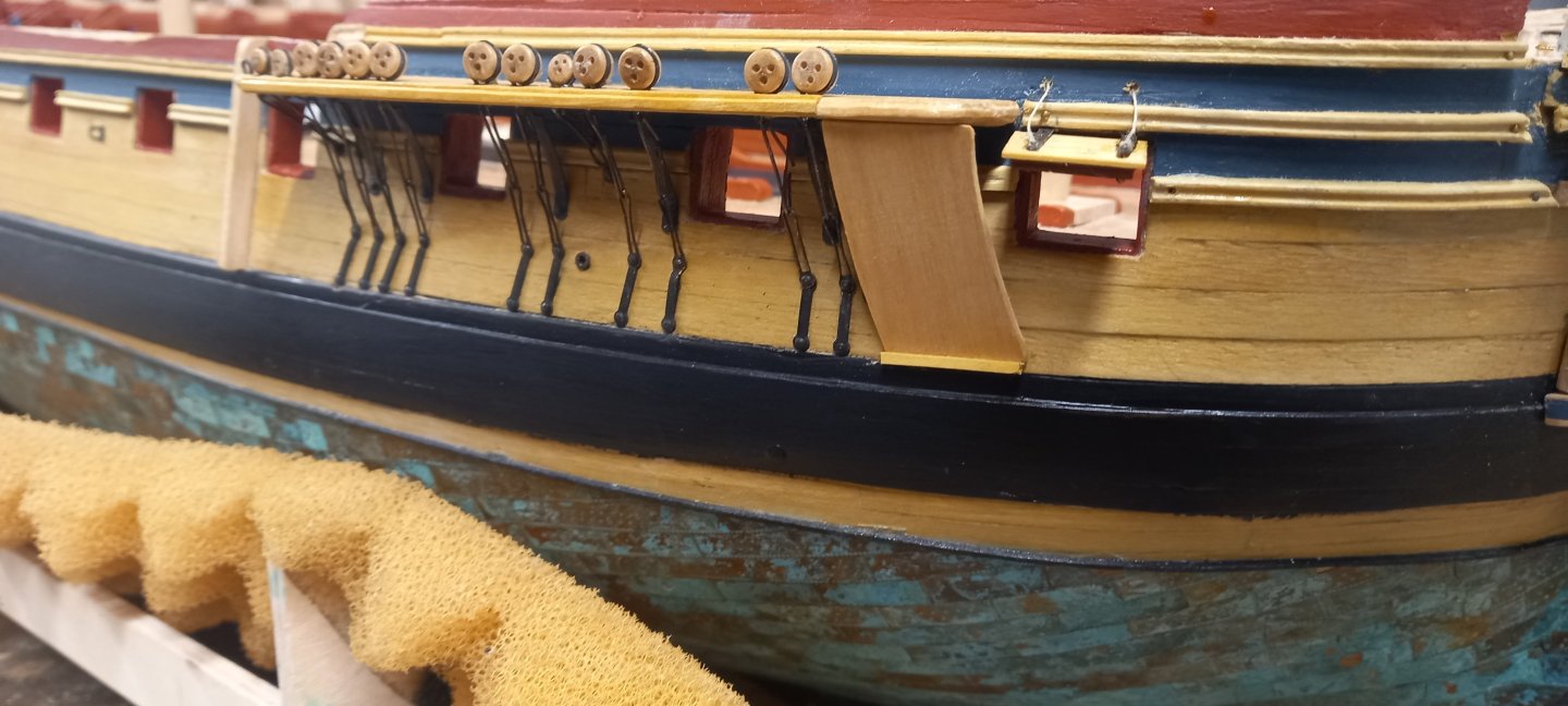
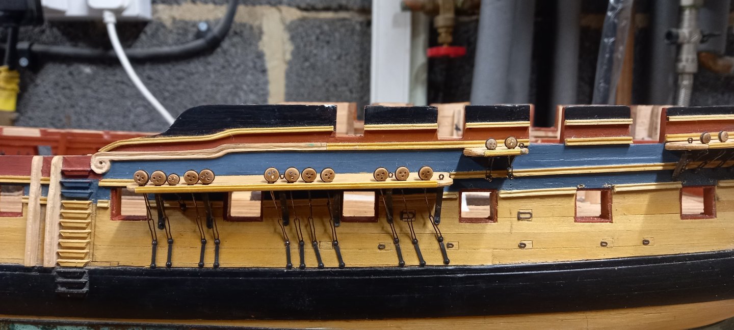
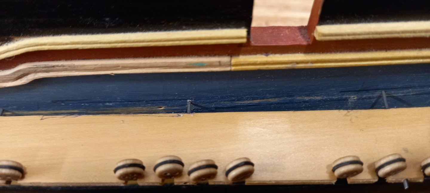
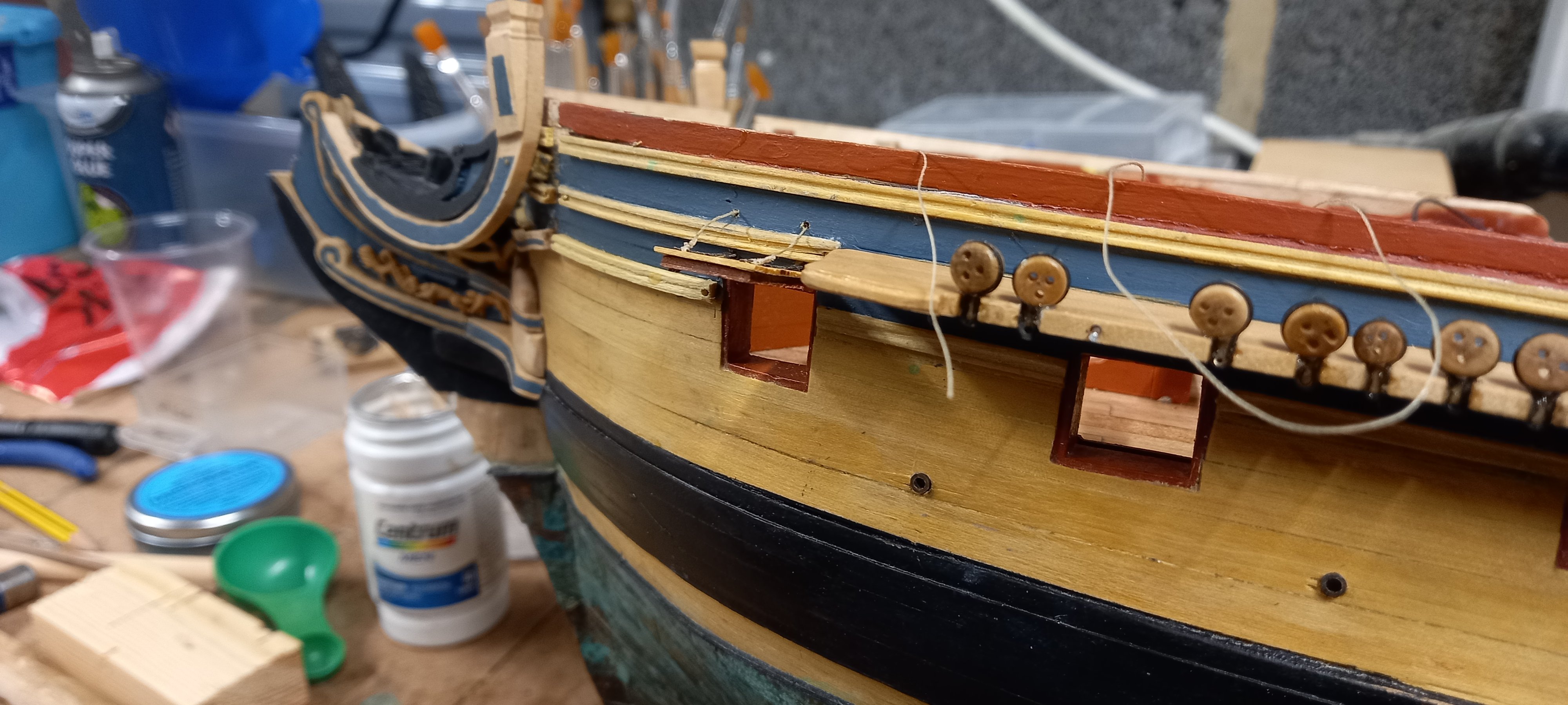
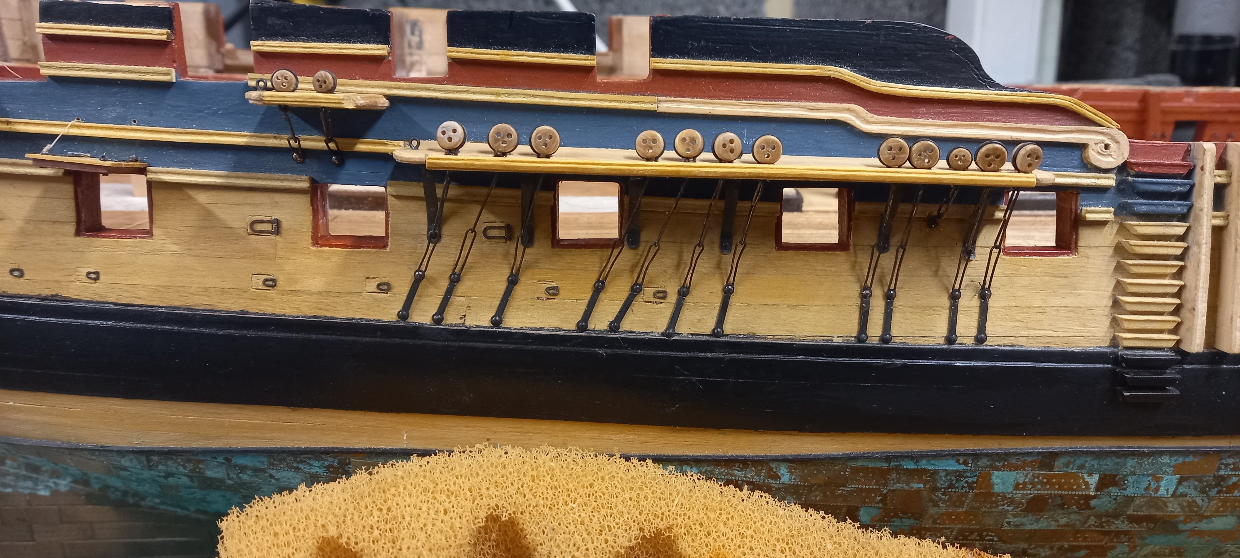
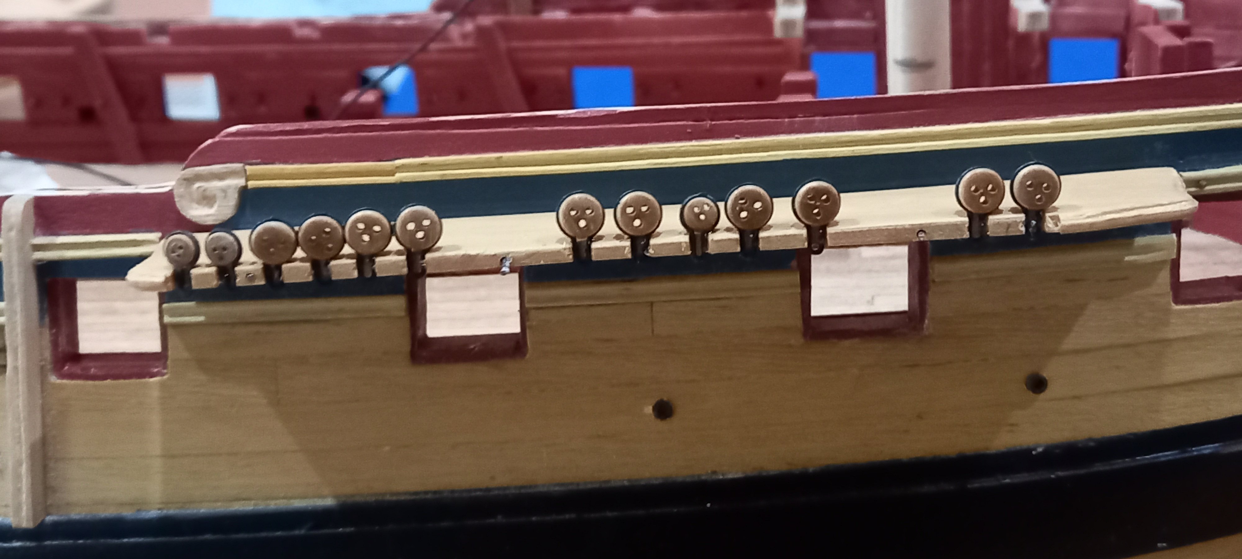
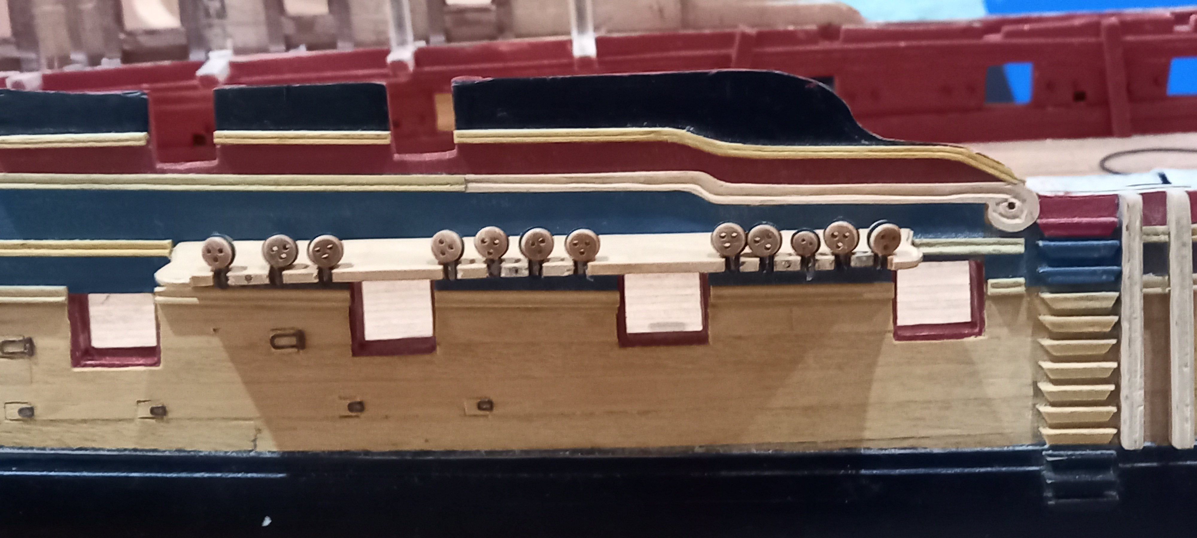
I thought this would be a good time to make the gun port lids and drill the holes for the ropes for opening them. I then attached the channel brackets after blackening them. I then attached the various preventer links just above the main wale as per the AOTS drawing and ensured they were in a straight line. It was therefore necessary to make the lower links at different lengths to suit and found this time consuming but hopefully was worthwhile. It was necessary to shorten the channel brackets for the Mizzen channels.

I also attached the stools using 0.8mm piano steel wire and super phatic glue.I also fitted the top and topgallant backstay stools and associated chain plates and links at the stage too.
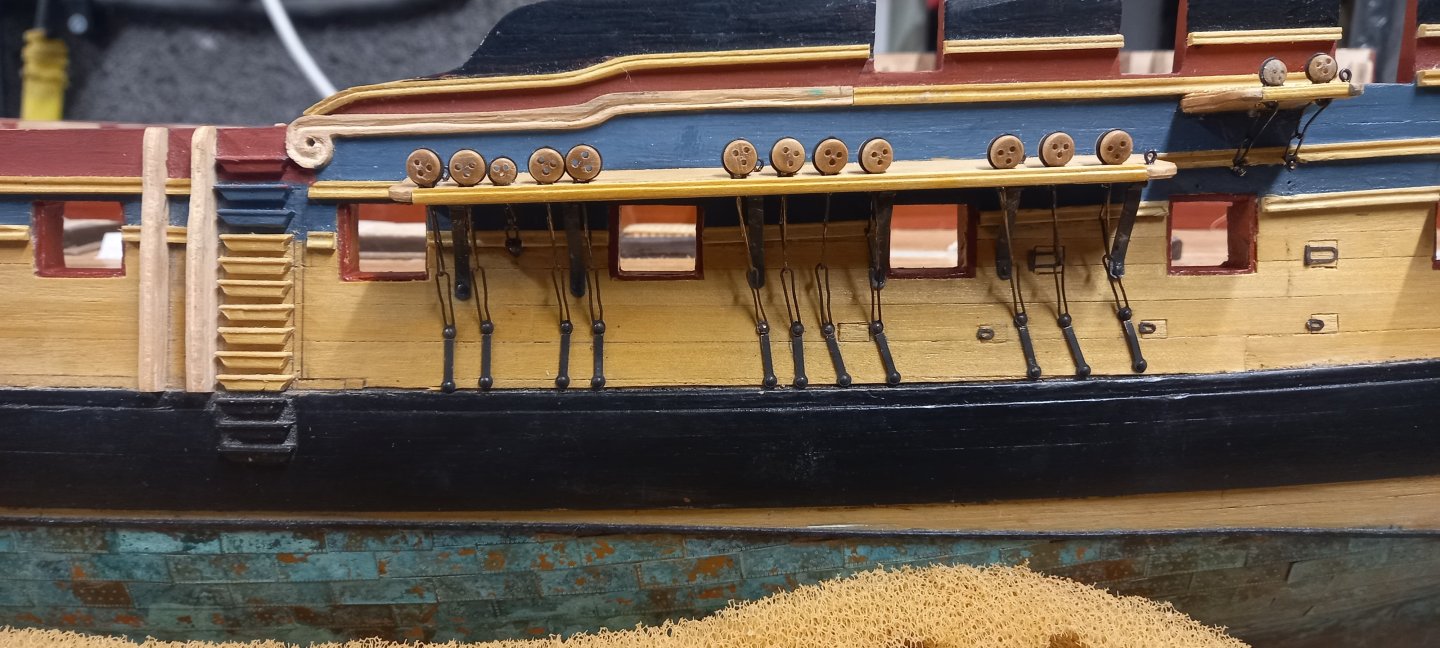
I also made up the Anchor boards from 1mm boxwood veneer rather than the supplied walnut ones and made up some boxwood rails using steel shapers to cover the the front of the channels and hide the deadeye strops.


- Thukydides, DavidEN, Ronald-V and 5 others
-
8
-
Some really nice clean and tidy work. How are you finding the build compaired to your other builds. Any anomalies with the kit parts etc. Good to see another Aggie, especially at 1:64
-
Fantastic looking boats David and well worth the time it has taken you to make them and I definitely liked your approach.
- DavidEN, Blue Ensign and shipman
-
2
-
1
-
12 hours ago, DavidEN said:
Hi Dave,
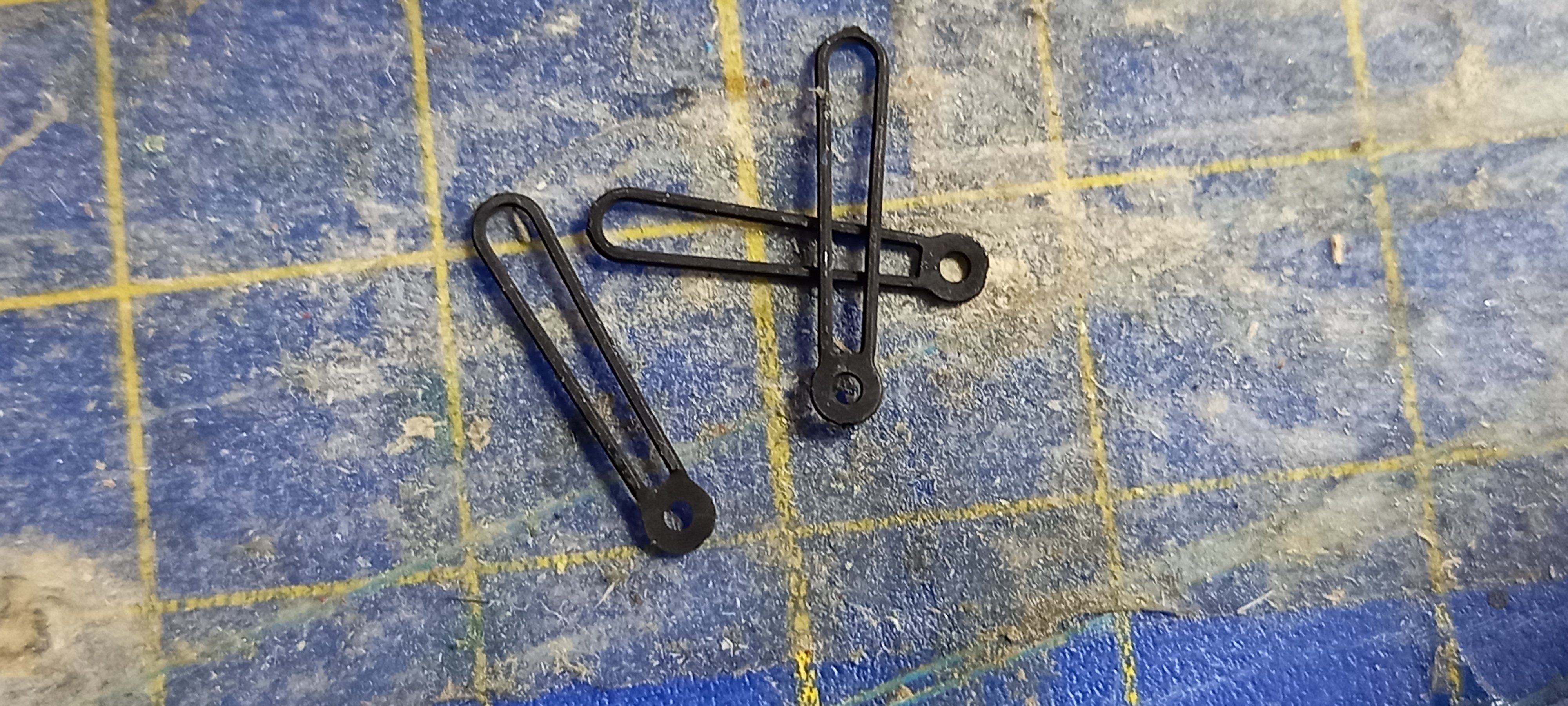
I also had the problem with the missing lower chain plate straps and spent some time making them myself. I subsequently discovered that Caldercraft had included the missing ones on the photo etch next to the ships wheel.
Regards,
David
Once again you have come to my rescue. You have probably saved me quite a few £££££. I also take my hat of to you sir for making these items as they do look a bit fiddly for my skill level.
After gluing in the deadeyes and their associated strops into the recesses I have noticed that the aft group of deadeyes on the foremast channels are shown on the NMM museum plans as having only 3 large deadeyes rather than depicted in the Caldercraft drawing which has 4 of these 5mm deadeyes . The AOTS Diana drawing also has 3. I have no idea why Caldercraft have this as different but wonder if this was changed at a later date and hence the extra two lower chain plate straps inside the steering wheel packet. Unfortuantey I just copied the Caldercraft channels for the number of recessess required and it would require me to make the forward channels again and feel it is too late for this as I do not have enough boxwood of this size in stock .I just wish I had at least stuck with the other drawings and not used the Caldercraft channels for guidence in this instance, although no doubt they have their reasons for doing it differently.Best regards Dave
-
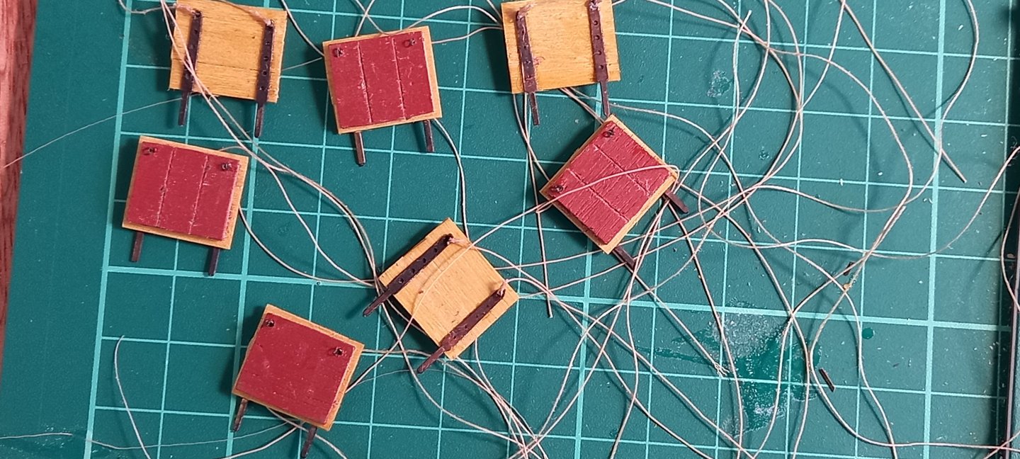
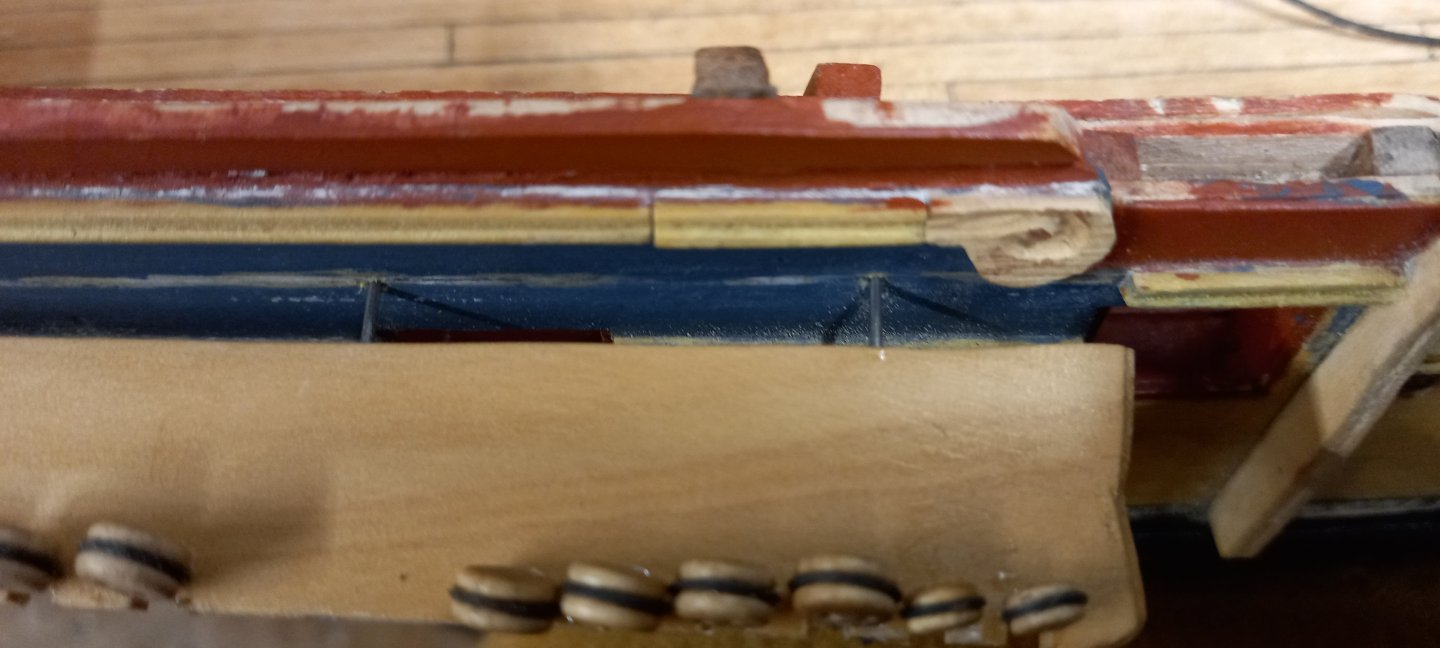
Continued with work on the the channels and blackened the many small chain plates ,links and preventer links.. After visiting my local modelling shop I noticed they supplied different diameters of piano wire. So I decided to use lengths of 0.8mm piano wire instead of brass for additional strength when securing the channels to the hull.
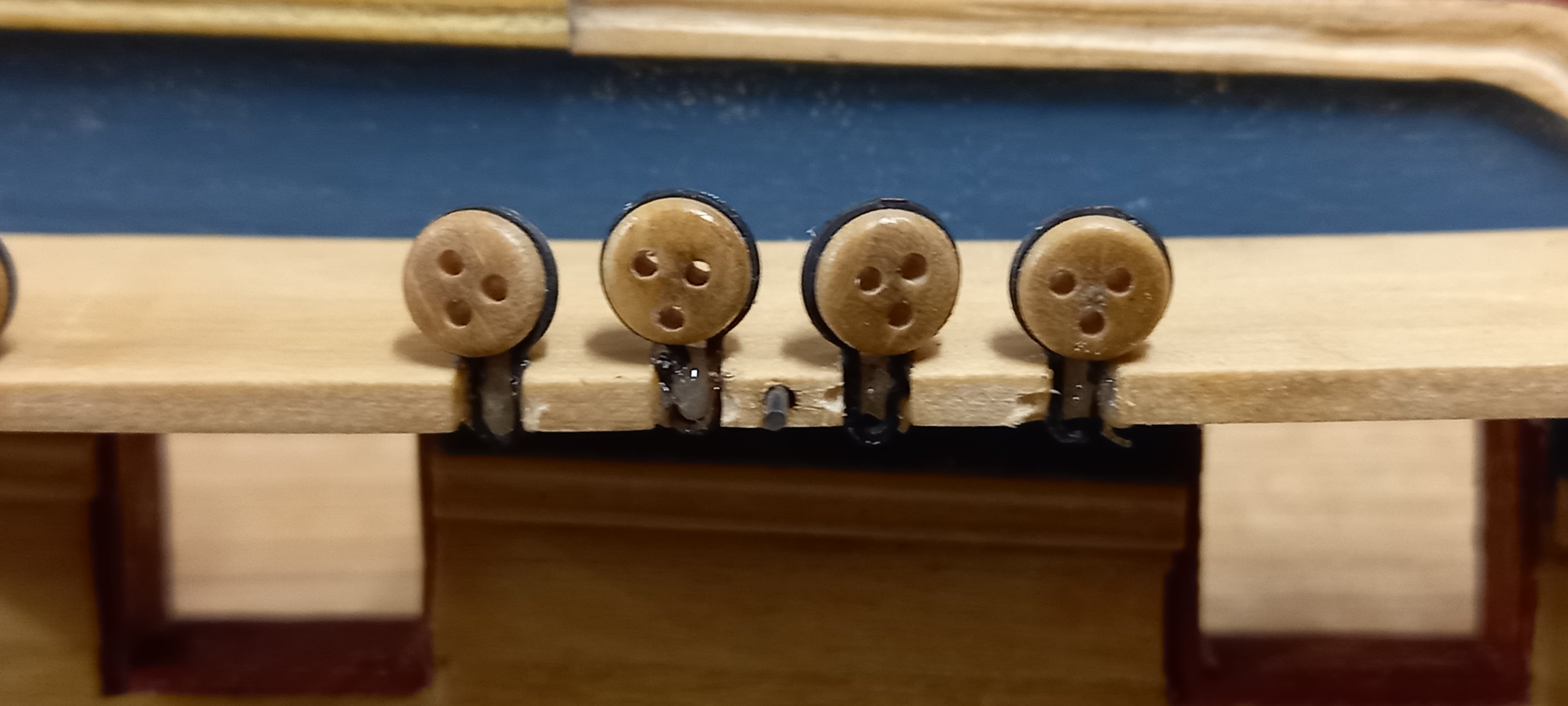
I have had difficulty with using the Caldercraft deadeye strops in the past so this time I glued them into the recesses using epoxy resin ,hoping this would make a much stronger job. I also made a couple of small tools using dowl and piano wire for turning the deadeyes. For the record I now wish I had used boxwood deadeyes instead of walnut especially the smaller 3.5mm size as these were of poor quality as a lot of the holes were spaced in the incorrect positions and don,t look to good. Unfortunately I have now glued these into position and I am unable to remove them without damaging the channels.The apoxy resin is super strong but I think the next time I will definitely not be using the Caldercraft walnut deadeyes and their strops.
Brass wire replaced with piano wire.
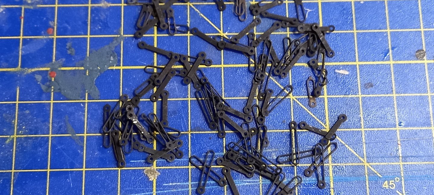
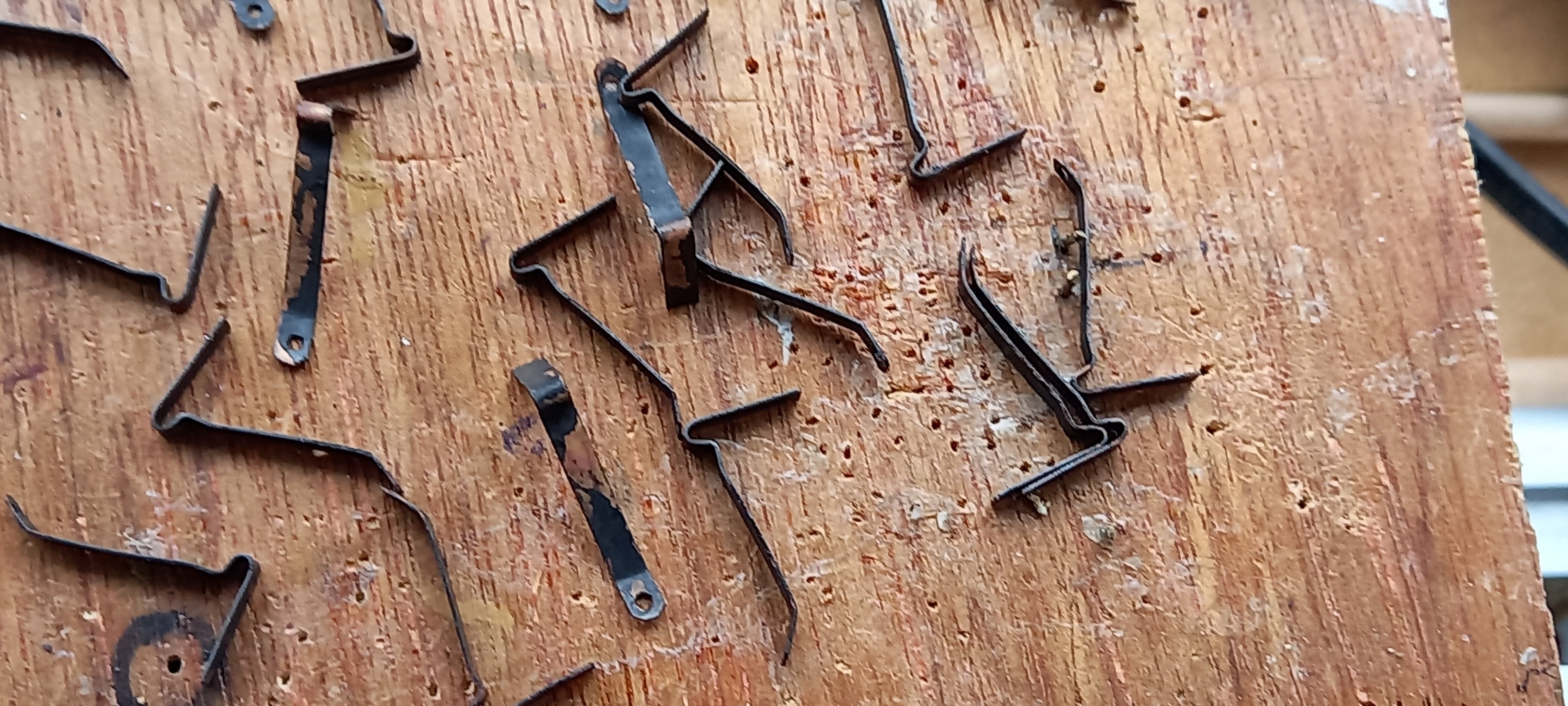
Another anomaly with the kit was the number of longer Lower chain plate links part no 259 for the 5mm deadeyes required is 42 ,whereas the number supplied was only 40. The number of preventer links supplied confirms this shortage, there being 42 of these. I wonder if anyone else has had this problem. So I need to get in touch with Caldercraft as I don,t think I can make these.
here is a sample of the missing lower chain plate strop part no 259. There might be a problem here as these are part of a brass photo sheet but still hoping Caldercraft can supply the missing two links.


- DavidEN, dunnock, Thukydides and 2 others
-
5


.jpg.1e73e6ed0a2b1576448dce234cf479fe.jpg)
.jpg.8ed6ac7a708e70aca2c2280cc1974460.jpg)
.jpg.f8febdb388709897ff115f5c327eed28.jpg)
.jpg.bbbaa2f2f2e64c53d64a329f698422ab.jpg)

.jpg.60b147ea1fe05c52f1b26e2e0208ad0b.jpg)


.jpg.f175a510f7245dab6c015c2f9341b9fe.jpg)
.jpg.6a33c3081e79ec1f8271238509fee17d.jpg)
.jpg.ad763f2b492d69c509d140aa83bb01c0.jpg)


.jpg.5c55a2694589324689668aa32b921fce.jpg)


HMS Diana 1794 by DaveBaxt - Caldercraft - 1:64
in - Kit build logs for subjects built from 1751 - 1800
Posted
Thank you Andrew.I have just taken a long break due to other commitments but hopefully it won't be too long before zi am back hard at it. Hope you and your family are well!