


BANYAN
-
Posts
5,964 -
Joined
-
Last visited
Content Type
Profiles
Forums
Gallery
Events
Everything posted by BANYAN
-
 Hi Karel and John. if you look at your earlier photo (post #59 second photo) commenting on the railing sizes etc. you can see the foot (well the flukes at least) of an anchor on deck. To me, those flukes look like those of a Trotman anchor (or possibly of a Porter anchor which was the forerunner to the Trotman). The crop of that photo (attached) certainly has the hallmarks of the early Trotman type anchor. cheers Pat
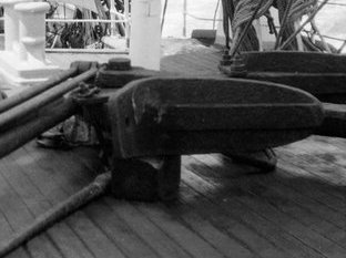
-
Hi Keith, I have been following along in the background and enjoying your journey with this one. Your build is coming along very nicely. If you will permit me another suggestion might be to use a section of clear plastic (shirt box or the light) for a section of the shed roof to allow visibility to your boiler? You could paint a little bit of the edges to give that ragged edge look a lot of illustrators use to imply a 'peeled away' section. cheers Pat
-
You're doing a grand job on this restoration John, looking good. cheers Pat
-
That's looking terrific Steven, a very nicely finished model (which has been well researched). cheers Pat
-
Hii Keith, following along with great interest. Could it possibly be a shore power/utilities connection point? However, those were usually on the deck/deckhouses but a possibility? cheers Pat
-
@rwiederrich That's some very nice work Rob, looking good indeed. @ClipperFan and Rich you are providing some very nice drawings/sketches. I am not commenting much as you guys have this well in hand, but I had to acknowledge the enjoyment I am getting following along. cheers Pat
-
I look forward to following this build (as I have your previous builds) Eberhard. You pick some very interesting subjects for your models. cheers Pat
-
Another unique and wonderfully presented SIB Glen, you've earned your tot with this one. I have enjoyed the journey. cheers Pat
- 235 replies
-
- 5
-

-

-
- Banshee II
- Bottle
- (and 1 more)
-
That's looking great Glen, and you have created a great little stage for those pesky penguins to perform on Seriously, I very much like the combination of the Texas backdrop and the wharf, a unique and very effective concept. cheers Pat
- 235 replies
-
- 7
-
-

-
- Banshee II
- Bottle
- (and 1 more)
-
Wow Keith, that hull looks magnificent - those photos really show off the sleek profile and beautiful flow of her lines. While the cat's away, the mice will play - my Admiral will have blown a safety valve. Great advice on the use of the round sanding sticks (pencils) to true the shape of the portholes. cheers Pat
-
Working with blackend brass.
BANYAN replied to SiriusVoyager's topic in Metal Work, Soldering and Metal Fittings
When I did my Endeavour I pre-blackened the deadeye straps and chain plates separately (using Birchwood Casey Gun Black). I then installed the deadeyes and used a holding jig (made from scrap wood) to hold the straps and chain plates then soldered them together. The small area around the solder point (well away from the deadeyes) could then be retreated after cleaning. As this method did not require any twisting etc of the wire I did not have to worry about that particular issue. The deadeye strips had the loop with two legs that formed a short vertical strap that was then attached to the chain plates - not sure if your deadeye strips are of a similar design? A similar approach may work for you? Unfortunately much of the related photos and discussion around this part of my build were lost in the 'Great crash of MSW 1' so unable to post photos. Also, I use resistance soldering which less aggressive than using a pencil or other flame torch. A electric soldering wand will keep the heat down especially if it is a variable power type. cheers pat -
Hi Greg, I have been following along without commenting but have to now That is a very nicely finished diorama, even if based on a small easy to assemble kit. The overall finish is superb with all detail nicely shown. cheers Pat
- 12 replies
-
- 3
-
-
- Kriegsfischkutter
- ICM
- (and 2 more)
-
Bravo Glen, those front piles look so authentic and scale correct. Looking good mate. cheers Pat
- 235 replies
-
- 6
-
-
-
- Banshee II
- Bottle
- (and 1 more)
-
Thanks Glen, a great relaxing holiday and just what I needed. I hope you don't mind but ... Snap! I think the first photo following is of the same point of land (that you show in your posted piccy) taken from a slightly different shooting point, and a sunset to boot. Nothing special, just taken from my phone camera. cheers Pat


- 235 replies
-
- 6
-

-
-
- Banshee II
- Bottle
- (and 1 more)
-
Hi all, I found the discussion I referred to. It is in a book titled 'Ship Joinery' by S.G. Duckworth (1923) - see chapter X (page 118). PDF copies can be found online. While it is not truly describing vessels of the 19th century, I think the essentials of the joinery practices will not have changed much, if at all. In this he states: Ladders are made in various sizes, the spread being usually from 1 ft. 6 in. to 2 ft. 6 in.; the rise to be comfortable should not be greater than 9 in.; and the slope should be such that the angle between the ladder side and a plumb-line will not be less than 37°. Later, starting at page 126, he discusses stairs which is far to large a section to paraphrase here. Essentially he writes that the 'straight' stairs' typically had a rise of 7" and a going (horizontal distance between the faces of two risers) as 9". He also provides excellent drawings of the style and parts of the staircases and associated companionways. I hope this helps cheers Pat
-
What a collaboration of minds this project is! I am convinced you guys will arrive at the most probable hull form and equipment fit with this sort of preparation and contributions. @druxey and @@ClipperFan, I am not 100% sure of this, but I seem to recall a discussion on the subject of stairs and ladders in one of the pdf copies of wood ship construction or wood joinery (ship related) books written about this era. As soon as I have caught up on the neglected chores etc. resulting from my trip I will have a look and see if I can find it. cheers Pat
-
That looks pretty sweet from my vantage also Steven. cheers Pat
- 110 replies
-
- 4
-
-
-
- Paddlewheeler
- Ballarat
- (and 3 more)
-
Hi Rob, I go away for a couple of week's holiday and return to find another wonderful clipper project on the go. Sorry to latch onto the coat tails of the project so far along, but it looks like this will be another entertaining log and great build. I hope there is still room to jostle into the peanut gallery? cheers Pat
-
Just back from my holiday in Norfolk Island Glen and happy to see the excellent work you have done in progressing your latest SIB. Glad to see you could also find some useful work for those dastardly penguins - about time they earned their keep cheers Pat
- 235 replies
-
- 7
-
-
-
- Banshee II
- Bottle
- (and 1 more)
-
Just back from my holiday to Norfolk Island Keith and absolutely delighted to catch-up with your pile driver log. Some great progress and I look forward to seeing more. cheers Pat
-
This will test your skills in a whole lot of other ways Keith. Looking forward to seeing this all come together. cheers Pat
-
Better watch that one at the bottle's mouth Glen, looks like it has its eye on the target. cheers Pat
- 235 replies
-
- 4
-
-
-
- Banshee II
- Bottle
- (and 1 more)

