BANYAN
-
Posts
5,961 -
Joined
-
Last visited
Content Type
Profiles
Forums
Gallery
Events
Everything posted by BANYAN
-
 Glad to hear you had a great trip Glen, even if you put on a couple of extra pounds (sounds so delicious - envious). Looking forward to seeing how you put all those parts together in that bottle; you're making great progress mate. cheers Pat
- 235 replies
-
- 6
-

-

-
- Banshee II
- Bottle
- (and 1 more)
-
I thought they were the only type of jigs to build John Noice work Steven. cheers Pat
- 110 replies
-
- 5
-
-

-
- Paddlewheeler
- Ballarat
- (and 3 more)
-
Ditto Bedford, such an obvious technique yet most of us mere mortals never think of such ideas. cheers Pat
-
Short answer I think is that it depends on the era and nationality of the vessel. In some ships some of the ratlines started on the leading shroud, but others on the second, and some terminated on different shrouds also, others were staggered in a specific pattern. For English ships, Lees is a good references. For French ships I would suggest Boudriot is a good reference as he is very familiar with French ships. Some research will be necessary to determine what is right for the ship you are modelling for 1577. Some more knowledgeable people here may be able to assist further if you could provide the name/nationality and rate of the vessel. cheers Pat
-
Nice 'bodging' Eberhard, the crew are looking good. Your steady hands have come to the fore with some really well defined fine detail showing. cheers pat
-
Great to see another post Bruce and good luck for a hassle-free move. Look forward to seeing your build on the workbench again. cheers Pat
-
18th Century Iron nails
BANYAN replied to tmj's topic in Building, Framing, Planking and plating a ships hull and deck
News to me but an interesting idea/practice. I am researching in the 19th century and have not yet come across this, but I have not really been looking. If I find anything I will get back to you. cheers pat -
Great to hear all is good and see you posting again Michael; I have been missing the Cutter updates. However, life decides our priorities so will wait patiently. cheers Pat
-
That's a lot of detail in a very small space Glen. It's inspiring watching you sort through all of the sequencing issues to get it right. cheers Pat
- 235 replies
-
- 5
-
-
-
- Banshee II
- Bottle
- (and 1 more)
-
Hi Roger. I have some broaches (not just triangular as some have five sides) but they are all tapered. Does your set have a constant size so that they can also act a reamers to achieve a very accurate size? cheers Pat
-
Hi John, sorry had missed this log. Looks like an interesting project on a model of a very interesting vessel. Good luck with it, will enjoy watching your progress. cheers Pat
-
Congratulations again Rob, your excellent model is a very realistic representation of Mackay's majestic vessel. The level of detail make it difficult to discern between the real and the model sometimes. cheers Pat
- 3,560 replies
-
- 1
-
-
- clipper
- hull model
- (and 2 more)
-
So fighting fire with fire so to speak Glen? Let's hope it never gets to that point. cheers Pat
- 235 replies
-
- 5
-
-
-
- Banshee II
- Bottle
- (and 1 more)
-
HMCSS Victoria 1855 by BANYAN - 1:72
BANYAN replied to BANYAN's topic in - Build logs for subjects built 1851 - 1900
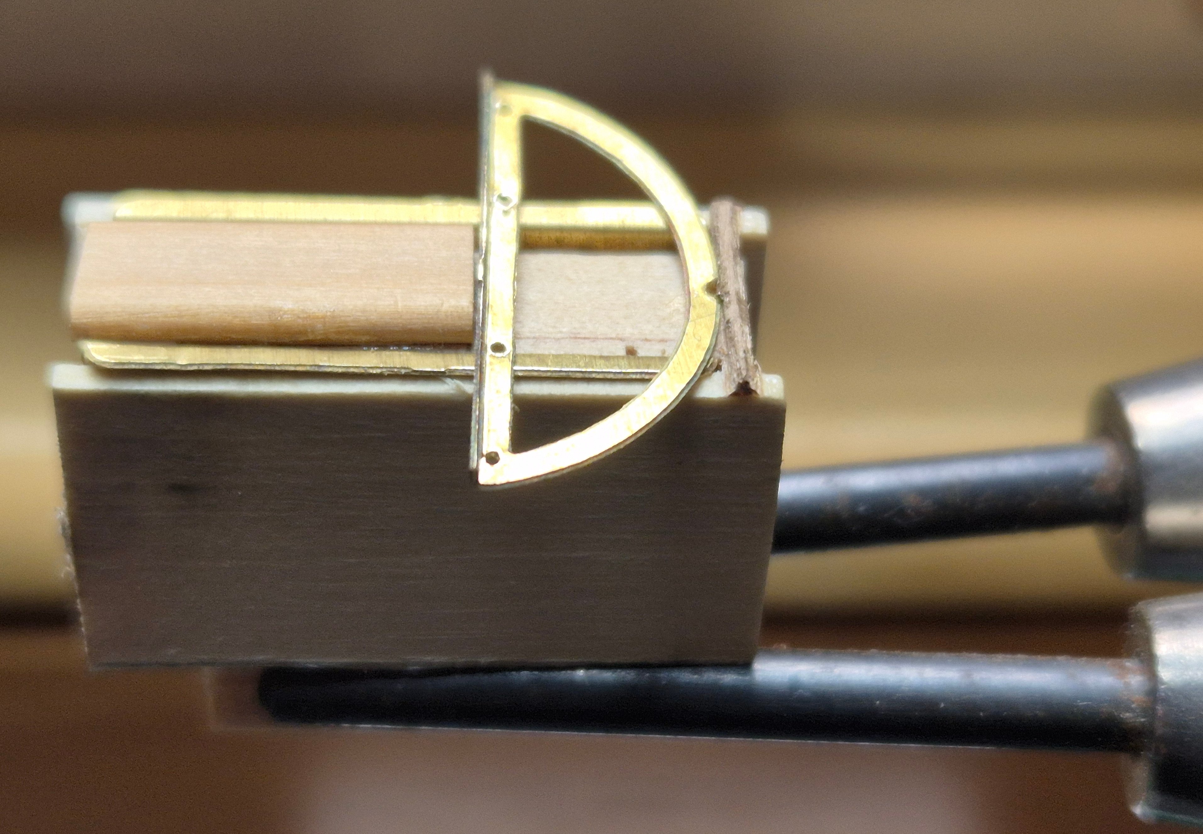
Thanks @wefalck, @Glen McGuire and @Jim Lad, appreciate the feed back. Eberhard, I did have the same idea but using the actual mast. That is pin and glue the cheeks in place first, but with the very small items I was concerned about keeping the tops of the trestletrees parallel and exactly aligned. This jig at least keeps one of these variables (spacing) under control, and with a bit of care should be able to control the parallel aspect. The central spacer is exactly the width of the masthead BUT, there is a tiny bit of 'slop' in the hound/cheek slots, so I may have to seriously reconsider your idea. Glen one of the three key 'bodging' tools - duct tape, 16 gauge fencing wire and a big hammer. I may have to resort to duct tape if all else fails - then again I could get those pesky penguins to hold it in place if Keith will spare a couple - yeah I know 🤐 John, if I hadn't already made the masts that could have been an serious option to consider; thanks for the idea. cheers Pat- 1,018 replies
-
- 5
-
-
-
- gun dispatch vessel
- victoria
- (and 2 more)
-
HMCSS Victoria 1855 by BANYAN - 1:72
BANYAN replied to BANYAN's topic in - Build logs for subjects built 1851 - 1900
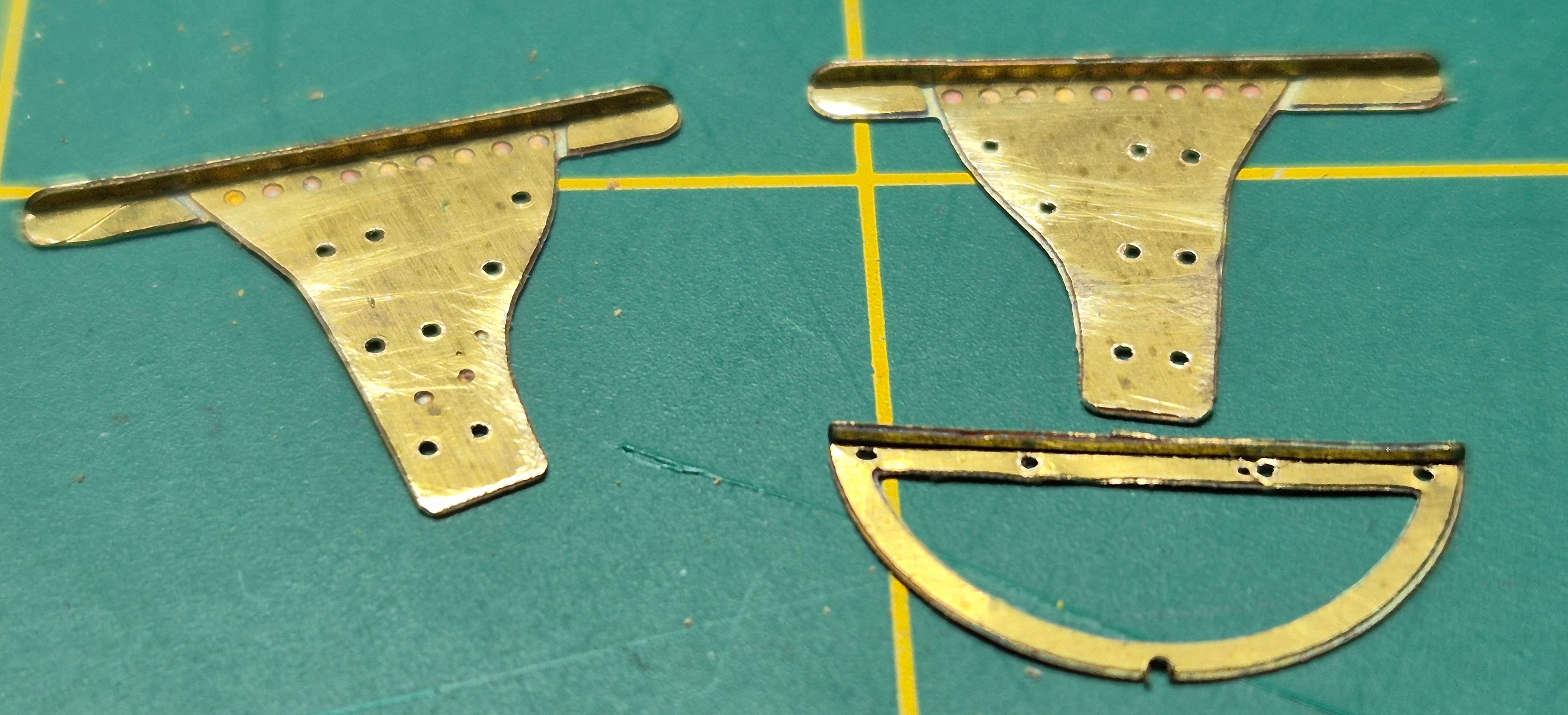
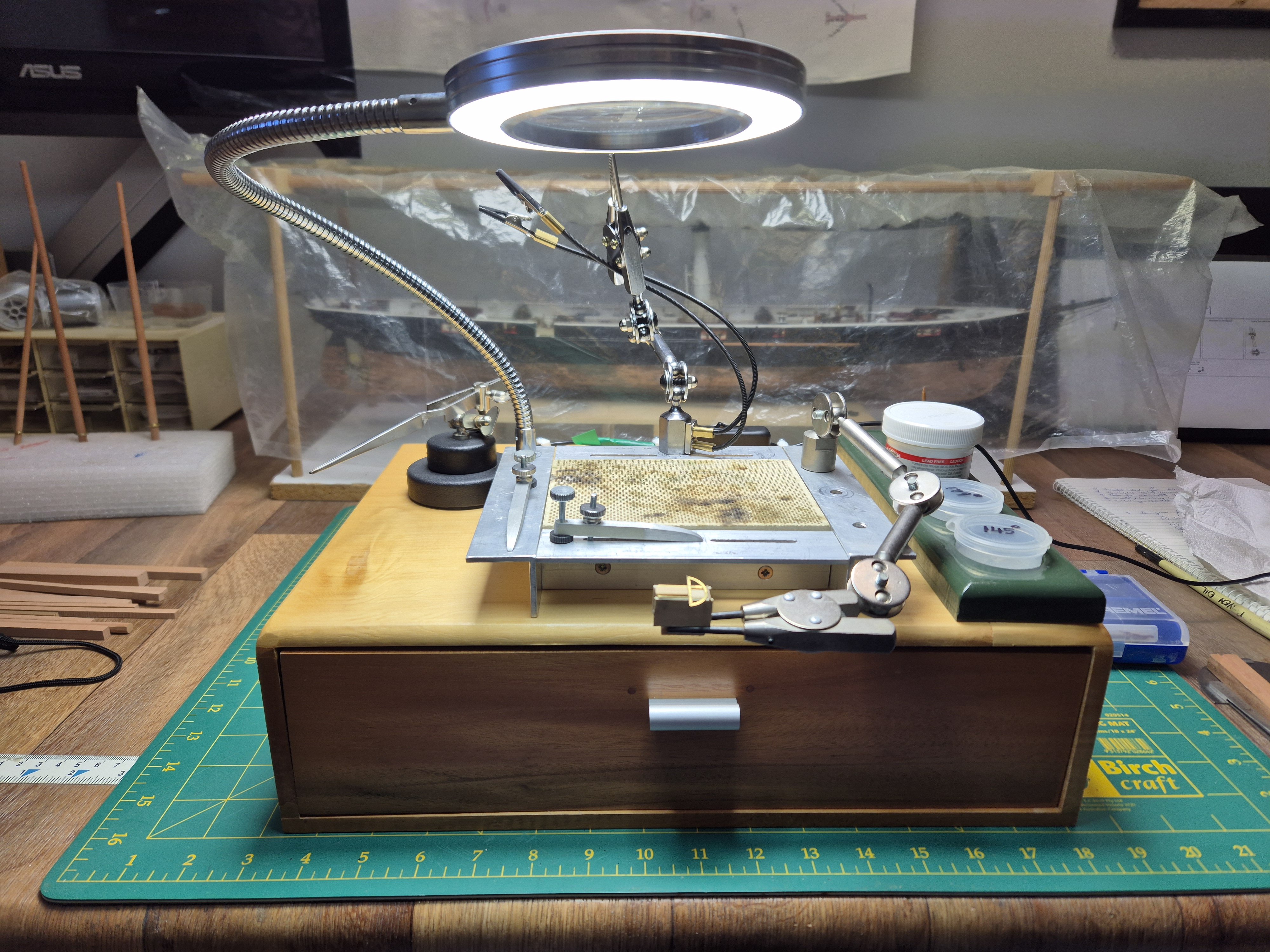
A little more to report. I have been experimenting to determine the best jig to solder these tiny pieces together. The following show a very rough version of what I think I will try. The principle seems OK but the jig needs a little 'finagling' and then to be remade in a denser wood before I dare attempt any soldering. The brass PE parts have had holes drilled to accept the through mast bolts, but as is obvious, they need a lot more clean-up yet I am open to ideas to modify this jig before committing so please have at it. The general idea is create 2 slots held in place at the width of the masthead flats. The rim, which has yet to have the fore part of the rim soldered to it (see much earlier posts on this) then sits on top of them, and, after centering it, will somehow be held in place so that it does not move - I am still trying to sort that bit. The final shot shows how it will be held in my soldering station when I get around to soldering. Then I have to think about how to put on the crosstrees with the iron rod (brass) stays pre-attached to the cross trees and the futtock band... but, that is a problem for 'future Pat' as the saying goes. cheers Pat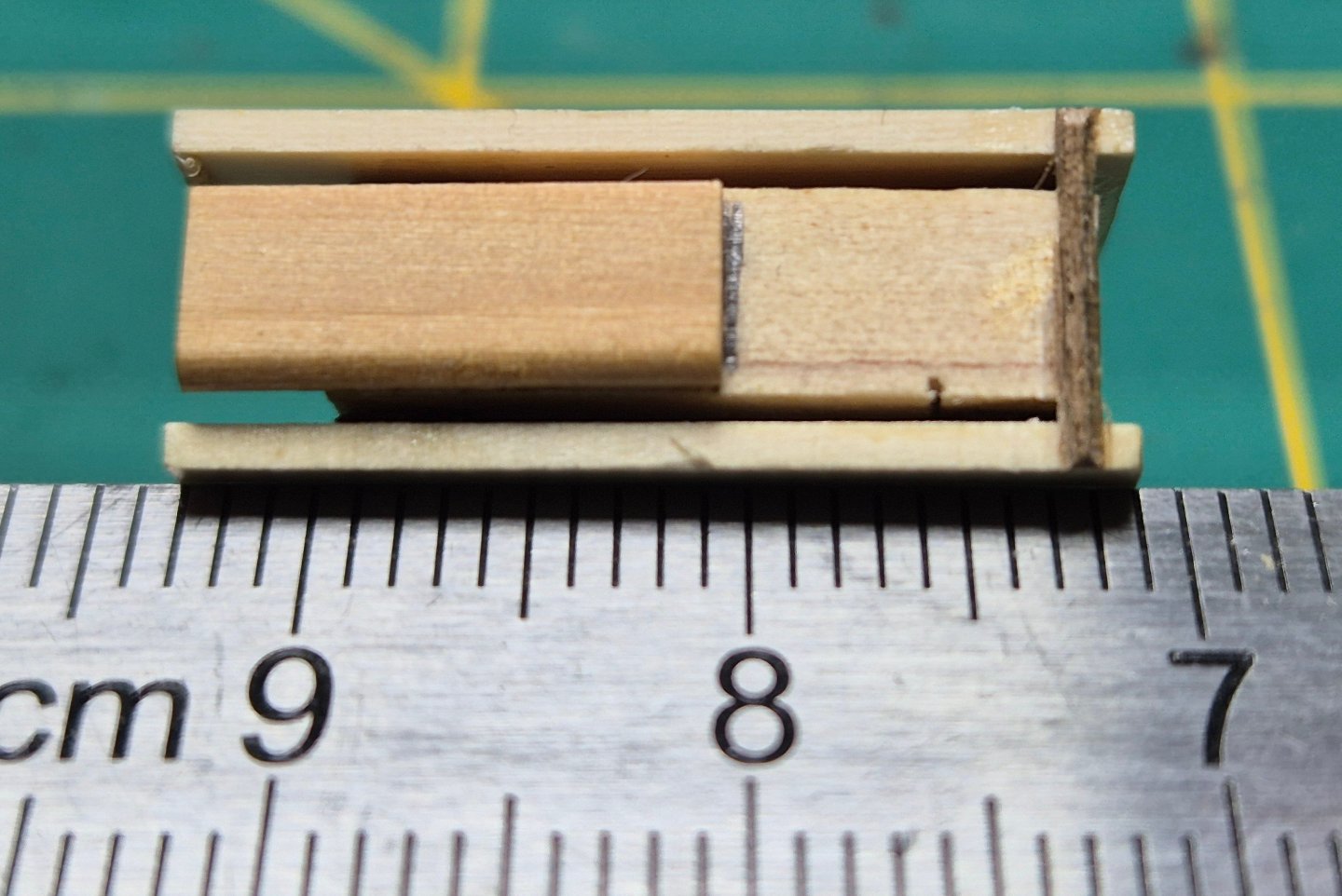


- 1,018 replies
-
- 15
-
-
- gun dispatch vessel
- victoria
- (and 2 more)
-
A well dressed (painted) crew you have there Eberhard. You must still have very steady hands to achieve this level (quality) of work. cheers Pat
-
Keith would probably suggest a Penguin sitting on the lip of the funnel steaming its 'hot dog' in the waste steam cheers pat
- 235 replies
-
- 6
-
-
-
- Banshee II
- Bottle
- (and 1 more)
-
She's coming on splendidly Ian, looking great! Some very neat lashing there, bodes well for your rigging to which I am ;looking forward to seeing. cheers Pat
- 536 replies
-
- 4
-
-
-
- Quadrireme
- radio
- (and 1 more)
-
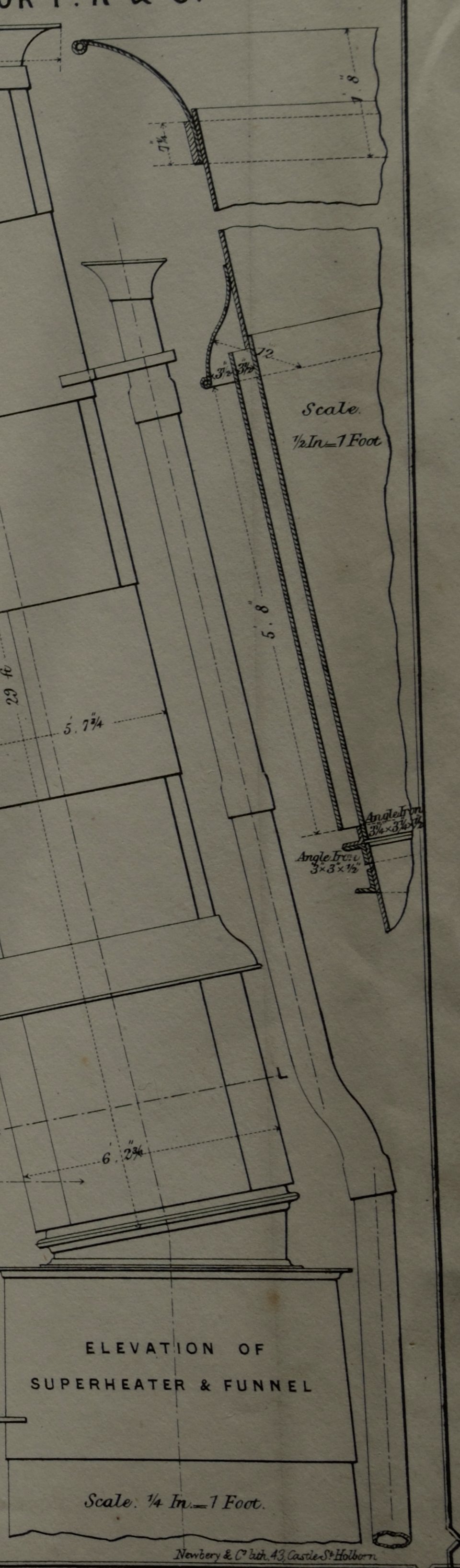
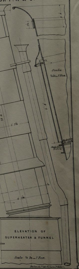
Hi Glen, great progress and a joy to follow along mate. If not too late, what you describe as a 'spine' to the rear of the smoke stack (funnel) is actually a separate pipe with a slightly flared top which was a steam release pipe associated with the safety valve on the boilers. See attached. At your scale though this would be difficult to create (although some brass wire/rod may do the job), and as I said earlier, maybe a little late to change even if you wanted to. cheers Pat
- 235 replies
-
- 5
-
-
- Banshee II
- Bottle
- (and 1 more)
-
Hi Rob, are you hinting this is your last model? cheers Pat
-
Thanks for the feedback Glen. I find the way you sort out these 'puzzles' is of great interest to me (being a non-SIB builder). Have fun reading the book, looks interesting. cheers Pat
- 235 replies
-
- 5
-
-
-
- Banshee II
- Bottle
- (and 1 more)
-
Those images prove the high degree of your excellent research and skills Rob. Hard to tell/find any differences. cheers Pat
- 3,560 replies
-
- 2
-
-
- clipper
- hull model
- (and 2 more)
-
Stunning progress Glen, she is looking great. Hopefully you will be able to maneuver the assembly into position without much of a problem. I am assuming the fore-funnel will not be placed until then? Cheers Pat
- 235 replies
-
- 4
-
-
- Banshee II
- Bottle
- (and 1 more)