
HOLIDAY DONATION DRIVE - SUPPORT MSW - DO YOUR PART TO KEEP THIS GREAT FORUM GOING! (Only 72 donations so far out of 49,000 members - Can we at least get 100? C'mon guys!)
×


BANYAN
-
Posts
5,946 -
Joined
-
Last visited
Content Type
Profiles
Forums
Gallery
Events
Everything posted by BANYAN
-
 Another interesting backdrop Glen, should look great! cheers Pat
- 235 replies
-
- 5
-

-

-
- Banshee II
- Bottle
- (and 1 more)
-
Those fantail decorations came up a treat Ian, nice bright opaque colour; very nicely done. cheers Pat
- 536 replies
-
- 4
-
-
-
- Quadrireme
- radio
- (and 1 more)
-
Hi Glen, WRT CNC - Computer Numerical Control which is a machining method for mills etc using a specialized computer code to control the path of the cutter. I thought this method may have been a walk in the park for you Now for a tot of Bundy Rum (yummy!) cheers Pat
- 235 replies
-
- 5
-

-
-
- Banshee II
- Bottle
- (and 1 more)
-
Oh please do this one Glen, I hear you are real dab hand with CNC Seriously though there are plenty of approaches. I visited a motor museum in the Melbourne (Australia) area a while ago and was pleased to find some 'folk art' style model ships a local had made using drink cans (and another excuse to buy some additional beverages - as stock for the build of course). I think he may have formed the hulls from a wood plug then cut individual (large) plates which he then used to build up the hull and superstructure. Whichever way you go I am sure it will be another masterpiece. cheers Pat
- 235 replies
-
- 4
-
-
- Banshee II
- Bottle
- (and 1 more)
-
Those planks are looking great Keith and really start to emphasize the beautiful hull form of this vessel. Enjoying watching your progress. cheers Pat
-
Nice find Keith, I'll have to look into these and see if they do 1:72 (or something close) as well. Looking forward to seeing these in-situ as you are doing a great paint job. Glad to hear Maggie continues to improve mate. cheers Pat
-
Great project Glen, ships from this period are of particular interest to me, so I am really interested to see what you come up with this time. cheers Pat
- 235 replies
-
- 5
-
-
-
- Banshee II
- Bottle
- (and 1 more)
-
Hi Steven, a couple of thoughts. If t is not too late, I would avoid a fret saw as the blade is very flexible and may wander while cutting? I would look at a high tooth count fine stiff backed saw such as a small 'gentleman's' dovetail saw. I bought one years ago and it has proven very reliable for this purpose. The following is a Zona version (I think Hobby Tools Australia have this brand). The second is more of an alternative idea for your wheel spokes. - that is unless the real wheel has straight spokes anyway. I have had previous success using tooth picks - the ones with the fancy ends like the cocktail ones. I simply cut off the outer nub and round the new end a bit, then cut to length. They look reasonably good when stained. Your current one looks good, simply offering an alternative for future versions if interested. These ones are available from Woolworths. cheers Pat
- 110 replies
-
- 7
-
-
- Paddlewheeler
- Ballarat
- (and 3 more)
-
Enjoy the build Grant and a very happy birthday. Your sister is quite talented, a very nice painting. Will you paint this one in the revised colour scheme the actual ship is now/will be sporting? cheers Pat
-
A great (and nice looking) little project Steven, enjoyed the catch-up on your log. If doing multiples 3D printing some of the items such as the chairs, gates etc may help and be a lot cheaper/easier when considering the time you would spend if making them? then again if just providing the stock the cost would not be a concern but may put some budding modellers off? A great idea and what a great way to preserve some local history, I doff my hat. cheers Pat
- 110 replies
-
- 2
-
-
- Paddlewheeler
- Ballarat
- (and 3 more)
-
Love the colour of those planks Keith. The planks are sitting really nicely. cheers Pat
-
Great to see you persevering Mark. cheers Pat
- 11 replies
-
- 4
-
-
- half hull
- half hull planking project
- (and 1 more)
-
This will be one very finely lined model Keith; your preparation, as with your work, is simply outstanding. cheers Pat
-
There I go and not pay close attention to the forum and you sneak another wonderful build under my nose - how dare you! I don't know how I missed the log. At least it gave me some interesting reading when I found it today (only a month late but I'll put that down to encroaching 'old fella' symptoms). Great to see that you were able to satisfy all those 'stalkers and their penguins' in this build log . Again you impress with your dioramas providing a very interesting setting and nicely presented SIB. You should create a 'coffee table' style book of your work mate, it will hold up to any scrutiny. cheers Pat
- 109 replies
-
- 9
-
-
-
- Ghost Ship
- Jenny
- (and 2 more)
-
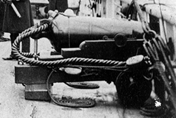
Hi Bob, agree your reasoning WRT using such coils. These coils may have been a bit more commonly used than perhaps thought. Further to Bob's comments, even in this day and age (well when I was in the service at least) where synthetic cordage is commonly used (and more prone to the effects of UV), these decorative coils were in common use for rope whenever the ship was in harbour/at the buoy or at anchor. When underway 'proper' working coils were always used. These coils are also evident in images of HMCSS Victoria (1855). It appears this may have been the general practice in RN ships (or military type ships) back then also, as can be seen in the following photograph (c.1858) of the gun tackle working parts being cheesed (or more correctly - Flemish coiled). The vessel was in harbour (moored) at the time. However, I must offer a point of difference in opinion WRT to how they were unwound. When reforming the coils, or taking the coil in hand, we would 'unwind' it from out to in by grasping the rope/line near the block or securing device, then walking the line out. This was the opposite to the way it was made up, which minimised the risk or tendency of the rope to kink, and allowed the rope to unwind with its lay. That said, other Services/ships may have done it differently. cheers Pat
-
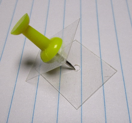
Hi Vossey, I will try to describe the technique I use for 'cheesing' the tail ends of tackles. Not my original idea, but it works well for me. First soak your rope/thread, cut to an appropriate size (if doing separate) in a diluted solution of PVS/water ( I use about a 60 water/40 PVA). If using the actual tail end of the tackle, this still works but just soak the required length of the tail (working end of the falls) I use two small squares (or round) of clear plastic (from shirt boxes or the like). I punch a pin (usually a tack with raised plastic head) through both (See Photo). Separate the two leaving the upper plastic square/round on the pin, and put the outer/tail end of the rope/thread through the centre hole of the bottom square with about 1 to 2mm protruding to the bottom side. Put the pin back into this such that it holds the end and makes a sandwich with the thread between both plastic squares. Now rotate either the assembly or wind the thread around the centre pin to start making a flat cheesed coil to the desired diameter. Allow the finished coil to dry before removing; the plastic does not let them stick too much but still take some care when separating the coil from the plastic. These 'jigs' are so easy and cheap to make you can dispose and remake as required, especially when the centre holes become too large from wear/use. Just one way to do it. cheers Pat
-
Great way to rekindle those memories Mark; good luck with this project. cheers Pat
- 11 replies
-
- 3
-
-
- half hull
- half hull planking project
- (and 1 more)
-
What a great result Eberhard; thanks for stepping us through the process. It looks very effective/realistic, especially at that scale. cheers Pat
-
A stunning build Richard; an exemplar of how to build such a model. I have very much enjoyed this build log so far. cheers Pat
-
You continue to show us just what is possible with your metal smithing Keith; impressive results. cheers Pat
-
That is some 'plodding along' Ian, looks great. cheers Pat
- 536 replies
-
- 4
-
-
-
- Quadrireme
- radio
- (and 1 more)
-
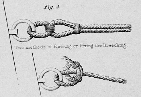
Agree, the following is from Capt. Boxer's (RN) 'Diagrams of Guns' (1853) which still shows the use of bending the breeching rope to rings in the mid-19th century. cheers Pat
-
Great to see this update Jason; your build continues to impress. cheers Pat
-
Great diorama Greg; have to agree that wake looks really convincing. cheers Pat
- 47 replies
-
- 1
-
-
- Zumwalt
- Snowman Model
- (and 2 more)