


Gabek
-
Posts
278 -
Joined
-
Last visited
Content Type
Profiles
Forums
Gallery
Events
Posts posted by Gabek
-
-
Beautiful work, JJ! A masterpiece.
Clear skies and sharp tools,
Gabe
-
Well done and congratulations on your first build! Can’t wait to see what’s next.
Clear skies and sharp tools!
- Gabe
-
This is awesome, Scrubby! I was about to sit down and draw one up for myself. I think I may try to print the metal frame and leave it open - then use something like Testor's window maker cement to create the glass portions. Thanks for offering the .stl file. I'll keep you posted on my progress.
Clear skies!
Gabe
-
Welcome aboard, Scott!
You are definitely in the right place.
I, too, am playing with 3D printing - A great new vista for modellers.
Looking forward to following your build logs.From the heart of Canada - Winnipeg 🇨🇦.
Clear skies,
Gabe
- Keith Black, Knocklouder, Dave_E and 2 others
-
 5
5
-
Pandora’s Box
What have I gotten myself into?!
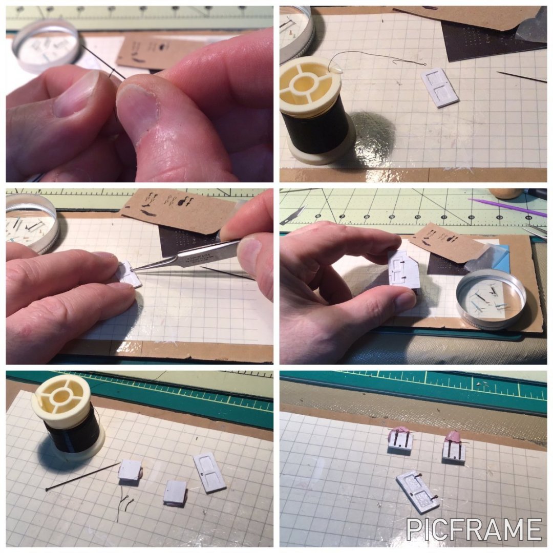
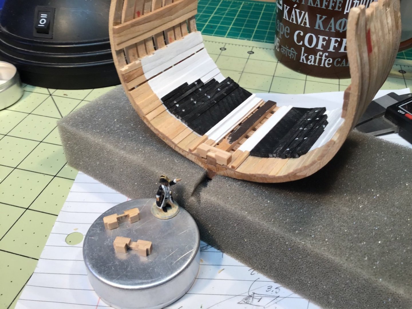
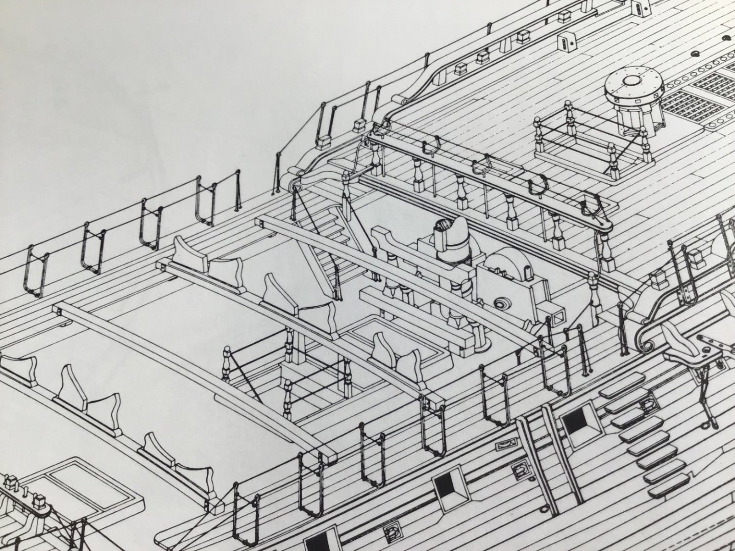
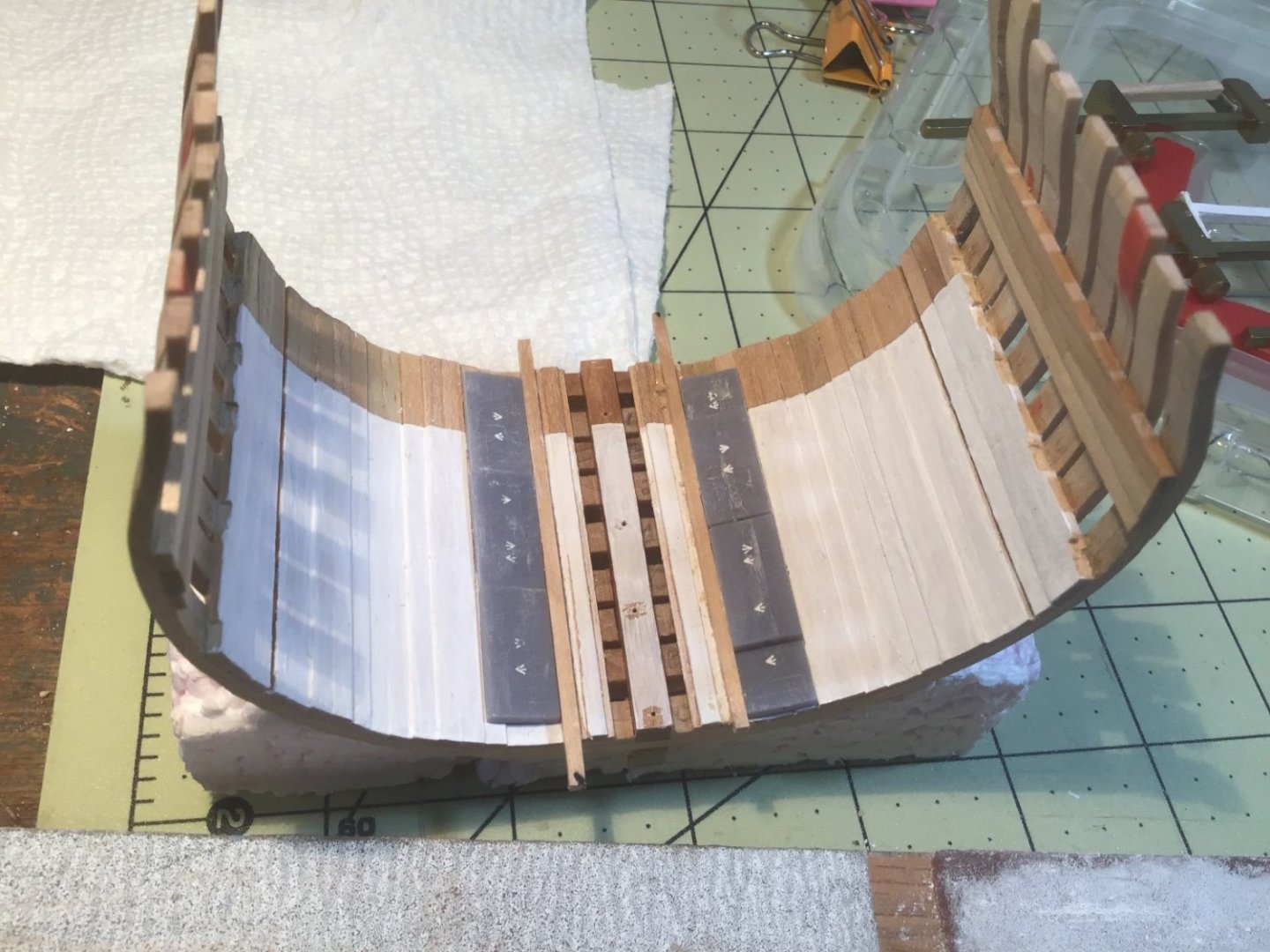
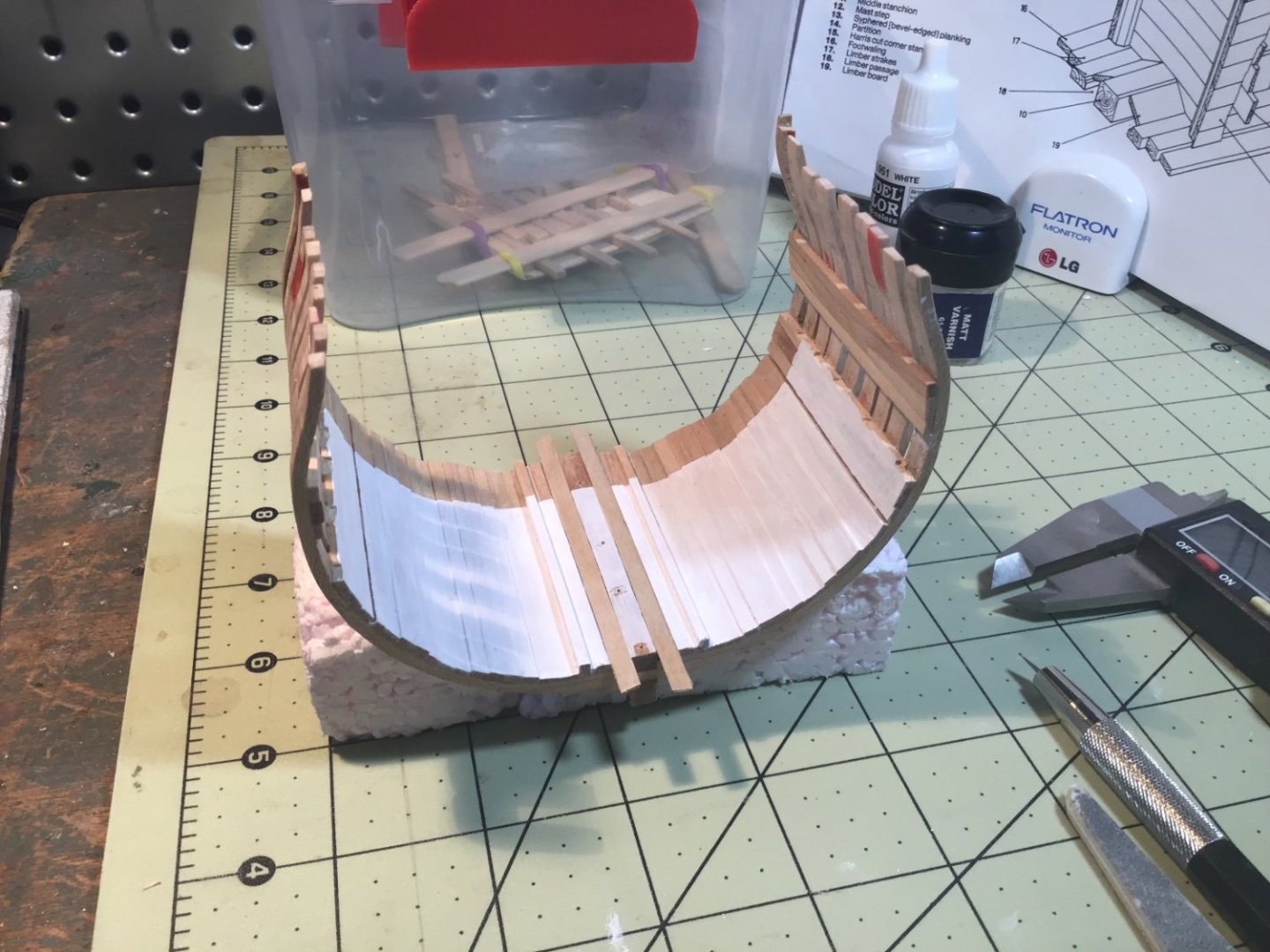
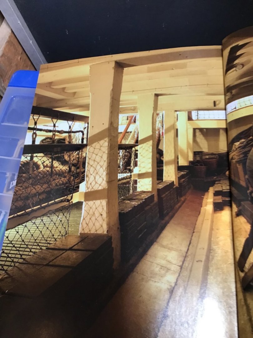
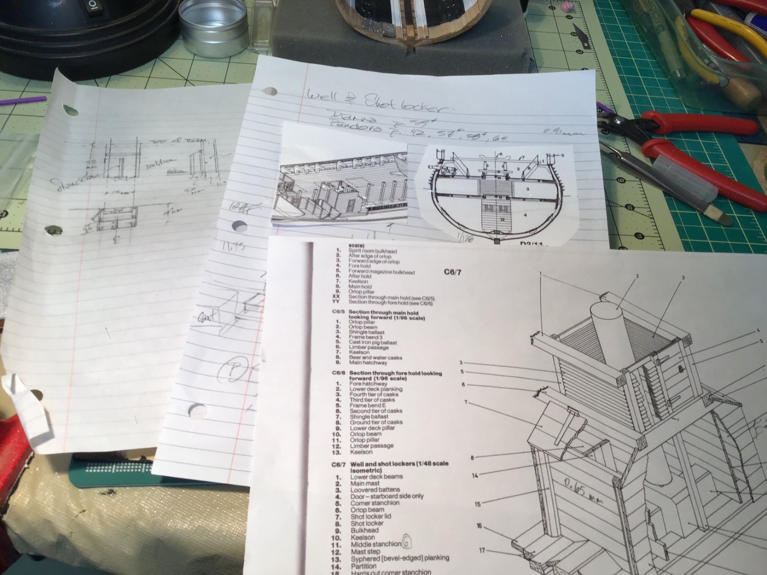
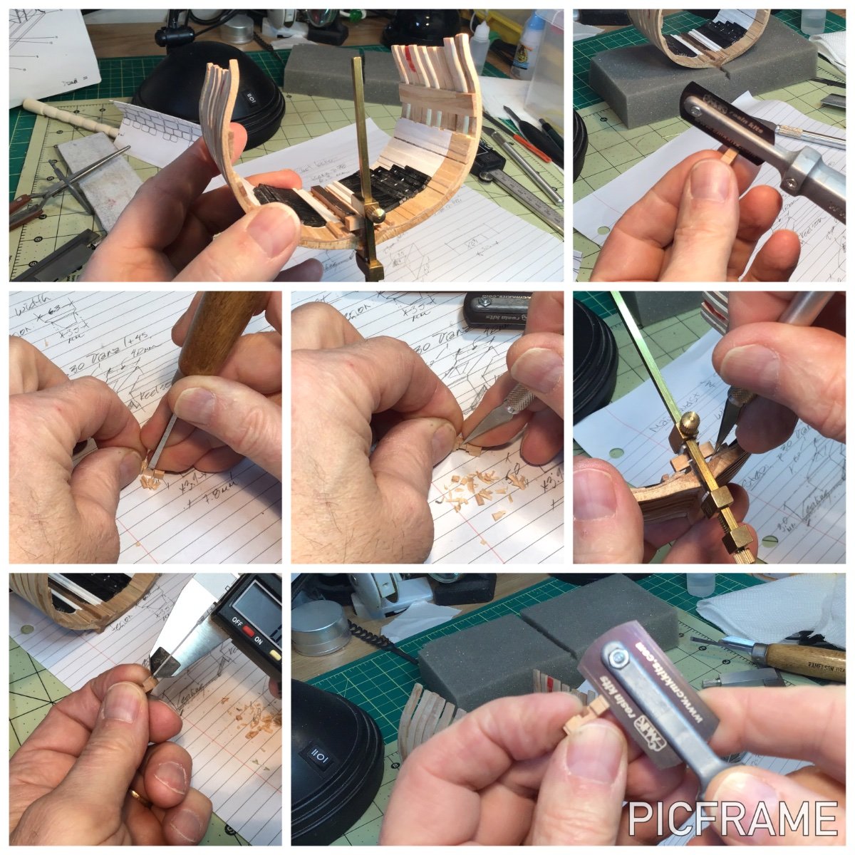
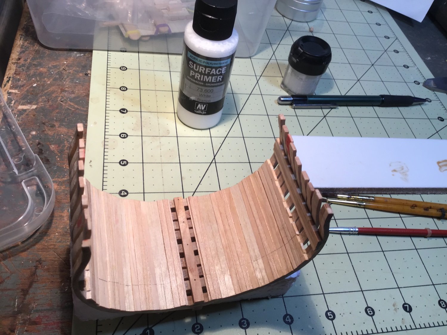
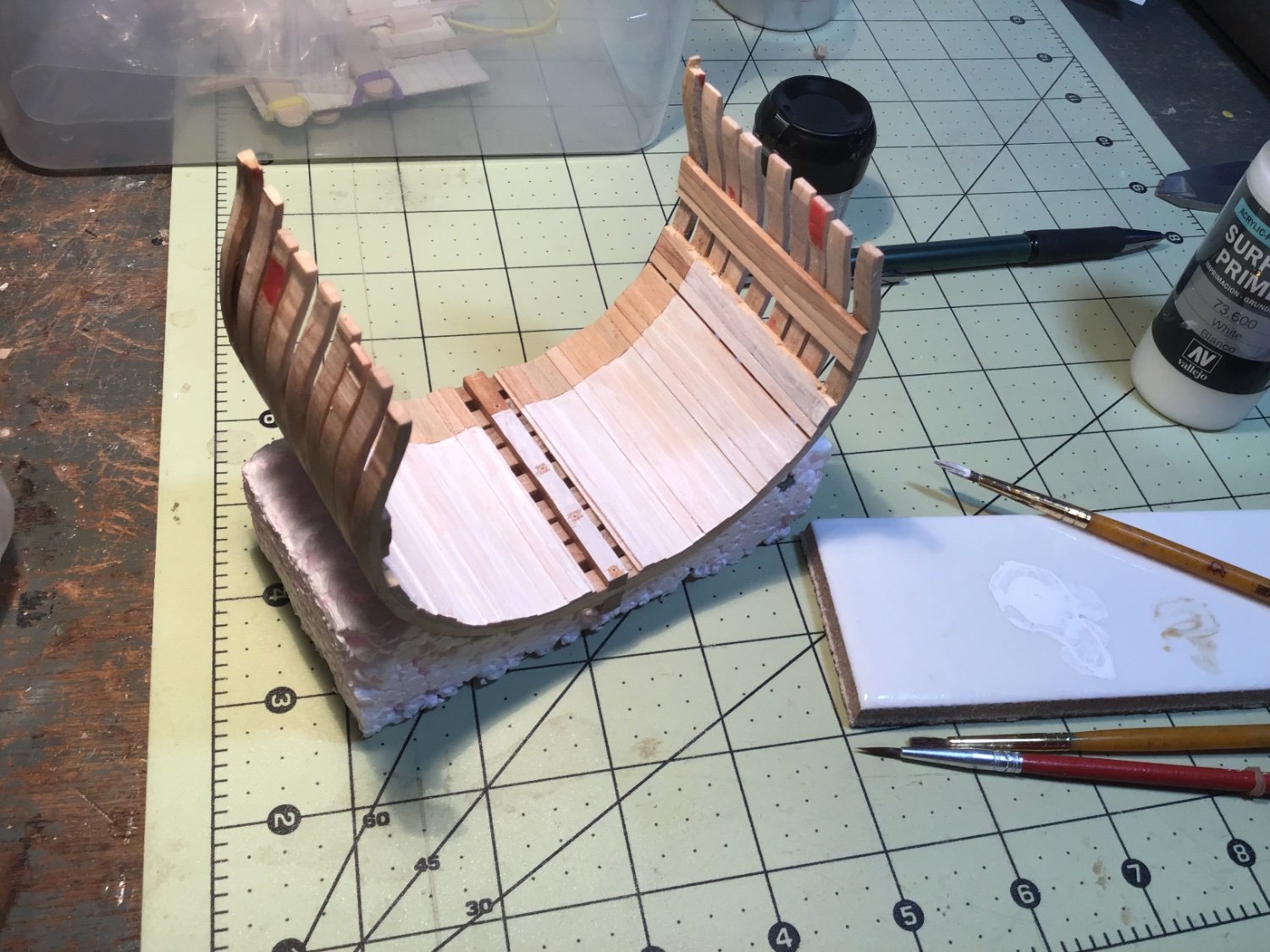
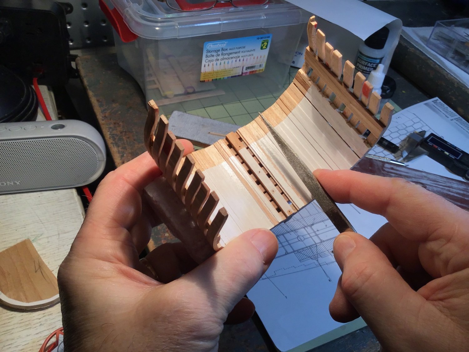
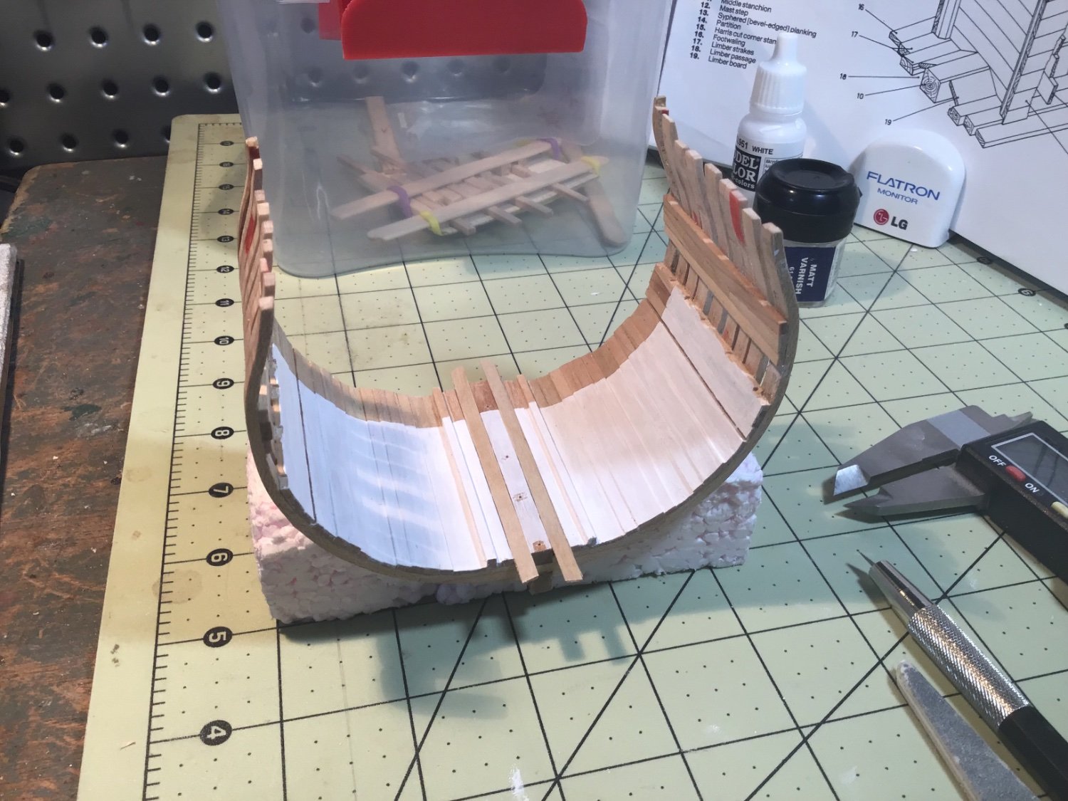
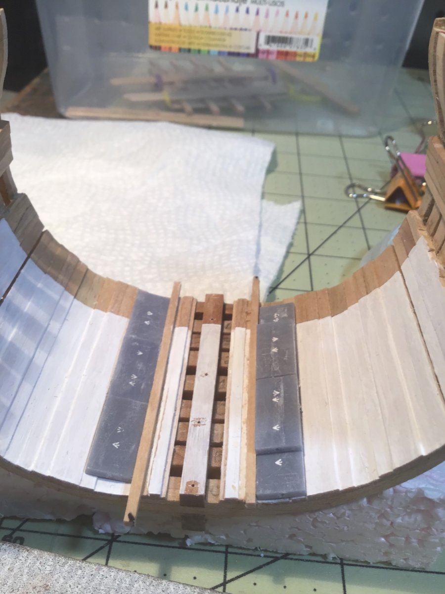
I’m really second-guessing my decision to build the well and shot locker. I’m sure I spent more time building this little thing than I spent on building my garden shed! And, this decision to add the well has created a ripple of changes to the model from the original MSW plans. Thank goodness I have Ainars Apalais’ build log for reference - such a beautiful and motivating model! My final design was an amalgam of four sources: actual photos of period shot lockers from HMS Victory, HMS Trincomalee, plus drawings from AoTS: HMS Diana and AoTS: HMS Pandora.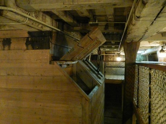

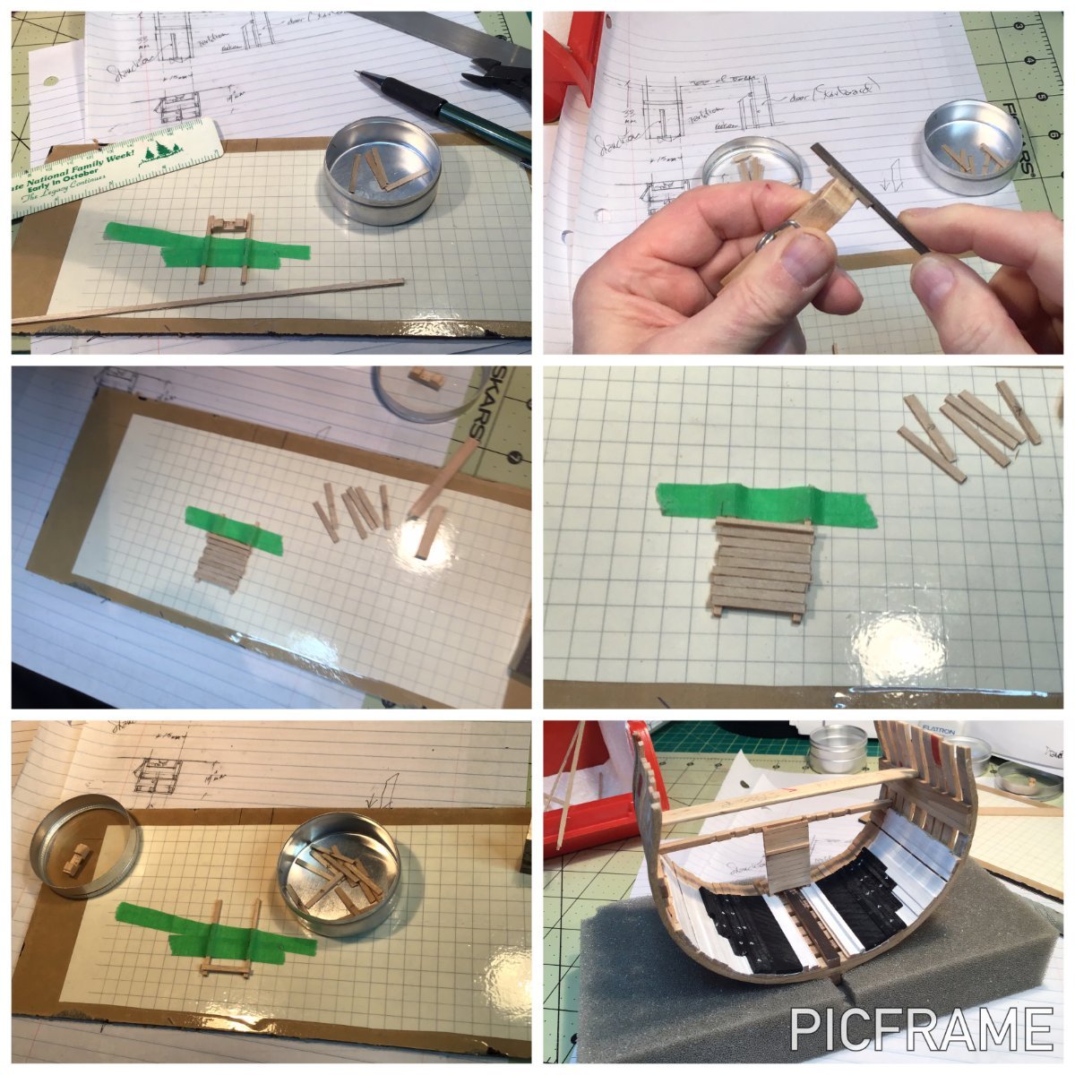
After cutting some 1.80mm square stock from birch for the stanchions I prepared planks using 1/32” - 0.8mm baltic birch plywood. The planks in the well were beveled so they fit together better, so I filed/sanded bevels top and bottom edges. I drew arrows on the planks so I wouldn't get the bevels the wrong way, but it didn't always work! I began with the bulkhead that separated the well and shot locker. As I progressed I came upon several inconsistencies in my model. Of course there were minor flaws in the existing framing and planking of this model - but they became so obvious that it drove me nuts. (Oh yeah, building at 1/96 is another decision I’m regretting!)
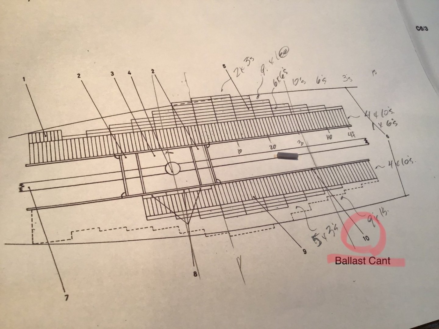
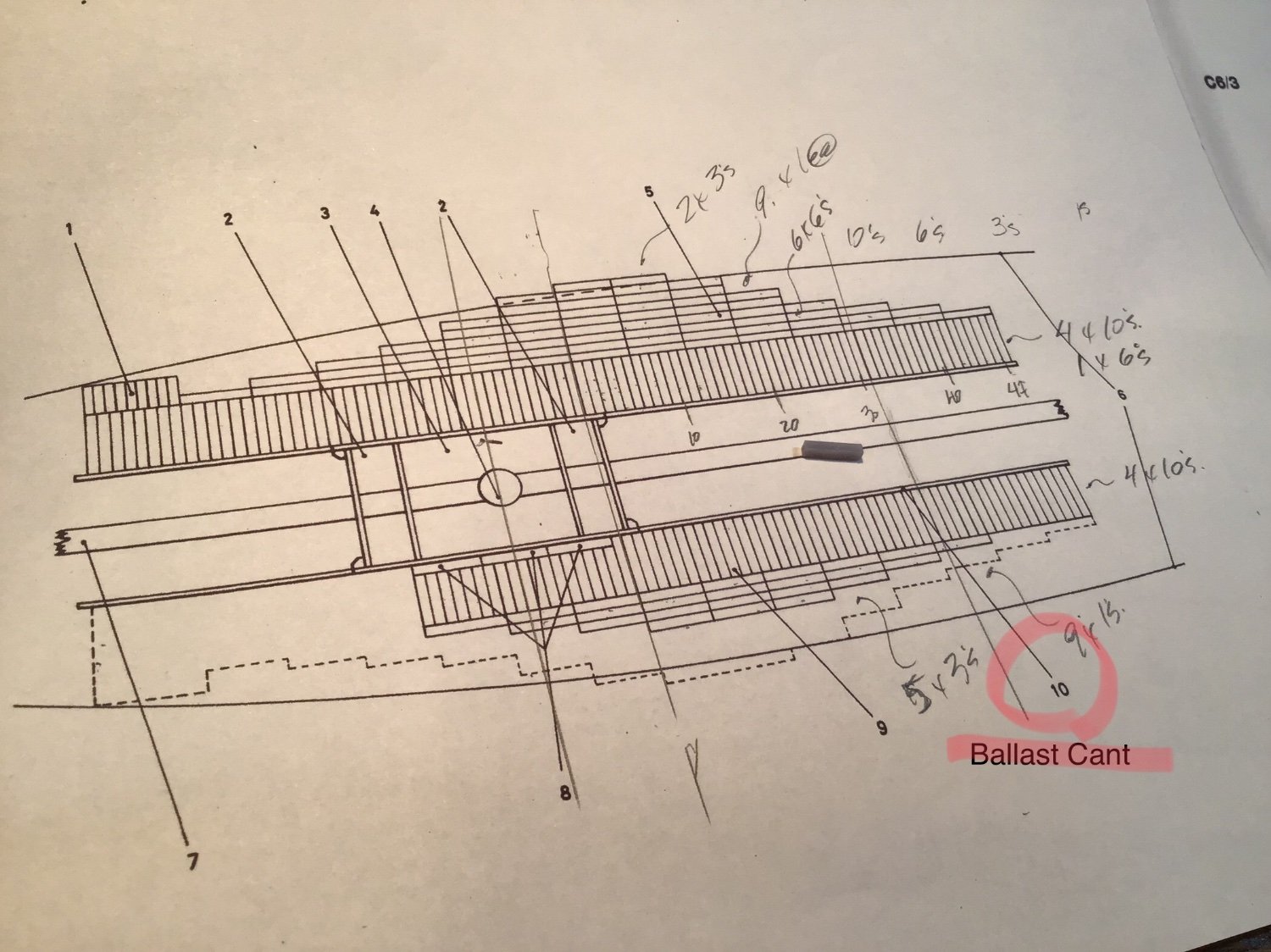
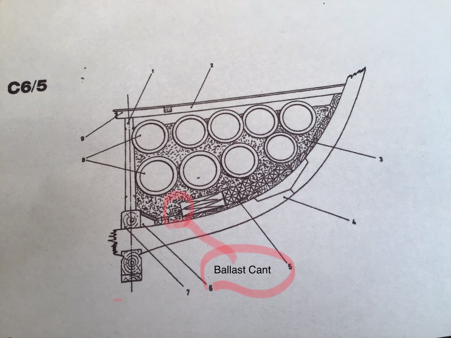
In the incredible AoTS books I also found a couple of errors, the biggest one was that the access door to the well was too low for a ship with all its ballast. The ballast cants are almost never showneven though they are integral to the design of the ship. Because I have included the ballast in this model I was forced to move the door up more than in the drawings. It still looks ok, in my opinion.
Some photos of the process:

.thumb.jpg.132b83a6dce8b8bcb9aa284ba2e2eab1.jpg)
.thumb.jpg.a19268512ade75075d86fe95158d19e0.jpg)
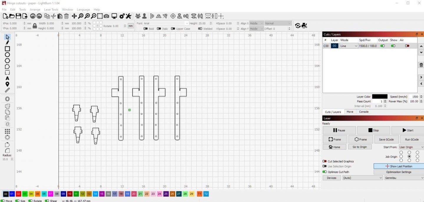
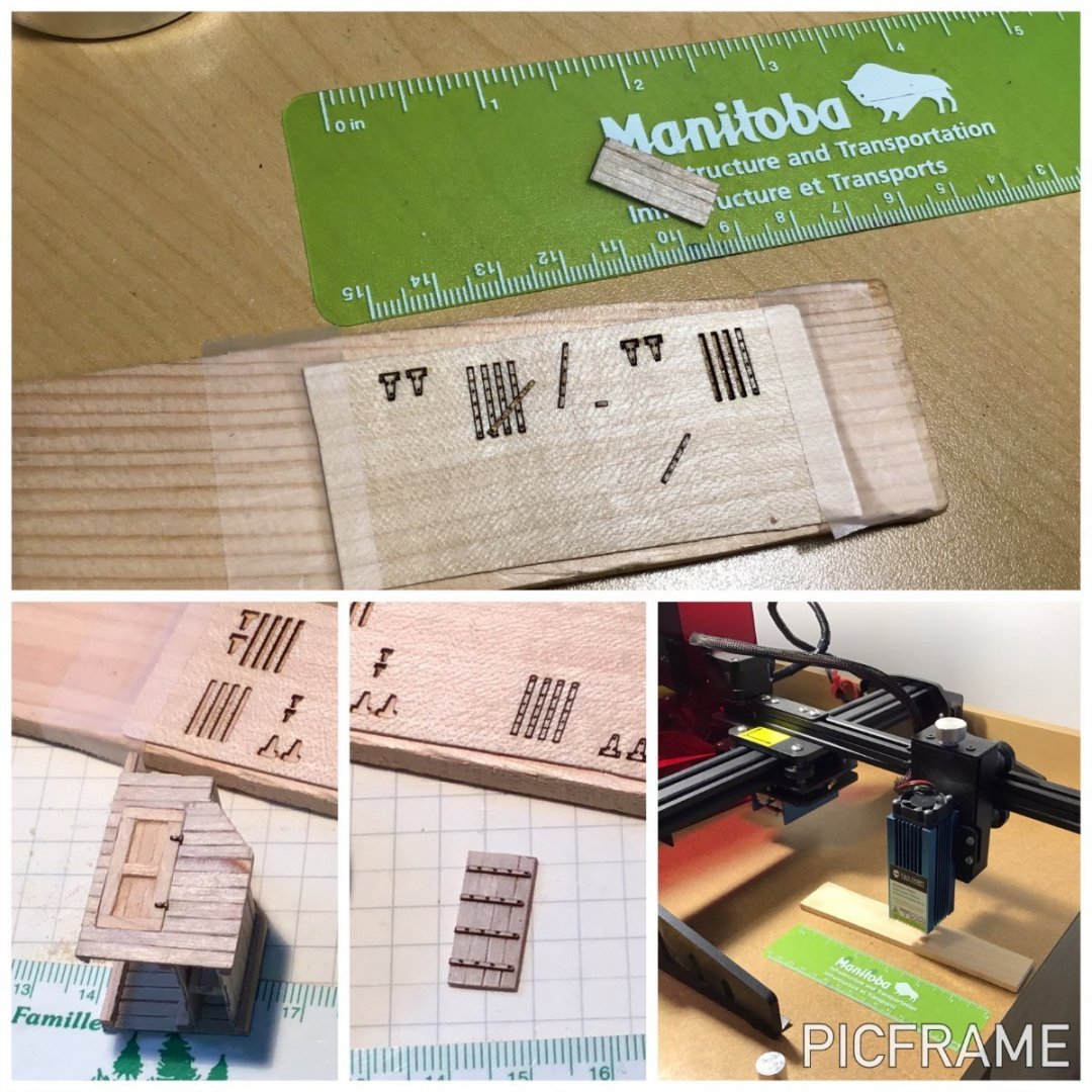
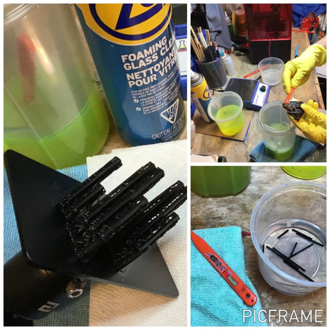
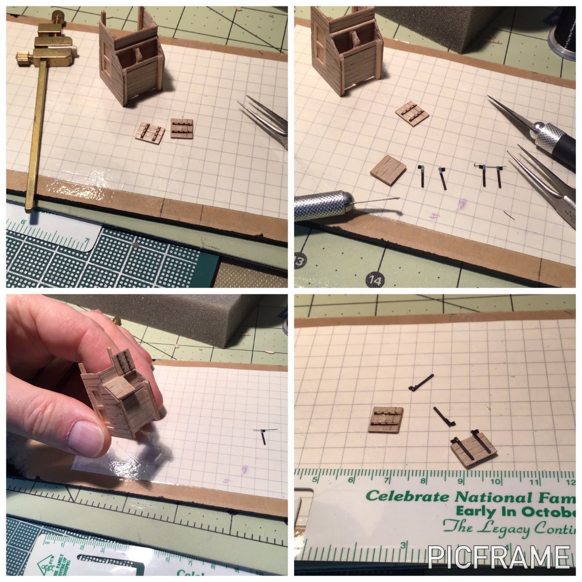
After unsuccessfully trying to hand cut some brass hinges for the shot locker scuttles and the access door I decided it was time to play with some of my toys. First off, I thought I could print these using my resin printer again. However, these hinges were so thin that the prints failed. I'm sure that at 1:48 scale I would have succeeded, but not at 1:96. So I turned to another toy I have: a Jinsoku Genmitsu 1620 laser cutter/engraver. I have been doing mostly engraving hobbies with this small, desktop laser but at 5.5 watts it has enough power to cut through thin wood and some other materials. I have been dying to try this out for some time now. I drew hinges using basic shapes in Lightburn, the control software I subscribe to for the laser. This could have been done in any drawing program and free laser software like LaserGRBL, but Lightburn is much more useful for the engraving I do. My first attempt was to simply engrave the hinges into the shot locker lid. (Top left in the above montage). With a practice piece I got a nice result which would have been fine - it would be inside a tiny model. But, of course, I decided it wouldn't do. I needed something three dimensional.
And again, 1:96 scale came back to haunt me! I started with the thinnest maple veneer I have. The laser cut very well and could even cut the bolt/nail holes in these tiny hinges. But even the veneer looked way too thick once I placed them against the door and scuttles.
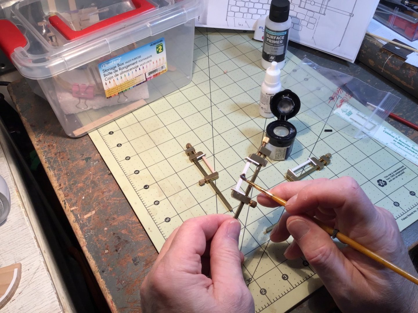
So, I switched to the only wood product that could be thinner: paper. Some blue poster board and a manila folder provided very cheap stock for me to play with. A black felt pen turned them into “iron” and away I went cutting and playing.
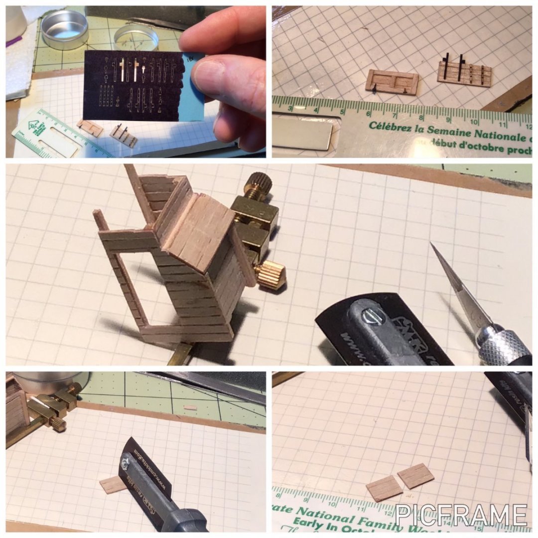
I experimented with folding and gluing the tiny bits of paper to resemble folded strap hinges. Another hobby came into use as I raided my fly-tying gear for fine black wire to represent pins in the hinges! By the way, don’t use CA glue if you try this - the paper became so hard that it snapped and cracked when I tried folding them. Just use PVA. The veneer that I had cut earlier was too thick to represent iron hinges, but it was perfect for the wooden cleats inside the shot lockers to which the hinges are nailed/bolted. So, I glued those onto the underside of the shot locker scuttles.

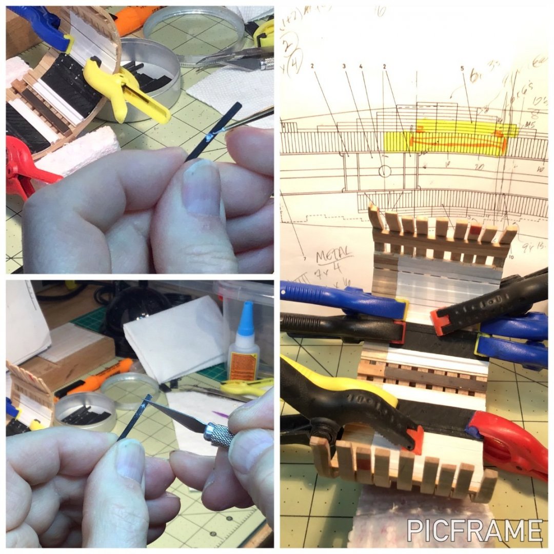
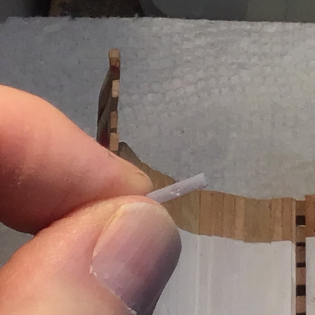
After some painting and varnishing of the well and parts I made some ring bolts using the same, fine fly-tying wire. I found an insect pin that had a diameter close to the diagrams of the ring bolts and wrapped the wire around it. I drilled small holes and pushed the twisted ends of the wires into place. A tiny drop of CA on the inside should hold these in. I placed the paper hinges in place just for these photos.
I won’t install the well and all the associated bits until I do some more work to the hold. Namely, barrels, shingle ballast, lanterns, block and tackle…
...What have I gotten myself into!
Clear skies!
Gabe- Ainars, Knocklouder, scrubbyj427 and 3 others
-
6
-
Bravo, Justin!
Great model - a masterpiece! Such a shame that the photos of your final stretch vapourized on you, but the end result is stunning nonetheless.
What do you have planned next?
Clear skies!
- Gabe
- Justin P., Edwardkenway and mtaylor
-
3
-
Welcome aboard, Ken! You've come to the right place for advice…and the Bluenose is a popular model (of course!🇨🇦) so there will be lots of ideas and help available.
Clear skies and sharp tools!
- Gabe
- Peanut6, Keith Black, mtaylor and 2 others
-
5
-
-
Hello folks!
I really enjoy playing around with my Elegoo Mars resin printer which I purchased primarily to build parts for models. So, I decided to experiment with some printed pieces in my HMS Triton build (link in the signature). One of my reference books for the Triton is Anatomy of the Ship: The Frigate Diana by David White and it includes the layout of the iron ballast (aka kentledge, iron pigs). Simple geometric shapes seemed like a good beginner's project so I used this as my tutorial for Fusion 360 software (free for non-commercial use). Included in this post are two .stl files for full- and half-pigs, complete with the British broad arrow. I have also uploaded them to the pantheon of 3d printing - Thingiverse.com.
https://www.thingiverse.com/thing:5360861
Full Iron Ballast with Broad Arrow .stl
Half Pig Iron Ballast with Broad Arrow v2.stl


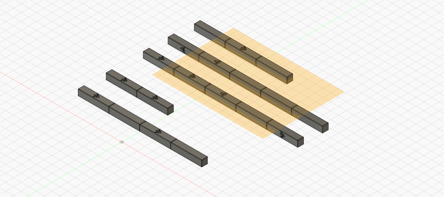
The ballast was drawn to a 100mm length so these files will need to be scaled to your model. A reduction to 20% of this size would be suitable for a 1:48 model. For my 1:96 Triton I scaled the original down to 10%.
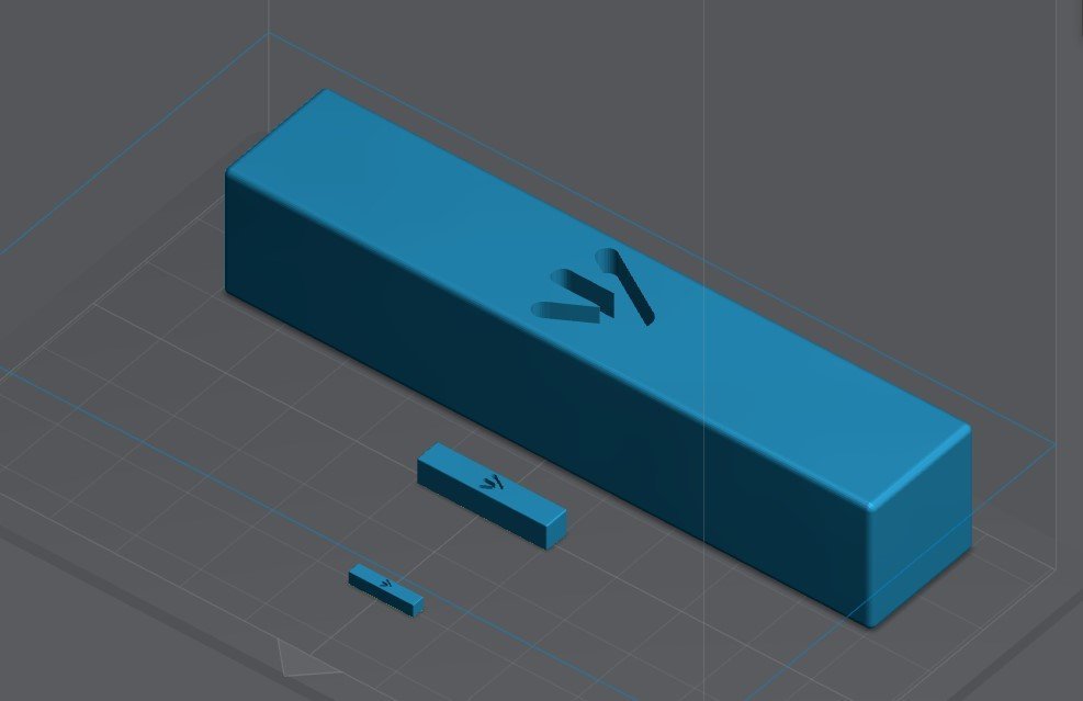 <<< The 3d ballast object at 100%; 20% (1:48); and 10% (1:96)
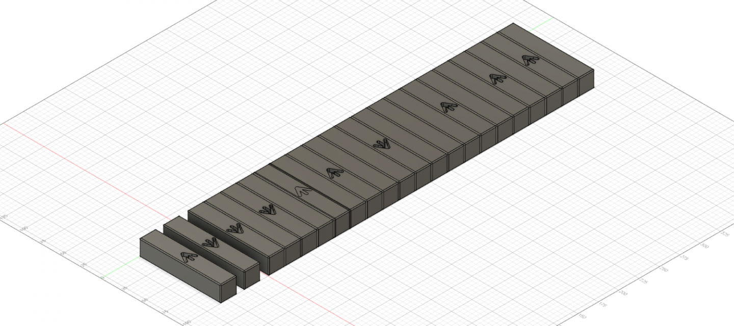
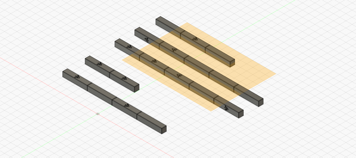
I tried out three different resins - ending with eSun's black, plant-based for the final product. I tried different combinations of printing these in "gangs" to make gluing them into my 1:96 model a little easier. According to several diagrams I have seen, the first row of ballast was placed perpendicular to the keelson while the subsequent rows would have been laid parallel. I chamferred the edges of single ballast files so that lines demarking separate pigs would show up when printing them in gangs. I thought it would have been a cruel officer or, more likely, a vicious bosun who would demand that these 300 lbs blocks of iron be oriented with the broad arrows facing up and in the same direction - so I generated a table of random numbers to help me orient these in a random manner. I am unsure if there would be vast differences between countries but if you wanted to use these for a ship of a different nationality just make sure the arrows are turned away from sight. I did not upload these "gang" files since each model will have different requirements.
If you find these useful and actually try them out at some time, please send me a PM and perhaps share a photo.
Clear skies,
Gabe
-
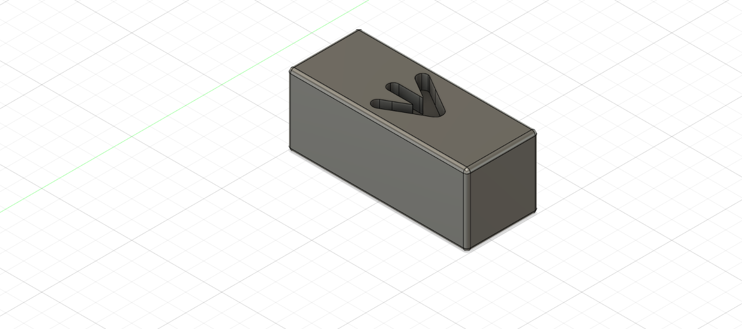
Third time a charm…
Thanks to everyone for their comments, likes and views!
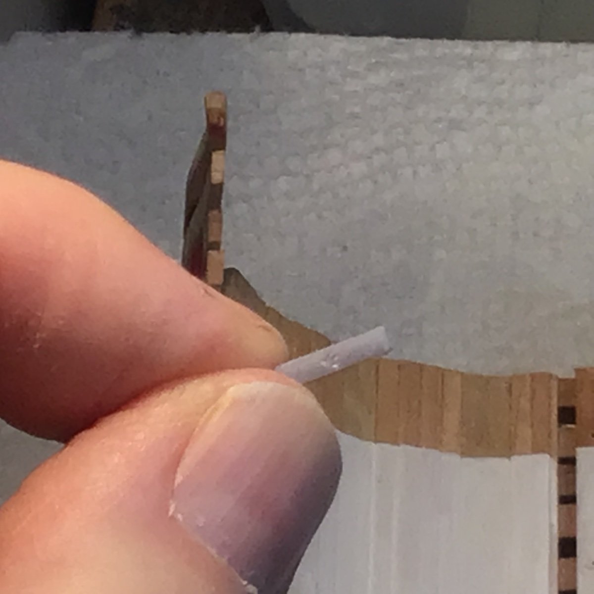
Well, I decided to remake the mast step. First attempt did not fit well, there was a gap that bugged me. The second attempt fit nicely but the mortise looked too shallow…when I realized I had flipped the block and cut the wrong faces! Third time…FINALLY!
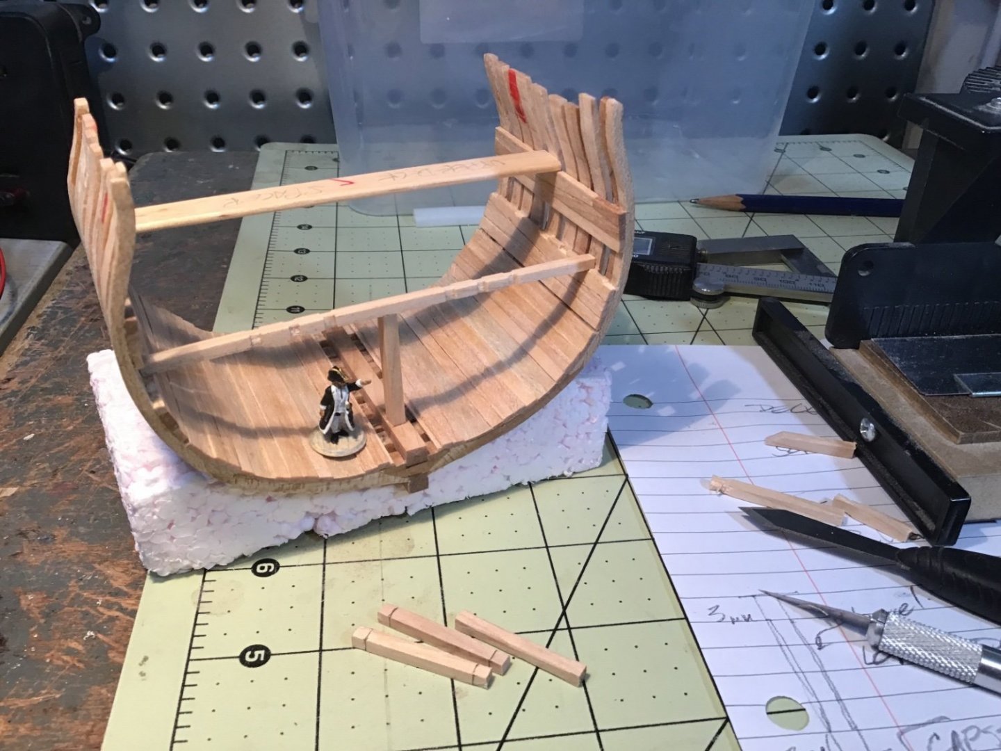
[Number One pointing out the one to use.]
Clear skies!- Gabe
- mtaylor, bruce d and Edwardkenway
-
3
-
14 minutes ago, Nirvana said:
Gabe, another reason for me to get 3d printer up and running, unfortunate it's not a resin printer.
To be honest, Per, I think an FDM printer might produce these simple, geometric shapes much easier than a resin printer. Printing objects flat on the build plate of a resin printer often results in failures. So, the objects need to be tilted and supported. It takes time to create and clean these resin pieces.
You'll be frustrated at times but I'm enjoying this medium!

Clear skies!
Gabe
-
25 minutes ago, mtaylor said:
BTW, you might consider a post in the 3D printing area on the ballasts you did.
Thanks, Mark!
Yeah, Number One is likely going to get his way. But it fits SO nicely...😭. Not sure if I can pull off another. I'm glad that I didn't glue it down right away!
AND, I did plan to write in the 3D forum very shortly and offer the .stl file I created.
Clear skies,
Gabe
-
Backwards step…big step…little step
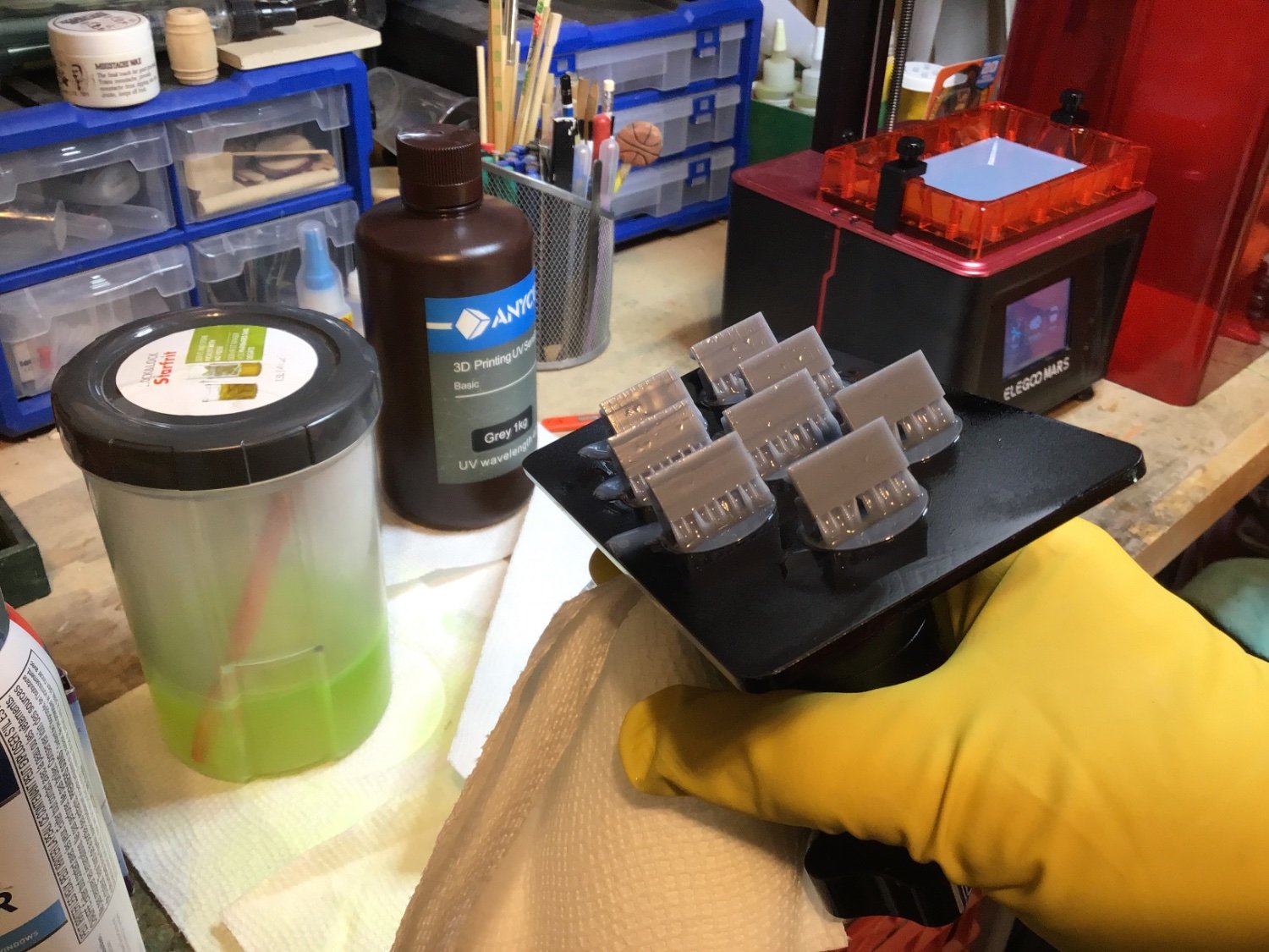
I was a bit disappointed when I painted all the ballast I had printed. In pictures of the HMS Victory the broad arrows on the iron pigs appear to be filled with dust from the shingle ballast. On the HMS Trincomalee the arrows are painted. Regardless, the arrows are noticeable so, after priming and painting all the pieces black, I experimented using some white weathering powder to fill the broad arrows. I was totally frustrated with poor results. I couldn’t keep the white off of the areas that needed to be black: washing, sanding, scraping all led to mottled greySo…I bought black resin and printed all the ballast again. For those of you unfamiliar with resin 3D printing, there are many manufacturers of UV resin and many different formulations. Because of this variability there is always a bit of a learning phase to get good results with new resins. (This particular resin was eSUN’s plant-based product. If you want the settings I used please let me know). After several mediocre results I was able to start up the resin foundry into full production again.
I did find that some pieces were slightly bent after I cured them and I wasn’t sure which stage of the process was causing this. They appeared fine before I cut them off the supports, so I printed several more than I needed and experimented with post-printing procedures. (Again, if you’re interested just ask and I’ll fill you in on what I ended up doing.) Another perplexing issue was that there was an artifact from printing - diagonal lines on the larger ballast pieces that were printed facing in one direction - but the pieces printed in an opposite direction were smooth. In the resin world there is speculation that this is caused by the software used to prepare a 3d file for printing.
When time came to add the ballast to the model I realized that the first row, which runs perpendicular to the keel, was too long for my future plans so I had to cut it back. While this doesn’t seem to be a big deal to many, standard UV resins are remarkably brittle so I anticipated trouble. Either plant-based resins are more resilient than the standard formulae or I was careful enough to manage shortening them without mishap.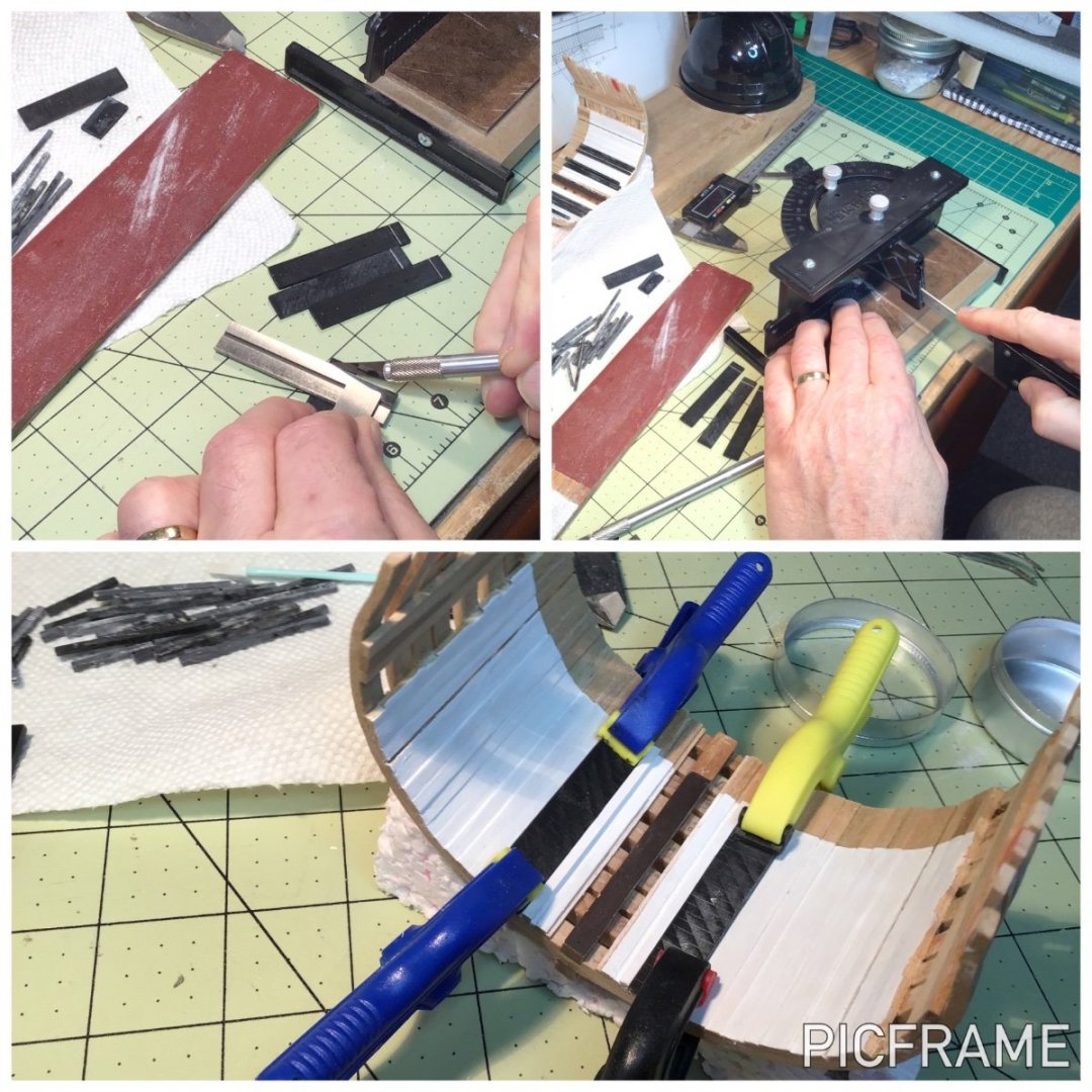
Something else became bothersome - sanding this resin produces a very fine, white (light grey?) powder that clung to everything. It almost became like paint and I had to scrub the ballast clean using water.
If I thought painting the hold was nerve-wracking enough, gluing these ballast pieces into place required a BIG gulp. I could always sand off paint, but once these are installed there’s no going back. It all worked fine. I didn’t bother painting the broad arrows on these starter rows because they will be hidden by a second tier - but parts of the rest of the ballast on this first tier will be visible in places. Therefore, I painted them using thinned, water-based Vallejo white and, once dry, scraped the paint off the surface of the ballast.
Now that I know the extent of the ballast I won’t install the second tier until later after some more work in the hold is done. Namely…
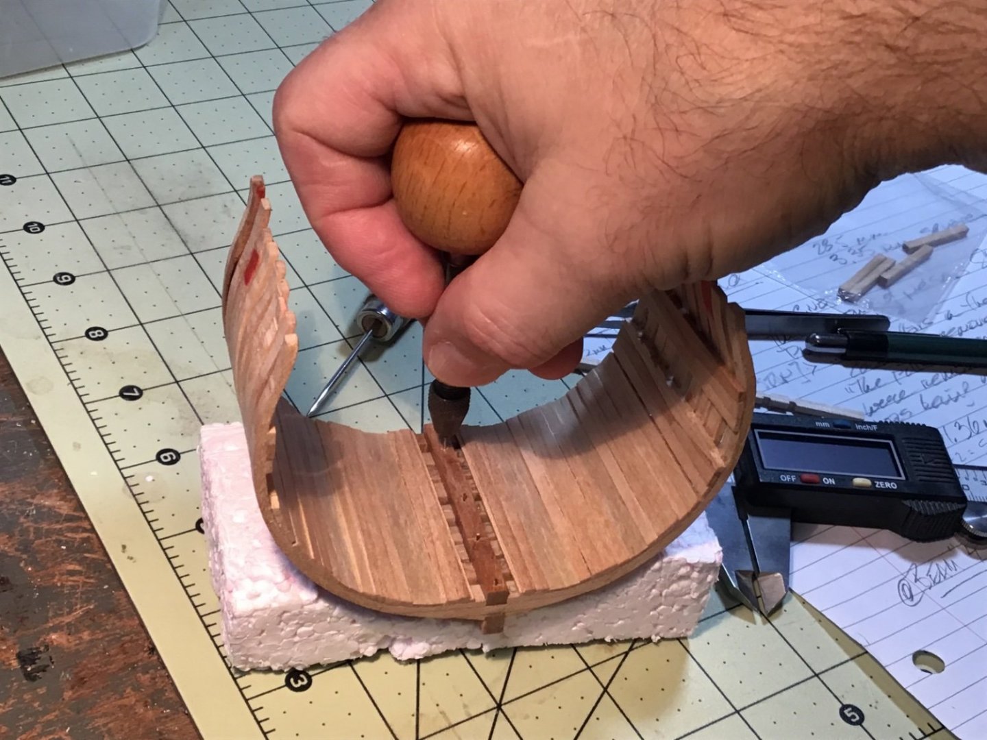
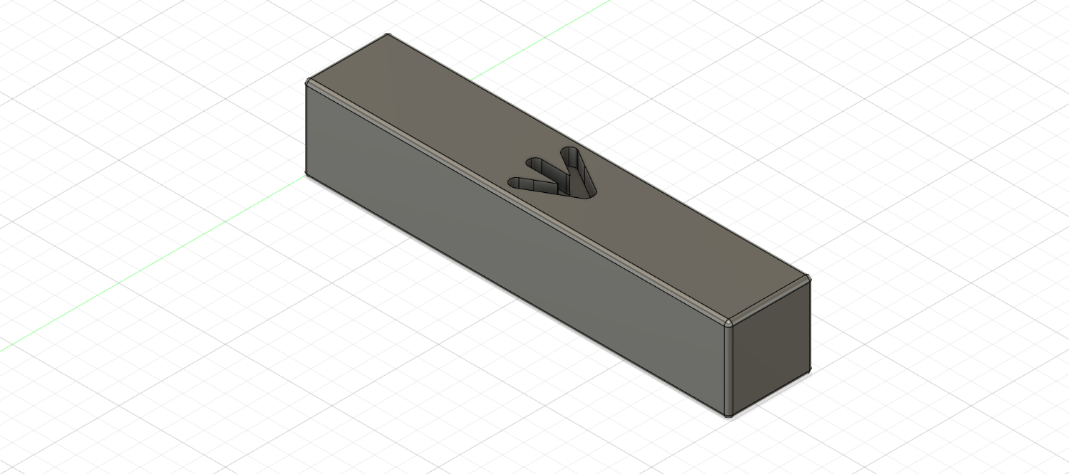
…the well and shot locker are next. It all starts with a cutaway main mast step. Poring over diagrams in Anatomy of the Ship: The Frigate Diana and AotS: The 23-Gun Frigate Pandora plus photos of the HMS Victory in Longridge’s The Anatomy of Nelson’s Ships - they seemed to indicate that the mortise for the main mast was cut through the mast step and the heel of the mast would sit on the keelson. Starting with a block of birch 4.0 mm x 3.0 mm x 15.0 mm, I carefully marked lines with a knife and, with a very sharp chisel and xacto knife, managed to fit it quite nicely around the keelson and limber strakes - complete with a mortise through to the keelson. In this process I discovered that there was a small warp in the keelson! A bit of filing messed up the paint, but I can easily touch that up.
I was very happy with the fit. That is, until…
I happened to spot a drawing in AotS: …Diana (p. 30) where I finally could see that the mortise was NOT cut through! Ok…I’m going to stop and collect my composure before deciding if I should repair or replace the nicely fitting step I made.I think Number One wants this step off the ship…
-
Excellent work, Pat.
Just so happens that Daz is sitting on my desktop ready for me to soak hours into! Glad to see the fabulous results you’re getting.
Clear skies!
Gabe
-
On 2/12/2022 at 12:47 PM, Roger Pellett said:
Here are my bagpipers…
Wow! The tartans must have been a real challenge! Well done, Roger!
- Gabe
-
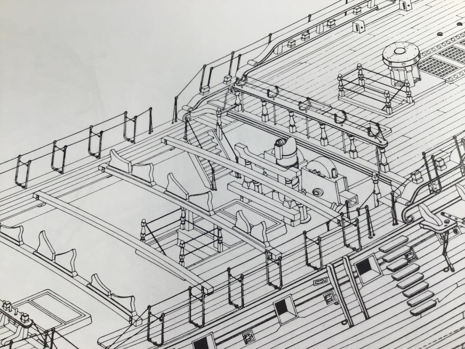
Great work on your Triton! Well done.
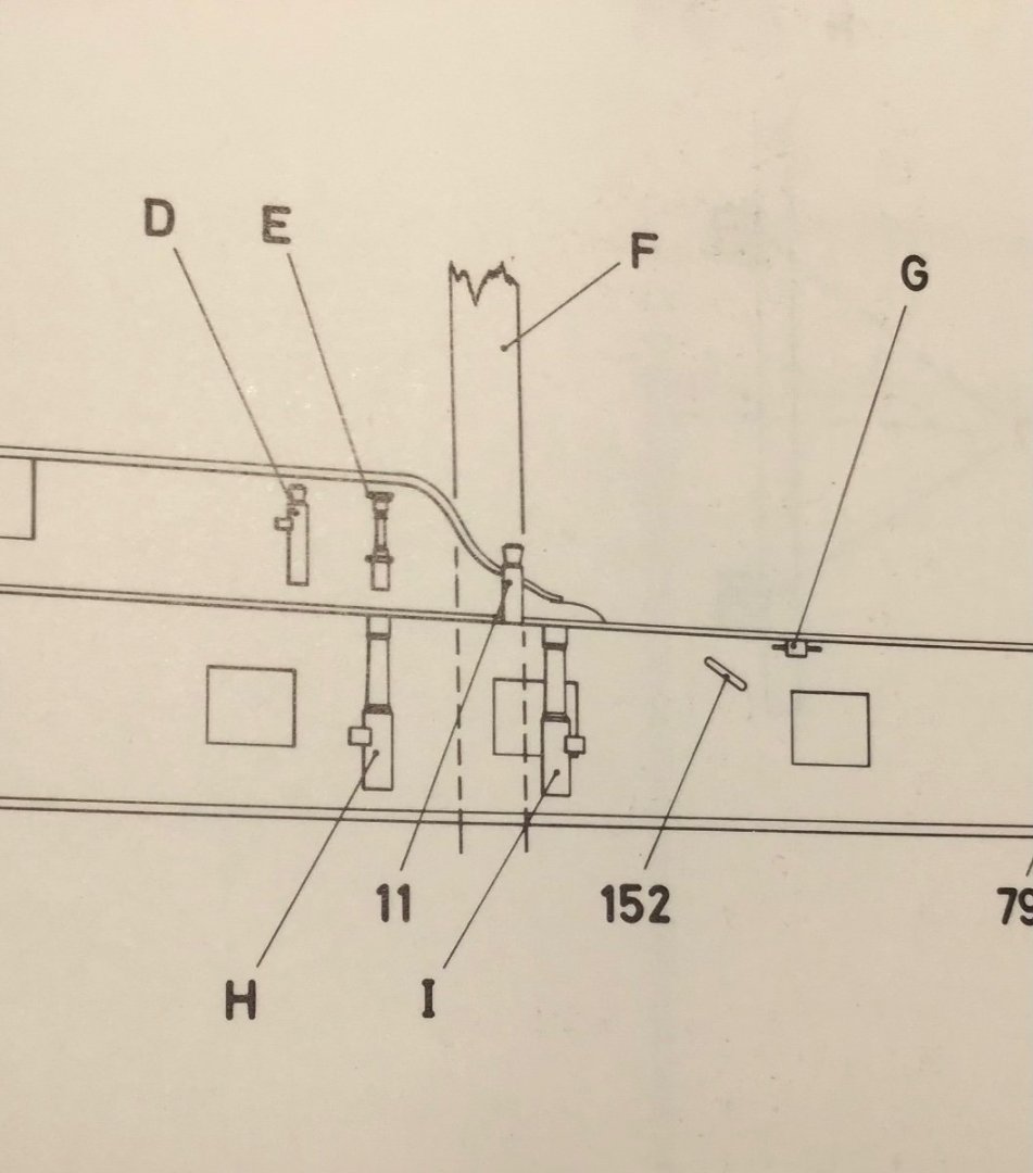
Here are a few pictures from Anatomy of a Ship: The Frigate Diana (White, 1987) and AotS: The 24-Gun Frigate Pandora (McKay and Coleman, 1992) that might help.
Clear skies and sharp tools!
- Gabe

- shipcarpenter and mtaylor
-
2
-
Thanks for all the supporting comments and likes, folks!
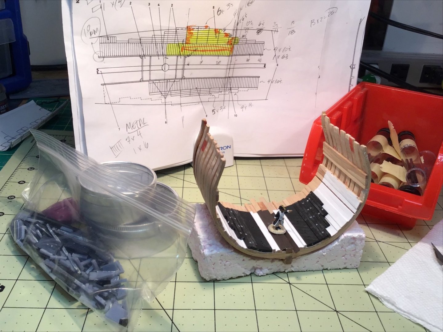
This was a psychologically tough stage - painting the hold. Even drawing a pencil line on that clean wood gave me heartburn! For quite some time I guessed and second-guessed this decision but when I sat down to do this there was no hesitation. I started with a Vallejo acrylic primer, followed later by Vallejo white. The aft part of the model will remain unpainted. The three forward-most pillars were painted as well. Once everything was dry I brushed on a matt varnish to the entire hold and all pillars.


So, while things were drying I was drafting the iron pigs in Fusion 360 (free version) based on the proportions and layout according to Anatomy of the Ship: The Frigate Diana. In photos of ballast in HMS Victory and HMS Trincomalee you can see the ubiquitous British government broad arrow so I added them to the design. By my count, I would need over 200 pieces of this permanent ballast. Rather than printing 200 single pigs I created side-by-side “gangs" of 10, 6, and 3 along with some singles. I soon realized that end-to-end gangs could be used so I designed sets of 2, 3, 4, and 6. [I plan to dedicate a post to this whole process shortly].

Looking closely at the Diana plans I discovered I had to add ballast cants that run parallel to the limber strakes and act as a stop for the iron ballast. The cant can be seen in the photo of HMS Trincomalee's hold. Yes, I had to add pieces to the FRESHLY PAINTED AND VARNISHED hold! Well, time to scrape…

I made suitable stock on my table saw, scraped the paint + varnish so I could glue down the ballast cants in place. I had some ballast fresh off of the printer and couldn’t wait to see how things looked together.

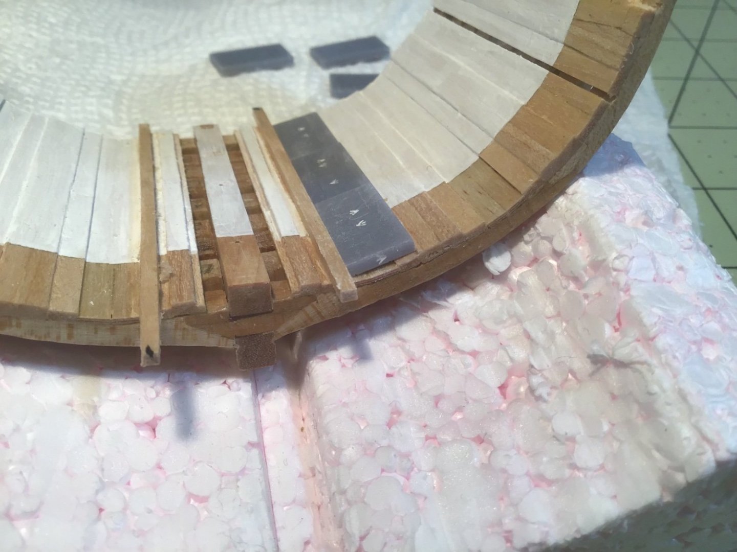
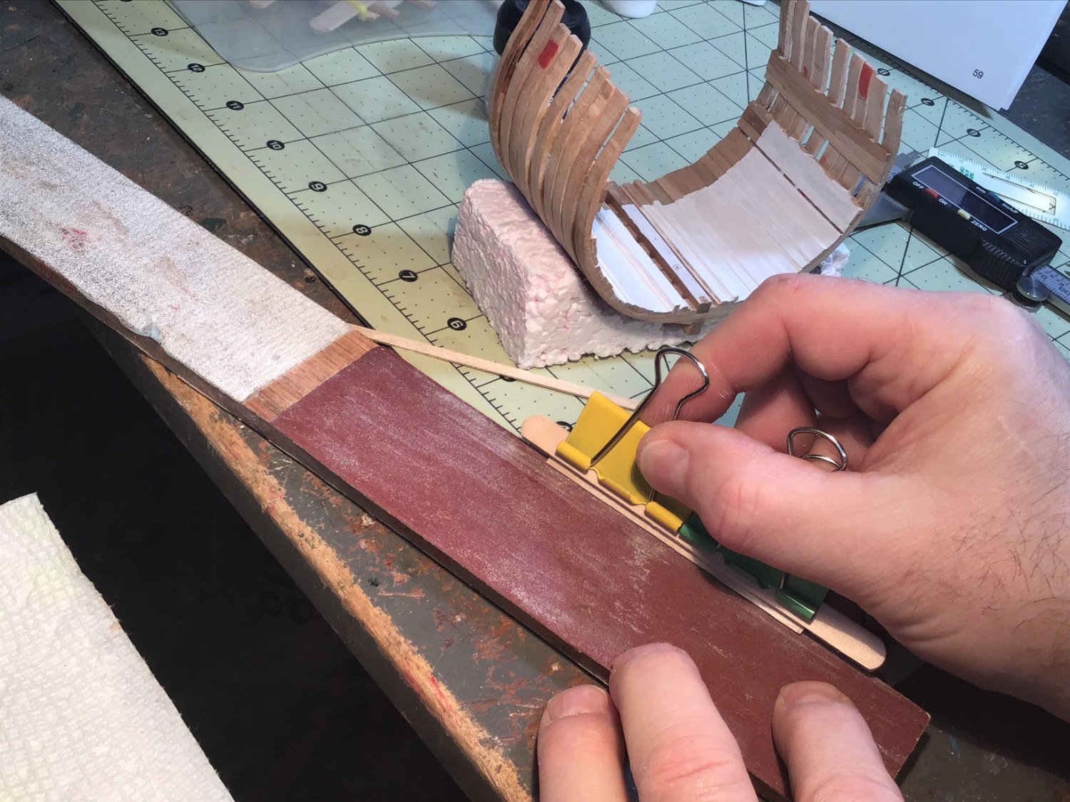
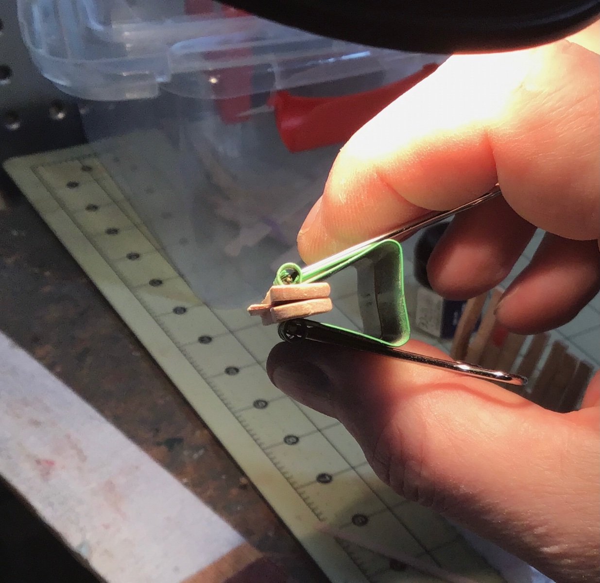
After trimming and painting the newly installed cants I went to work on the limber boards. To get the bevels on the edges of such thin, flexible strips I ended up clamping the pieces between two popsicles sticks. This let me hold them at a constant angle, making the bevels on the limber boards quite sharp.
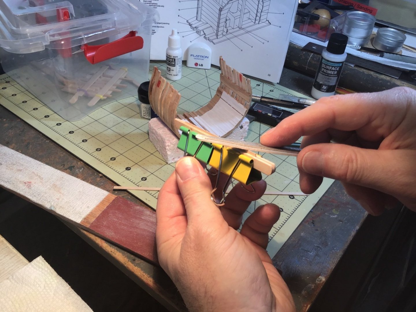


Once shaped, I painted the limber boards (and the keelson) a dark brown based on HMS Trincomalee. I was going to cut the limber boards shorter but couldn’t find the correct lengths. I was going to ask you folks if you knew the right dimension until I discovered it a few minutes ago! Looking at the photo of the Trincomalee's hold just now I can clearly see the cut lines. Before I install them on the model I will chop these to an accurate size.
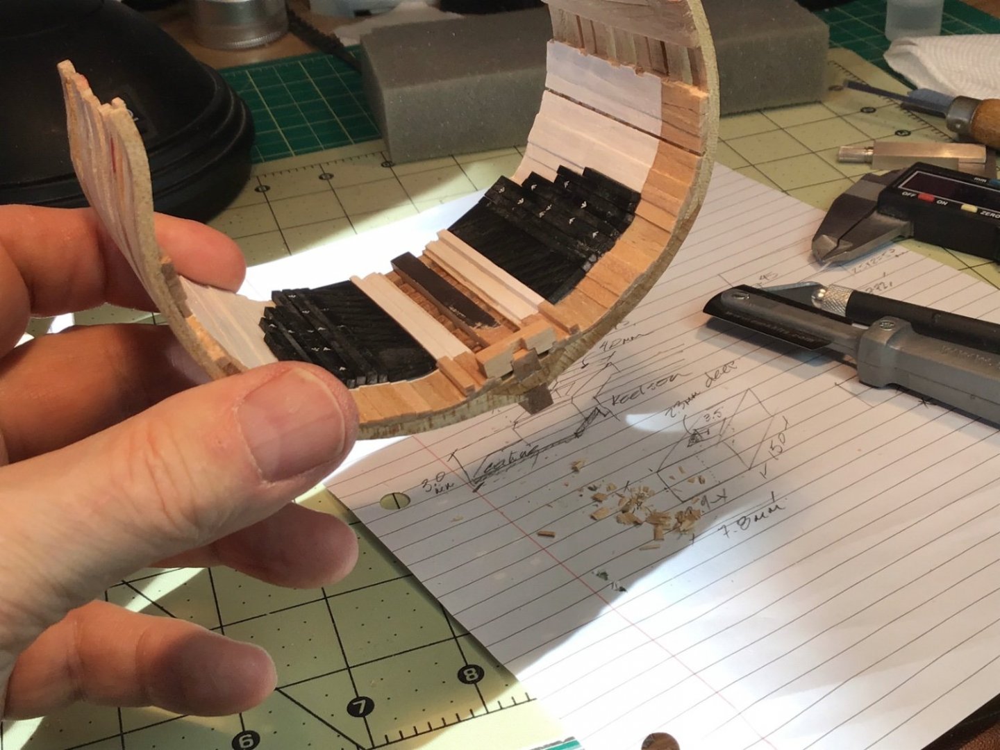
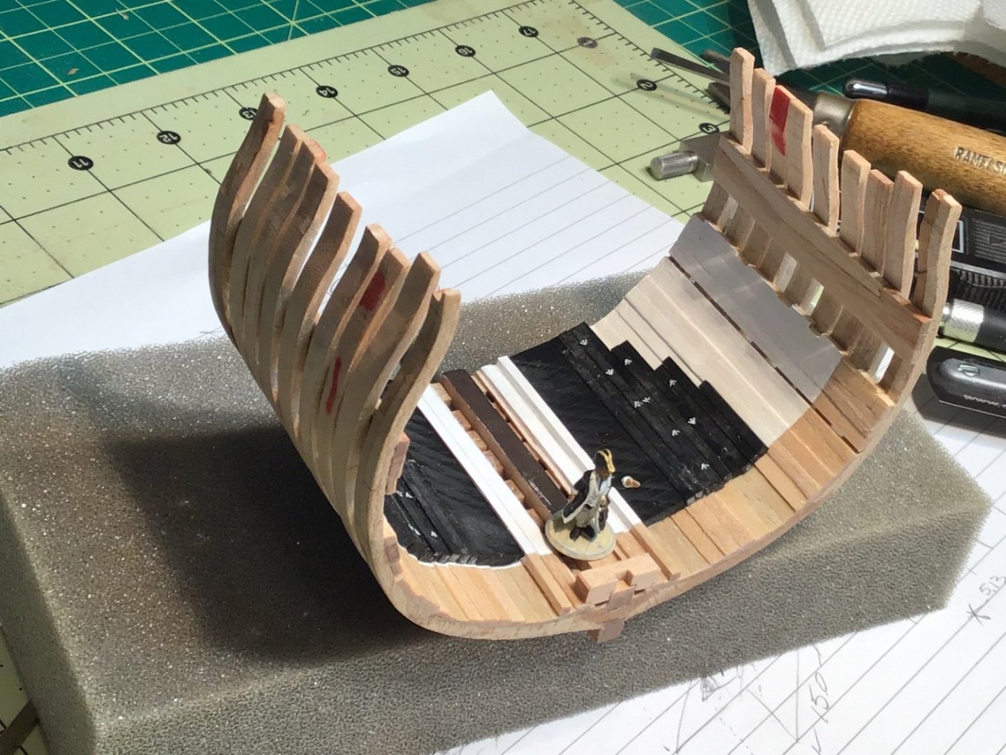
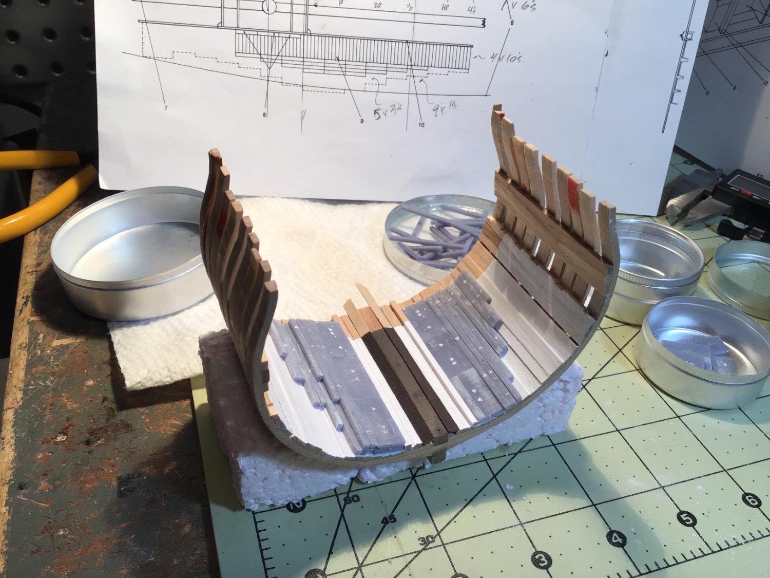
Again, I was so excited that I couldn’t wait to paint all the ballast I had printed before dry fitting to my Triton. So, with limber boards in place, this is what the iron ballast on a frigate would look like:

Iron ballast was arranged in three tiers (see the previous layout photo). The starboard side of the hold (left in the picture) has an accurate set up with two tiers (the third tier would be just a couple of pigs next to the well). The port side (right in the picture) is only the first tier. The broad arrows look white but are just filled with resin dust from sanding. I took pains to print the arrows in a random pattern (using dice!).
I'm amazed at the amount and breadth of the ballast on these ships! I'm glad that I’m adding them. Painting and installing them permanently is next (gulp!)
Clear skies,
Gabe
- bruce d, shipcarpenter, mtaylor and 2 others
-
5
-
3 hours ago, wefalck said:
However, I find that these Heroforge figurines look to much like 'wargaming' figurines (which they probably are) - their proportions are too stocky built, too long extremities and too big head for the body.
Also the trousers look a bit strange, the crotch sits too high to be comfortable not to say that they would impede the movement up in the rig. At that time trousers were cut very high on the waste, so that the body is well-covered by the relatively short 'monkey'-jacket.
Thanks, Roger.I agree. While there are many options for dress and body in HeroForge you really can’t do anything lifelike or historically accurate. I plan on working a bit more in the application MakeHuman (http://www.makehumancommunity.org/). FULL control of proportions and you can create any style clothing. It is very community-based and people share their designs readily. If I manage to find or create something that looks good I'll share it here.
Clear skies!
-Gabe
-
1 hour ago, Keith Black said:
…Are you able to print 1:96 figures easily?
I thought I might populate the Tennessee with a few of the crew but I can't find any 1:96 US Navy figures from the 1850 to 1900 time period. If someone has a lead, please advise.
Thanks for the reply, Keith! Things are ok - just going with the flow to cope with this wild time. How’s things on your end?
Honestly,1/96 printing was quite easy. Once you have a .stl file you can make it any size you want. Resin printing becomes an art as you try to avoid failures. You begin to see how to best position the model, tilt it off vertical and add supports.
Although they aren’t perfect, why don’t you go to Heroforge.com and create a few figures. This design step is free and you only pay when you order a print or ask for an .stl file.
Clear skies, sharp tools,
Gabe
- lmagna, Ryland Craze and Keith Black
-
2
-
 1
1
-
2 hours ago, Roger Pellett said:
A question? Why are War game figures misproportioned? The only reason that I can think of is that by making them intentionally too short they are more stable. The better proportioned 54mm figures are easily knocked over.
Roger
I think you’re right about stability. It could also be that "chunkier" models are more durable and details can standout more.
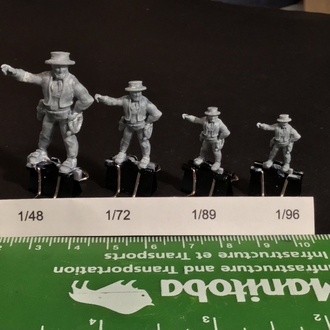
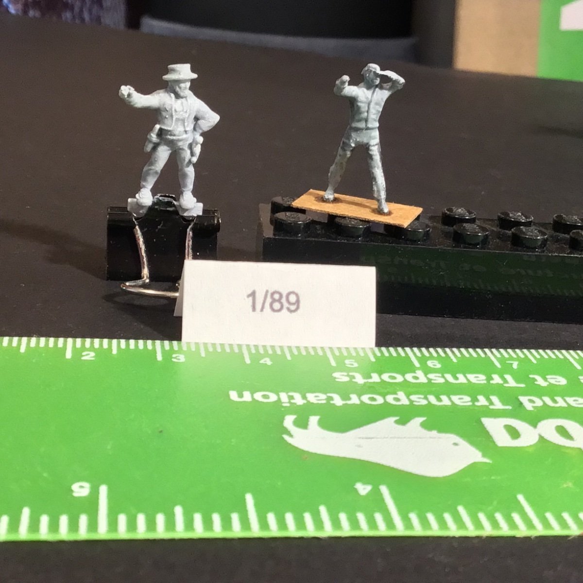
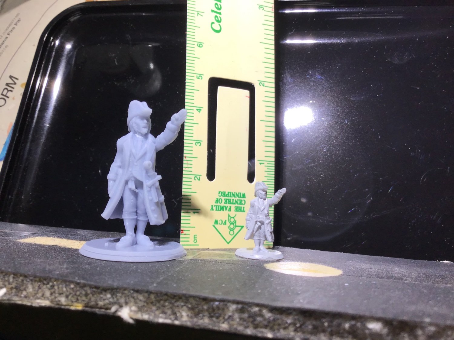
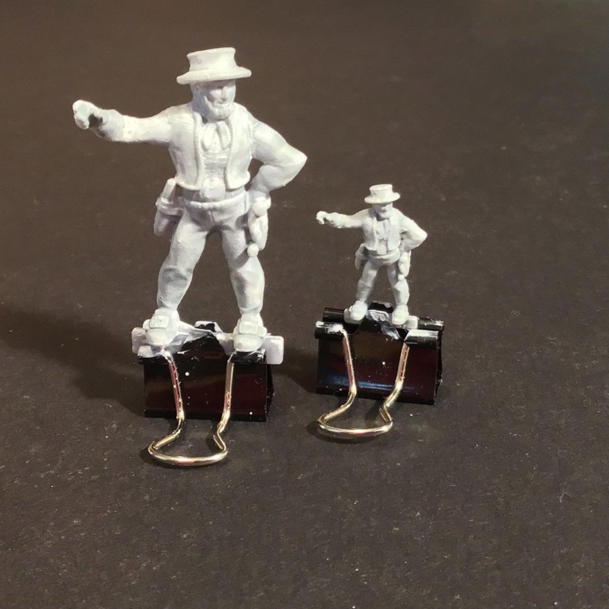
Here are some side-by-side comparisons:
My Heroforge bosun and a metal Artesania Latina l'Hermione figure at 1/89:

Clear skies!
Gabe
And here is a HaT British sailor at 1/72:
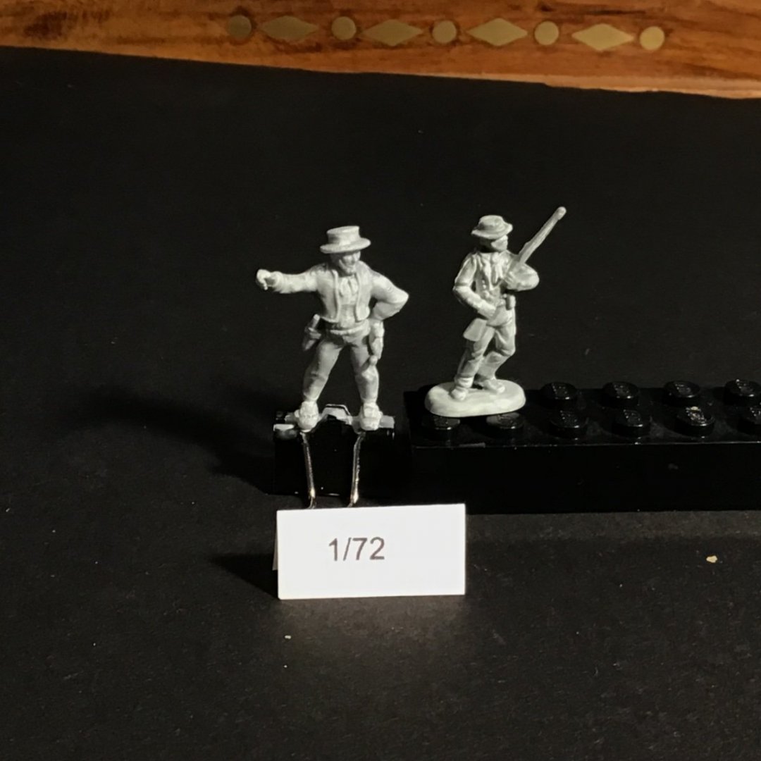
- lmagna, Ryland Craze and Keith Black
-
3
-
12 minutes ago, Dave_E said:
How do you paint something so small?
Good question! I've had a lot of practice…I've been painting miniatures for close to 50 years. This is where my Warhammer hobby comes in handy.
A good, pointed brush and good acrylic paints that are slightly thinned allow you to paint with light touches. Using the side of the brush lets you paint raised features without touching the background. After painting base colours you can use washes, inks or contrast paints which settle in low areas to give you shading effects and a better three-dimensional look. There are tons of "how to" videos on YouTube. If you want, I can list a few.Clear skies!
Gabe
-
I haven’t been working on my models much but I sure am playing with my resin printer! I went to Heroforge to create some more poses for figures and have been playing with scaling.
My rendition of a bosun with a rope's end. The knife is too chunky…I may file it down.
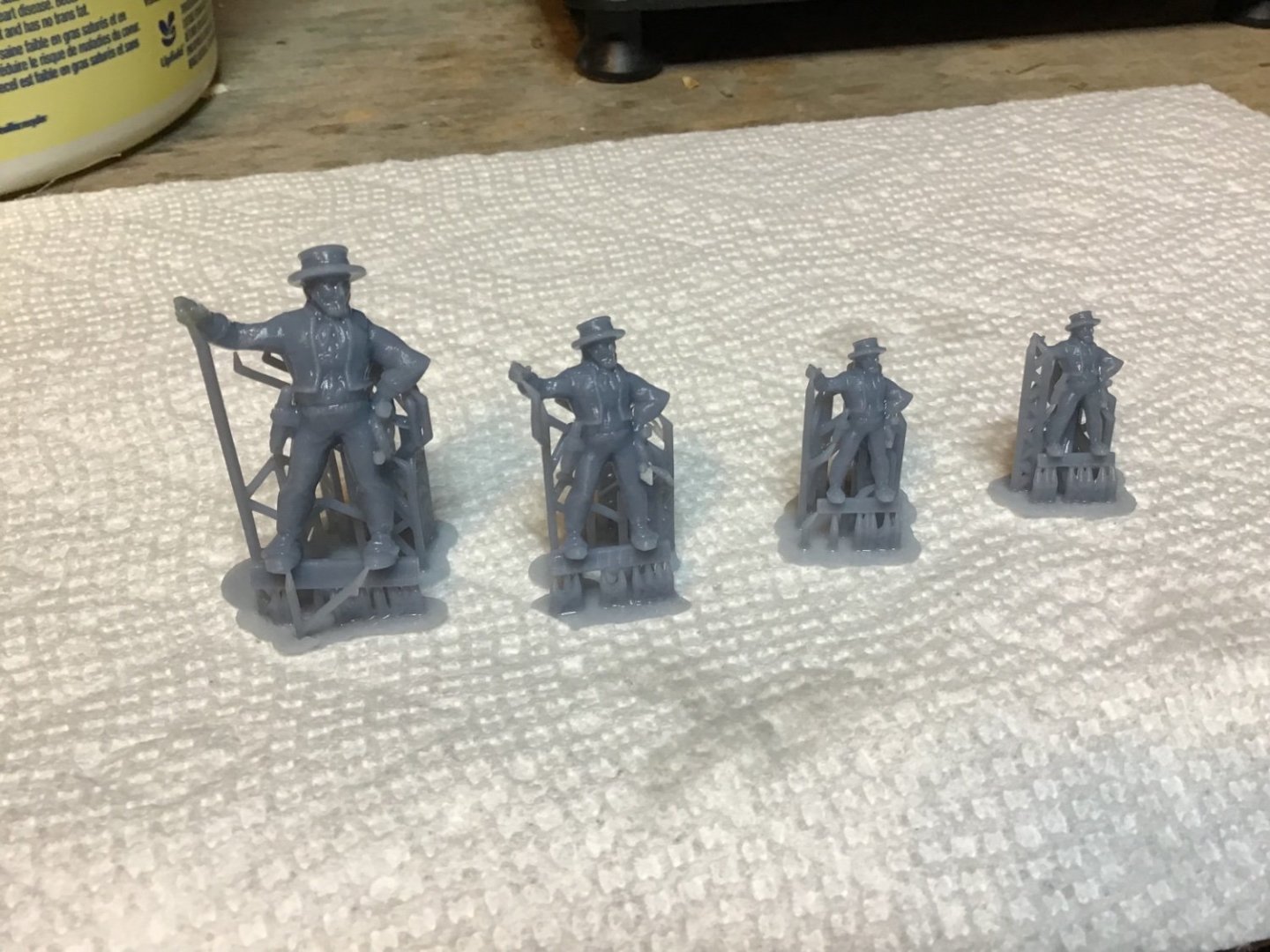
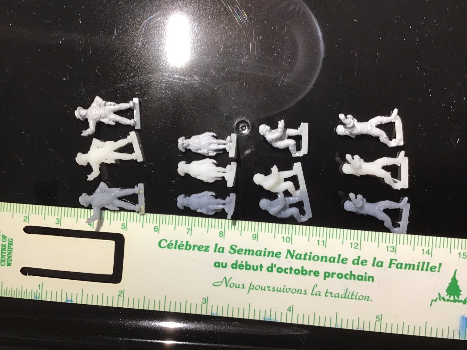
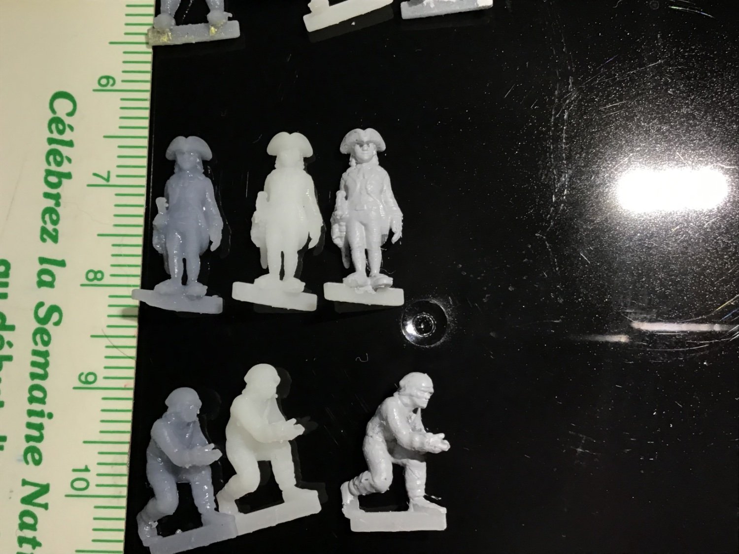
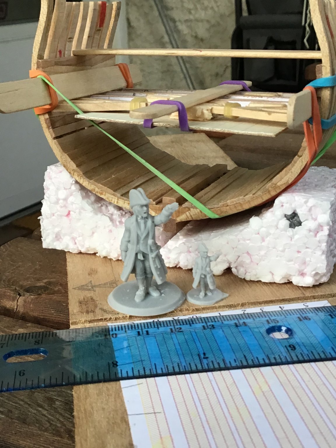
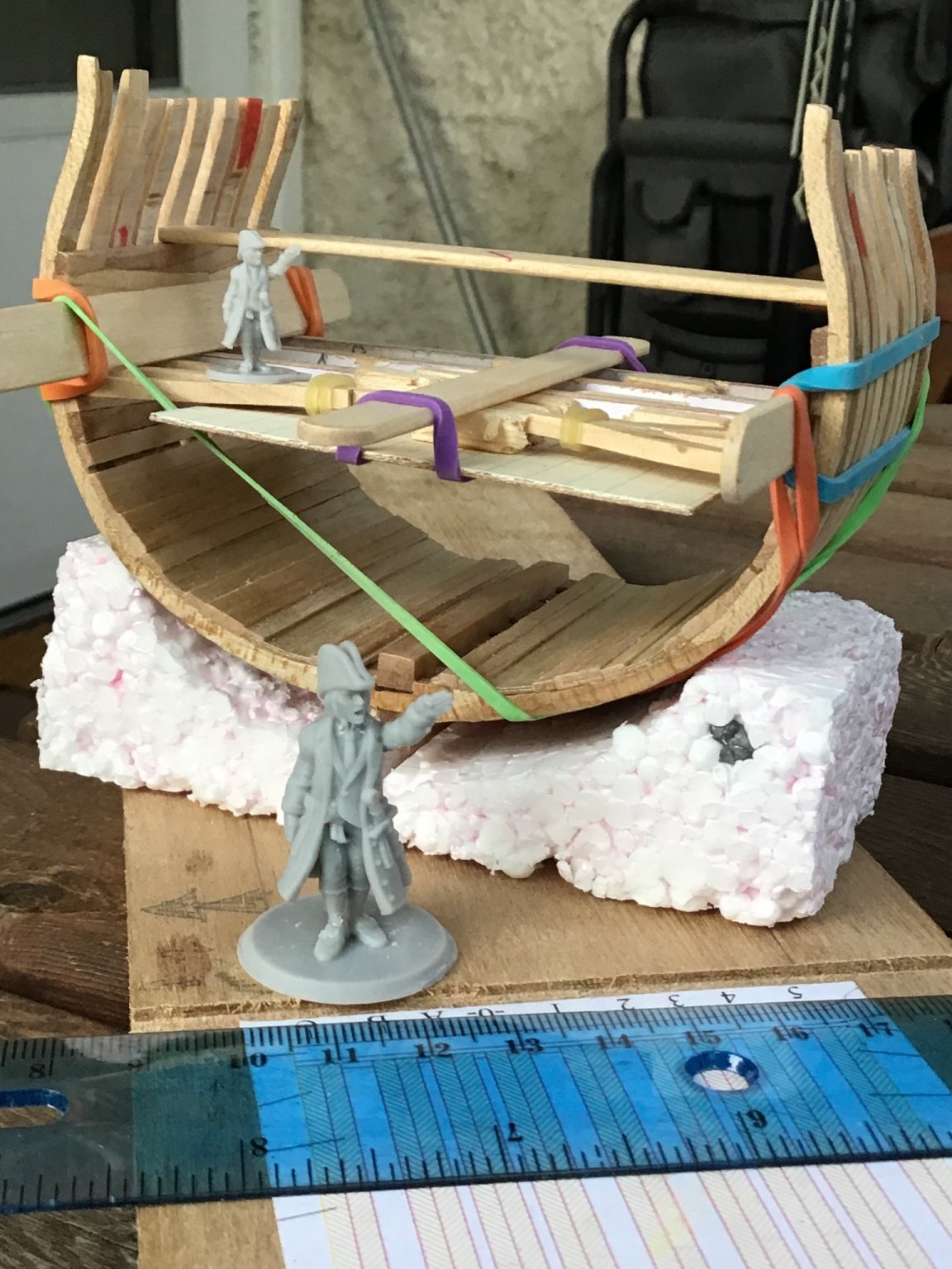
Bosun, midshipman, and two seamen in 1/96. Printed in grey and white with one primed figure to show details better:


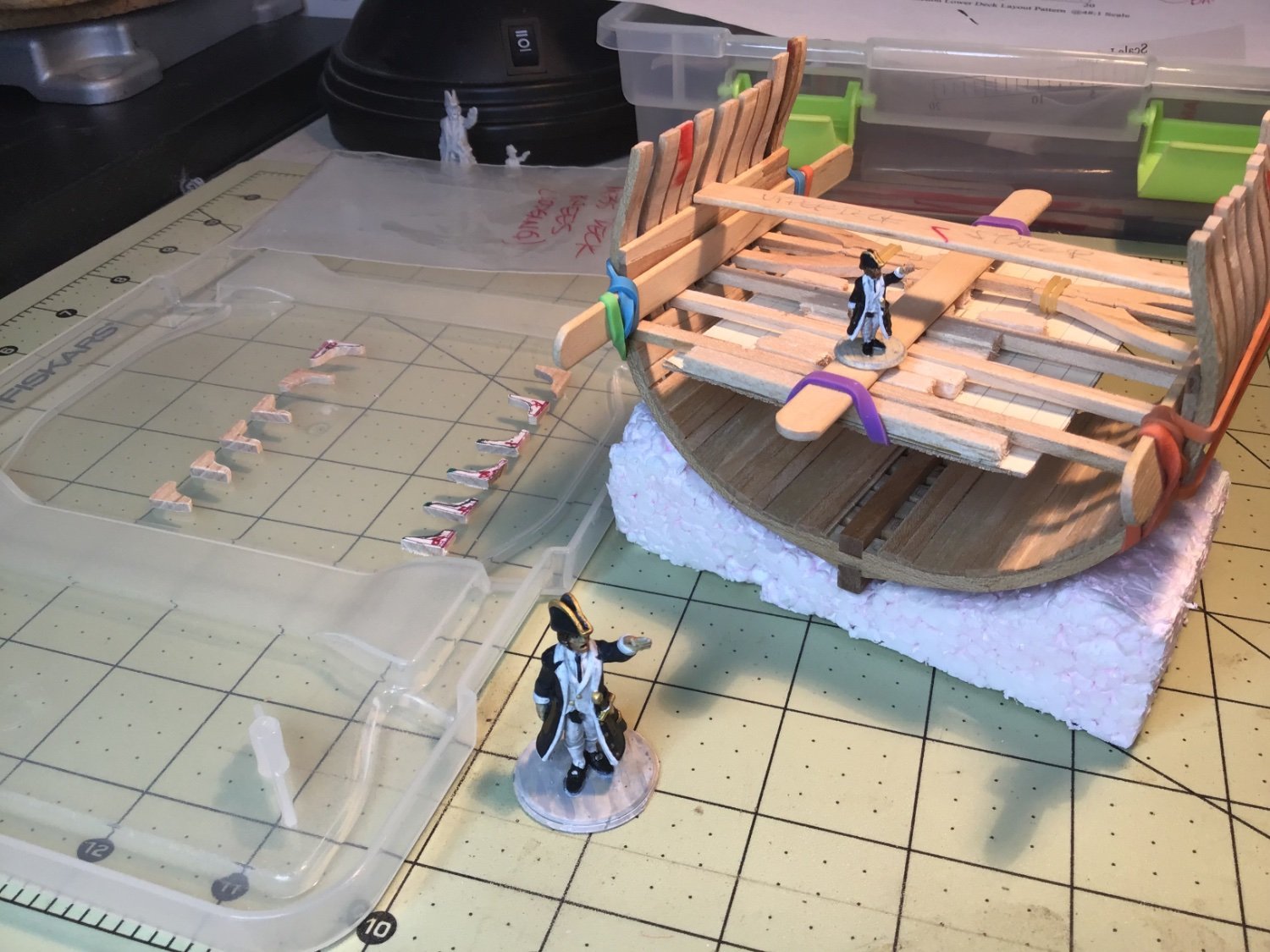
My lieutenant “Number One" in 1/48 and 1/96:
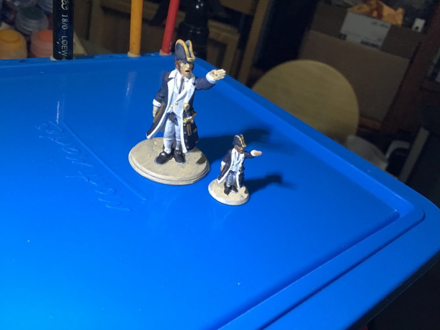
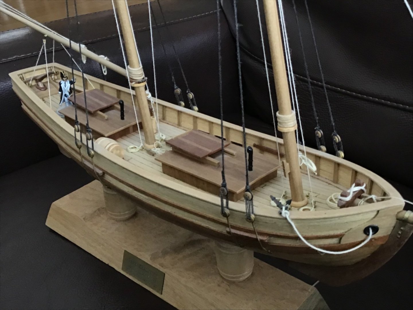
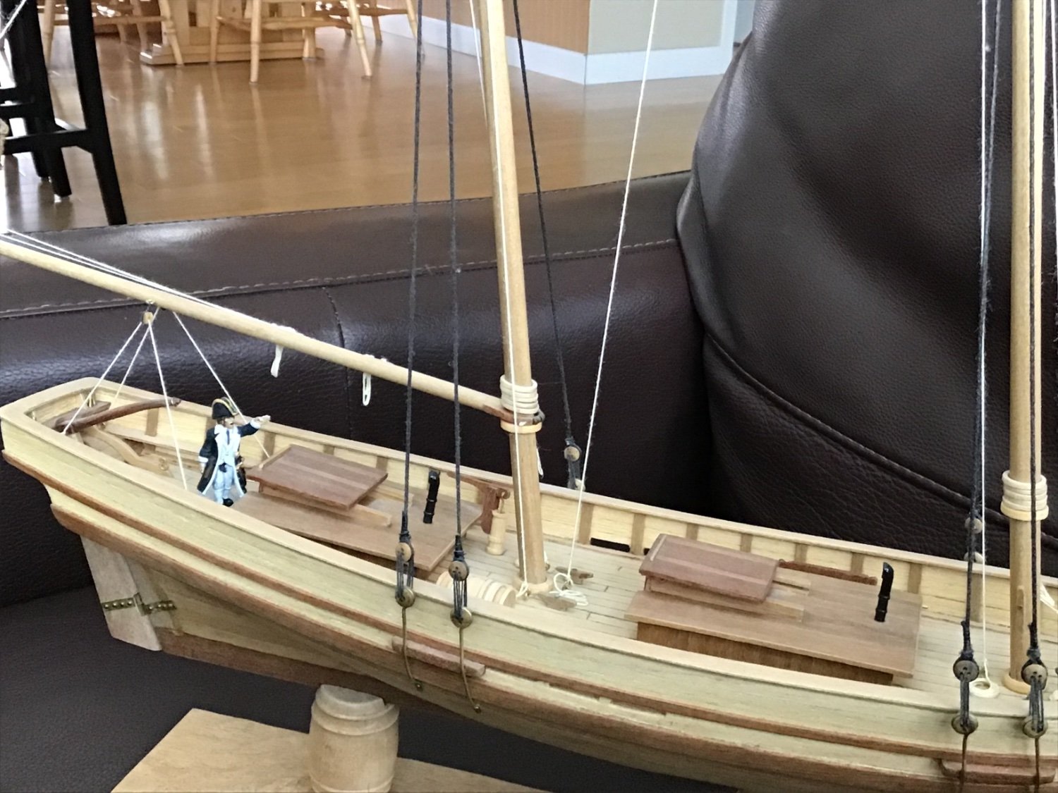
I totally agree that a figure on a model looks great. Here's my 1/50 Swift (Artesania Latina) with 1/48 "Number One” giving orders.

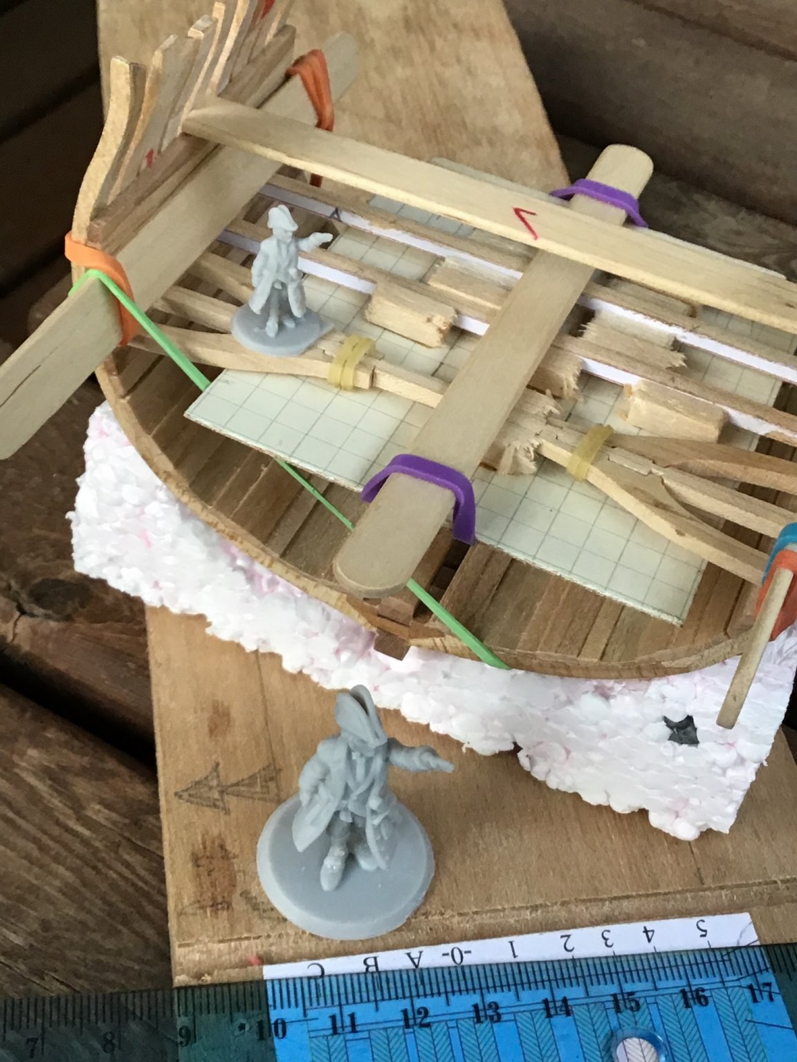
Number One and Mini Number One and my 1/96 HMS Triton cross-section in progress.
Lastly, I drafted up iron ballast with the broad arrow in Fusion 360 and printed them in singles and in gangs at 1/96. Not painted yet but I had to them check out on the Triton. Many more to be added, but I can produce them fairly quickly:


Clear skies and sharp tools!

- Ryland Craze, mtaylor and Keith Black
-
1
-
 2
2
-
Wow, another couple of years has passed! I’m still waiting for all that free time that retirement was supposed to give me…
So, after two years I first had to figure out where I left off and get my brain back in the game of solving the riddle of my "micro Titan" (thanks Ray a.k.a ziled68 for the name!). After a day of reading all my past logs and advice from you folks I came to a couple decisions:
- I will need to finish the hold first: all building, painting and add-ons before building the deck.
- build the deck in place and not as a single unit off the model.
One decision I still can’t seem to make yet is to build the well like Ainars Apalais' incredible example. The shot locker is the sticky point…it would impinge on the space under the main hatch. (Funny thing: I've been thinking about this for two years and one of the things that occurred to me was to build a cutaway main mast…and I see that Ainars did exactly that! 👏🏼)
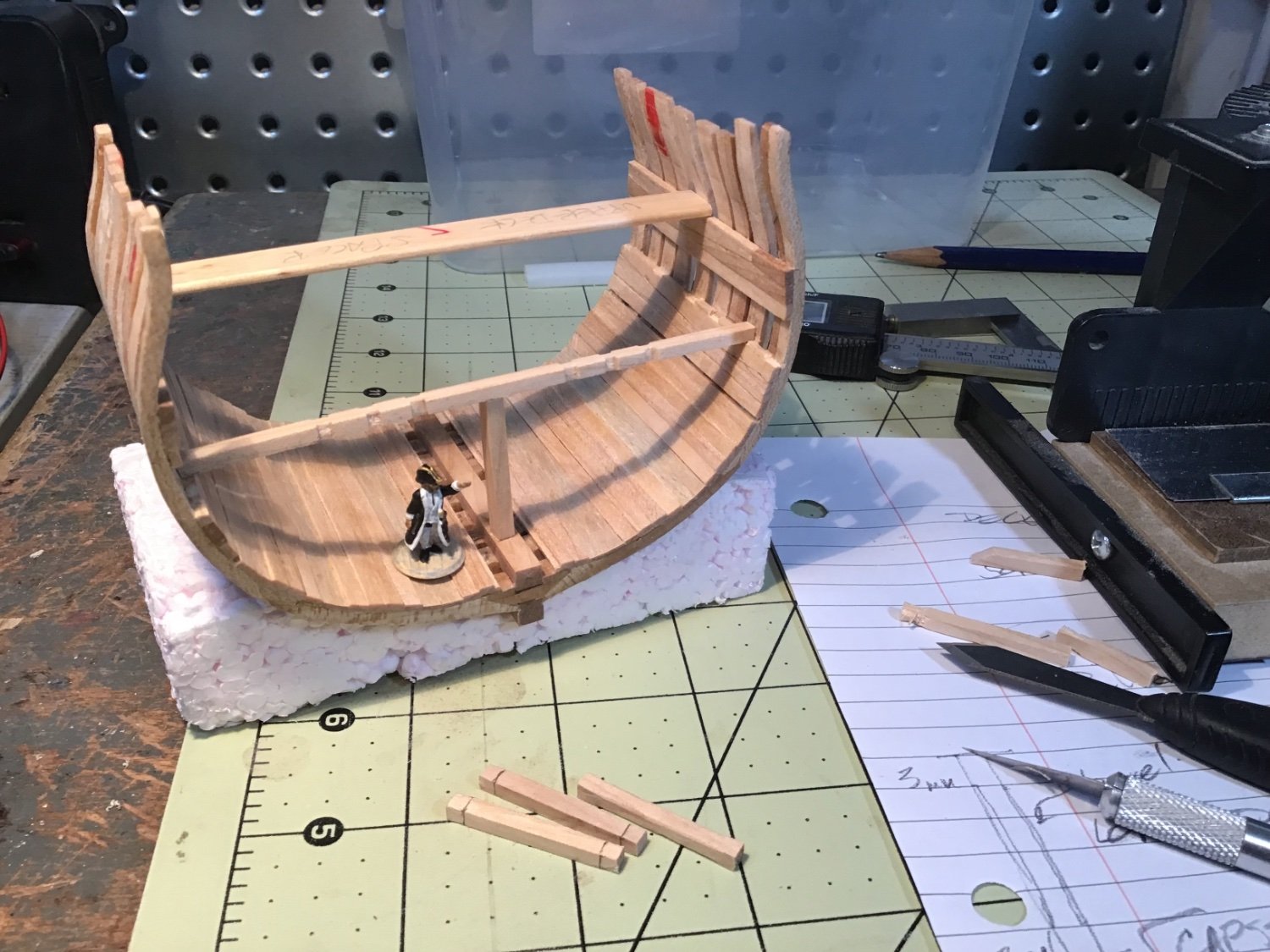
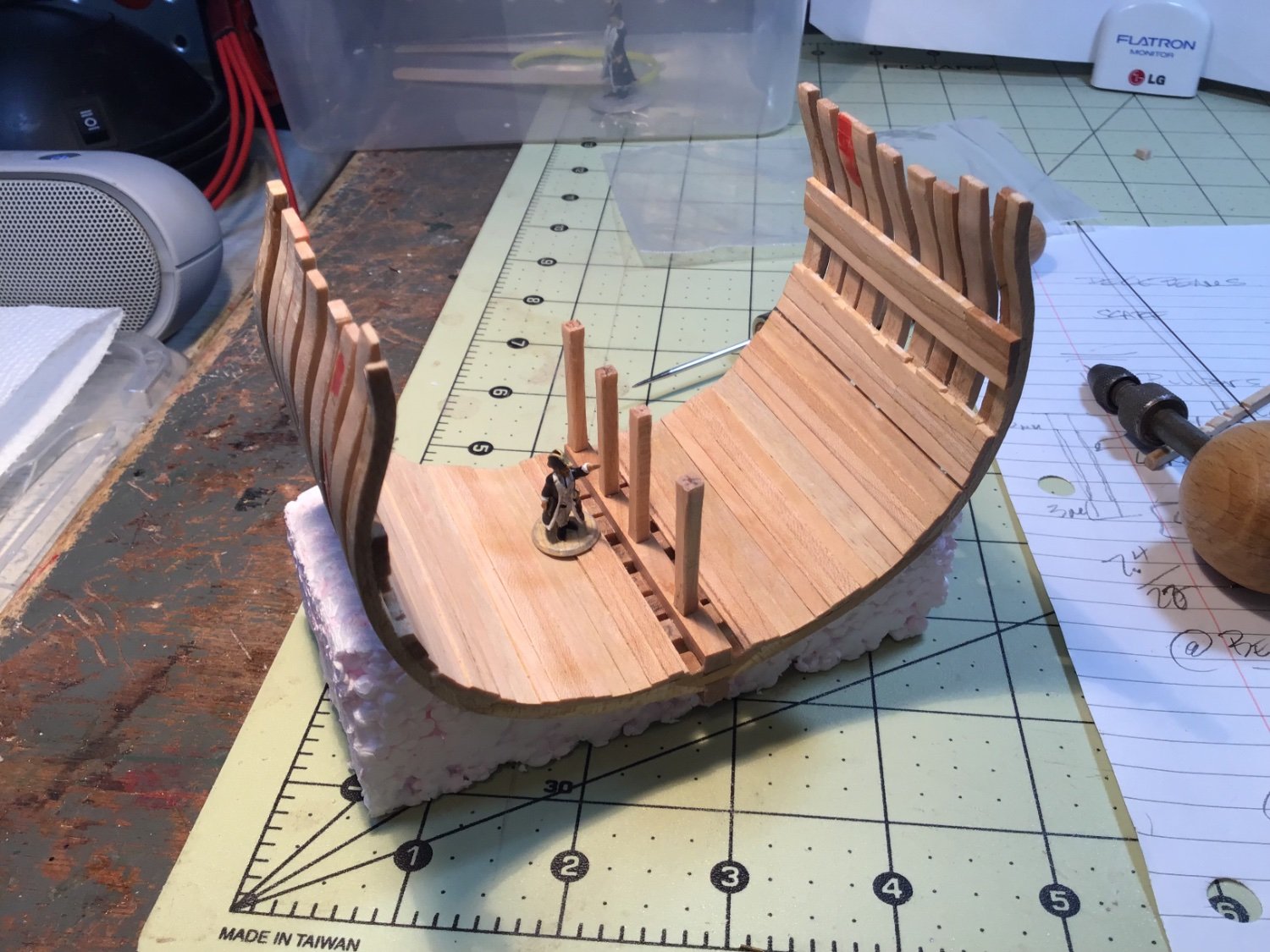
So, I set aside building the mess deck and started on pillars:
I cut some 3.3mm square stock from birch and, after cutting to length, I used a knife to chamfer the middle 80% of the corners. I based this on Anatomy of the Ship: The Frigate Diana and a photo of the hold of HMS Trincomalee.
Pillars in these ships were put in place with square tenons but I opted to use registration pins. So, I marked the centres on the ends of the pillars and drilled holes for brass wire. I the marked out where on the keelson the pillars were centred and drilled a corresponding hole. It didn’t take long to cut short lengths of brass wire and dry fit the pillars. I need to do some more preparations in the hold before I glue these in place.

And may I introduce “Number One” - a figurine I designed on Heroforge.com and printed at 1/96 scale on my Elegoo Mars resin printer. (Another reason I haven’t been building the Triton. I'll be posting about this in another topic shortly.)
Good to be back in the shipyard!
- Edwardkenway, Knocklouder, bruce d and 1 other
-
3
-
1
-
Back from the cottage and I printed off a 1/96 version of my Hero Forge figure. It took only a few minutes to rescale the original in the Chitubox software that the Elegoo printer uses. I did increase the resolution as well. Now it’s more in line with my "micro" HMS Triton cross-section in progress (please pardon the jig I have currently attached). Also, when I created the figure I didn’t pay attention to my options for the base, some of which would have been much easier to cut off when the time comes.
I've got a few more software tools I'm going to explore to create more poses and ratings and get back to you folks.
Clear skies!
- Gabe


- Keith Black, Ryland Craze, mtaylor and 7 others
-
10
.jpg.6550618ed2ebc6586f27671cced33a63.jpg)
.jpg.8b2856b6b0e880bed4e1582e9e797eaf.jpg)


Pinta by Knocklouder - FINISHED - Amati - 1:65
in - Kit subjects built Up to and including 1500 AD
Posted
Bob,
You've got it wrong...you might be the captain but you're NOT in charge! You've always got the admiralty above you! 🤣
And, just remember Mark Taylor's signature:
Clear skies and sharp tools,
Gabe
(Captain, NOT Admiral)🤣