


Matrim
-
Posts
1,401 -
Joined
-
Last visited
Content Type
Profiles
Forums
Gallery
Events
Posts posted by Matrim
-
-
Interesting concept though i don't think it is doable. Perhaps for modern plans with no 'give' but for anything on old paper you have to spend a lot of time making certain the plans tie up to each other correctly even before you get to drawing the frames.
The other problem is more specific and directly related to the taper quote. We do not have a definitive way of doing these things and my way is almost certainly a fudge. When build plans are made you spend a lot of time deciding how much detail you want to put in and there are always tradefoffs between realism, ability to draw in scale and time.
-
-
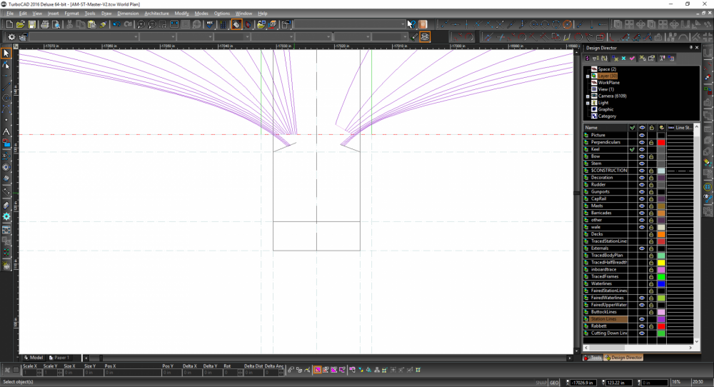
Indeed as these plans dont have it.. (most of the plans posted in detail are missing something) though in this case that is less an attempt to deliberately lose something as a decision not made. Basically when I last looked at building on the original plans I had decided to taper after completing the stem and false keel under the perhaps mistaken idea that it would be easier.
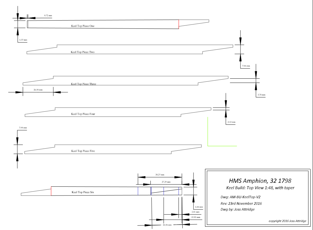
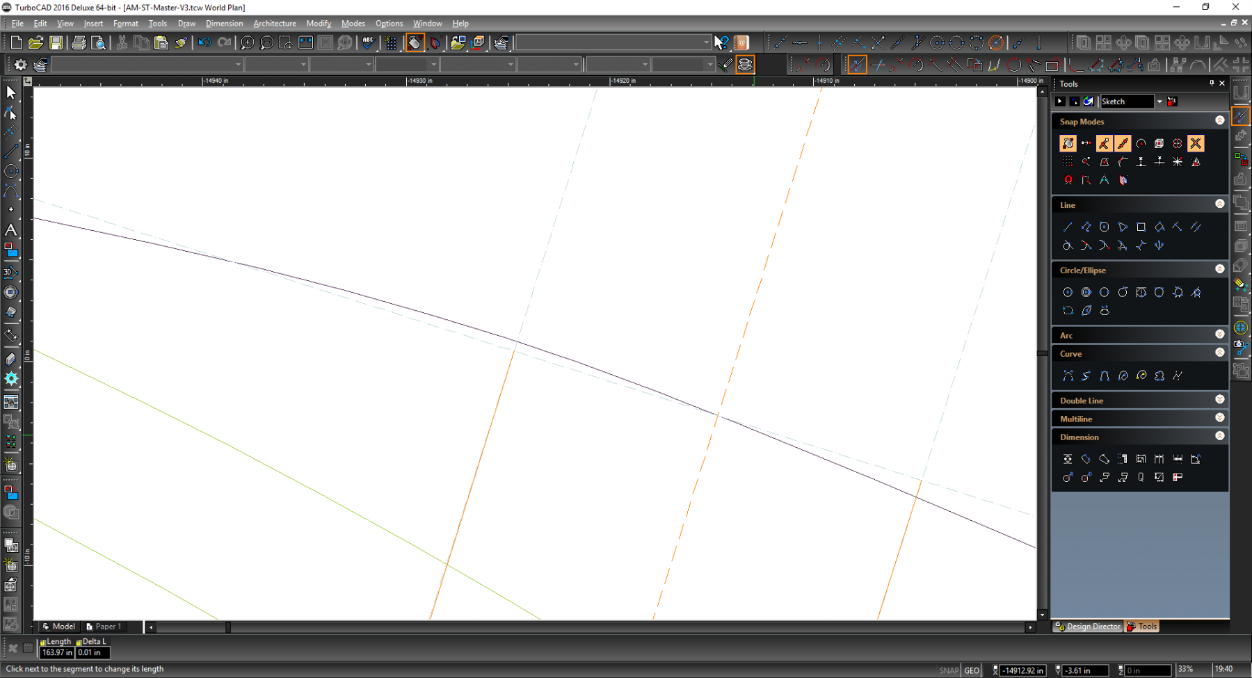
Perhaps it would be better to mark the taper now and cut it accurately on all pieces..
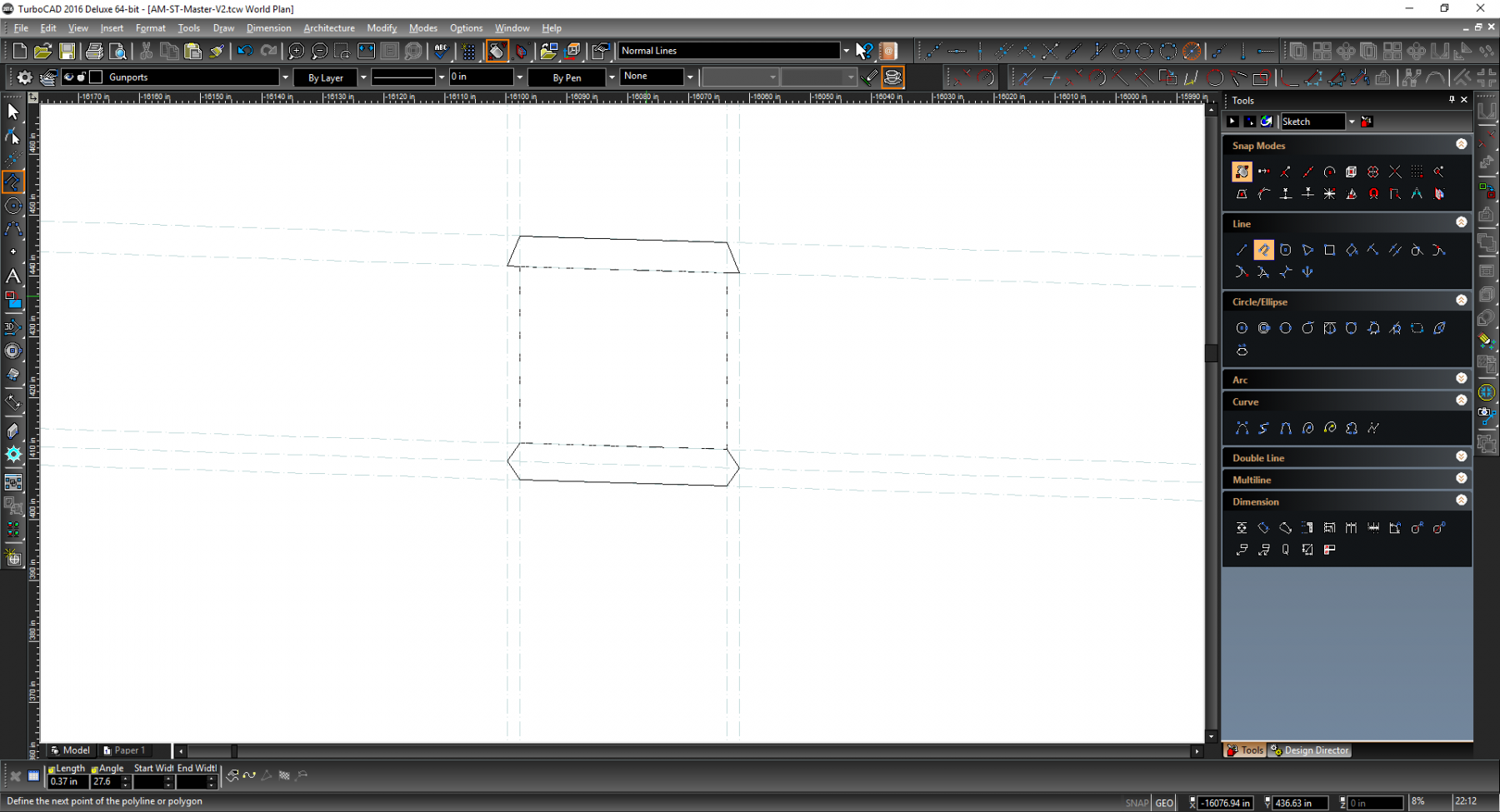
Just in case here is a revised with the start of the taper marked with a red vertical line...I am cutting corners slightly by making it start just after the joint (in both cases) so if this is very wrong then please say!

-
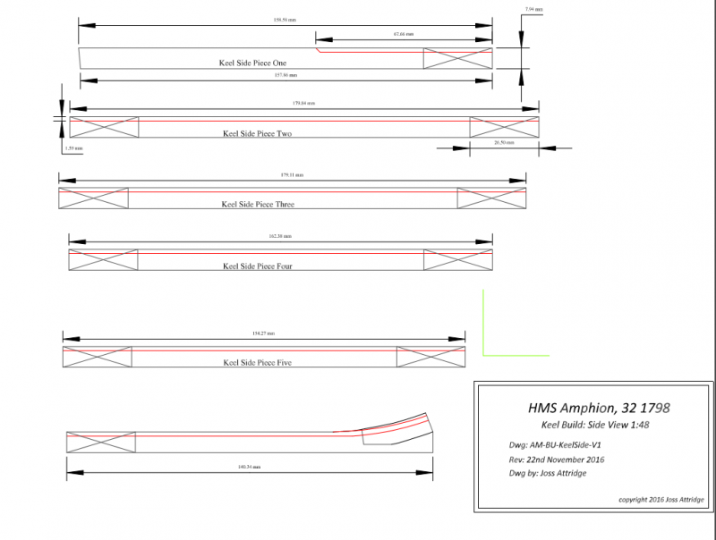
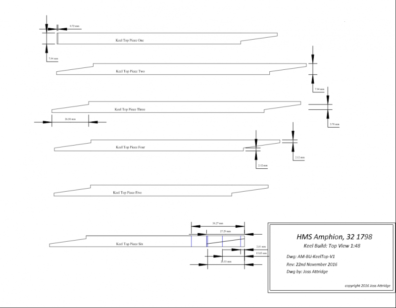
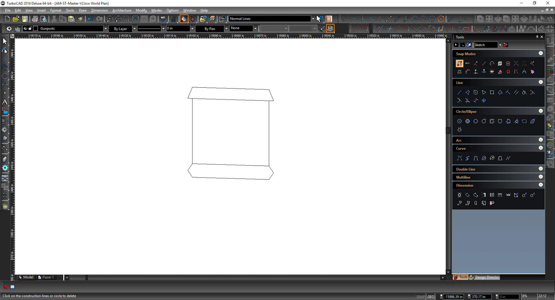
Another (slow) update. I have started on some build plans. The following are provisionally measured at 1:48 scale though this may be adjusted later after more consideration.
We have two keel build plans. The first showing the side
and the second the top
The False Keel will be an easy addition along the same lines then I will probably move to the stem plans. You will notice the first plan has a 'green L'. I tend to add these to build plans at the correct scale so 1:1 those two lines each measure 48 inches in this case. When printing I can then measure those lines and they should be exactly on 1 inch. If so then no problems with scaling has occurred..
-
You might be better of posting a topic in the cad forum as you may have more chance of reaching someone who uses turbocad with the mac.
Also try posting in the turbocad forums. Again you are more likely to find a mac user there and the forums are generally more responsive than contacting the company.
-
I agree. I am using (currently) 2016 Deluxe and tend to upgrade every other year.
I also load the image in and then manually trace (it is surprisingly enjoyable). One thing I did have to do was to switch off the red dot graphics thingy that seems to default as it made the imported plan image 'fuzzy' when drilling in (which is really not good for tracing) BUT that was on a windows machine so may well not be relevent..
- mtaylor and aviaamator
-
 2
2
-
Seems sensible so I have added them on (0n the frames themselves but below where the keel and supporting wood will go once building starts). It does beg the rather irrelevant question of 'what did they name the two single frames between ( ( B )and B?
So on the plan moving out from the (0) central frame I have
(0) double
(Al)
(Ar)
( B ) double
?
?
B double
Cl
Cr
D double
and on
For the moment I am using B-l and B-R but I did wonder if there was a correct naming convention ( admittedly a question of spectacular unimportance)
-
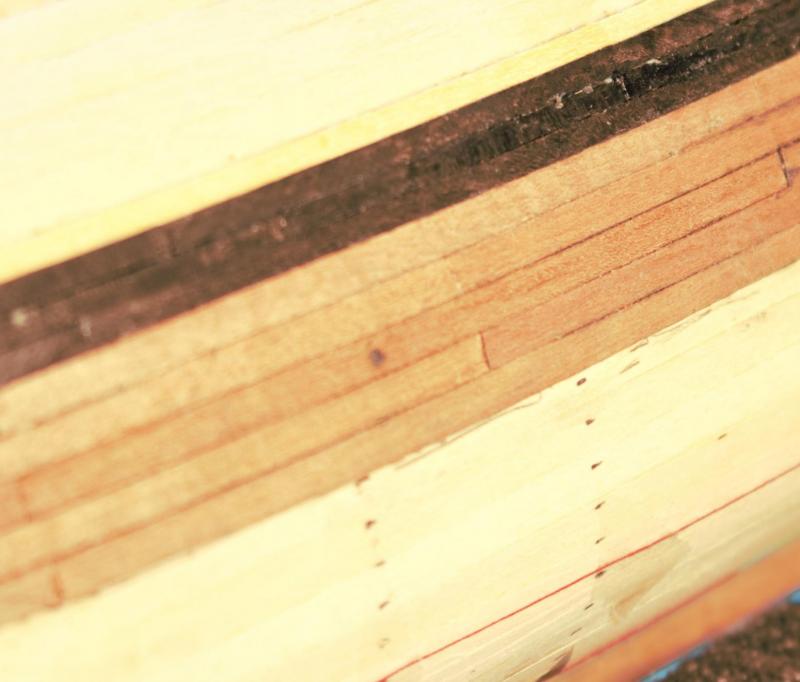
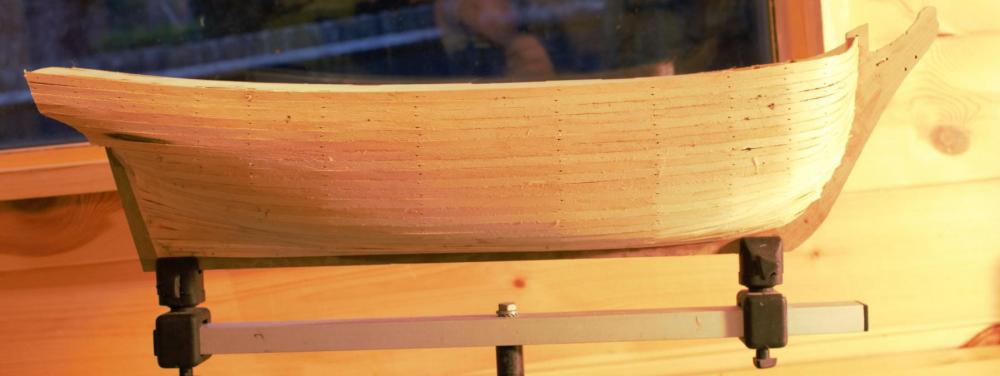
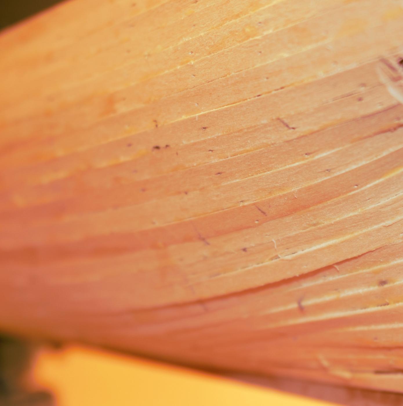
Onto the outer layer of planking, which is doing its normal magnificent job of showing just how much vast improvement I still need.
I started with the wale which (contrary to the instructions) I planked straight onto the first layer using ebony. I have fairly restrictive practices with regards to this wood. These are never to saw in an enclosed area (I took my table saw outside and cut strips there whilst masked) and don't sand if I can get away with cutting. This is mainly to reduce risk from what is a nasty wood healthwise.
Anyway its not only nasty health wise its also not easy to work. Therefore I did reduce myself to soaking planks for 12 hours before bending. Still I did manage to get through it.
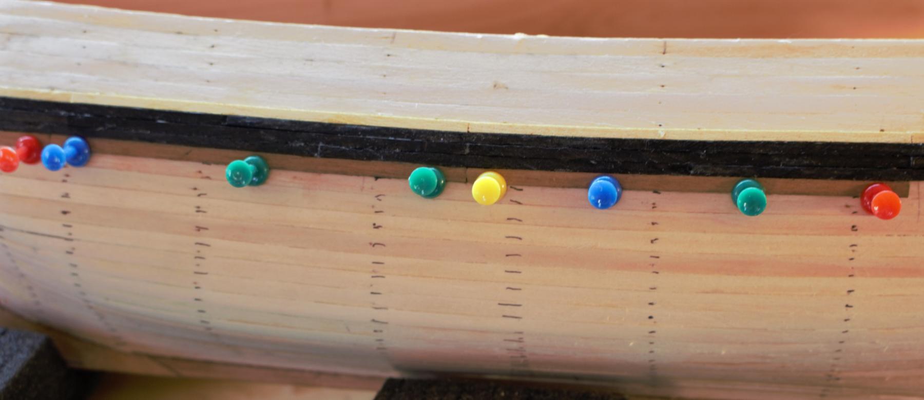
For the standard planking I endeavoured to improve my technique. I attempted to tick mark out the required planks if only to allow me to place string battens to get an eye for the run. Once this was done I mainly ignored them and instead switched to using those fancy compass things. On these you set the amount of planks in a section (5 for my first 3) then measure the gap between the batten line and the upper line with one end and the other end gives you the correct size of plank. This is only needed for the front planks at this early stage but is repeated for each hopefully avoiding incremental errors in the tick marking or anything else.
A shaped plank
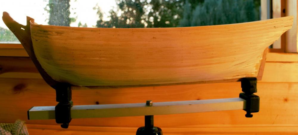
Once I have my plank cut to the correct angle I now try and bend the side angle with some clamps and a hairdryer and then start using an amati planking strip bender (my new favourite planking tool!) which can cope with curves in two angles. The upper corner is removed with an abrasive and the bottom side covered wwith black pencil. I then glue in. I am still a creature of habit though and use wood glue and superglue. I usually smear the wood glue in three sections on the plank and then along the top. Super glue then gets touched at both ends and the middle. I then position the plank using pins pushed through the under plank layer (not the outer plank layer). Which do a nice job of holding the plank tight against the parent whilst it dries.

The pins in operation
Each evening I usually manage to get through one full planking strip before finishing.
Now I am a lot happier with the results but am still falling far short of what I would like it to be. I feel that my shaping at the ends introduced slight crescents (as a plank in a gentle V meeting another plank also V ing can cause a slight gap. But nothing that is not repairable in the sanding stage (where I tend to fill any gaps with glue and sand over them). It is also noticeable how the side I started first is not quite as good as the second side.
Anyway its nice and relaxing and when I get around to my full scratch I will be a lot happier at planking now. Finally I am using a rather ugly two split end planking system. I would be highly unsurprised if it should be a three or more split but this is a step up from my last kits no split end system so hurrah for me..
Status so far - this is the first group of 5 planks and you can see the thread for the next batten at the bottom of the picture. You'll also notice that my tick marks are also slightly out something I put down ot the removing of the corner shrinking each plank slightly as at this point the planks were all left full width..
-
-
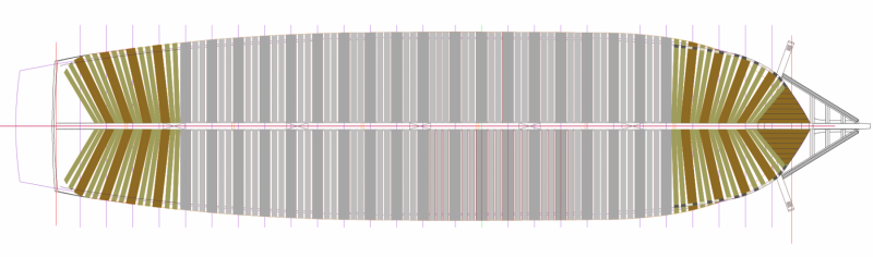
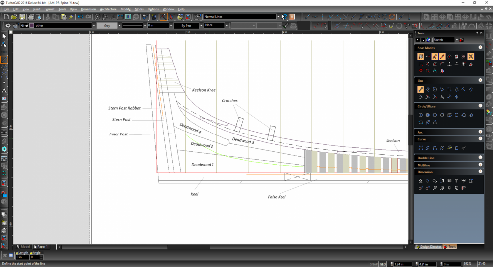
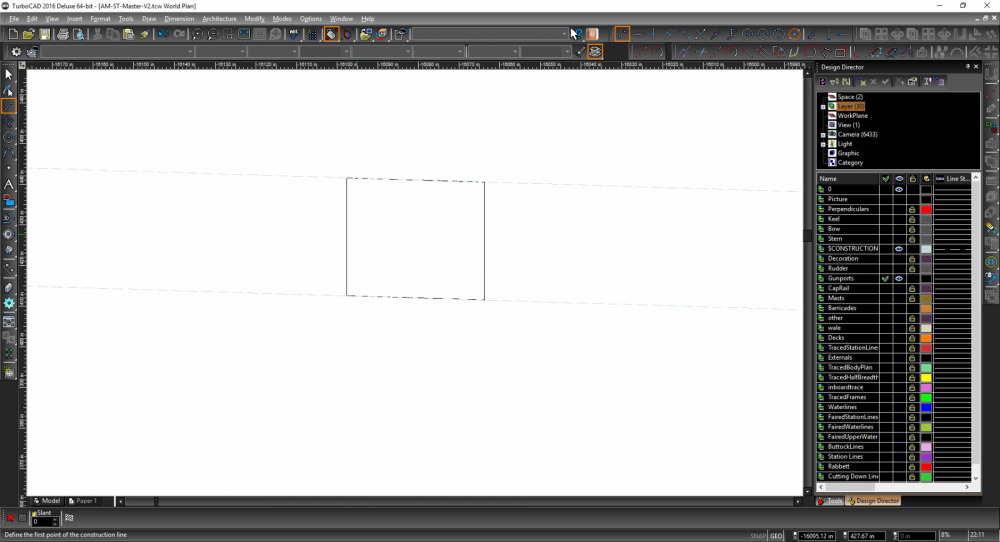
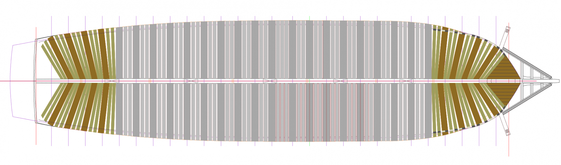
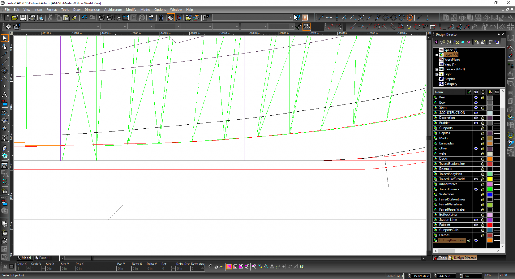
K next up we have my fish plan (or the gangway overhead frames plan if you have no poetry). This is almost the key starting plan as it shall be printed full scale size (well in scale sections), laminated, then glued to the building board.
In certain respects I have simplified it somewhat in that I have not completed all the relevant hawse piece details (mainly as I am still considering re-work there) or added much stern structure detail beyond the outline. Both these areas will be worked on against the master as and when I need them so may be added to a version two of this plan which would provide more structural detail than the building board would need. I also decided to not add the station numbers as they don't have much use for this plan.
Additions that did not exist in the last are more details on the rising wood and the keel/false keel seperators. I found in my earlier look at building that I found it difficult to ascertain the correct overall size of those pieces as I did not have a single plan with 'all' the keel on. Since this plan is the total size it makes sense for that information to be on here so it should assist with building the keel/false keel/rising wood beyond its usual main purpose of assisting in frame layout and size generally.
Finally I might switch the scale of this I was originally going to keep to 1:60 but might drop to 1:50. I don't plan on including the top gallants, the masts will be angled to catch the wind (reducing height and width of the end model) and the extra size will help make some of the bits like the rising wood much less fiddly when I get round to them. Not decided either way yet though.
-
-
Good point as they dont! I usually take the cant frames from the keel so that the curve, when it hits the ledge, has a smoother curve (I found it appeared disjointed slightly when started from the ledge which may just be the way I was drafting it) therefore It looks like I forgot to trim...
Revision one incoming quickly..
-
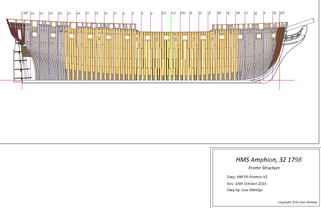
Time for another presentation plan. This one is for the frames so not particularly exciting plus I a may re-work the hawse pieces as their is something there I am not quite happy with, the full plans go into some interesting fiddly work that I have not decided whether to reproduce or not.
After this comes the building board plan or the 'fishbones' as I like to see it, which is possibly the most useful of the large plans. After that I may churn out the individual build plans for the central section of the ships spine - keel, false keel, stem and apron etc.

- mtaylor, aviaamator, trippwj and 4 others
-
7
-
If it is a double plank kit then dont worry about it. All the under layer does is to supply a better 'shape' for the final layer to sit on and you will sand away any bumps. Use it as a 'practice' as to what works and what does not so that when you get to final planking you will then do a much better job.
If you have a look at my first layer of planking on my Bounty (steel yourself it is not pretty) and you will see nothing that belongs on a final model...
http://modelshipworld.com/index.php/topic/13783-bounty-by-matrim-caldercraft-164/
- Dutchman, Overworked724 and Elijah
-
3
-
-
Thanks for the compliment though a lot of others do 'better' plans than I do.
I am actually at a point now where I could start building of the plans (I should really do an update though will probably wait until I get the frame master out) as I may avoid doing the individual frames until I need them. It took avery long time to get little individual pieces out of the way last time so I will have time during the build itself.
I had not thought about releasing them plus would need to complete the model to be confident the plans were good enough for the same (and that is a looong time away)..
-
-
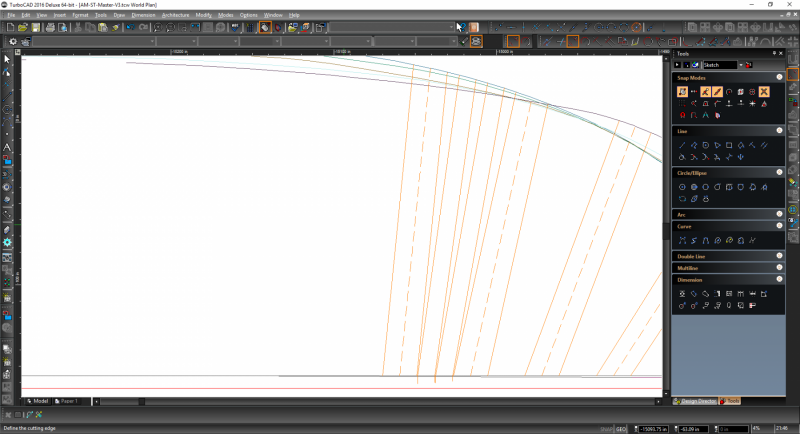
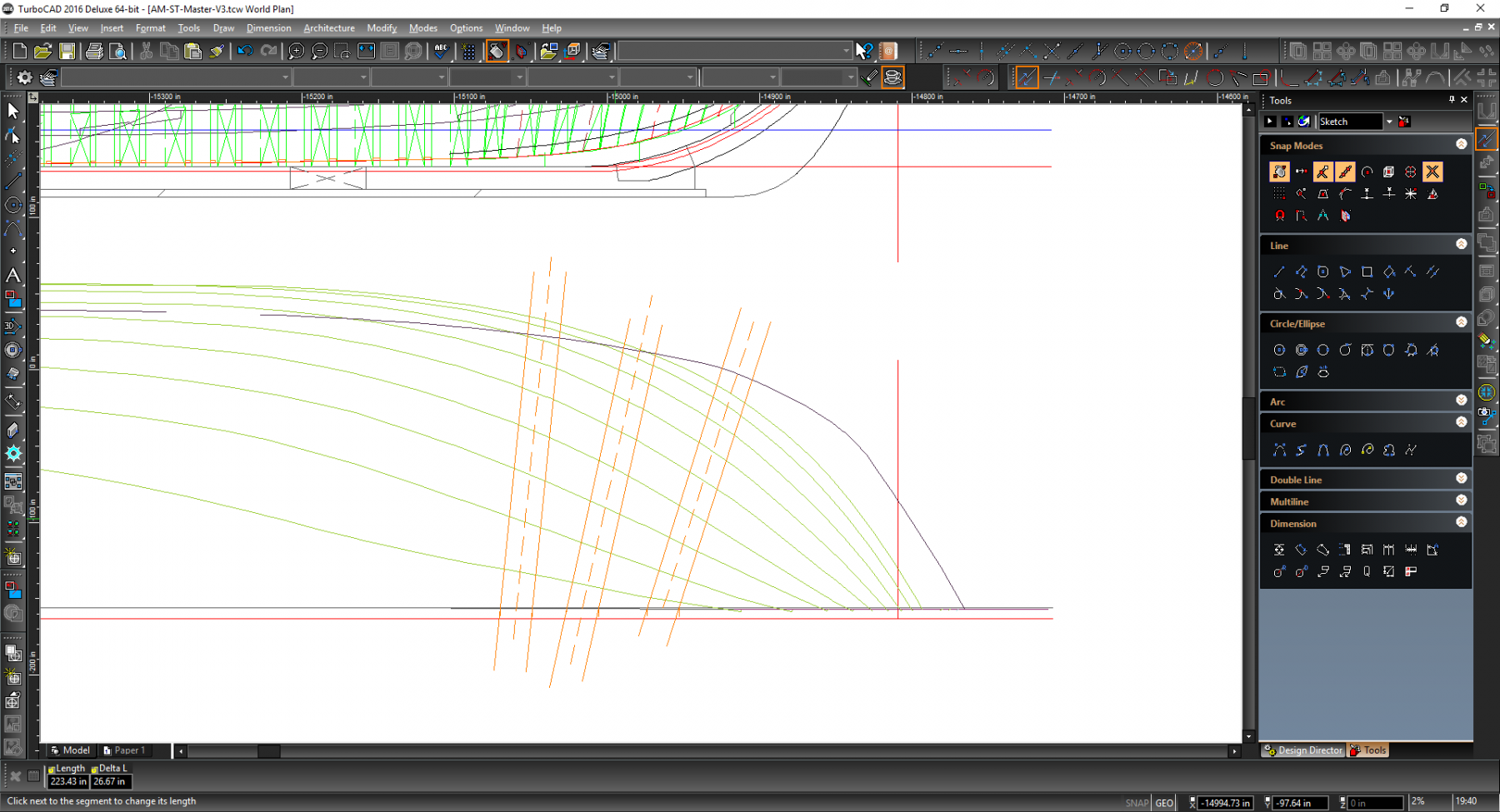
Time for another terribly unexciting update. I have now started on the forward cant frames and after some abortive attempts finally managed a process which I was happy with.
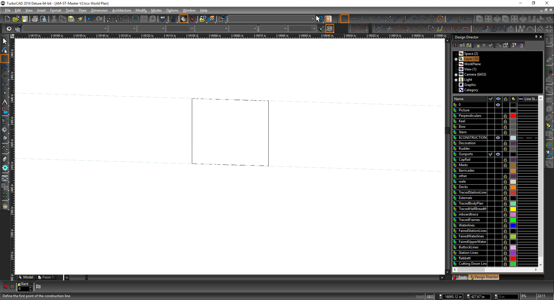
Initially I used the traced frames as a starter (the central dashed lines of the double frames). I took a vertical construction line from the lowest visible waterline to the keel and repeated for (usually) the cap rail. Joined the two together and then extended to get my four center points.

I could then place a vertical where it split the keel and added two parallel lines 10.5 apart.
I then added little temporary lines where these broke the keel line.
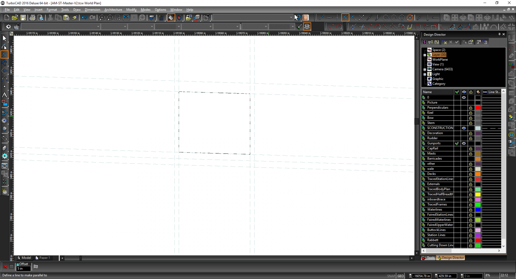
Next I moved to the cap rail and added a line perpendicular central line where it broke the cap rail.I could then add two more perpendicular lines also at 10.5
Now I could join the little temp lines on the keel to the equivalent end points on the construction line (not the cap rail as that would move the lines out of sync)
Now I extended to new lines so they stretched far beyond all waterlines

The next job is to add the filler frames. For this I measured the gap between the relevant double frames

Deducted 21 for the frames themselves, divided what was left by 3 and then added construction lines of that length, then 10.5 either side and then added my helper lines so I could remove the constructions
The process at the cap rail was similar except here I started by drawing a construction line between the two double frames and used that to right angle my working construction lines
before adding the lines as before, extending and eventually trimming
Eventually I completed the lot. The singles at the end followed the same approach but with less gaps as the far edge was the edge of the last single frame and for the singles closet to the square frames I used my last 'new' frame as the start point but followed essentially the same process
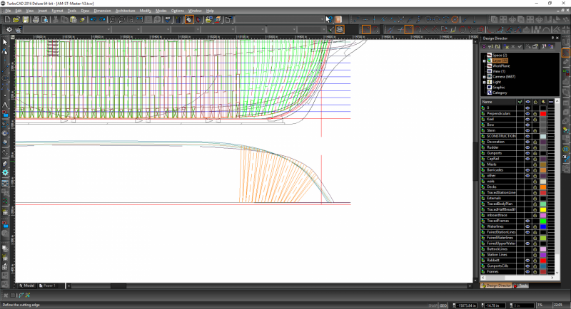
Now I could move onto drawing the frames themselves. This followed the 'usual' approach. Vertical constructions through each point (starting from the keel as that makes a nicer line even though that section will eventually get chopped off)
Repeat for upper waterlines and then join in

This will keep me busy for a bit and the same process will be followed for the stern cant frames.
-
-
Hi,
On my Bounty the kit uses double planking (fine) but seems to want to second plank before applying a third level fo planking for the wales. I would prefer to add the wales as one entity (and not on top of the second planking) but am not certain if that will damage things at the stern especially as the AOTS seems to show the wale sitting on top of planking..which is weird..
-
One of the inumerable ship boks I purchased when I first started modelling stated 'everyone should plank at least one ship, as it teaches humility' (then again it could have been a sig on msw).
I always remember that because I really suck at planking. This time I did a better job than usual and the flatter bits look quite nice. Since I am soaking the wood and letting them dry on model the bendy bits sometimes have a tendency to perform extreme shape movements overnight resulted in less decent planking. Fortunately this is the first layer so it will all get sanded to death without to many woes.
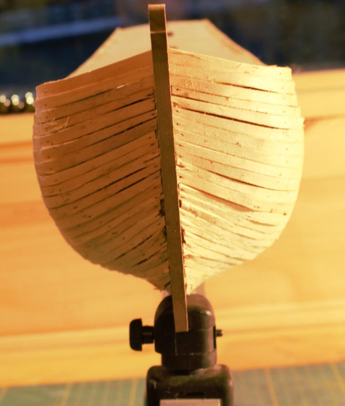
So prior to sanding we have
looks nice, but look at the front

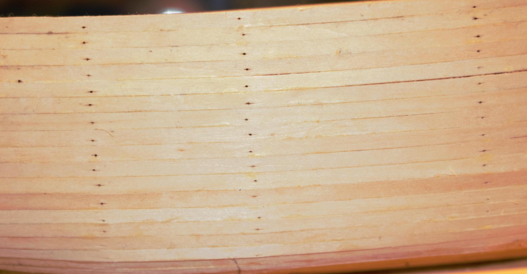
blurrrk. I shall calm myself with a close up of the side

and then shoot myself by repeating this at the front

They say a picture never lies, these pictures are not only not lying they are holding up insulting placards and laughing.
Anyway a not so hard sand on the sides
and a harder sand at anything with a curve (that sticky out plank is actually slightly unglued and moves in and out when pressed so I gave up attempting to sand something that happily moved out of the way whenever I applied pressure)

Means I am almost ready to mark the wale on. I shall probably carry on sanding the front and rear as I am not quite happy with those..
-
Carrying on my 'repeat everything I did last time' process I have now finished the square frames, added the rising wood and completed the Centerline presentation plan.
I was extra careful ( more careful? I dont want to over egg the pudding) with the rising wood as it was uncertainty concerning the Bearding Line that stopped my build and pushed me back the drawing board (drawing pc? we need new words..)
Anyway once I had drawn it in and notched the wrong side (doh!) I then re-checked the base line against my original traced frame plan which I had cunningly not removed and left invisible in case of need - just to apply a sanity check on the line.
Here is it... I have temporarilly made the bearding line red (it is usually light green which is the same colour as the original plan frame trace)
As can be seen the line is very close to the original so I am pleased things match up.
The centerline plan ( as before) is loosely (closely) based on EdTs wonderful draftmanship though not as advanced..
Here is the front

And here is the rear
You'll notice (well perhaps not) the orange 'turret like' line on top of the frames. That is the rising wood. Last time I left this and drew it in after drawing the frames. It makes much more sense to get this on the master plan now so it can be used to get the correct keel base when lofting the frames. I am keeping to the decision I made with the previous build to use less angles (and milling the contents) and using rather more horizontal joins that perhaps is historically accurate. I did wonder whether I should perhaps re-draw some of the angled frame joins with the same simplifying aim in mind.
Anyway next up are the cant frames and the build board plan. I may well start generating some scale build plans at that point and only loft the frames when I need them. I will have to see how confident I am when I get closer to that point.
-
I will be trying some African blackwood for a wale quite soon. I have ordered some ebony blanks as well though (I used ebony on my triton cross section and though it turned out well it was certainly quite 'splintery' )
- Landlubber Mike and mtaylor
-
2
-
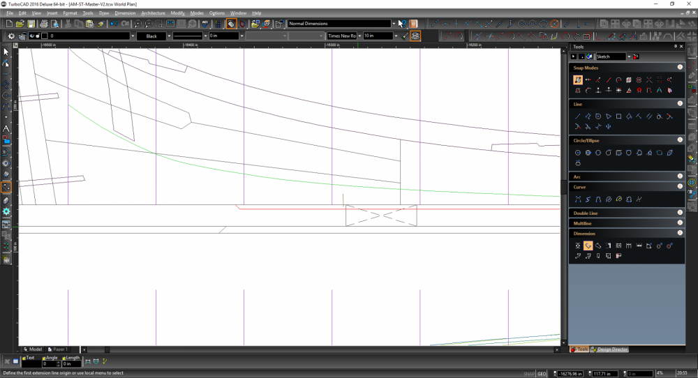
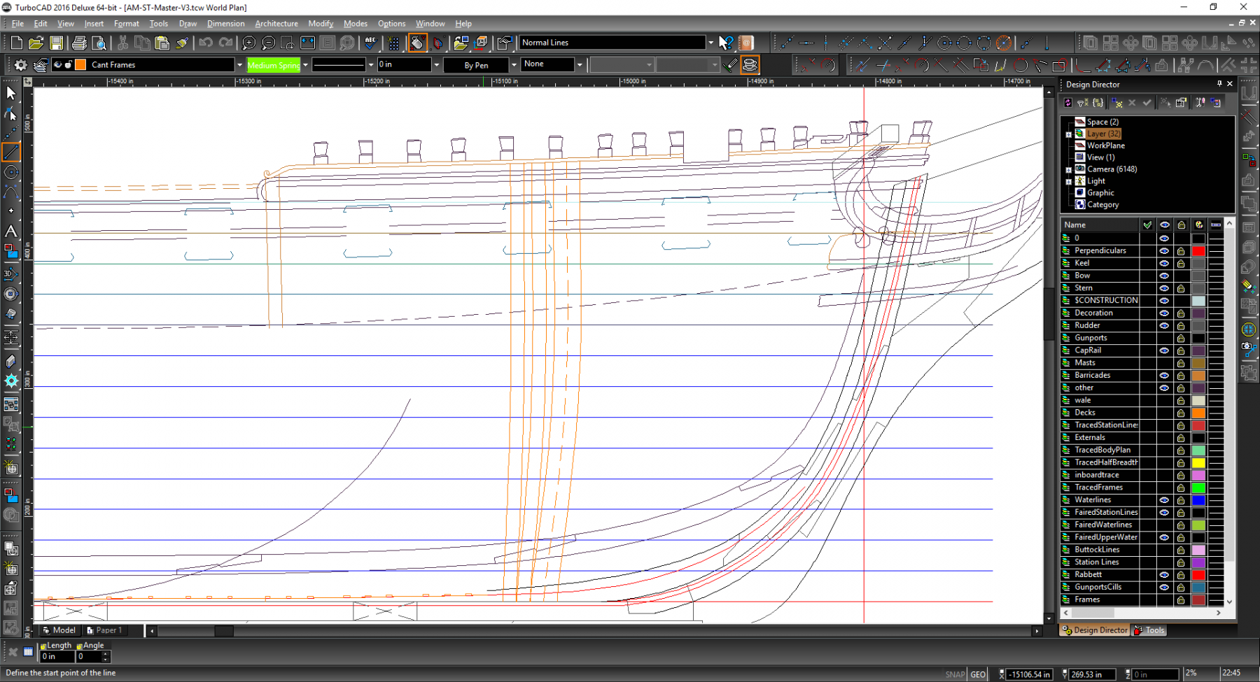
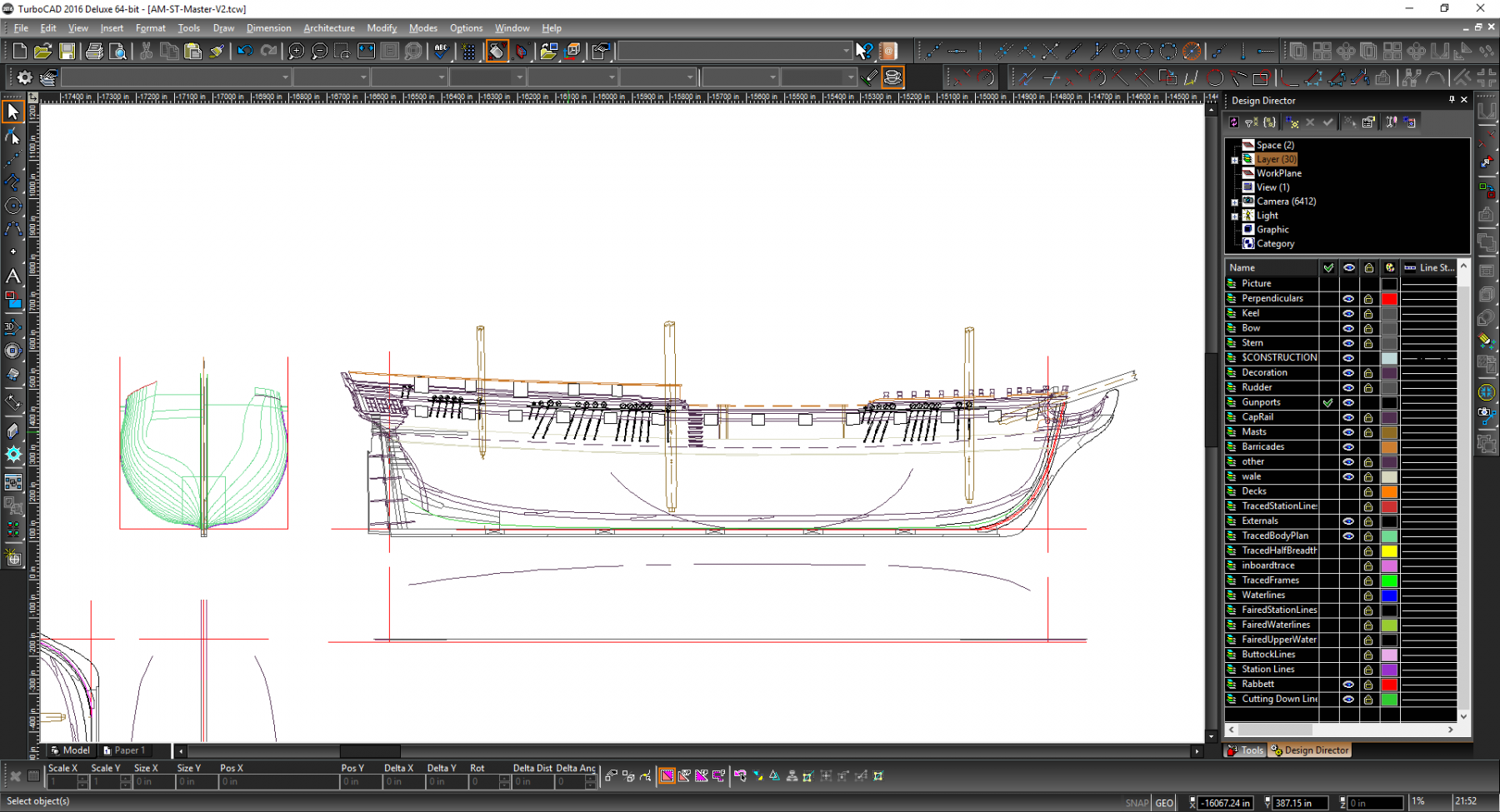
Now the lines are redrawn I have started firming up some of the other lines. The keel, rabbett and false keel were adjusted in size and the beakhead shape adjusted slightly to cope (I ended up using some of Waynes circles listed up above to get the angle looking better). Then these lines were transposed over to the body plan.
Here are the full size adjustments over the old.
and the adjusted
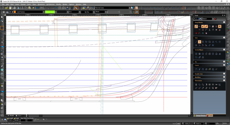
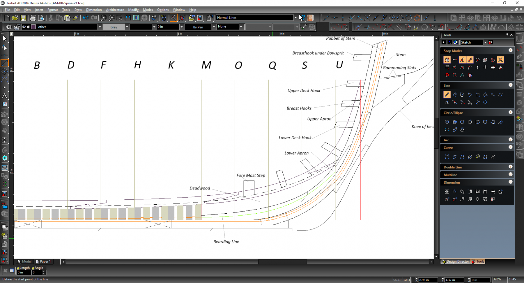
After this I drew in the new 'cutting down line',in my last research log this was covered in huge detail (or to put it another way some valiant souls spent three pages of log correcting my mistakes in understanding). Anyway this time I drew a vertical parallel line 9.5 inches either side of the centerline and copied it over the profile from that.
Here is the stern side, the cutting down line is green
My next 'major' task is to get the frames drawn in so before that I tidied up some of the joints and then corrected the gunports. As with the cutting down line I have covered this already and the basic purpose is to ensure the lines lose any angles caused by bad tracing. End result

The key being to remember the horizontal lines are not always horizontal to the keel.
With some of the rest of the ship..

Port cills were quick and easy. I decided on the gap I wanted them to stick out and the followed the following procedure.
Add angles construction lines along the top and bottom edges
Add vertical construction lines the distance I wanted them to stick out

Add a parallel construction line at the top 5 inches away and two of the same type 3inches away from the lower edge of the port

Draw the cills in

Remove the construction lines.

Finally I moved them all to a separate layer as I had originally drawn them as part of the gunports but decided they belonged more closely with the frames as they would not be visible as the gunport would.
Next up the large job of the frames.


HBMS Amphion 1798 by Matrim - 32 Gun 18pdr Frigate
in - Build logs for subjects built 1751 - 1800
Posted
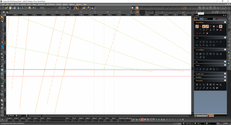
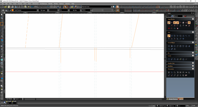
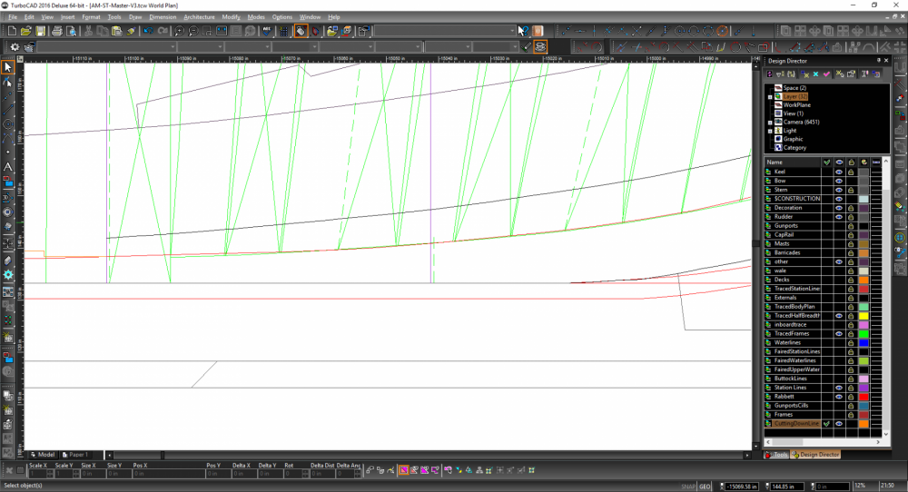
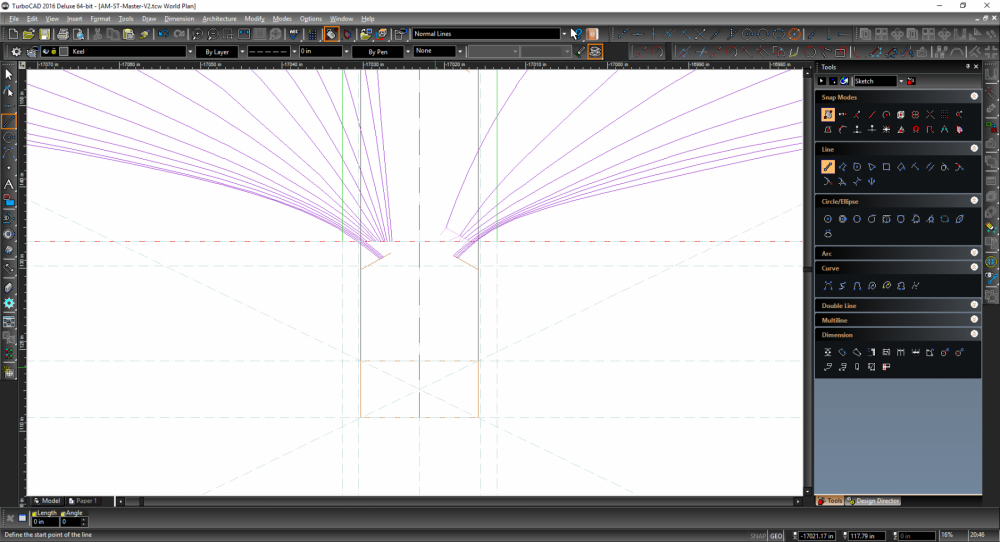
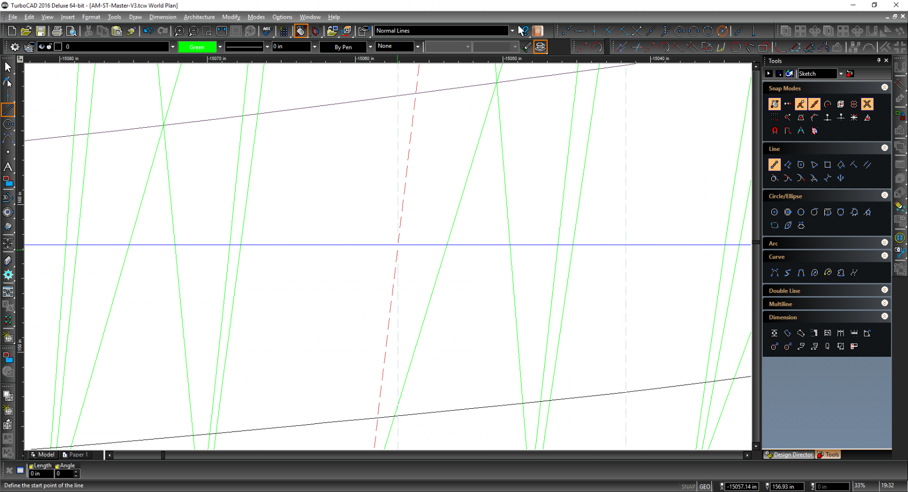
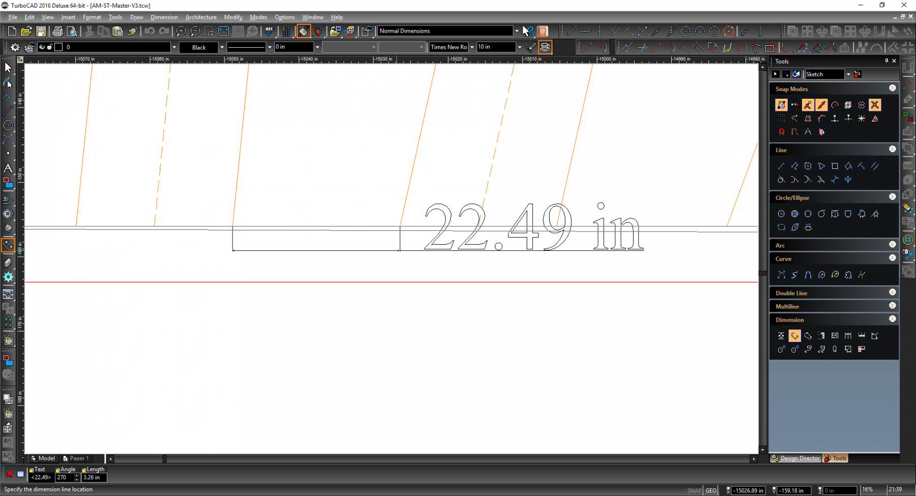
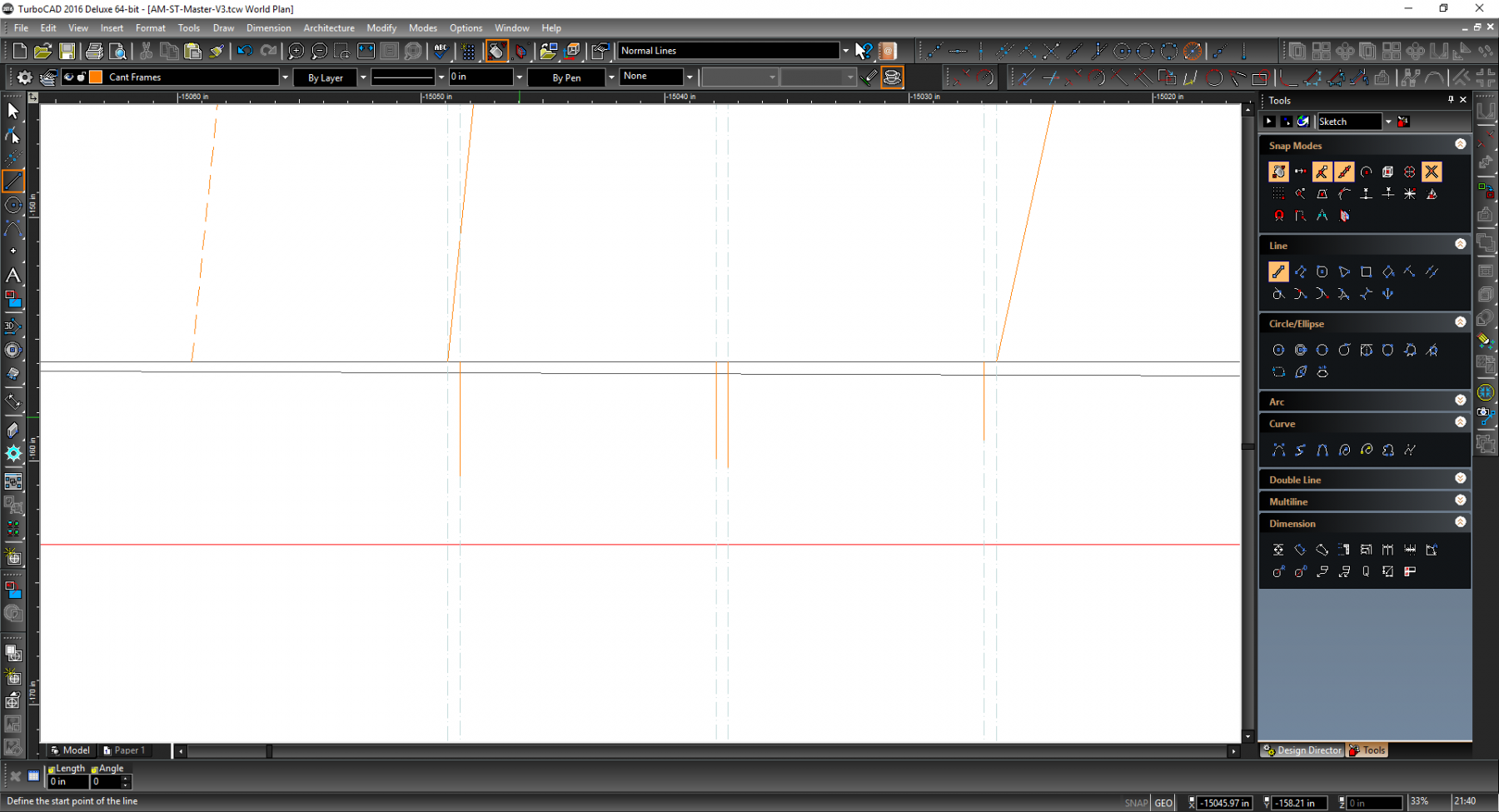
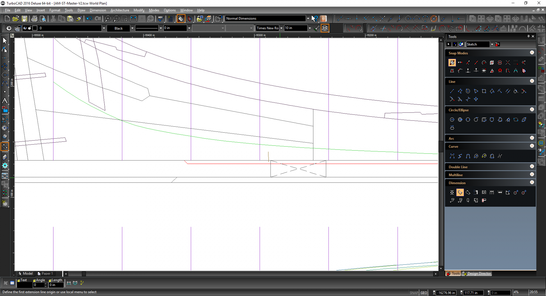
Just returning to this after Christmas. I have been thinking about Hoss's taper recommendations. Taking my frigate she should be 15 inches wide amidships and 12 inches wide at the post/rudder. This is only a taper of 1.5 inches. My current taper starts (at the stern end) around 24 foot from the rudder making it a fairly gentle incline.
Taking the above recommendation then 1.5 inches should take up around 6 foot so 72 inches. This is a much sharper incline but makes some logical sense due to the ships base shape
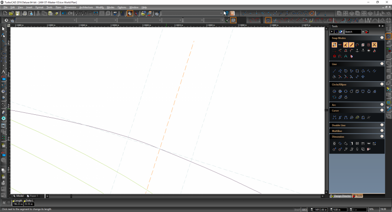
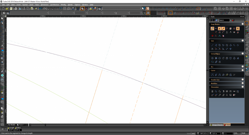
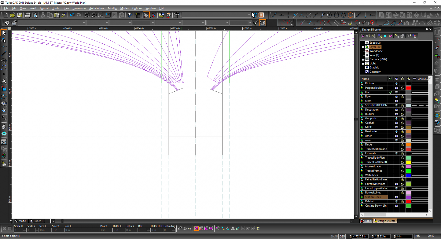
Anyway throwing those locations onto one of the draft plans we get
The left most lime green line being 6ft and the rightmost being the current taper start point.
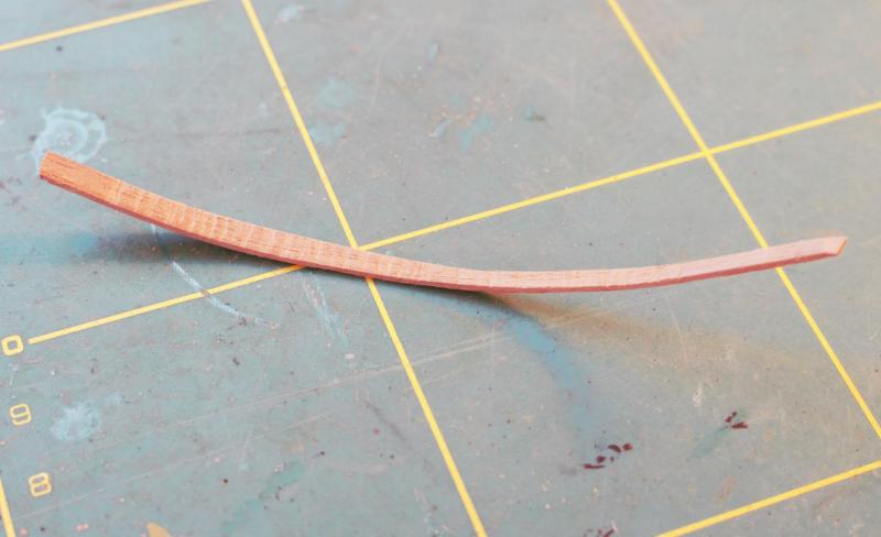
Hmm I am tempted to re-do the keel and false keel plans to see what the taper would approximately look like and perhaps cut it out of some scale wood to see as well.