

Harvey Golden
-
Posts
393 -
Joined
-
Last visited
Content Type
Profiles
Forums
Gallery
Events
Posts posted by Harvey Golden
-
-
21 hours ago, Jim Lad said:
That looks more like a creek than a waterway that can be used by steam powered commercial boats. It's amazing just where large vessels used to operate.
Indeed! I have a friend who kayaks on the Ocklawaha, and he was surprised to hear 80' steamers used to ply it. Historical texts describe passengers being raked by limbs, and some steamers were sunk by snags.
-
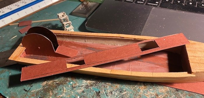
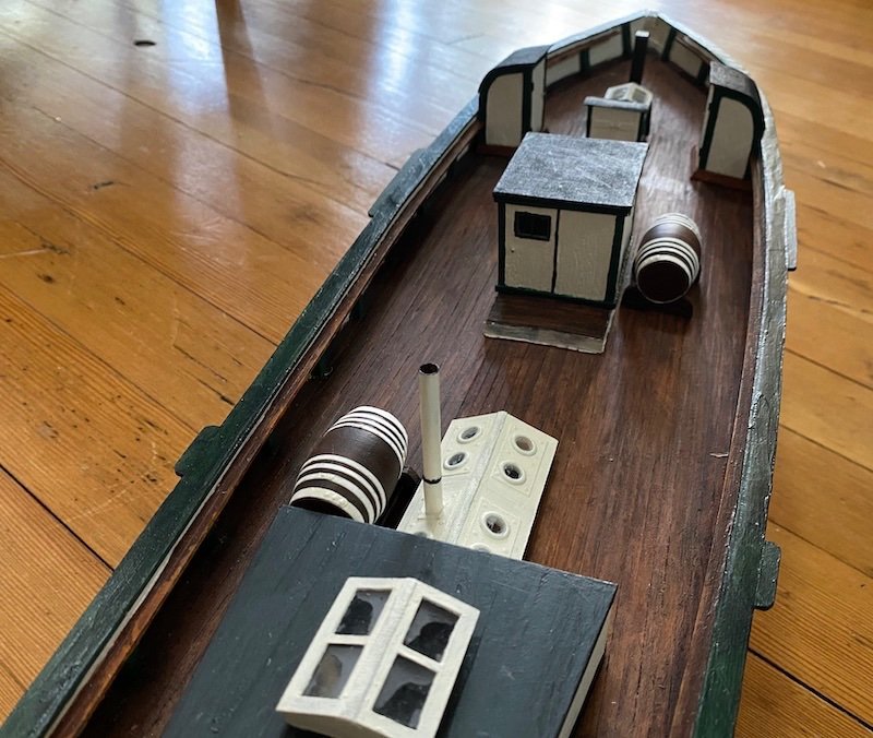
The machinery/engine room is coming together. The plans were a little vague in some aspects, but mostly the issue was I have no understanding at all about steam engines; was a good excuse to brush up a bit on these!
I carved the capstan from a dowel end; not sure how functional the capstan would have been, as it was closed in by stairways on each side. The sides of this room are paperboard with individually laid strips of paper for planking.
Bottom is cross-planked with strips of wood. The recessed wheel casing was a challenge-- both inside and out.
The reason for the inboard wheel was to keep the paddles from snagging in the shallow narrow rivers these steamers were used on-- particularly the Ocklawaha River. The cover of Edward Mueller's book (1990) shows the "Osceola" on that river: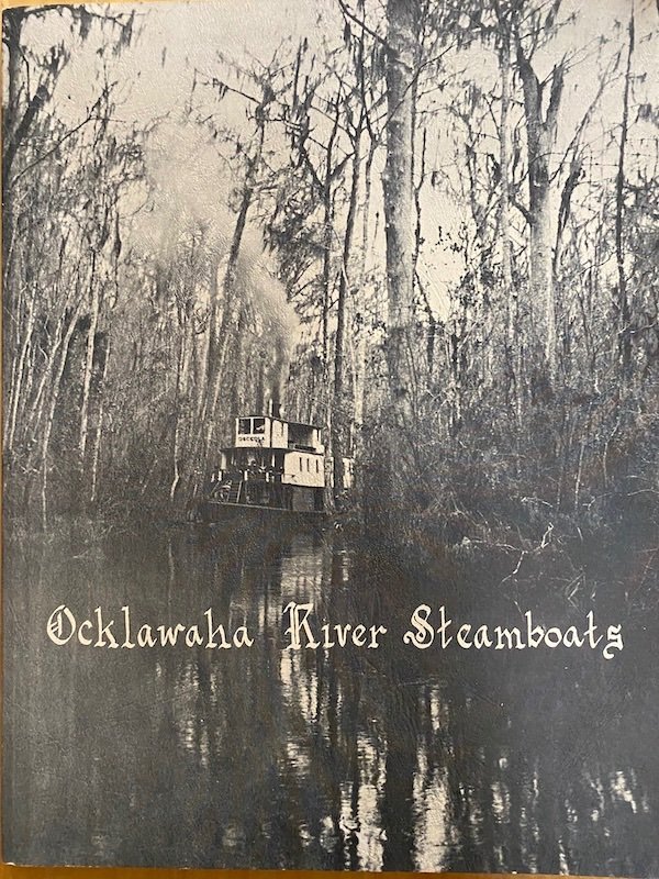
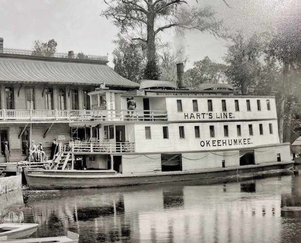
The "Okahumkee" was built like the "Osceola" on the cover above, but a second full deck of cabins were added in the 1890s; my model will be the 'two-story' version. Historic photos show many modifications over the years-- even the name "Okahumkee" was spelled differently on some incarnations (as in the historic photo in the previous post). -
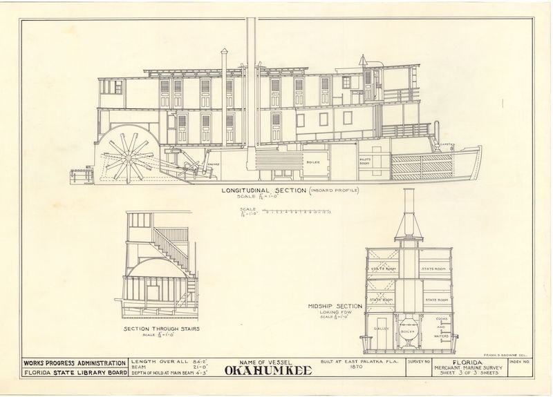
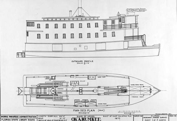
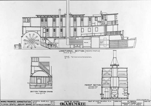
I'm taking a break from my other build-log (Gjøa)-- a little diversion in smaller scale, of a unique craft that caught my eye recently. I first saw this type of vessel in the Historic American Merchant Marine Survey publication of ca. 1984; scale drawings of the "Okahumkee" and its later counterpart the "Hiawatha" are in the Survey. I was interested in building one the moment I saw them. The State Library and Archives of Florida has the HAMMS drawings (3 Pages, retitled) on their web-page (public domain): https://www.floridamemory.com/items/show/337722 Here is the inboard section, which also will show the Inboard wheel:
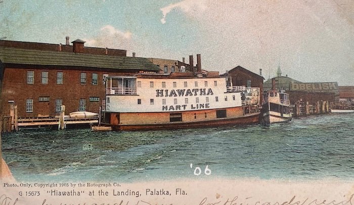
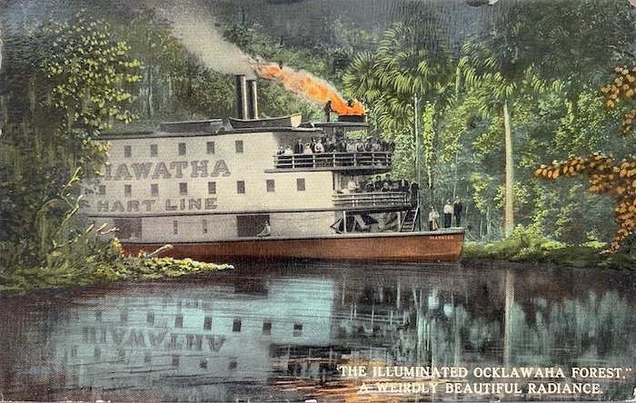
Yes, a little odd looking; Historical descriptions tend to agree.Here's a postcard showing sister-ship (of sorts) "Hiawatha":
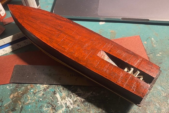
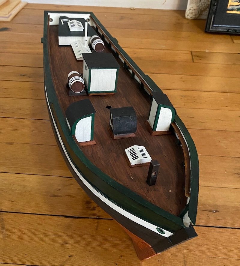
In beginning, I used paper board to make the hull. While 82' long, this steamer is essentially a huge skiff, with only slight dead rise aft of the wheel slot. This paper hull will get a veneer planking.
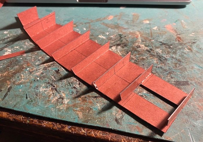
Getting ready to cross-plank the bottom:
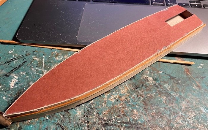
Below: The hull planked bottom, sides and top. The wheel casing is positioned, with the wheel behind it. An inboard sternwheeler is perfect for any builder dreading making the wheel . . . . but I made it anyways, albeit poorly.
Will leave with another historic image (Public Domain, courtesy of State of Florida Library and Archives):
- JacquesCousteau, mtaylor, yvesvidal and 6 others
-
 9
9
-
-
It is just three languages, but Capt. Paasch's "From Keel to Truck" (1885) might be a helpful resource (Digitized by Mystic Seaport Museum): https://research.mysticseaport.org/item/l010988/l010988-c012/
-
If I could squeak one in before closing....
The Hart Line "Okahumkee"-- an inboard sternwheeler that plied the Ocklawaha River from the 1870s into the 1920s. This steamer, and its later-built sister-ship "Hiawatha" are both documented in the Historic American Merchant Marine Survey, and many fine historical photos of each exist. This links to many photos of the Okahumkee, and on one of the three pages there are pages from the HAMMS Survey: https://www.floridamemory.com/find?keywords=Okahumkee (The "Hiawatha" [and other steamers] is also on this web-page).
Here are two Plates from the Florida Memory (State Archives and Library of Florida) page, (Public Domain):
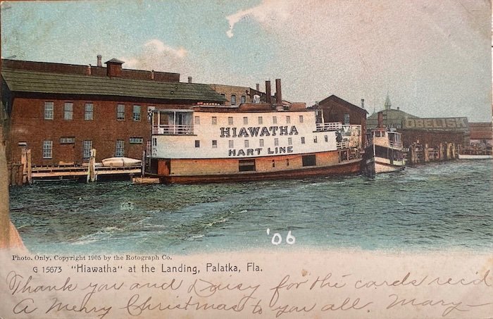
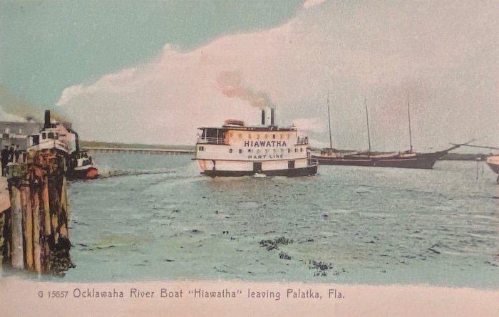
...And a couple postcards of the similar "Hiawatha" from my collection:
Lastly: Here's a model from the 1890s of another Hart Line Steamer in the US Postal Museum:
https://postalmuseum.si.edu/object/npm_0.052985.271
(Full disclosure: I am currently building a model of the "Okahumkee").
All the best,
Harvey
-
Not sure if either of these would be of any help, but I've found them helpful in the past:
NavSource for BB-61: http://www.navsource.org/archives/01/61a.htm
Ship Camouflage: https://www.shipcamouflage.com/usn_bb.htm
-
I think the U.S. Revenue Cutter Bear would be a superb candidate with broad appeal: Sail and steam, 19th and 20th C., WW I and WW II service, Arctic and Antarctic duties, Pacific, Atlantic, and Bering Sea voyages, built in Scotland, etc. etc.
- mtaylor, Canute, Keith Black and 1 other
-
4
-
-
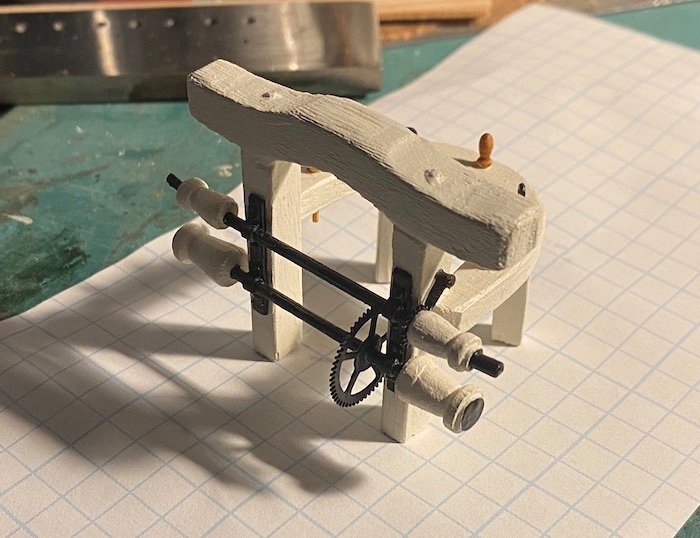
Here's the pump machinery underway, with the pump logs stepped with iron pivot bracket mounted (and corrected gearing on the winch). Thanks again for the photos Steve and Eberhart-- these have been a tremendous help. (Looks like the photos that came with the kit were made during the WPA-HAMMS survey of '36-'37...)
-H
-
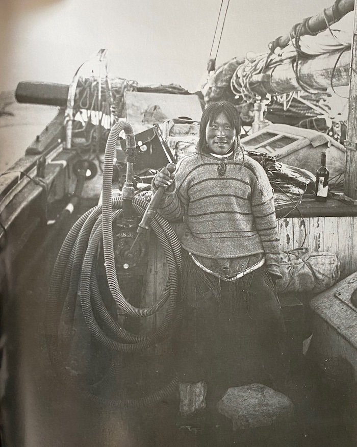
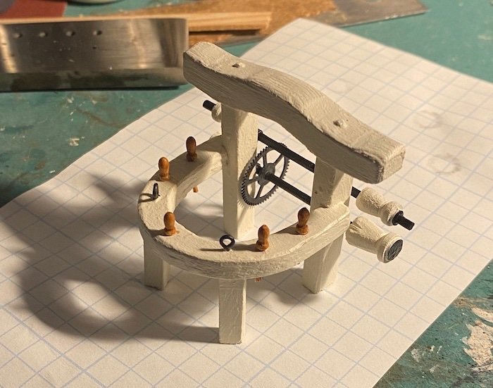
Dear Steve and Wefalck-- thank you both so much for the images and analysis of the Gjøa's machinery. These images are exactly what I was hoping for-- they answer a million questions. Looks like I missed the two smaller gears on the midship winch-- shouldn't be too hard to remedy. Attached is the pump as shown in the historic image above. Also shown: the exhaust pipe for the Dan motor (gray).
-
Can anyone identify this bit of machinery on the Gjøa? The image is from Roald Amundsen's Diaries, as issued by the Fram Museum, Oslo in 2017 (page 485). It was taken at King William Island (the middle of his NW passage transit)-- note the hose running through the stern hawse pipe; perhaps for loading water? Thank you!
- Keith Black, mtaylor and GrandpaPhil
-
3
-
3 hours ago, wefalck said:
I just had a quick look at my pictures of GJØA in the museum, but today this winch is not present on her. However, normally there would be a pinion that engages with the large cog-wheel in order to effect a reduction and mechanical advantage. This may engage via a dog-clutch.
I'll keep searching for old images-- I suppose at some point one must decide whether to put in the likely apparatus or leave unknowns omitted. Too bad she's now stripped down so much in terms of deck machinery-- It does make sense as she's now cleared for visitors. It looks like the aft winch has been moved back, and the galley has been re-positioned aft on the hatch to make it more accessible.
- Keith Black and mtaylor
-
2
-
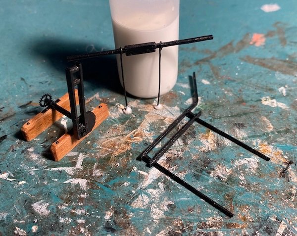
The mast's pinrail is completed, along with some of the attached machinery. The winch heads are hand-carved from dowel ends-- no lathe in my shop. Quite a few other little things to do before stepping the mast, but it's just around the corner. Next I'll tackle the pumps as best I can from limited information-- seems to be dearth of info as to how exactly they were set up; I don't even know what the big gear on the pinrail does or what it connects to, but photos show its presence.
- Mjohn, mtaylor, JacquesCousteau and 4 others
-
7
-
Looks correctly (and quite perfectly!) built to my eyes. The WoodenBoat book series title "10 Wooden Boats you can Build" features this design (1995). The chine logs likely allowed for thinner planking and lighter framing; adapted to plywood (as in the book) would allow for a very light and easy to build boat (stitch and glue construction would preclude needing the chines, but would require more framing and/or thicker planking).
-
Thank you-- some very hard-to-find material there! The link to South East Asian boats is to his study of 'extra-European' boats-- covering the rest of the world. It doesn't seem to have the engravings (issued separately), but here they are for any interested:
https://archive.org/details/essaisurlaconstr02pris/page/n11/mode/2up This is probably one of the finest world-survey of watercraft; I don't think anything since has come close to it, even despite its areas of weakness.
-
2 hours ago, Srodbro said:
Absolutely beautiful work on the windless! I look forward to your interpretation of the mechanism at the pumps.
Thank you Steve! I don't have the best info on the pumps and their arrangement, so it will indeed be an interpretation. Photos of the Gjøa as she is today show her stripped down in this area (merely the stumps and no machinery), and the drawings I'm working from are a little thin or vague in this area. Several historic images will be of great help, though.
- Keith Black and mtaylor
-
2
-
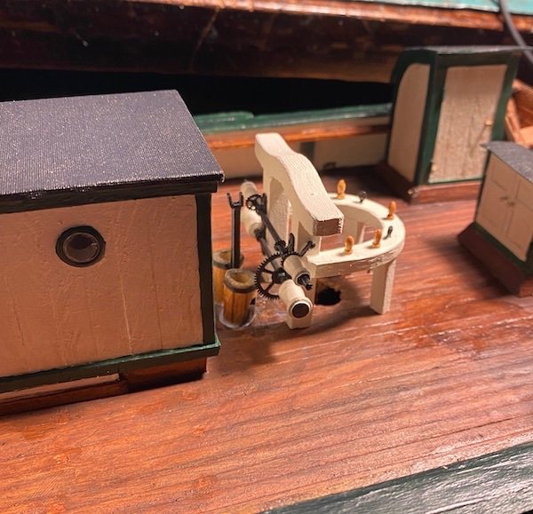
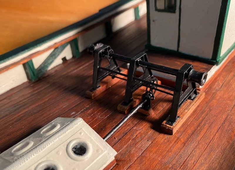
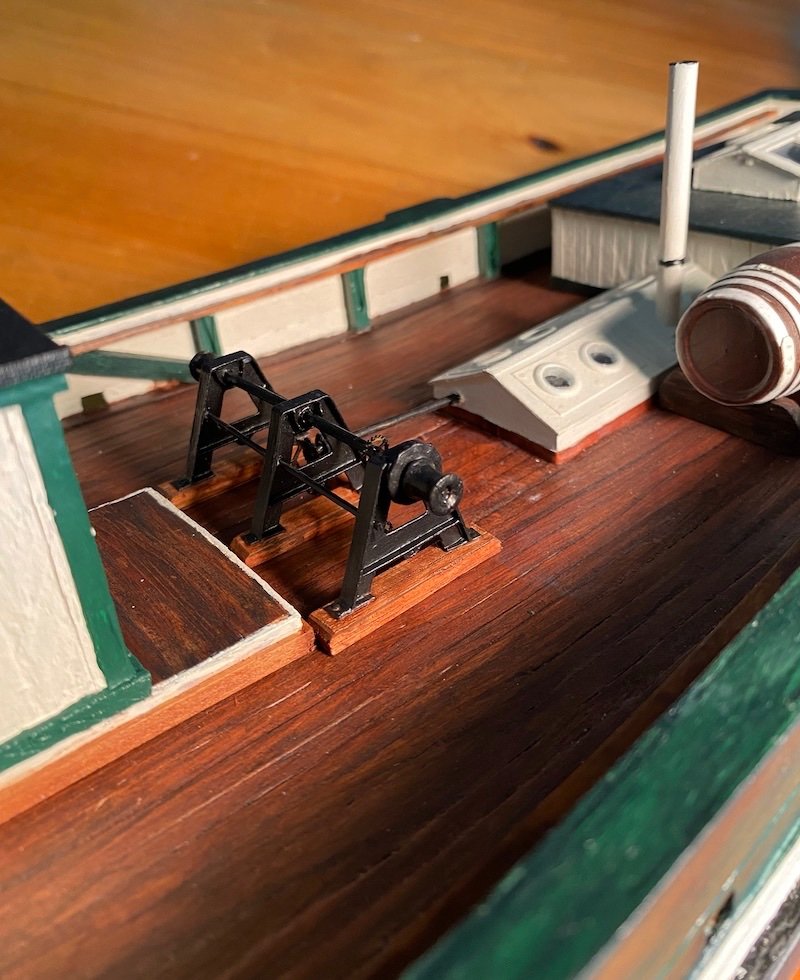
The aft windlass-- an iron structure-- is completed and installed. Made from wood, paper, and watch and clock gears. It was powered by the 3 h.p. Dan engine, hence the drive shaft projecting from the engine room skylight. A messenger chain ran forward from the port side to the pumps and forward windlass. This assembly still needs the chain linking the lower shaft to the upper. Some other details: scuppers as they appeared during the voyage, iron braces for the pinrail, and lastly a view of the whole as she sits today.
- Keith Black, ccoyle, Mjohn and 8 others
-
11
-
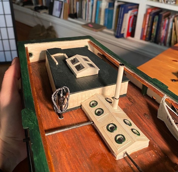
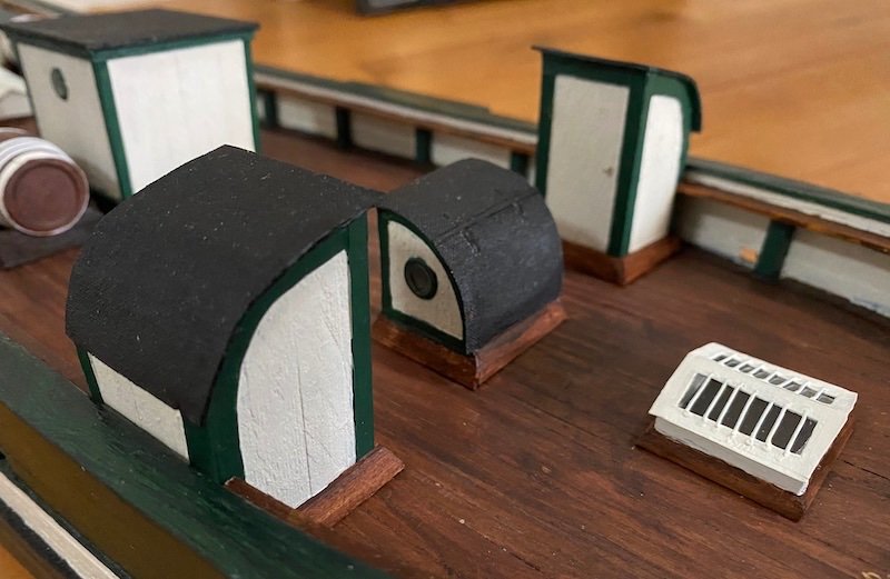
Ending the year with more deck houses installed, including the two 'outhouses' (dry-fitted, so a tad crooked yet). The galley and a bow skylight are in place, and also a few details such as the stack from the engine skylights, two water casks (positioned as-per historic photographs). The barrels are just 'craft-store' kitsch with the carved hoops sanded off and replaced with steel (paper, actually) hoops. The companionway got a book-cloth cover (painted black) to match the galley's roof. I've also started cutting the scuppers in the bulwarks . . . hard to tell how many there were from old photos, and the photos taken of the ship at San Francisco's Golden Gate Park show many changes over the years. They were definitely of a different form than the Gjøa has now (one is visible in the upper photo, to the right). Anyhow, here she is to greet the new year:
-
I use a lot of card & paper on my scratch models-- often just stock pulled from the recycling bin, so I don't even know the types, etc. Naturally, I often have the curving issues you show. I often will glue on strips of wood to straighten them out-- sort of like deck beams, glued to the upper face of the bulkheads. This straightens (and strengthens) them and also provides a thicker base for gluing a deck down. That's just my solution; hopefully a true connoisseur of things paper can chime in. Best, H-
- mtaylor, GrandpaPhil and thibaultron
-
3
-
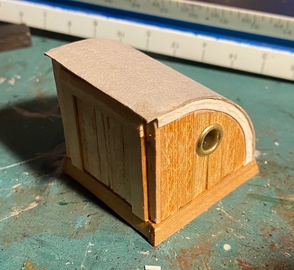
The forward companionway: Here's a bit of the process I'm using in making the deck structures...
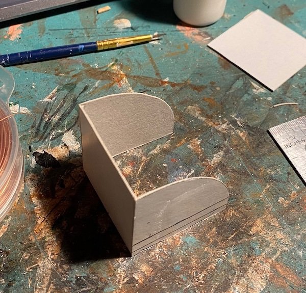
I use card stock to form the shape of the structure-- very easy to work with. Dimensions are slightly under, as this will all be sheathed in wood strips.
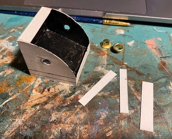
Almost done with the card foundation-- just some reenforcing strips to add. The interior is blackened and the holes for the deadlights are punched.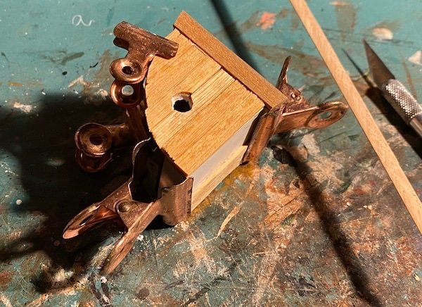
Sheathing in cedar strips. The sills are also of cedar, beveled as shown.
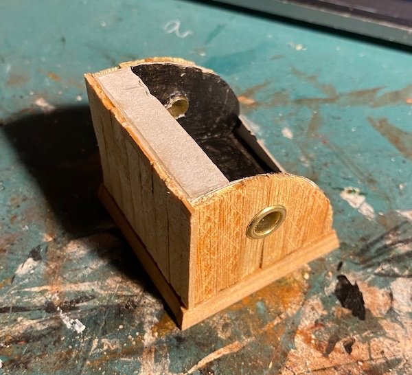
Deadlights in and sheathing finished.
Roof of card glued on and some initial paper trim placed. Hatch is framed. . . and later removed as I didn't like it, and there wouldn't be a header, as the roof was hinged and doors ran to the very top...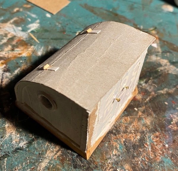
All trim in place; hinges added to roof (and joint scored); hatches in place with brass knobs.
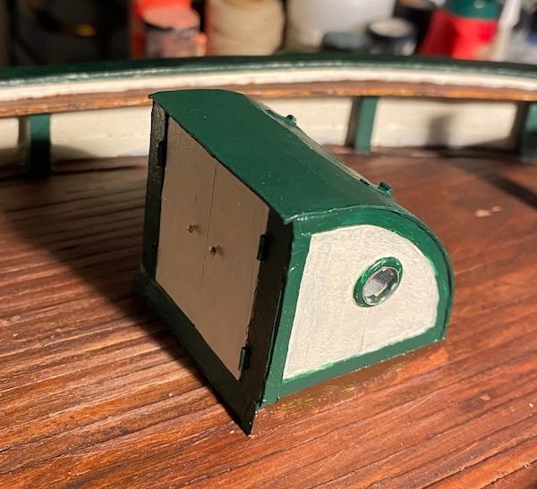
Painted and in place. The white glue in the deadlight should dry and disappear as it dries.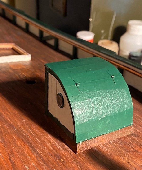
Yes the roof is rumpled a bit. I don't know what the original material was, but I suspect either sheet metal or perhaps more likely cross-planked and then canvased. I might scratch those hinges off and cover it with book cloth. . . not sure yet. FWIW, I like the rumpled look.H-
-
Dear Steve,
I saw your project just the other day-- looking good! We seem to be roughly at the same stage. To be honest, I didn't even notice the lines attached to the tiller in the lines published with Amundsen's account; the plans I'm building from are from the 1930s Historic American Merchant Marine survey, and they don't show the lines. I suspect (but don't know) that the lines would be to set the rudder at desired deflect instead of being used to actually control the vessel moment to moment. There is a compelling photograph, though posed, about 20 years after the expedition that may shed light on this: (second image down)
https://amundsen.mia.no/resource/1903-1906-gjoa-ekspedisjonen-gjoa/
Question is: Is the master goofing or showing how it's done?
As she sits now in Oslo, the Gjöa does have the steering lines rigged to the tiller (attached to iron stanchions at the rear corners of the house).
All the best,
Harvey
- Srodbro, Keith Black and mtaylor
-
3
-
3 hours ago, Glen McGuire said:
Regardless of what the artist did with the wind, I believe the native is sitting on the stern. The only difference it makes is that I have the railing curving downward towards the bow and there is a slight difference in the heights of the kupe's (the bow and stern ends that sweep upward). Otherwise, the whole thing is symetrical.
This looking very nice! The steering oar is definitely astern, and wouldn't be switched end-to-end when shunting (a form of tacking), as symmetrical hulled multihulls had dedicated bows and simply tacked. The end shapes look good-- not sure to what extent anyone knows what the original voyaging canoes actually looked like (the Hoku'lea is conjectural). The upper painting in your above post is of a Tahitian type, which is fairly well documented.
- Glen McGuire, Keith Black, Canute and 2 others
-
5
-
14 hours ago, Keith Black said:
I suggest chucking the dowel for the mast into a hand drill. It works well but beware, a drill used for turning will suffer earlier failure than had it been used for just drilling holes. I smoked mine after a couple of years using as a lathe.
You're doing a lovely job.
Thank you Keith-- I thought about doing this, but decided the bench sander would be easier to handle and set up. I do use my drill my dowel making though, and know what you mean about 'smoking a drill'(!)
Best, H-
- mtaylor and Keith Black
-
2

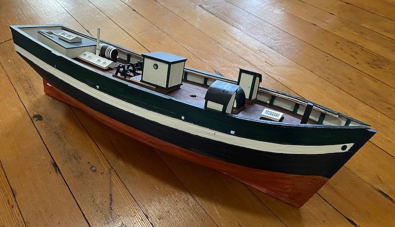
Okahumkee by Harvey Golden - 1/96 scale - 1870s Inboard Stern Wheeler - post 1892 layout
in - Build logs for subjects built 1851 - 1900
Posted
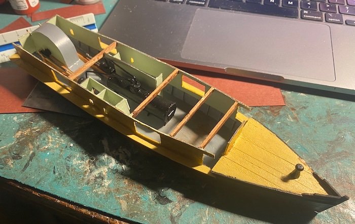
Ready to cover the engine room, galley, and crew quarters. I spent a lot of time splitting firewood, so please don't tell me I need to stack it neatly too. Most of this will not be visible, but I can't help myself with certain details.
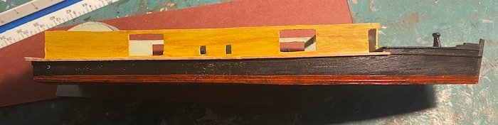
Some details of the bow and stern, with tentative lettering:
The color scheme was a big mystery; vintage hand-colored postcards show the yellow, but a model of the Ocklawaha in a regional museum is dark green instead of yellow. The breakthrough came when I found a Hart Line steamer model (the "Ocklawaha") in the US Postal Museum/Smithsonian's on-line catalog: https://postalmuseum.si.edu/object/npm_0.052985.271 It's a beautiful model, and there are many very good photos of it; it also answered a few questions the plans had left me with.