

Harvey Golden
-
Posts
393 -
Joined
-
Last visited
Content Type
Profiles
Forums
Gallery
Events
Posts posted by Harvey Golden
-
-
Another great source for traditional rigs-- quite specific to smaller craft-- is Nichols' "The Working Guide to Traditional Small-Boat Sails." It has sections on Gaff rigs as well as Spritsails and others. It has been a big help with models as well as full-size craft for me.
Best,
Harvey
- thibaultron and mtaylor
-
 2
2
-
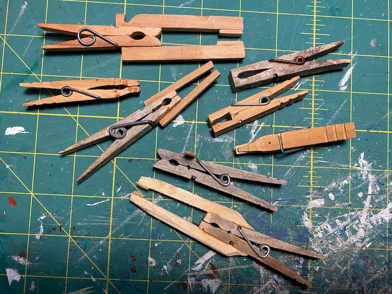
Brilliant binder clip mod! I glued dog-legs onto clothespins to do the exact same thing, but they just don't grip as well. Lovely project too!
-
-
I've tried to find information on Lateen rigs specific to the ones used on San Francisco Bay Feluccas, and a number of photographs of historic examples as well as more recent reconstructions seem to show shrouds only on one side-- the side being opposite the side the yard is on. This leaves the yard quite free of shroud interference, especially in a run. This leaves me with two questions: Am I seeing these correctly? ... And, were the shrouds shifted to the opposite side when the yard was tacked? These vessels would be among the smaller ones to use Lateen rigs, and they were used by Italian Immigrants-- most likely from more southerly Italy. Here is one on-line example I've come across that seems to show this: https://www.nps.gov/media/photo/view.htm%3Fid%3D4D5D2F58-155D-4519-3E15047BCF55EEAB
FWIW, I recently built a model of one from Chapelle's "American Small Sailing Craft" (It's in the Gallery. . . scratch, and not too far down), and it is very much an interpretation, as some details remain vague in my mind. Nevertheless, the physics of the above method make some sense to me (single-side shrouds, opposite the yard), but I really have no idea and no experience. I did run the model's rig by two friends who sailed a recent (1980s-1990s?) S.F. Bay reconstruction, and they said it looked good, despite some years past their handling it.
All the best,
Harvey
- mtaylor and thibaultron
-
2
-
3 hours ago, Jim Lad said:
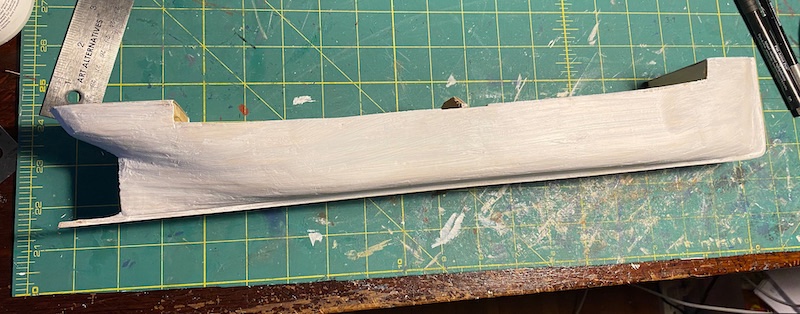
Harvey, might I suggest that you go back over the bow and try a little more sanding there. A smoother hull will result in a far better finished model.
Thanks Jim. It sure could use more sanding. I think part of the problem I've been having is the hardness difference between the pine and the fillers I'm using. Also, the filler seems to shrink a bit with drying, so it often takes several fills.
Best,
Harvey
- Jim Lad, lmagna, Keith Black and 1 other
-
4
-
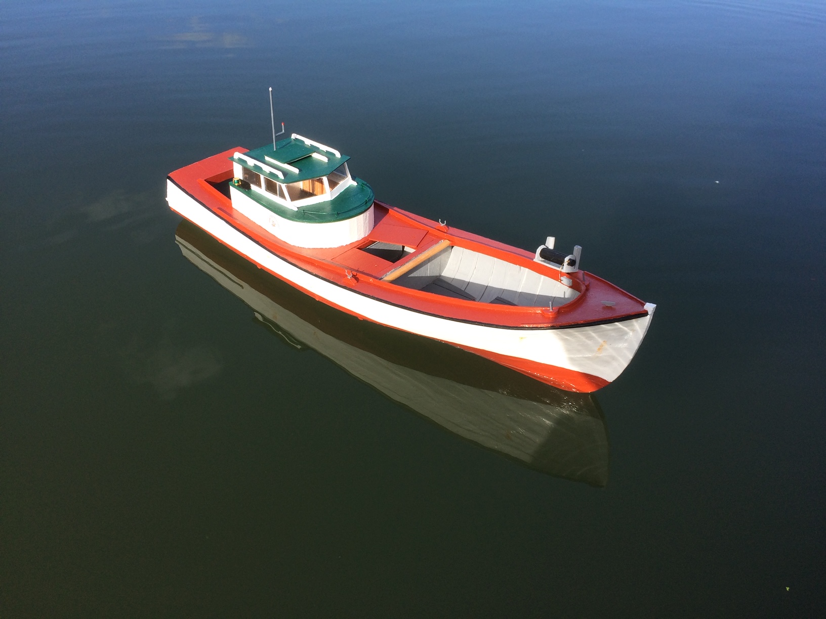
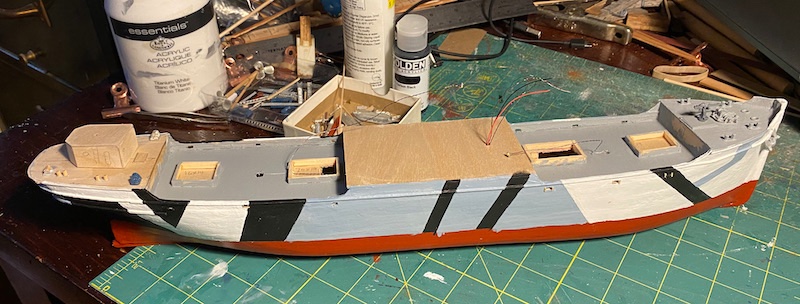
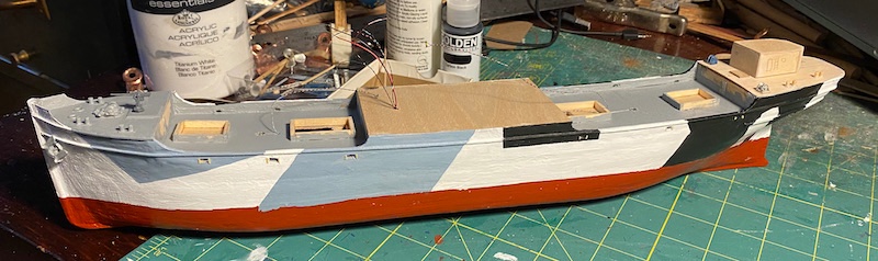
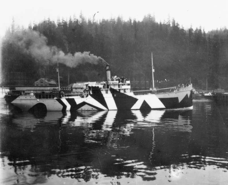
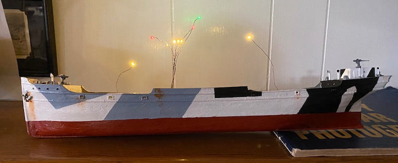
Getting a little color on the hull, and some of the deck furnishings. The scheme is based on the USS Banago, ID3810 (http://www.navsource.org/archives/12/173810.htm). I prefer the scheme of the Calala, depicted in my first post, but I haven't been able to find a depiction of it's opposite side. The fittings are a mix of scratch-built and Bluejacket.
- mtaylor, Keith Black, lmagna and 3 others
-
6
-
-
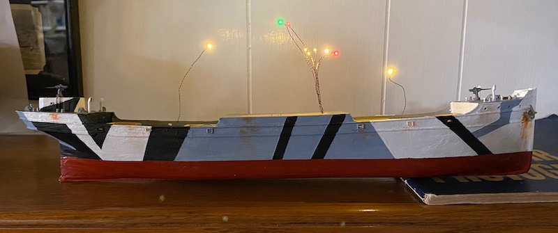
Coming along . . . I'll be putting LEDs in this model, so two white all 'rounds, red and green side lights, cabin lights, and probably a red wheelhouse light. Takes a lot of advance planning to do this, and entails having annoying wires sticking out for most of the process. (LEDs from Evan Design-- a sponsor on the MSW sidebar).
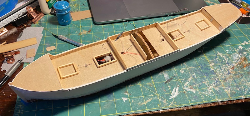
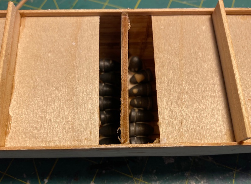
A peek into the hold reveals a substantial number of 70-inch non-explosive artillery shells . . . or is that just ballast for the model? 😉
- lmagna, GrandpaPhil, KeithAug and 4 others
-
7
-
10 hours ago, lmagna said:
Sorry for the misunderstanding Harvey. The picture is not my build. My Lindberg kit is still in the box. I just posted an internet picture of a built Lindberg Q ship model to show what the kit looked like built. It is a pretty small model but looks very similar to yours.
Ah-- no matter. I appreciate the photo, as it sent me down the rabbit hole on Q-ships (and Lindberg models). Thank you!
-
2 hours ago, lmagna said:
Nice start Harvey
Some time ago I bought the Lindberg "Q" ship with the idea of using it much the same way and taking the lines from the plastic model and build a bigger model from it.
Thank you. That's a lovely job there! I usually build small craft or later freighter types, so this is my first vessel with ratlines. Your model's ratlines look very nicely done.
- mtaylor and Keith Black
-
2
-
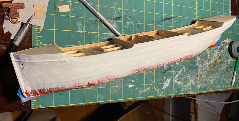
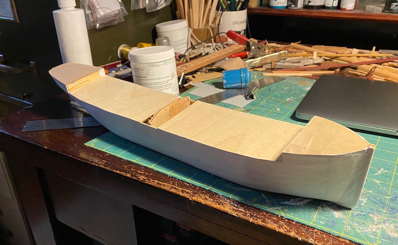
The hull is now cleaned up a bit and primed. Also, the decks are on, along with the keel and stem. Next step is to build up the bulwarks and center island's sides.
- Keith Black, Roger Pellett, lmagna and 5 others
-
8
-
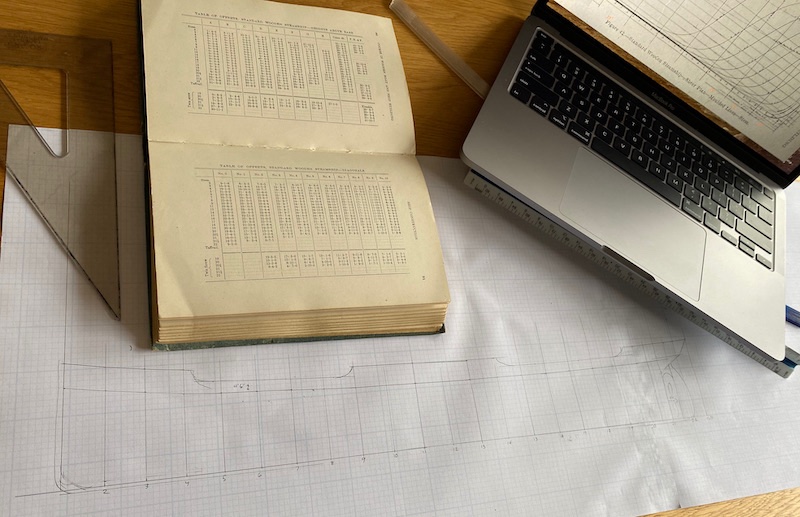
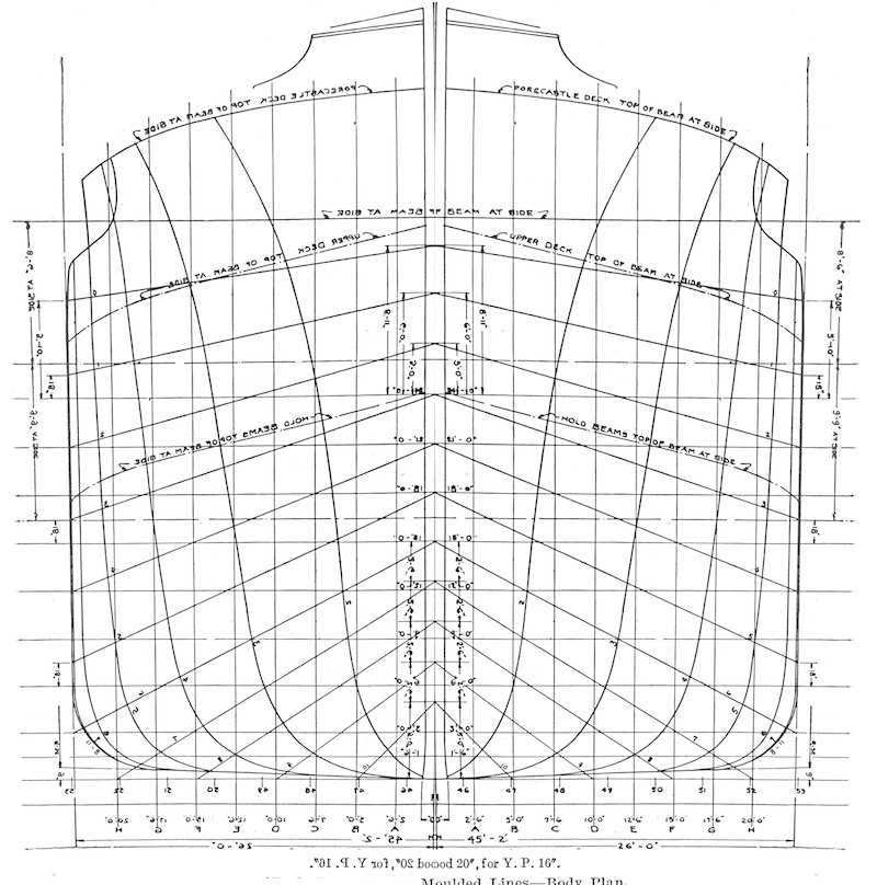
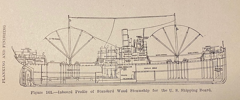
It's always nice to have a drawing the same size as the model one is building. With the rough hull I ended up with, it's especially handy, as I need to get the 'castles' and bulwarks built up correctly. Here is the heights lofting, made from tables of offsets. Van Gaasbeek includes complete elevations, but they are greatly reduced, and some of the numbers are rendered illegible. Still very helpful though, as it provides many details the offsets do not have.
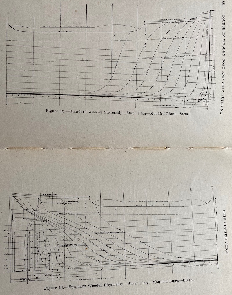
Elevations in Van Gaasbeek: (The dashed lines in the stern view are for the twin-screw version). Note the 13' station distances, and the commission of 4 identical center stations.
- GrandpaPhil, KeithAug, Keith Black and 1 other
-
4
-
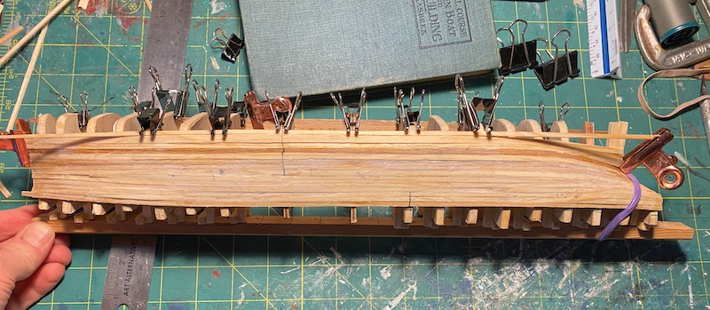
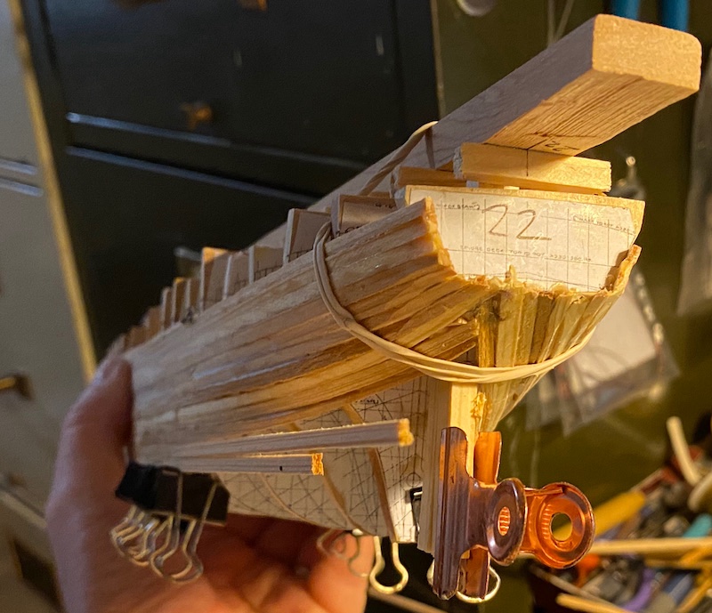
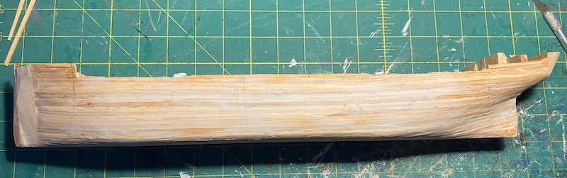
Planking the hull. A rough job, for sure, but after puttying, it'll sand out nicely. Before I turned the bilge with planks, I removed the strong- back. Last photos show the solid block ends in place, and rough-ground to shape. I work a little 'backwards,' in that the stem, deadwood and keel will be added after the planking.
- KeithAug, Keith Black, GrandpaPhil and 2 others
-
5
-
Make sure he has a box of tacks. He's gonna need them. . . 😉
-
Painters' Tape is helpful.
- RichardG, thibaultron and Rob S
-
3
-
-
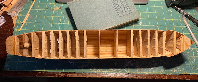
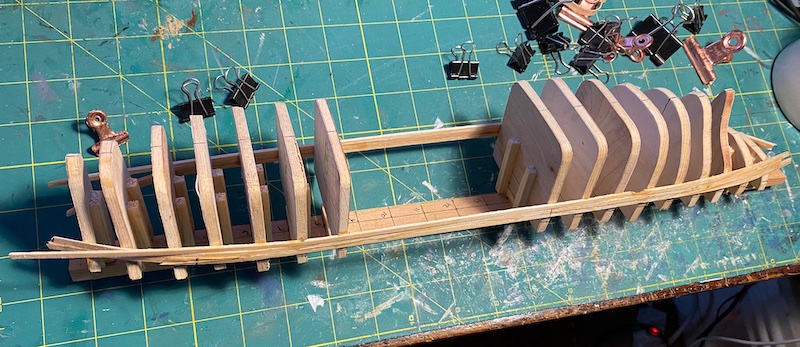
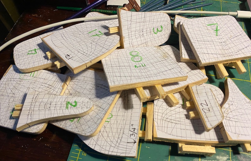
Moulds are all set up, and are fair. I'll use solid pieces for the stem and fantail, so the planking will be from stn. 2 to 22. Station spacing is a little quaint at 13'(!) I'll drop in a few more moulds amidships in due course. Nothing fancy here-- just pine scraps milled to a touch above 1/16" thick by random widths around 1/8" or so.
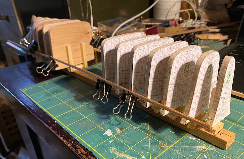
Here's a close-up of the forward moulds-- mirrored via. photo editing, and scaled on MS. Word. No scanner here, so just took the image with my phone camera. From here, I just print 'em off, cut 'em out, and glue 'em to plywood. They are ground to the lines on a bench sander.
- GrandpaPhil, mtaylor, KeithAug and 4 others
-
7
-
-
Hello all! First build log here. This is a type that was built in several yards around my hometown Portland, Oregon (among other places around the U.S.). They were built in wood 'round these parts, and came in single- and twin-screw versions, each being 281'6" long. I'll be building a single-screw version. I've actually been aboard one of these, though I didn't know it at the time. There's one embedded at the lower end of an Island on the Columbia River, and I used to visit it fairly often via kayak. I always wondered what it used to be, and with the ruler tool on Google Earth, it's measurements (LxW) are pretty darned close to a Ferris ship's. . . not that I recommend measuring ships from outer space. Here's some pics of the derelict:
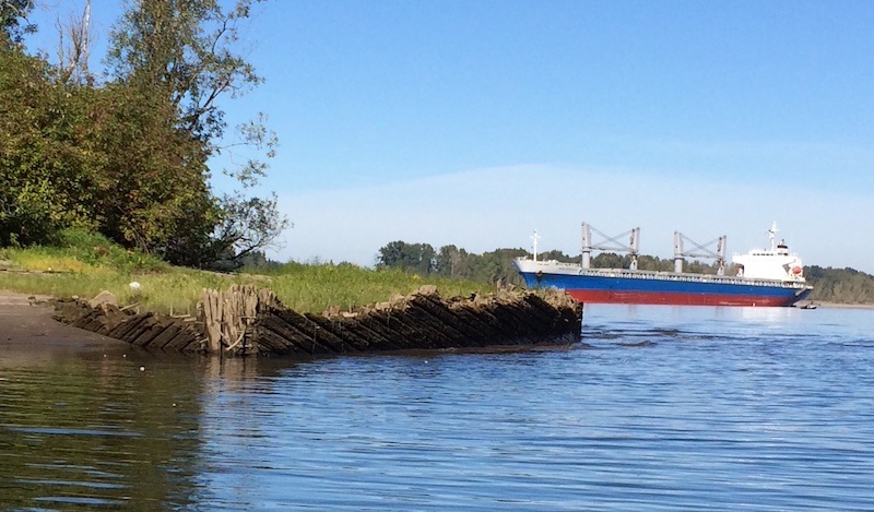
Bow of the ship, at the downriver end of Caterpillar Island, due West of Vancouver, WA.
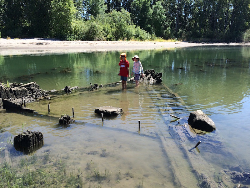
Two survivors still aboard, at the bow.
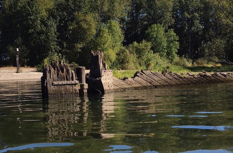
The rudder, cocked to port, and the rudder post, and screw aperture and stuffing box(?)

And here she is, courtesy of Google Earth.
My source for the build will primarily be Richard M. Van Gaasbeek's 1918 "A Practical Course in Wooden Boat and Ship Building." The book has complete lines (though rendered rather tiny) as well as offsets, profiles, and detailed deck plans. Many of the photographs are from Peninsula Shipbuilding Co., just 10 miles from the site of this wreck. Here's some sample pages from the book that show the Ferris type in better condition:
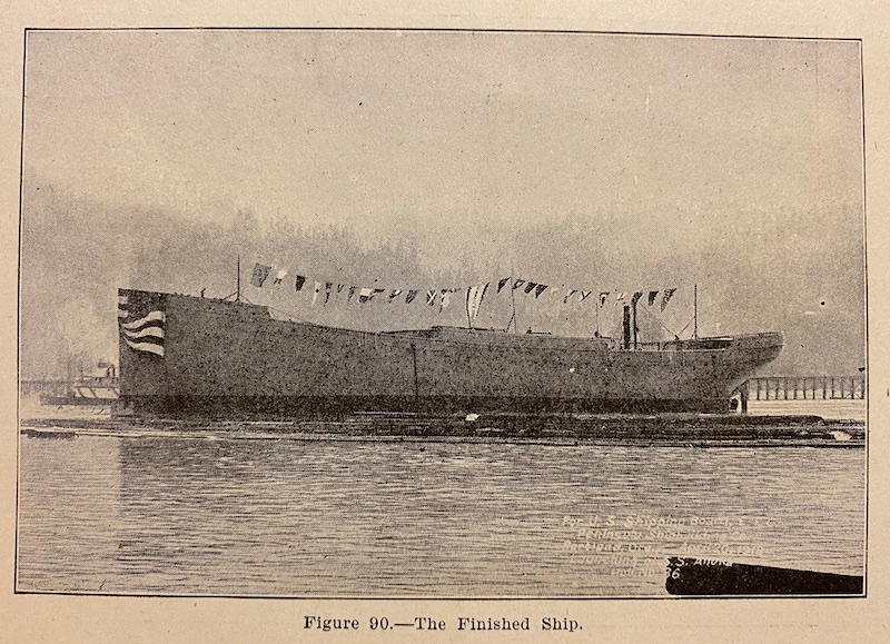
Lastly, here is an exceptional image of a completed one (S.S. Calala) on the Willamette just below Forest Park. Image is Public Domain, courtesy Oregon Historical Society.
The model will be strip-planked on bulkhead at 1/16"=1'. Here's where I am today:
- GrandpaPhil, gieb8688, Tony Hunt and 7 others
-
10
-
Yes to clothes pegs! Though we call them clothes pins up Oregon way. Highly adaptable, too!
- Duanelaker, Phil Babb, grsjax and 5 others
-
8
-
-
Sealing plywood with epoxy doesn't add strength per-se, but does harden the surface of the wood (and a touch below the surface). This increases it's abrasive resistance and dent-proofs it. Do take steps to avoid amine blush-- I'm a victim of this, and it will add the nastiest gunkiest hours of scraping un-set paints or varnishes off your surfaces. Another tip-- for epoxy runs, get them before full-cure with a cabinet scraper, and you'll enjoy time not sanding. Great project, BTW!
Best, Harvey
-
-
I've no knowledge at all about this particular subject, but I have recently been reading in the Hakluyt Society's publication of William ("of Gravesend, a Gunner" [c. 1535-1582]) Bourne's "A Regiment for the Sea" (1963/Kraus Reprint 1990). There is a bibliography of Bourne's other writings, and a couple are titles suggesting some content of ship and/or shore artillery. They are manuscripts from the late 1500s, perhaps not re-published. (The "Regiment" itself concerns navigation entirely, but the re-print has a fine introduction and biography of Bourne).
Best,
Harvey

 ) was located on the Spray?
U.S. Shipping Board Design #1001: "Ferris" Troop Ship ca. 1918-1919 by Harvey Golden
in - Build logs for subjects built 1901 - Present Day
Posted
A little more progress: Bridge deck and boat deck are in place. The screw showed up, so the rudder post is in place with the screw aperture refined. One photo shows how the light from the LEDs is diffused inside the deck houses: The LEDs are dropped down white-painted plastic straws. The last three 'midships lights are the port and starboard running lights and a red wheelhouse light.