DocBlake
-
Posts
1,811 -
Joined
-
Last visited
Content Type
Profiles
Forums
Gallery
Events
Everything posted by DocBlake
-
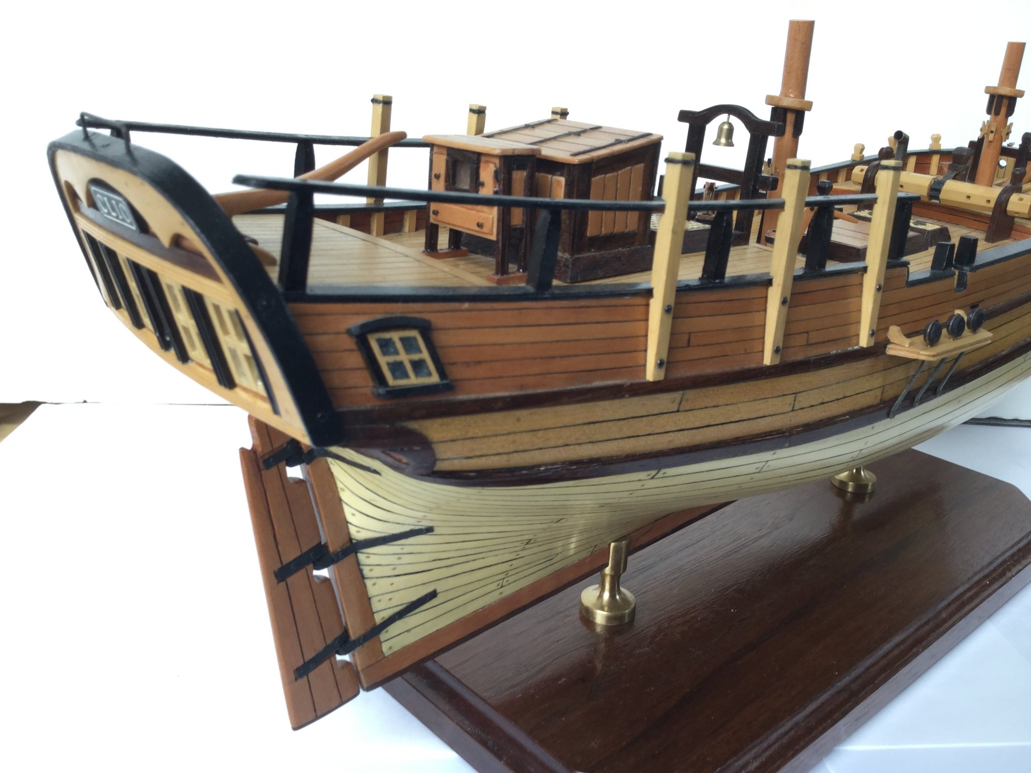
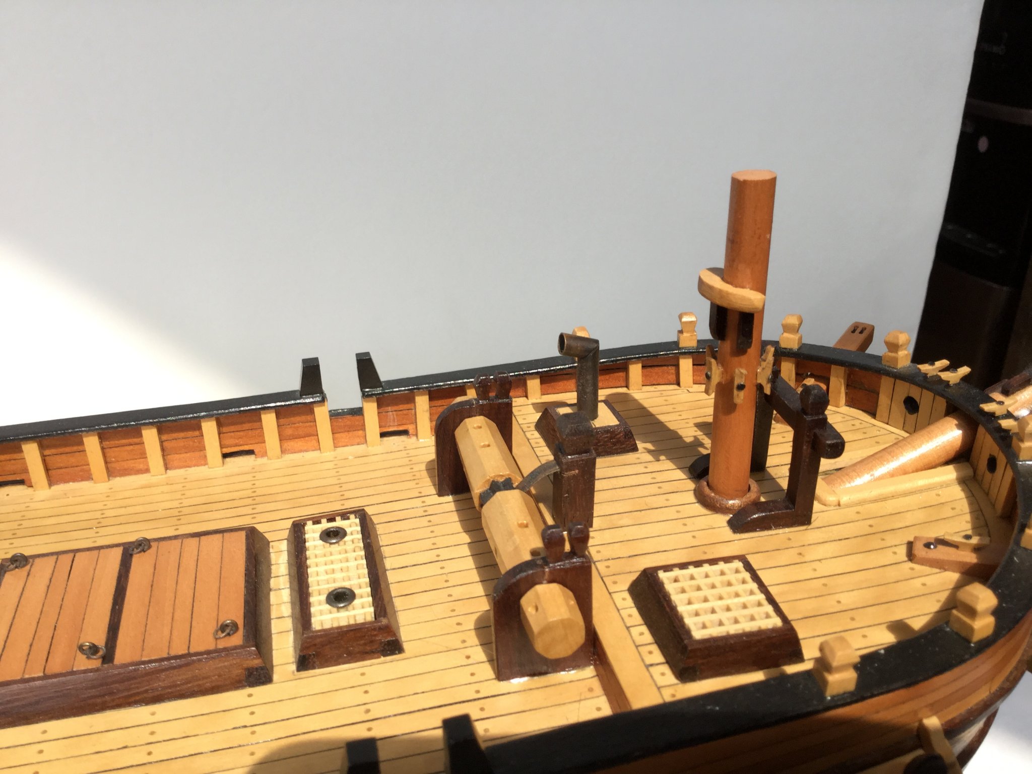
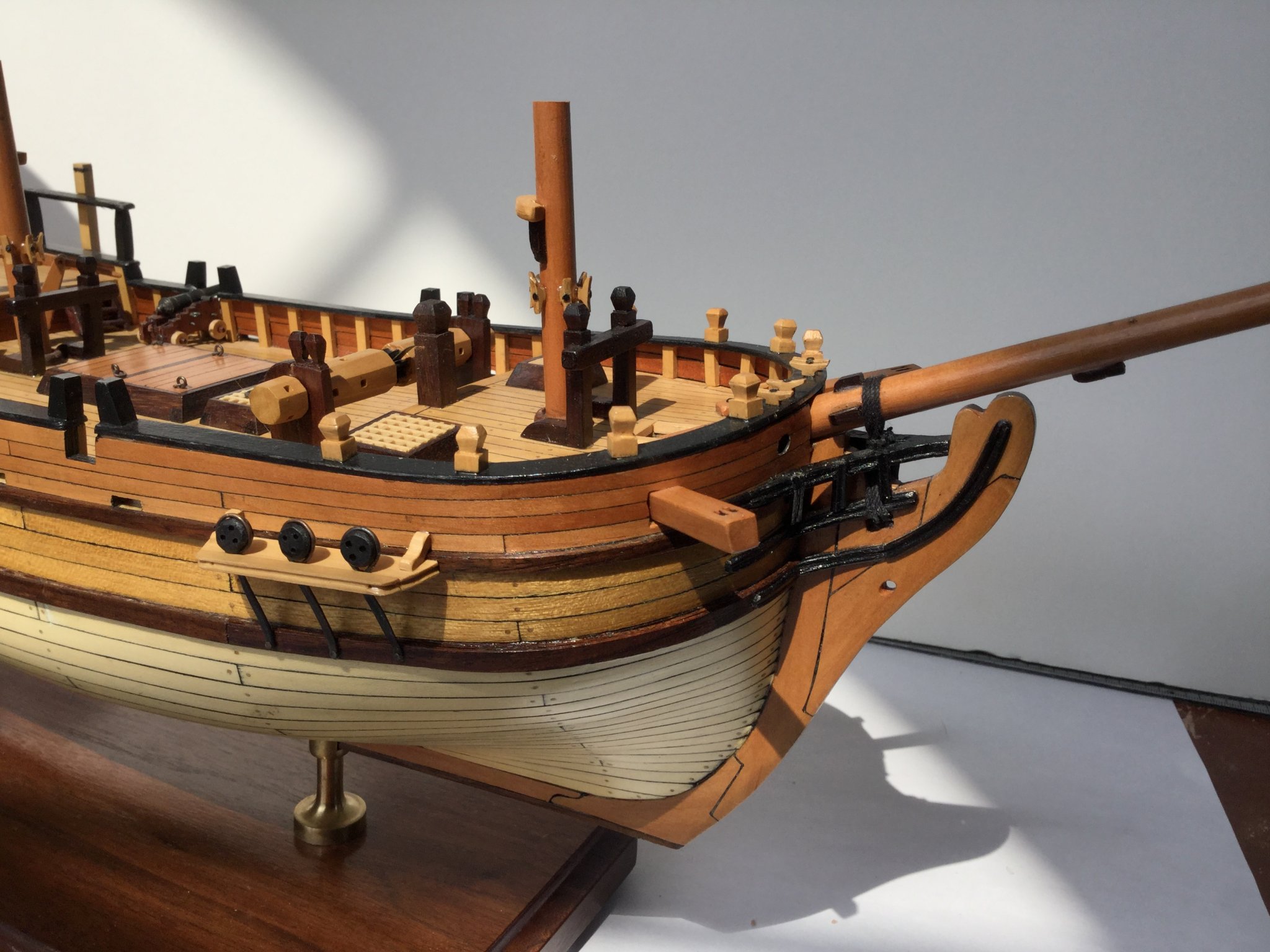
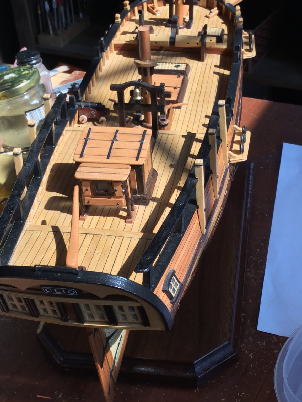
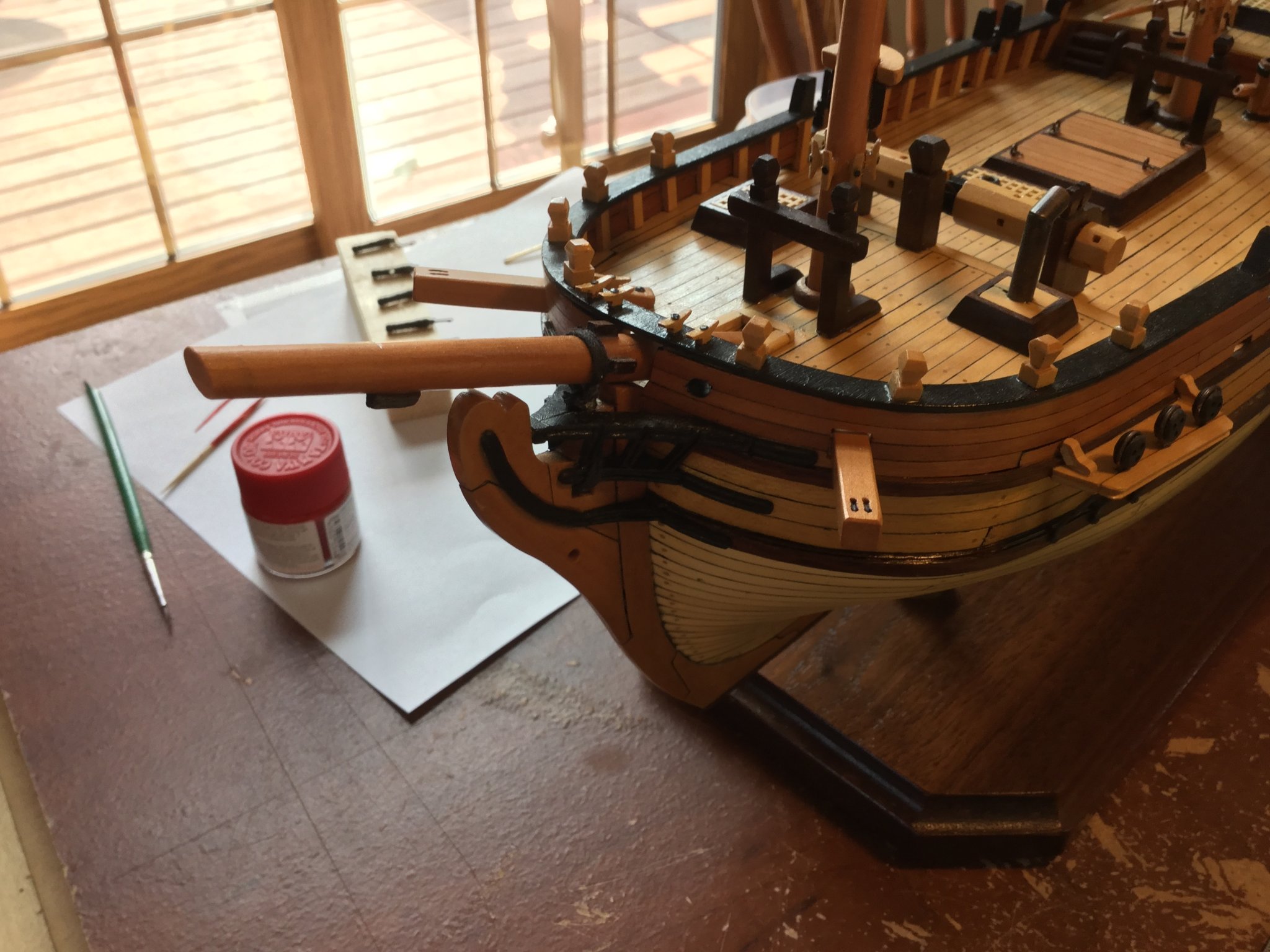
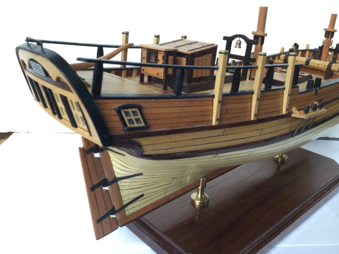
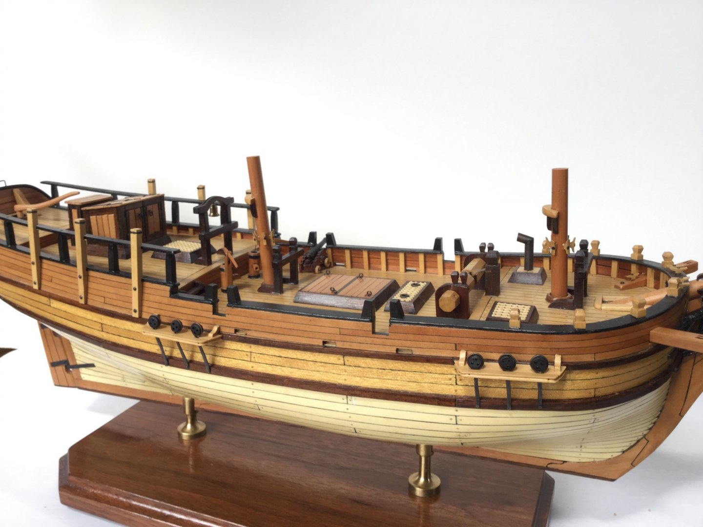
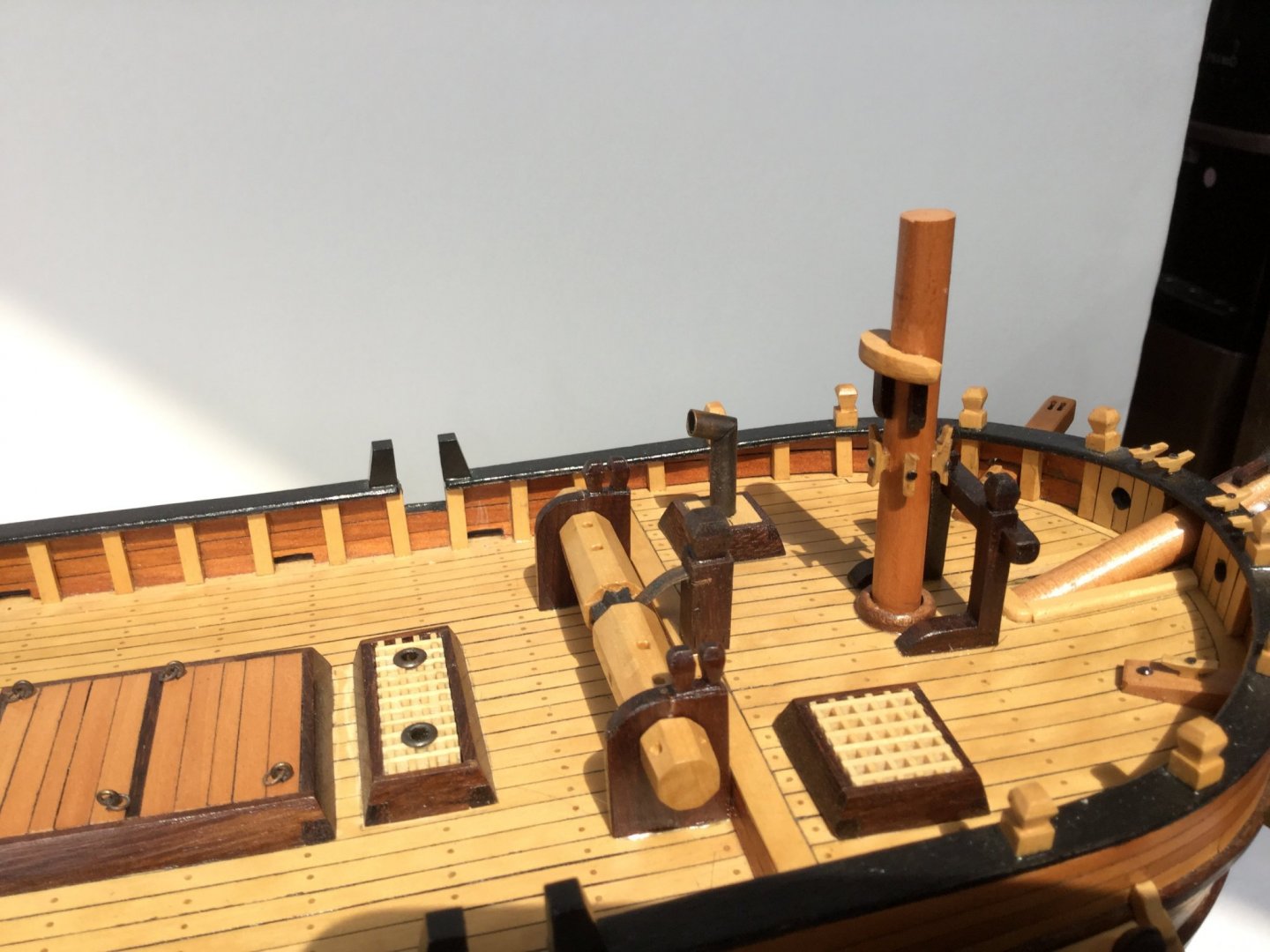
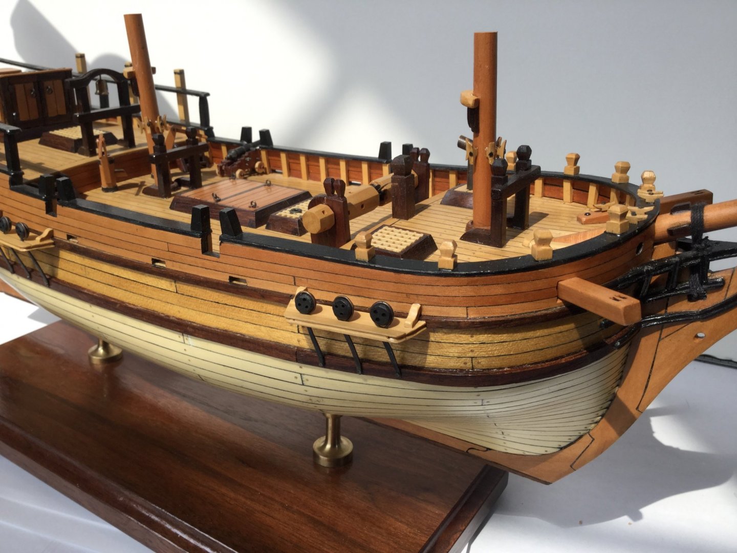
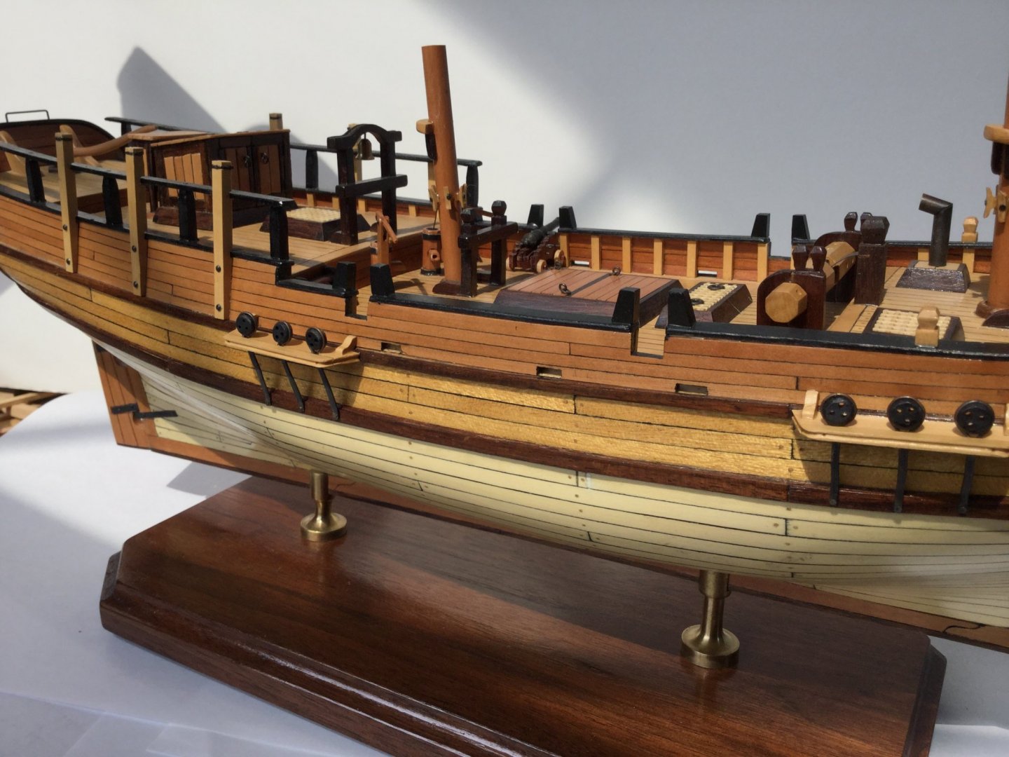
 I finally made the conversion to stub masts and bowsprit. I save the full masts and spars and didn't glue the stub parts in place in case I change my mind. The only jobs left are to finish and mount the swivel guns, rig the cannons and rig a single anchor.


-
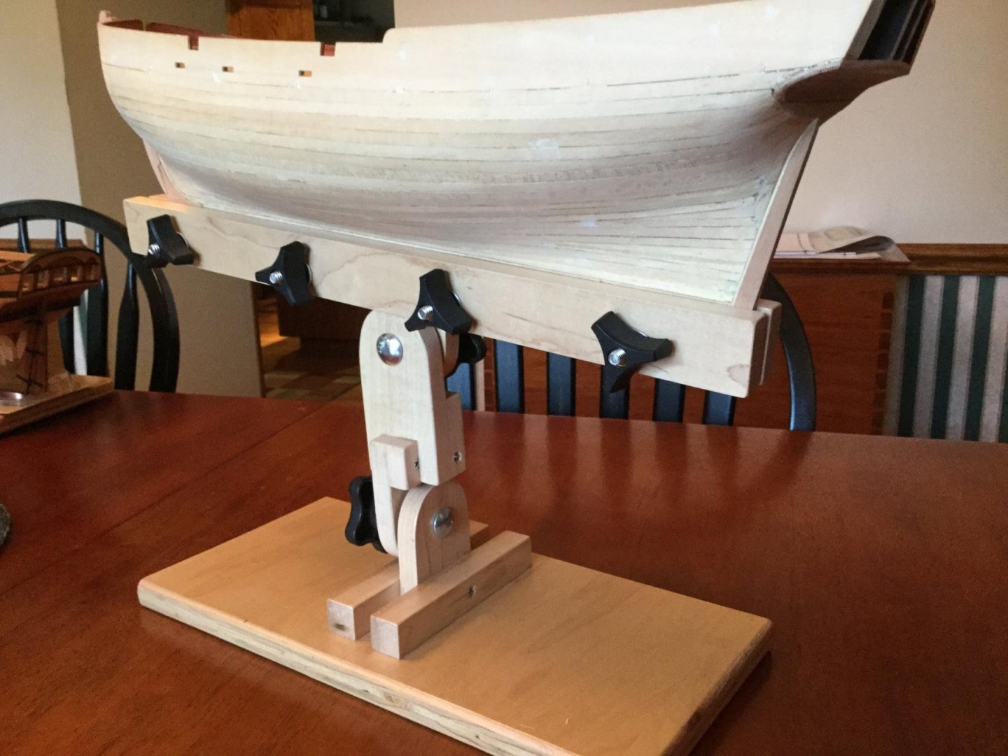
When starting my "Independence" build, I felt I needed a keel clamp. Rather than buy one, I made one from stuff I had around the shop. The clamp is made with all hardwood and a plywood base. If you use simple hardware, the whole clamp will cost less than $10. With fancy star knobs, maybe $20. The clamp is solid and versatile. Plus it is fun to build. The .pdf file includes step by step instructions with photos and detailed, measured drawings. Enjoy! Doc's Keel Clamp.pdf
-
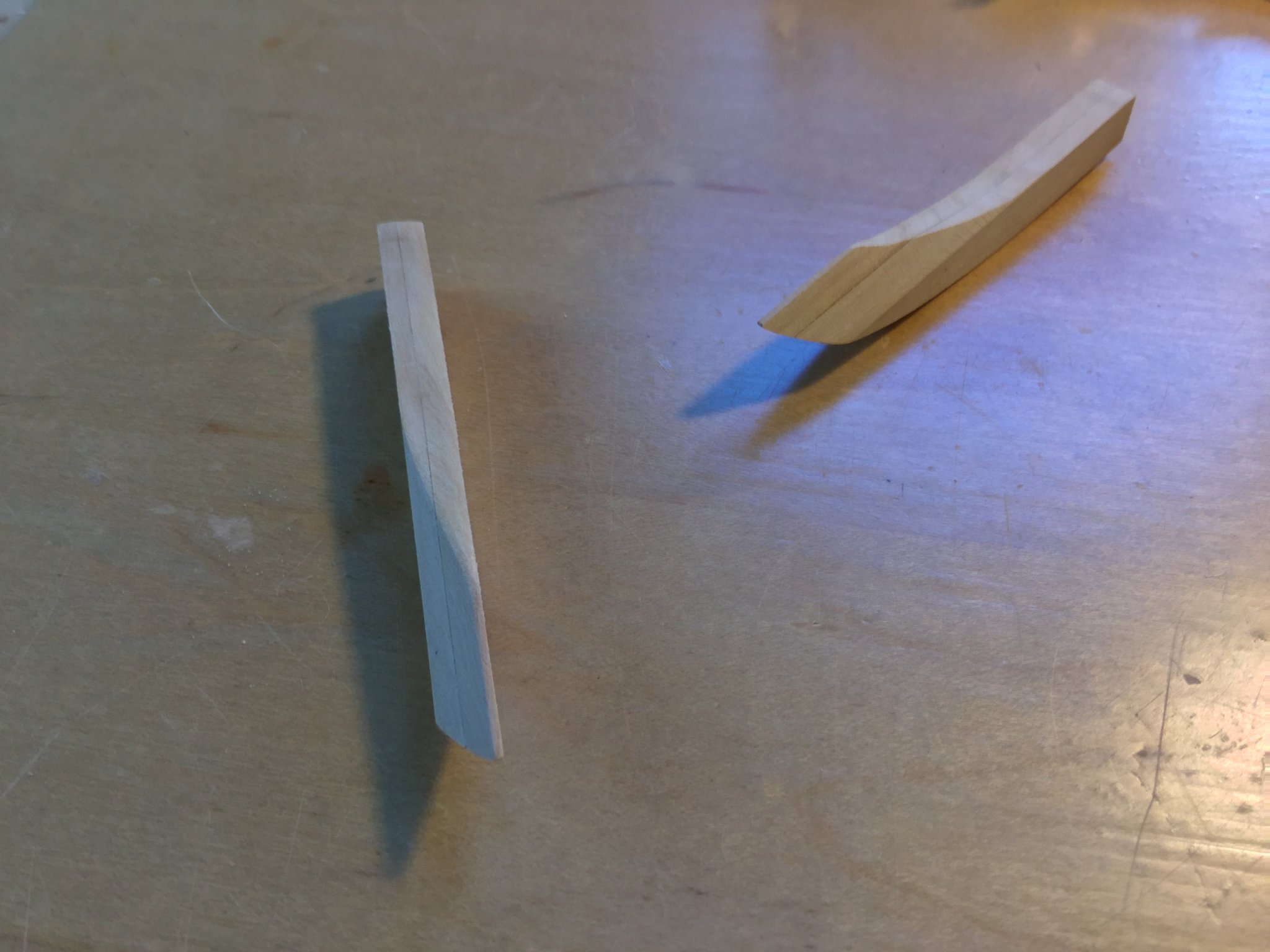
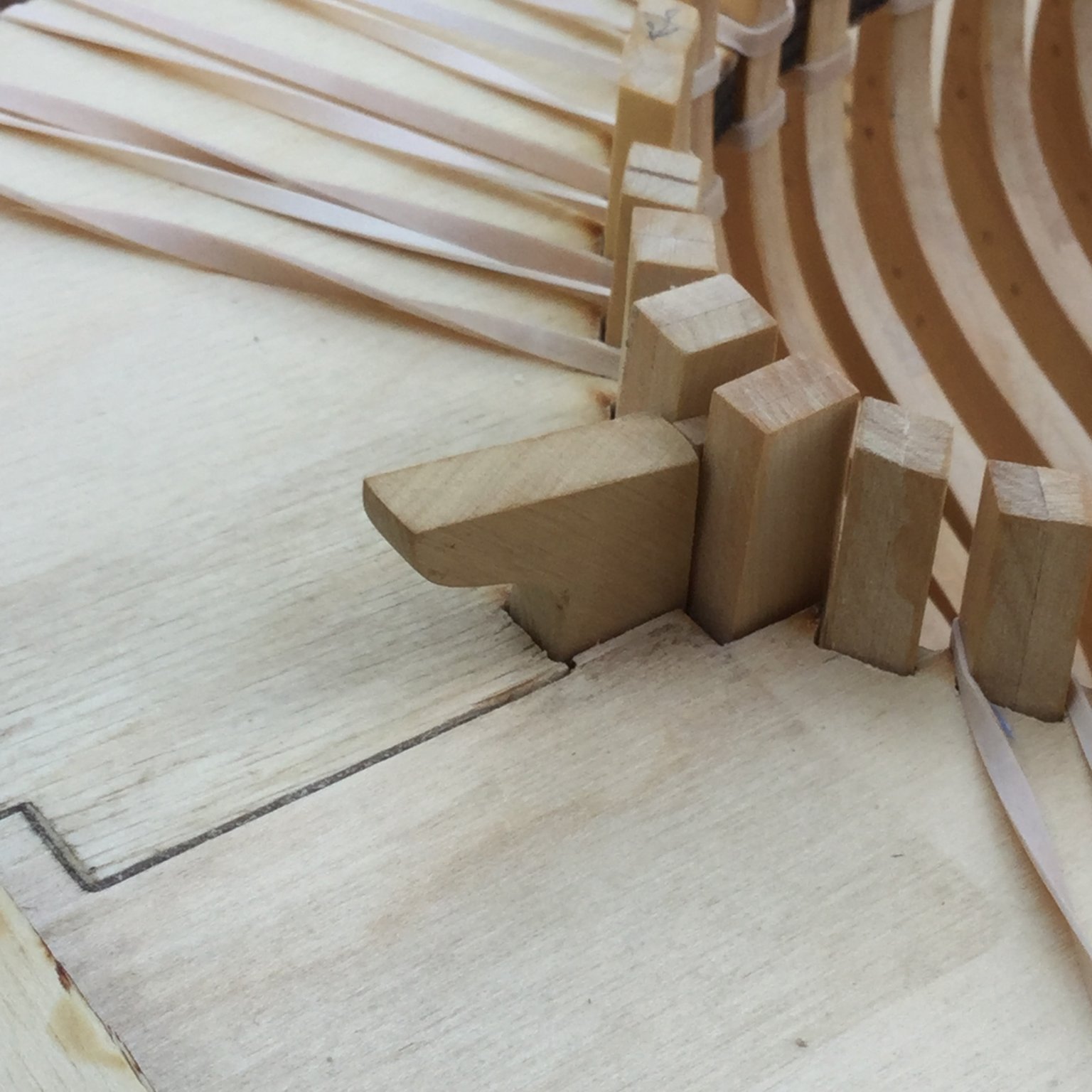
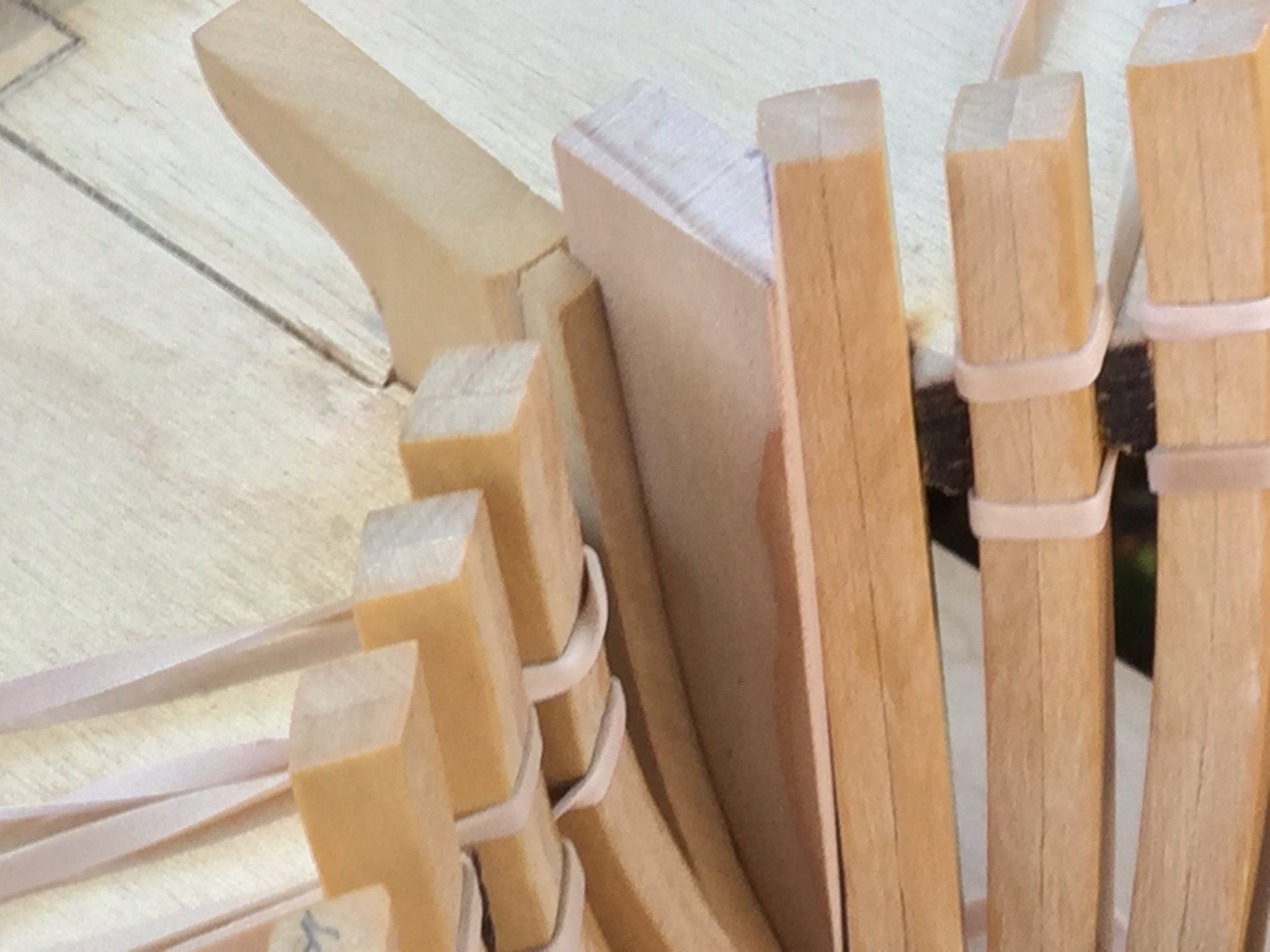
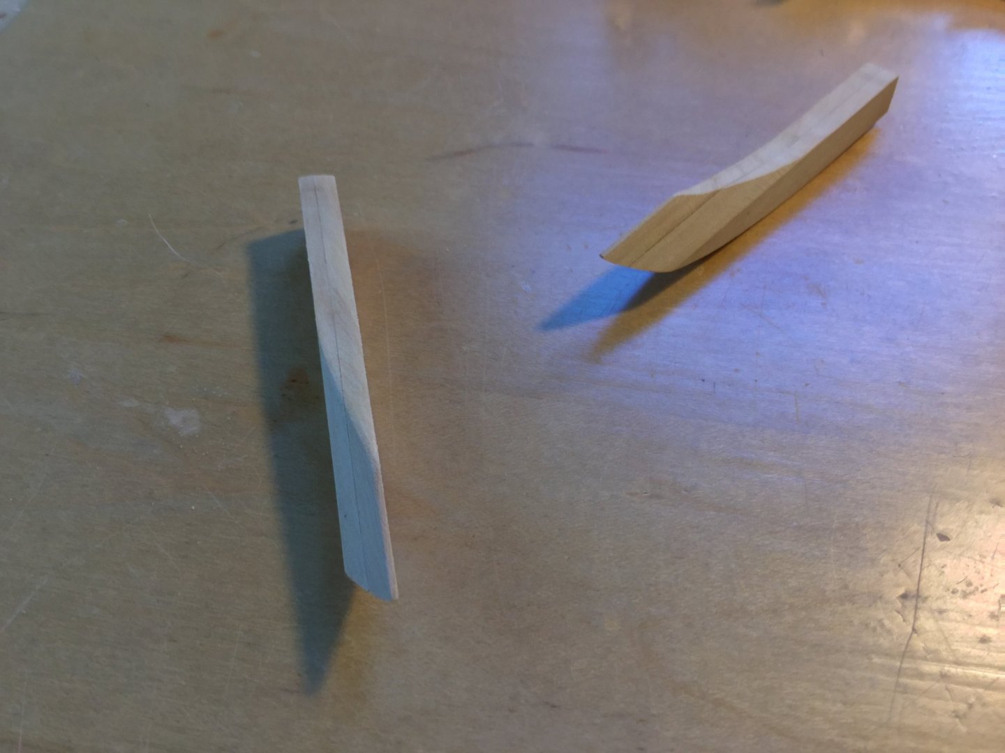
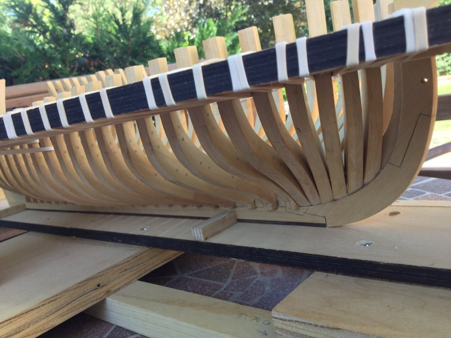
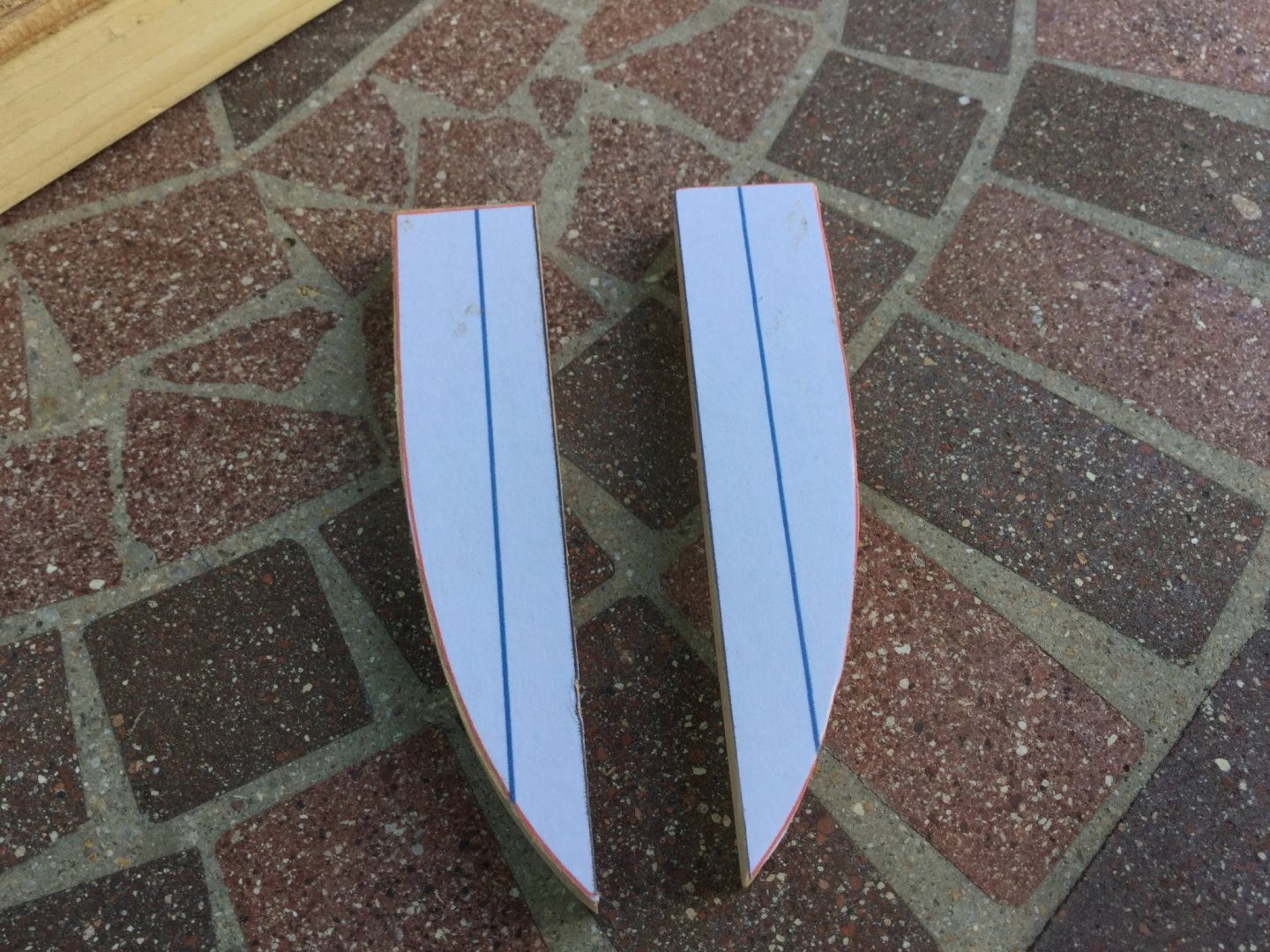
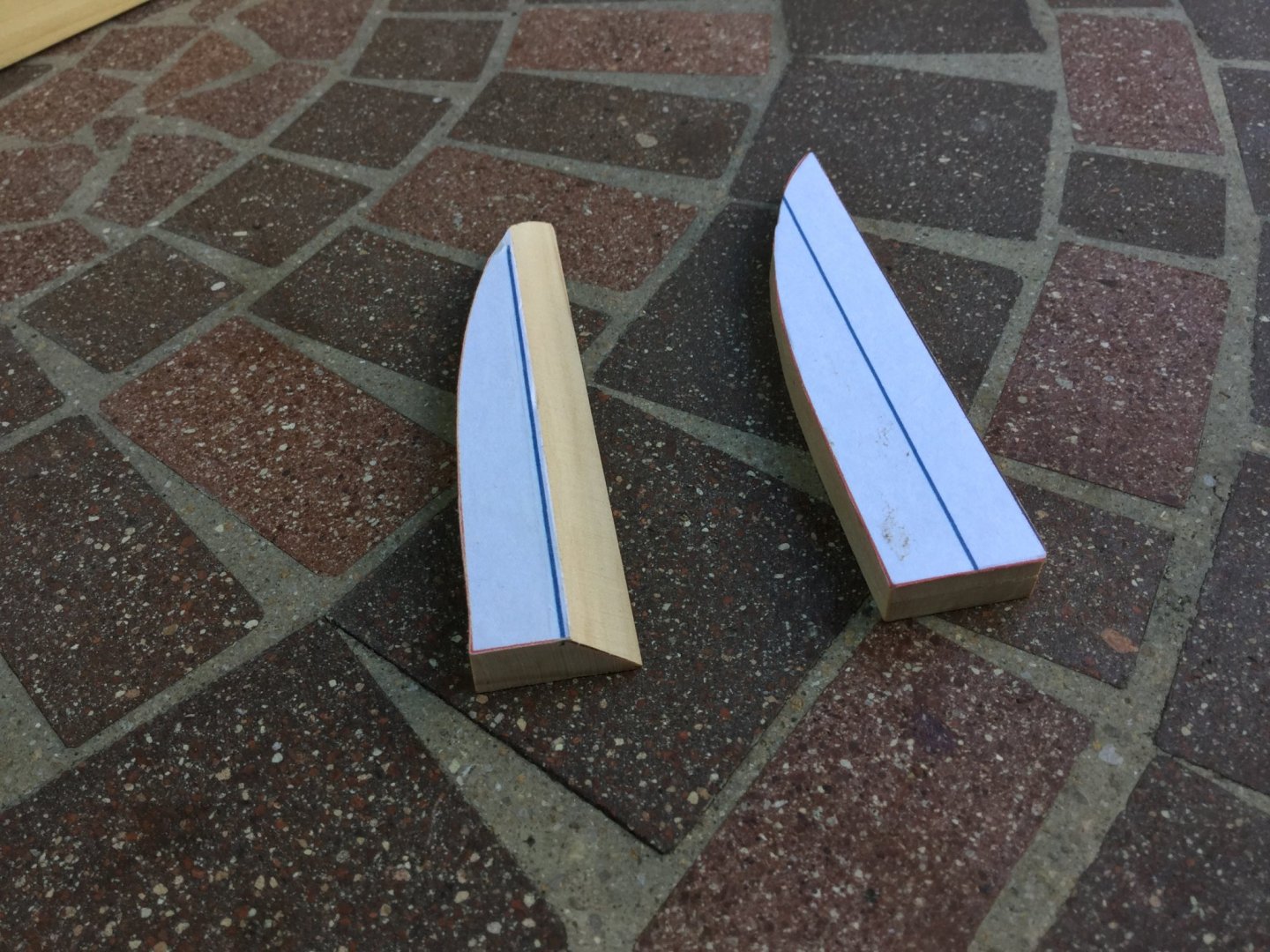
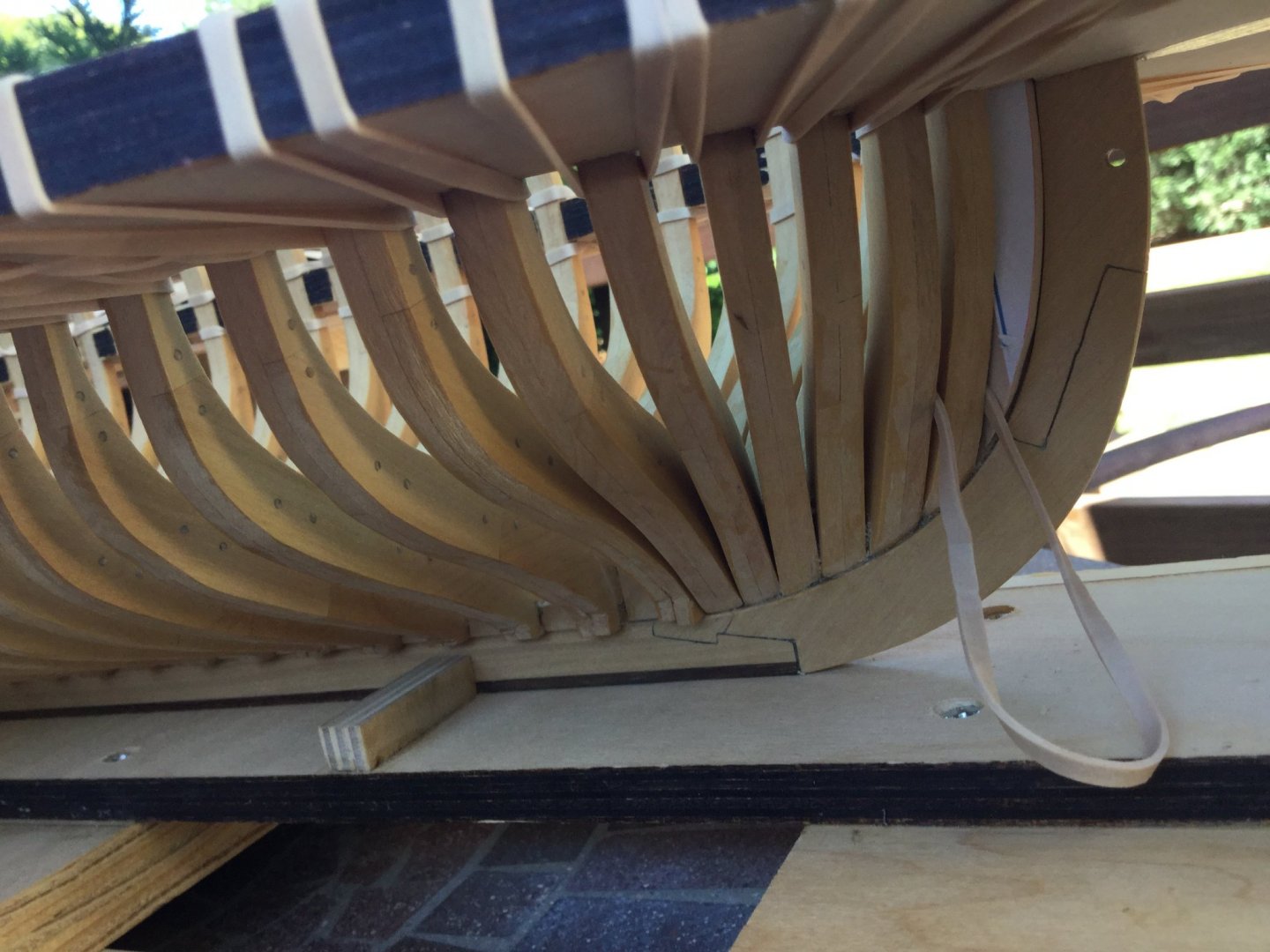
Thanks, guys! Once I was satisfied with the steps to make my practice hawse timbers, I made the real timbers out of the boxwood blanks. I refined the fit and set them in place. You can see that the shape is complex. Take your time with this series of steps. Before I glue the hawse timbers in place, I will shape the outboard surfaces so only minimal fairing will be needed later. There is still a bit of wood to hog off of them.

-
I finished gluing the 6 pair of forward cant frames in place, again using epoxy. Bob Hunt's lofting of the frames is pretty darned good so tons of fairing won't be necessary. I cut out the blanks for the hawse timbers. I made a practice pair out of pine to check the fit. There is quite a bevel and a lot of waste needs to be removed. I'l trim the inside before fairing the inside of the ship. I'll save the outside for later on.


- 45 replies
-
- 12
-

-
Thanks, Rusty! I'll frame it the way the plans suggest. Likely will never find out why it was drawn this way!
- 421 replies
-
- 1
-
-
- granado
- bomb ketch
- (and 2 more)
-
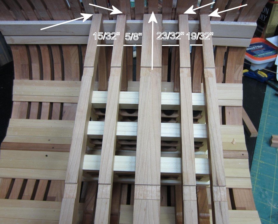
I think you misunderstood, Rusty! I know that the riders straddle the keelson. My question is their spacing along the keelson, which also determines the location of the mortar pit beams. They are not symetrical, and they don't line up withe the frames. Here is what I mean: The photo is yours. The measurements are the spaces between the mortar pit beams for a 1:32 scale model plans. The arrows show that the beams (and therefore the riders) don't meat up with the underlying frames. Notice the far left beam? I6t straddles two frames, while the far right beam overhangs it's corresponding frame.
- 421 replies
-
- 2
-
-
- granado
- bomb ketch
- (and 2 more)
-
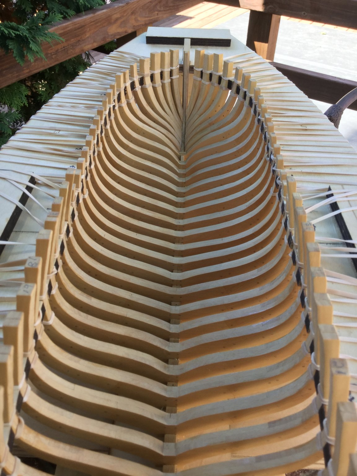
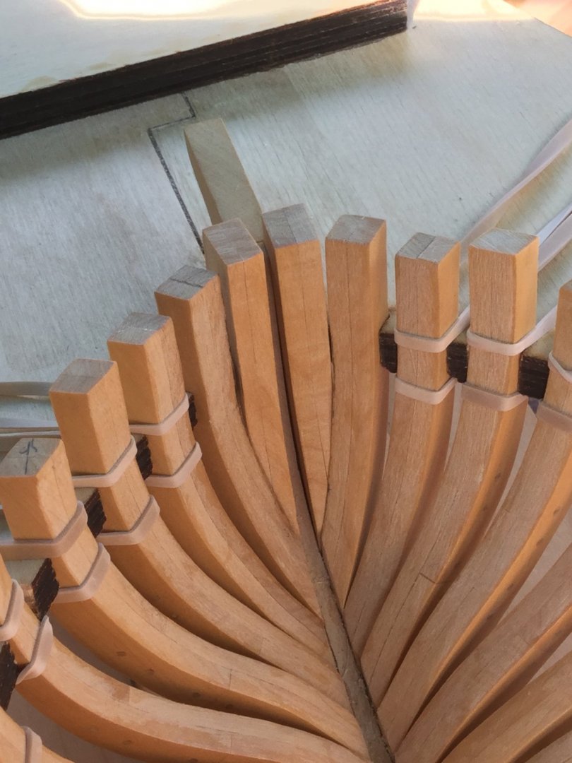
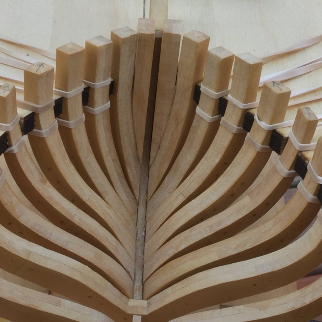
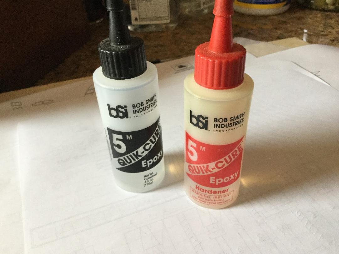
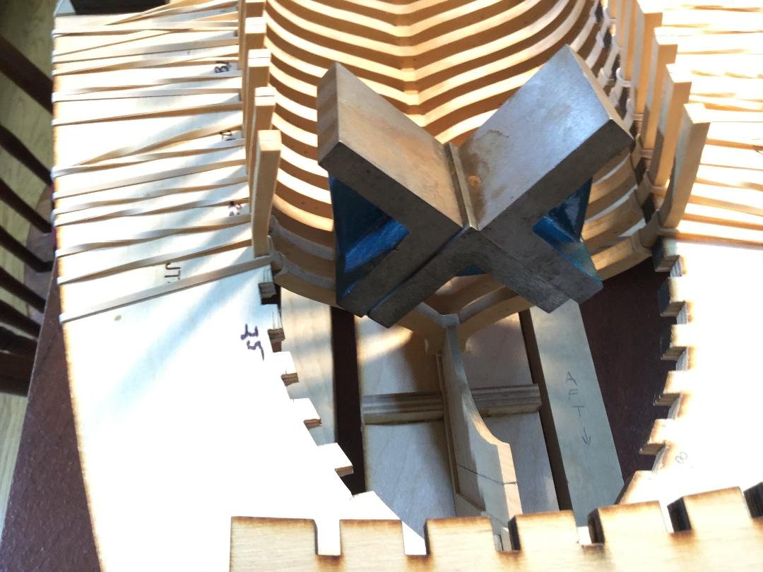
So I finally glued all the full frames (#1 through #23) to the rising wood on the keel. The fit is snug, so no pinning or doweling will be necessary. I do want the hull to be sturdy, so I opted to use epoxy. A problem with epoxy is that once it cures, it's virtually impossible to remove any squeeze out or smears. It often makes a mess, even though the bond is very strong. I like to use Bob Smith Industries Quick Cure 5 Minute epoxy. It has a 5 minute working time and fully cures in one hour. I put a little epoxy in the notch on the frame's bottom the set the frame in place on the "saddle" notch on the rising wood. I weigh it down with machinist right angle blocks for about five minutes. At that point, the epoxy has set up enough that you can't smear it, or draw it out in stringy tendrils like pizza cheese! If you take an X-Acto knife, you can pry away any squeeze out from the wood, leaving no residual. It works well. I then replace the weights and wait till the epoxy fully cure, then move on to the next. Slow going, but this isn't a race! If you plan to use epoxy in a highly visible area, try this technique. But practice a bit first to get the timing right! Next up are the bow cant frames


- 45 replies
-
- 10
-
-
Great job on this build, Rusty! I've had these plans forever, and I'm just now spending some time looking at them in more detail. I've got a question, if you don't mind. In looking at how the frame riders are laid out over the keelson, I noticed that they don't sit exactly over the frames, and their spacing is not symmetrical. Therefore the same is true for the mortar pit beams. Any idea why the plans were drawn this way. Check out post 135 in this thread. Thanks!
- 421 replies
-
- 1
-
-
- granado
- bomb ketch
- (and 2 more)
-
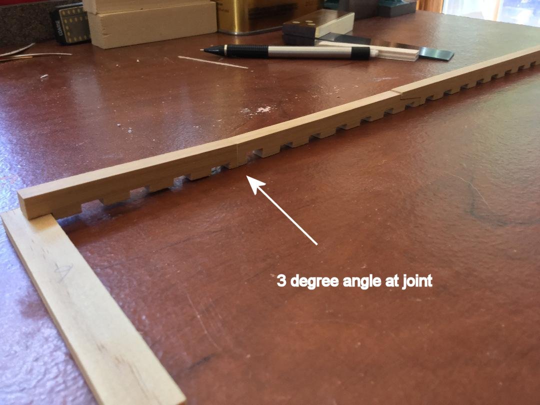
Hi Mike ! Welcome. Actually, the keelson starts to rise in the AFT of the ship over the course of the final 5 full frames. The aft cant frames (5 pain) have no keelson for obvious reasons. On my model the keelson rise is 3-1/2 degrees. My plans are an adaptation of Hahn's plans. If you use the Hahn plans, you should have no keel/keelson issues.
-
I spent a lot of time cleaning up the frames in preparation for glue up. But I also wanted to fit the keelson while I could still remove any frame I needed to for tweaking. The keelson comes in 4 parts: two long ones, joined by a scarf, and 2 "extensions" that transition the keelson onto the dead wood both fore and aft. As I mentioned earlier, the keelson need to rise along the last 5 full frames, but the keelson in the plans is straight as an arrow, with no rise. After much thought I decided to redesign the keelson. My first step was to identify where the rise begins. It turns out that point is between full frames #18 and #19. So I remade the aft-most piece of the keelson in two parts: the straight part and the upward sloping part. After a lot of trial and error, and using a couple of mockup parts, I got it right. The rising portion of the keelson joins the straight piece at a 3 degree angle! Now I can go ahead and glue the frames in place. The keelson is installed after the hull interior is faired. I'll probably simulate a butt joint on the forward long keelson piece, making it look like the long keelson was built up of 4 timbers, not 3.
-
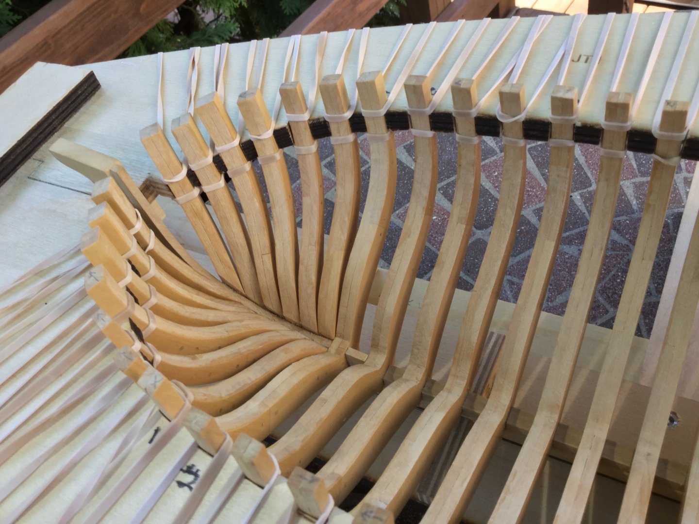
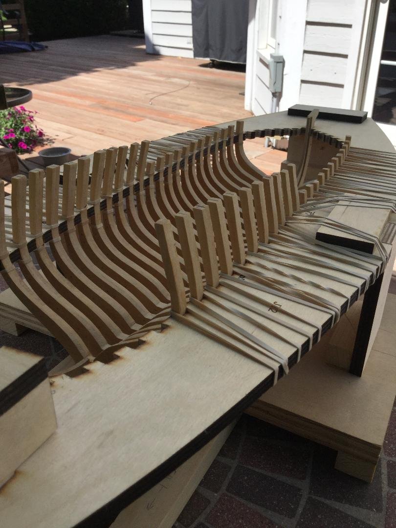
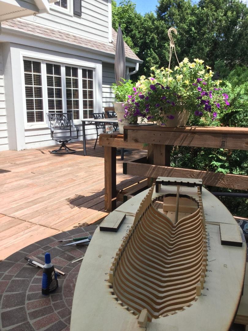
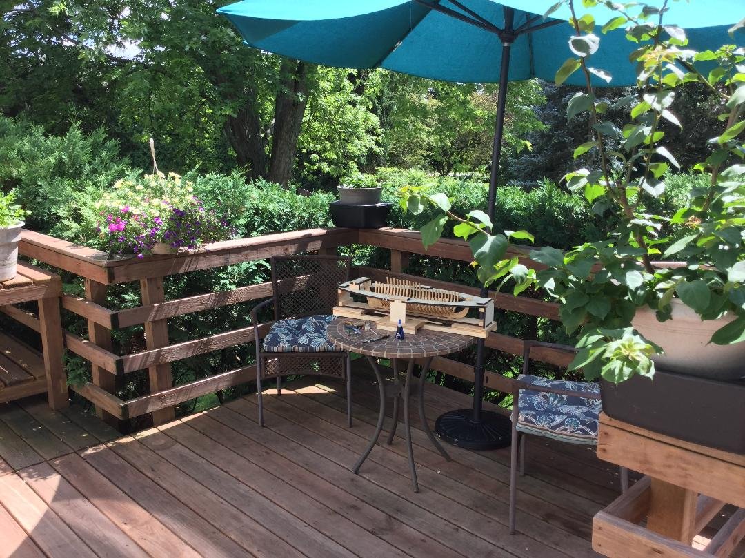
I've been very neglectful of this build, but for good reason. In looking to tasks ahead, I discovered that the plans call for the keelson, which comes in two parts, joined by a scarf to be completely straight and parallel with the false keel. In reality, the keelson has to rise over the last 7 frames or so moving aft. I've been trying to avoid thinking about a resolution, but I think I have one. All the full frames are cleaned up and ready to glue to the keel/rising wood. More stuff coming! One thing I love about summer is that I can move the shipyard out on our deck and enjoy the great weather. Here are a couple shots of my summer work environment!
- 45 replies
-
- 11
-
-
We've all had that sinking feeling in the pit of the stomach at one time or another! I'm sure your fix will turn out fine, Elijah!
- 228 replies
-
- 3
-
-
- gunboat
- model shipways
- (and 1 more)
-
Mario: The “Hannah” is a reconstruction (or reimagination) of a merchant schooner converted to a warship. There is no bottom line here. Build what you want, and realize no one can provide evidence that you are wrong. There is no “official” plan for Hannah. Just what each builder says she is! The guns are your choice.
-
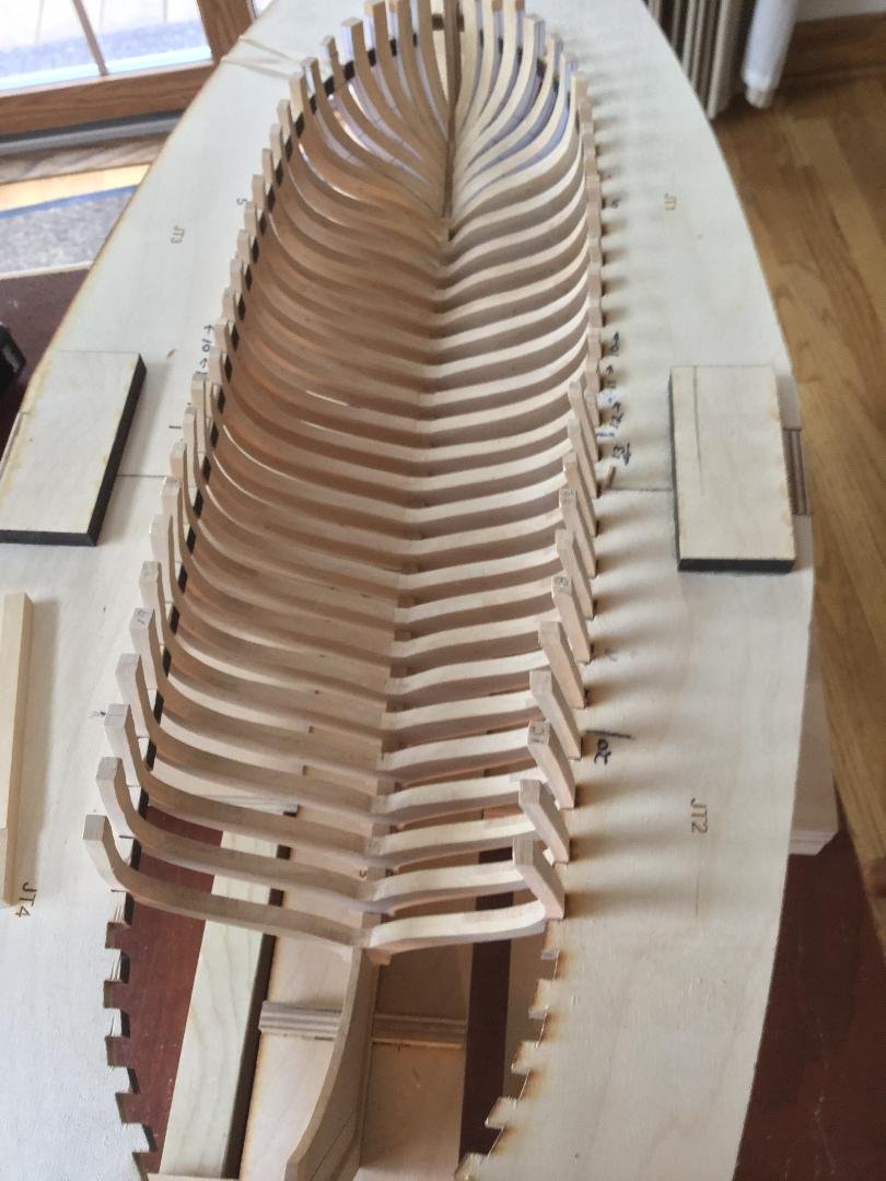
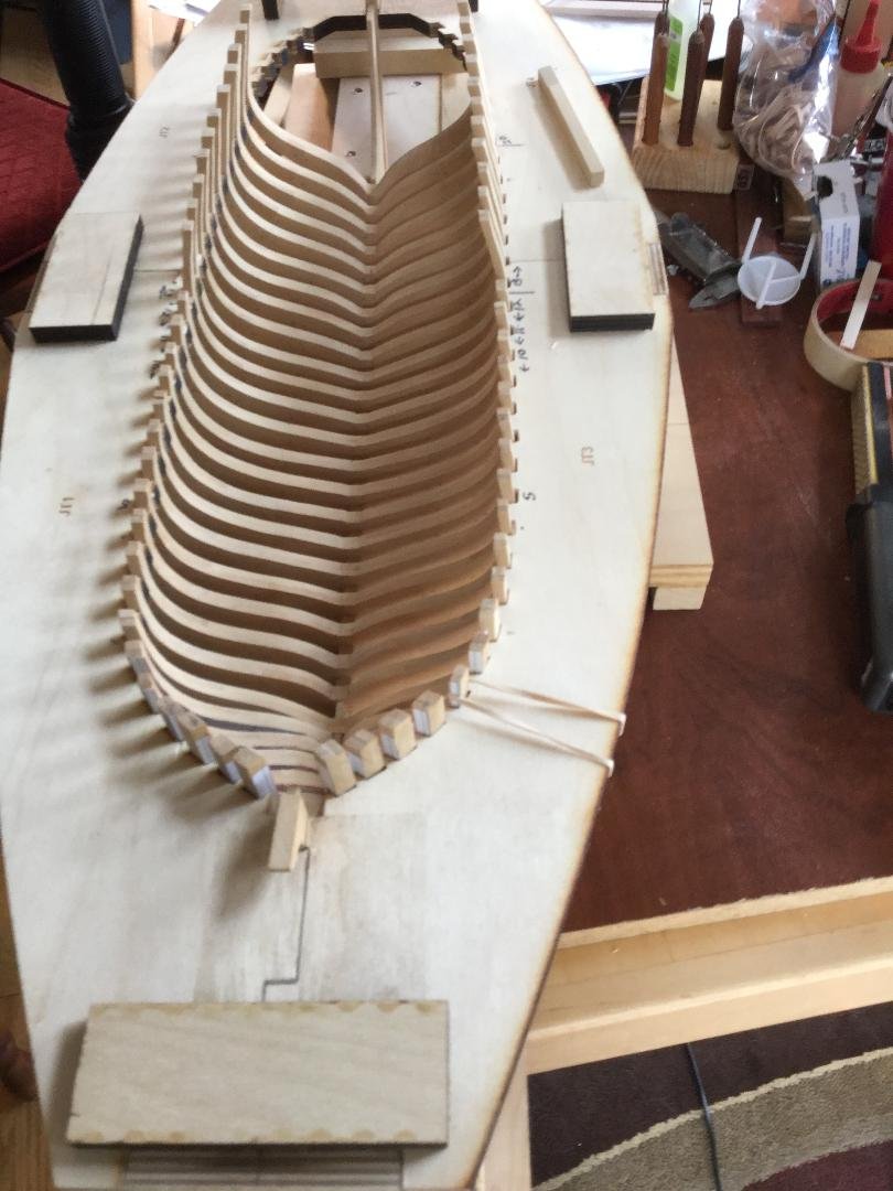
I've been busy prepping the frames, filing the seating surfaces for the keel and keelson flat. I also remade the first three cant frames, which are no longer too short! I also placed the treenails. Not counting the nails that will go into the fore and aft cant frames, there are 800 treenails in the full frames alone! As you can see from the photos, the frame lofting was pretty well done on the plans, so fairing will be easier.Before I glue the frames in place I will give them all a couple of coats of poly on the for and aft surfaces, which will be hard to reach once they're glued in place. I did make one unfortunate discovery. The keelson plans show the entire keelson to be dead horizontal, but the model tells me that the keelson begins to rise at full frame #18 and continues rising until the cant frame begin at frame #24. I'm going to have to design a custom keelson for the model. This will slow things down a bit!

-
Very nice job! Outstanding metal work!
-
Go to post #42 in this thread. Here is the article David refers to: http://modelshipworldforum.com/resources/furniture/Tryworks_Building_Guide.pdf