


DocBlake
-
Posts
1,811 -
Joined
-
Last visited
Content Type
Profiles
Forums
Gallery
Events
Everything posted by DocBlake
-
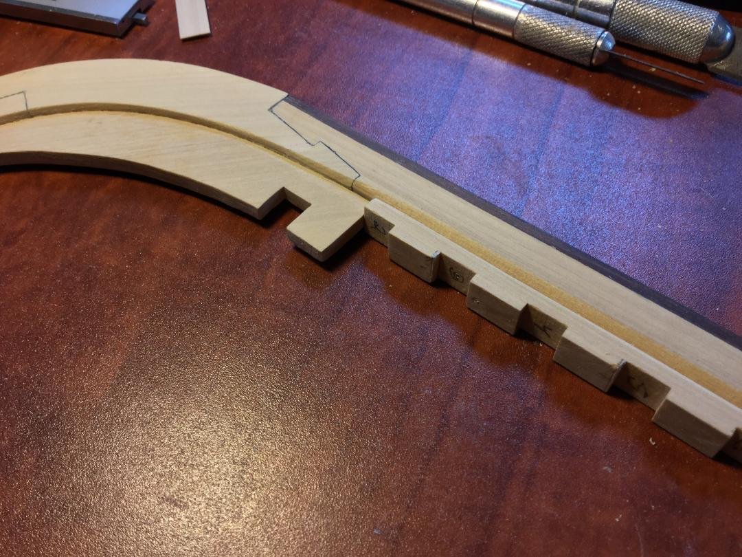
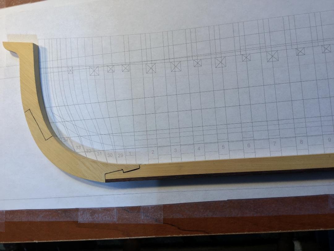
 Thanks, everyone! This model is based on Hahn's plans, but uses an upright jig, unlike Hahn's method. As drawn, the plans leave little extra length in the top timbers to ensure that they can be trimmed to the right height. After fitting the feet of the cant frames to the deadwood, the first three frames came out dangerously close to too short. I weighed my options and decided to remake frames #32, #33, and #34, leaving the top timbers 1/4" longer than the plans.
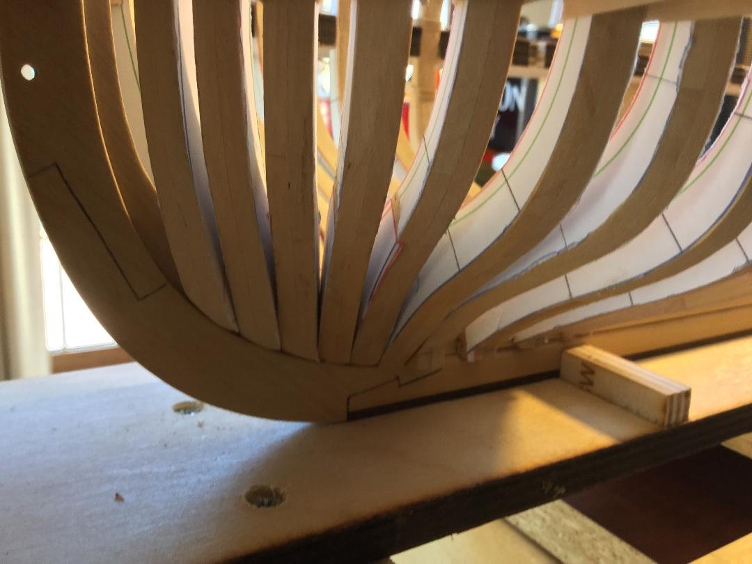
- 45 replies
-
- 12
-

-
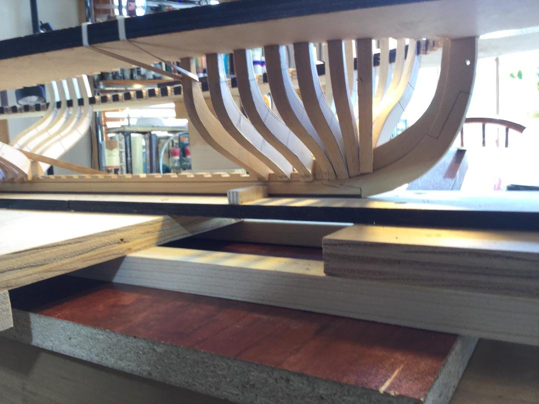
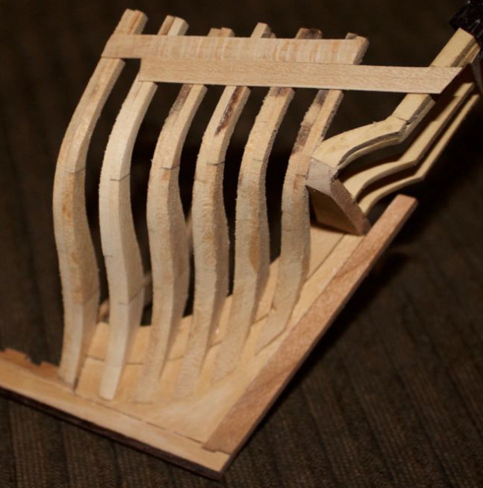
Still at it! Working on frames. I've beveled the cant frames and i'm fitting them to the fore deadwood. Only rough sanded. No bolts or poly. In fact, the futtock template drawings with the bevel lines are still cemented to the frames!

- 45 replies
-
- 13
-
-
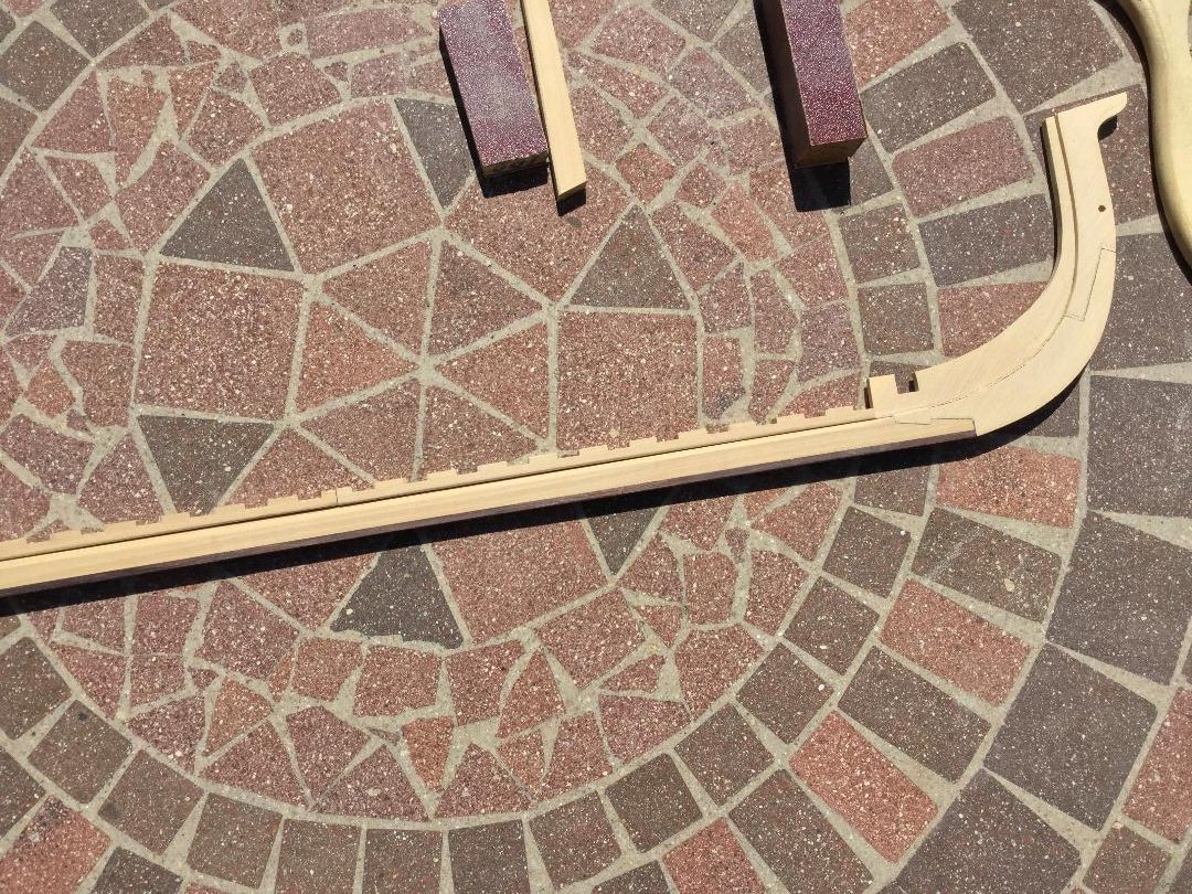
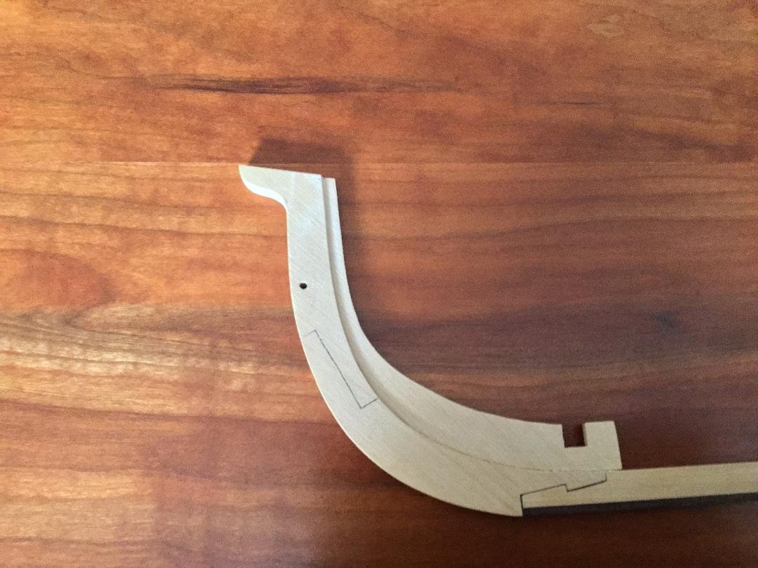
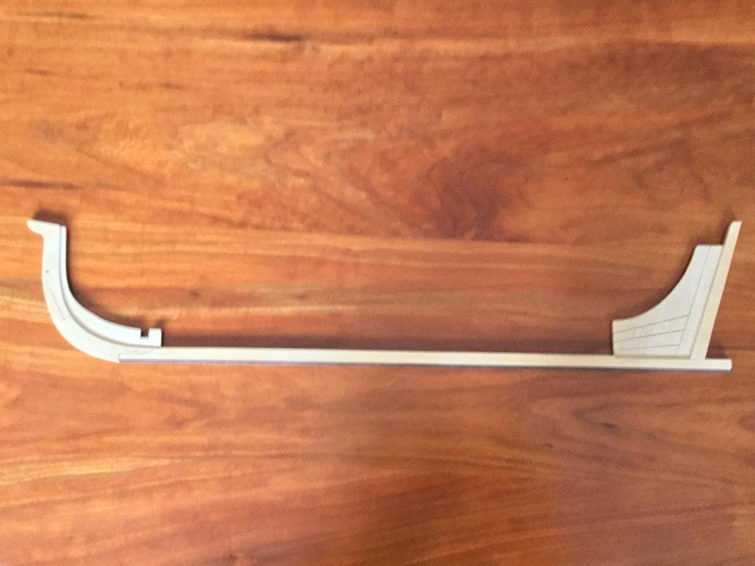
I glued the rising wood to the keel and then smoothed the transition of the rabbet to the stem and stern. At the stem the rabbet changes from "V" shaped to perpendicular to the dead wood. Same at the stern. I also trimmed the keel to length.
- 45 replies
-
- 15
-
-
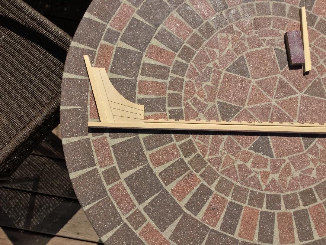
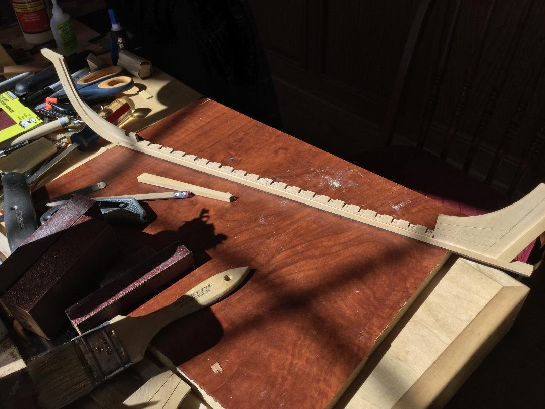
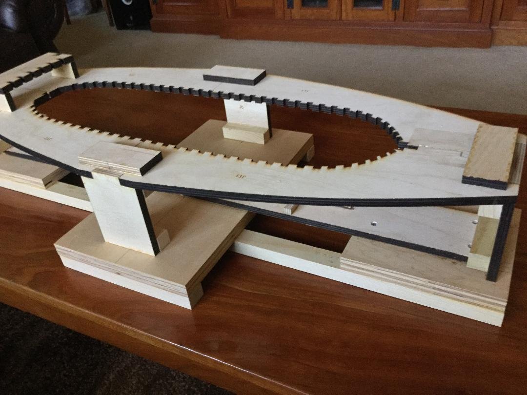
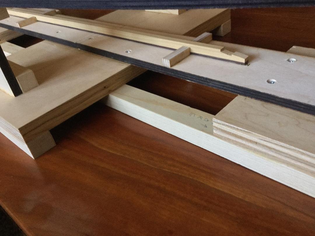
I'm getting close to finishing the keel. The rising wood comes in two pieces. After cutting the notches for the frames, I cut the rising wood to fit, making sure the notches lined up with the frame locations on the plans. The rabbet is next. At the stem, the rabbet is created by the stem and the fore deadwood. There is no rabbet aft. The planking would sit directly on the deadwood aft of the bearding line. The main rabbet along the hull is created by beveling the top edges of the keel and the bottom edges of the rising wood. When glued together, they form a nice rabbet. In the photo the rising not yet been glued in place. Once that's done, the keel is finished.
- 45 replies
-
- 12
-
-
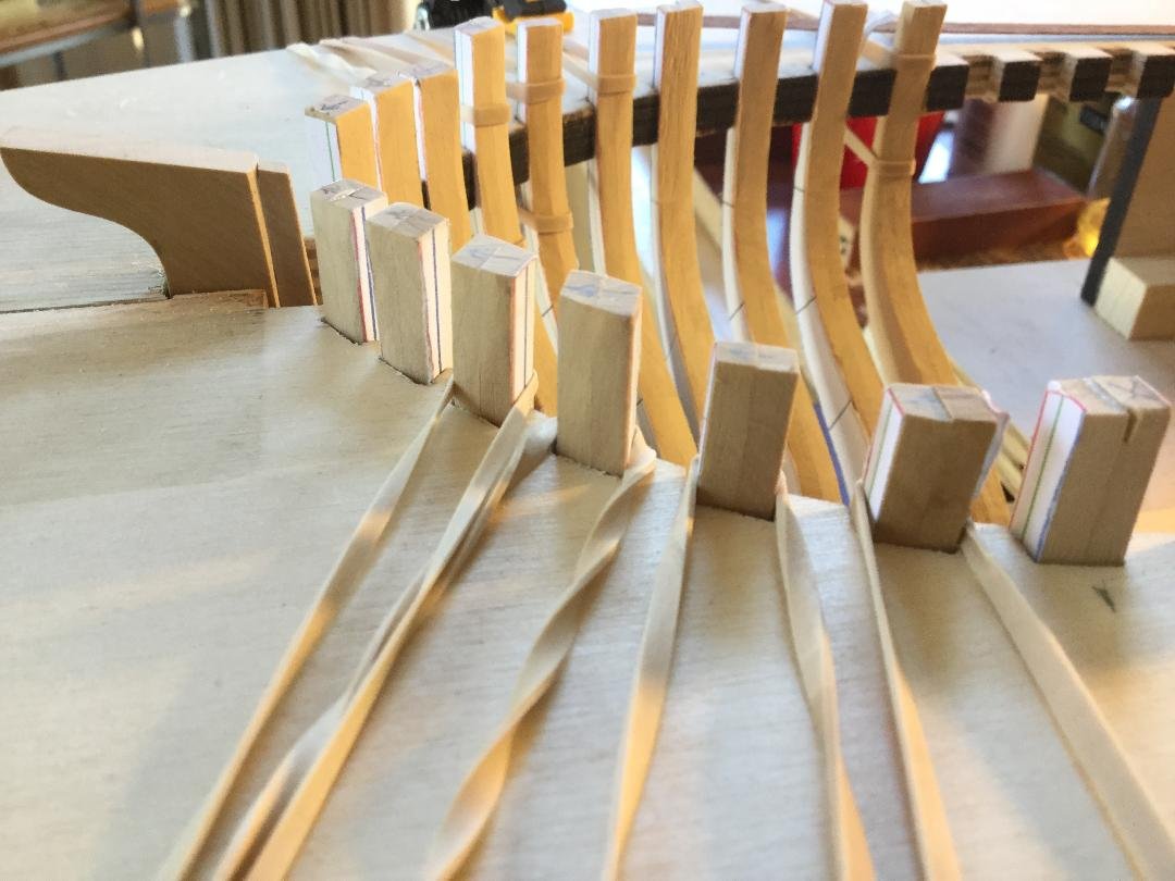
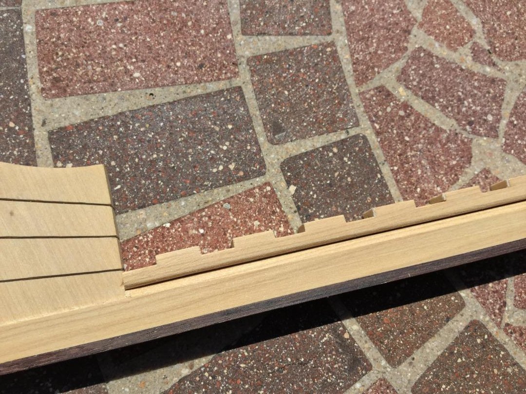
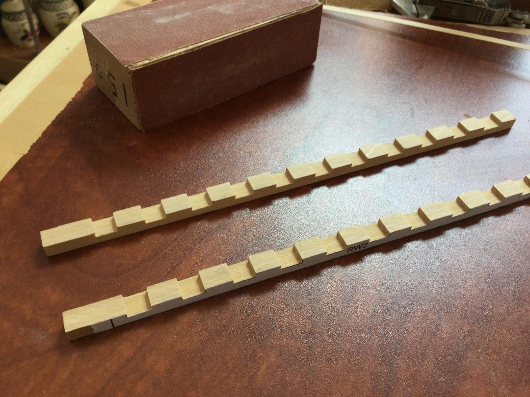
Thanks for the "likes" guys! I cut the notches for the frames into the rising wood blanks using the Byrnes saw and a I-292 .030 kerf blade. They need to be cut to length. Because the plans were scaled up to 1;32 scale, the lines on the plans have some thickness to them. It's a matter of sneaking up on the final width of the notches so the frames fit snugly. Not easy to do! I have a few that will need shimming. Since I plan to epoxy the frames to the rising wood and then pin them to the keel with braass rod, that may be overkill.
- 45 replies
-
- 10
-
-
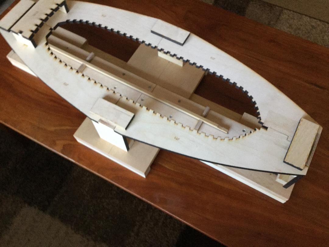
I finally assembled the keel and the deadwood fore and aft. I simulated a build up stern deadwood by cutting grooves into the wood and highlighting them in pencil. Next up is to bevel the top edges of the keel to form the rabbet and then glue on the rising wood.

- 45 replies
-
- 11
-
-
I taped a copy of the plans to a piece of melamine shelving, then put down some double sided tape. After blackening the edges of the scarf joint, I taped the stem to the plans. I put some glue in the scarf, the glued the stem to the scarf, holding it with an office clip and weighing the keel assembly down with weights. Next is the sternpost and the fore and aft deadwood.
-
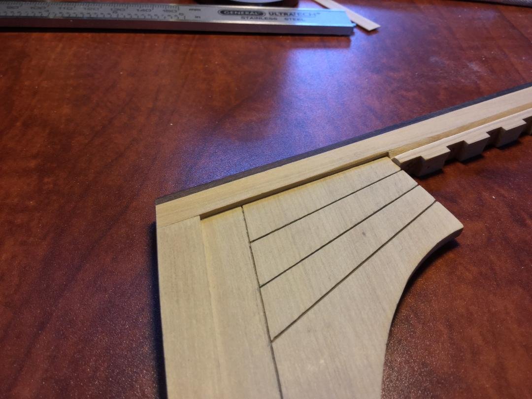
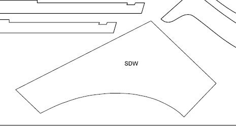
Hi Dave! I haven't purchased any of his books, but I did buy his College of Model ship Building CD's a a special discounted price a number of years ago. Lots of good info there. I began work on assembling the keel. The most important part is getting the stem glued to the keel, and setting the sternpost and the deadwood. I fiddled with the sternpost angle for about an hour before I was satisfied. The first photo shows the relationship between the keel blank, the stern post and the stern deadwood. Before I do any gluing, I need to decide what to do with the deadwood. Both Bob Hunt's plans and Hahn's plans call for this to be one single piece. Given the size and shape I'm sure in real life it was made up of component parts. Any thoughts on a design? I enclosed a photo of the part outline as well as what the deadwood looks like with the stern half frames in place.
-
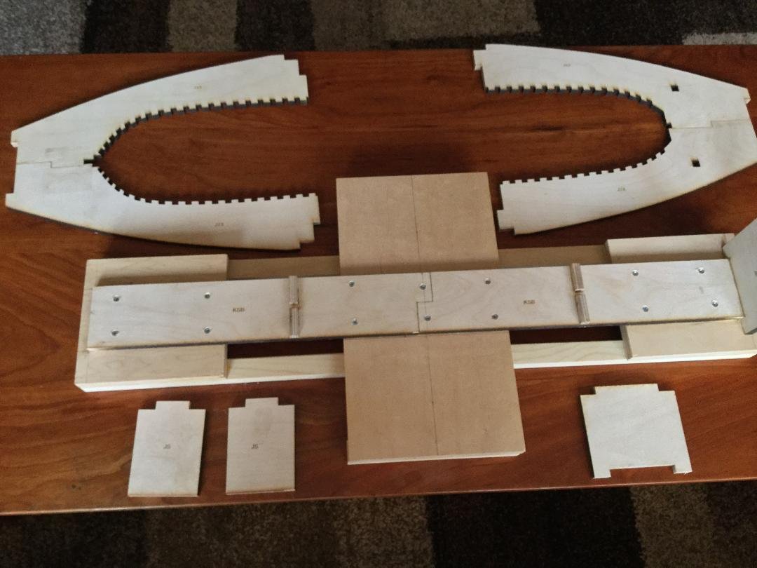
I finished the building jig. The last photo shows the keel blank with the scarf cut into the forward end held in place by the wooden "clamps". Once the keel is placed in the jig, I'll hold it down to the base by drilling some holes on either side of the keel at a couple of locations and fixing it in place with a couple of nylon cable ties.
- 45 replies
-
- 12
-
-
Thanks, guys! Rather that hand cut the building jig, My good friend Mike agreed to laser cut it for me out of some very nice 3/8" Baltic Birch plywood. The base of the jig has a pair of "clamps" that hold the keel straight. The stem and the sternpost fit into notches in the top , as do the arms of the frames. The principle is the same as my Blandford build jig. Thanks, Mike!!
- 45 replies
-
- 11
-
-
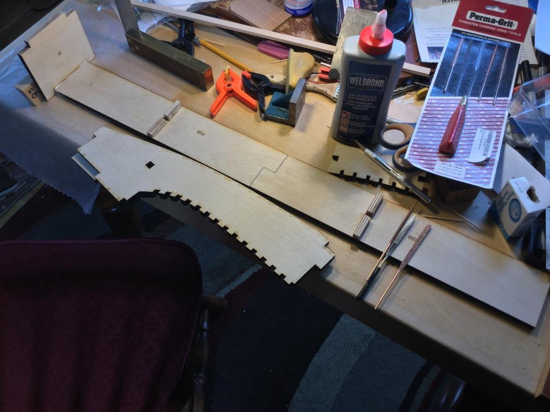
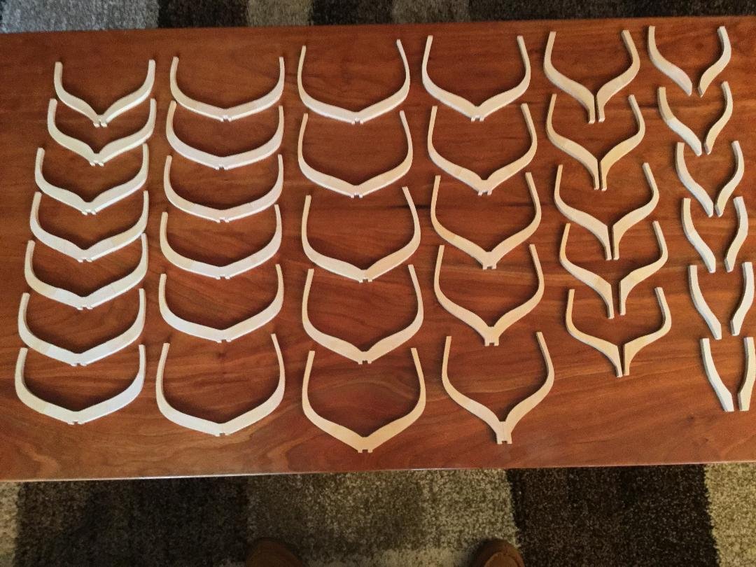
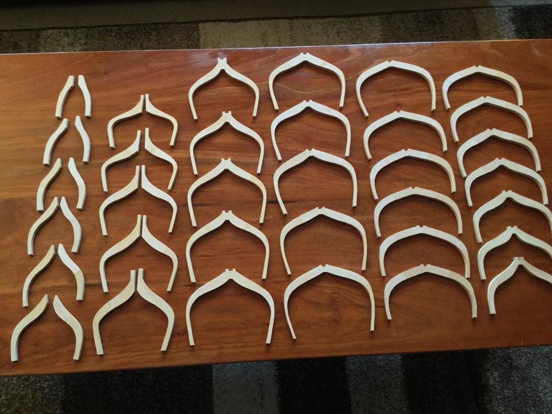
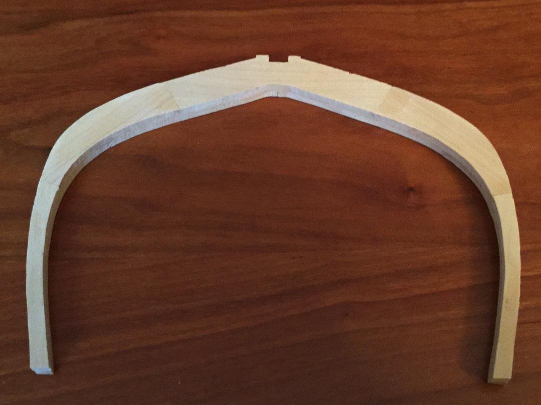
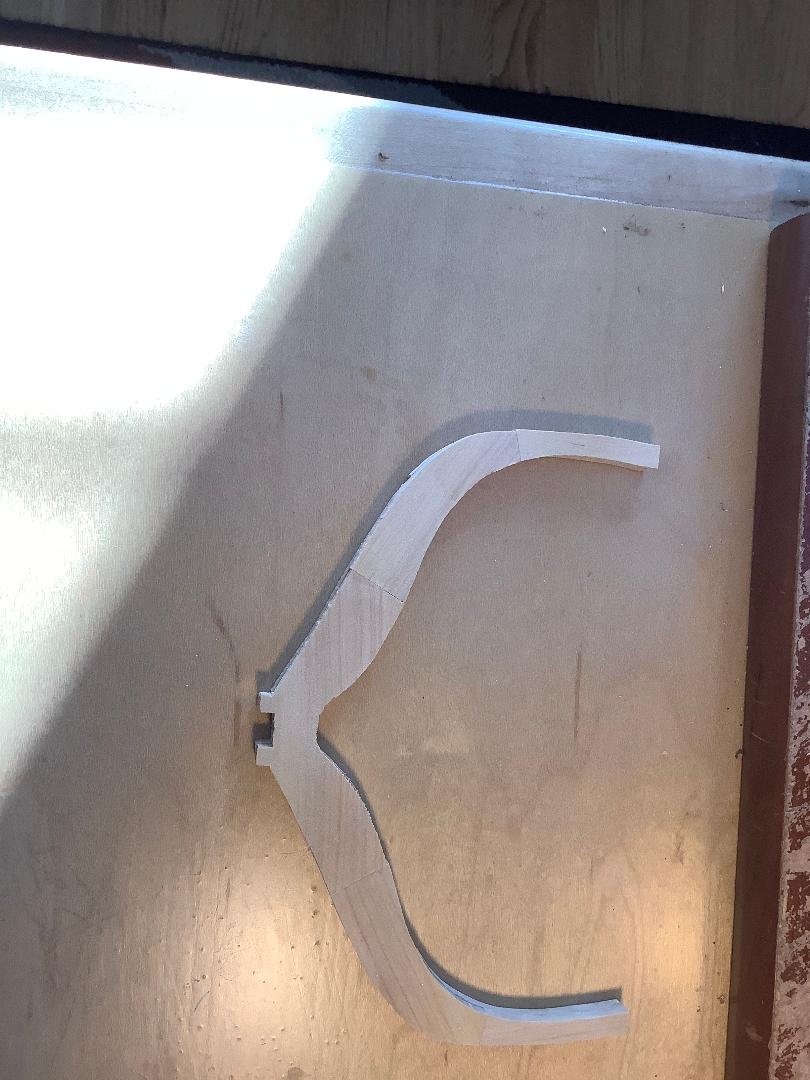
Finally completed all the frames. They are not sanded, beveled nor treenailed. There are over 300 parts making up the futtocks of the frames: 23 full frames, and 11 pair of half-frames and cant frames. All of boxwood. I wore out a dozen scroll saw blades cutting through that stuff. Fortunately the blades are cheap: about $0.50 a piece. The last photo shows a closeup of one of the full frames. I didn't use the Hahn method of cutting them out. All frames were constructed using individual futtocks assembled over a drawing of the frames. It IS possible to get tight joints between the individual timbers using that method.
- 45 replies
-
- 14
-
-
Bench Top 5" Disk Sander
DocBlake replied to DocBlake's topic in Modeling tools and Workshop Equipment
That is obviously true, but I’ve come up with a dozen situations where it is much easier and accurate to have the “slow” sanding surface at the periphery of the disk and not the center. -
HMS Blandford (1720) did not have permanent pin rails. They were lashed to mizzen shrouds and mizzenmast as David pointed out.
-
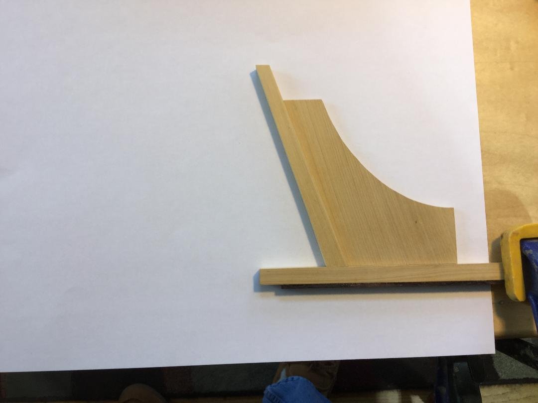
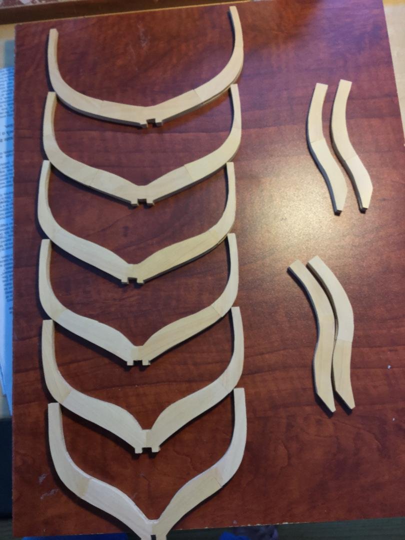
Lots going on, so I'm not posting as often. I started building the frames. They are "sistered" and made of boxwood. The little tabs on the floors of the frames help to strengthen the frame and prevent breakage while handling, finishing and installing them. They are trimmed off after all the frames are installed so the frames flow smoothly into the rabbet, This is a Bob Hunt idea, and it works very well. The frames have not yet been sanded, bevel or finished in any way. Just glued together after cutting from their billets.
- 45 replies
-
- 11
-
-
HMS Pickle by mtbediz - FINISHED - 1:40
DocBlake replied to mtbediz's topic in - Build logs for subjects built 1751 - 1800
Very good work, Mustafa! -
Very nice job overall. I especially love the launching ways! Well done!
- 231 replies
-
- 1
-
-
- model shipways
- armed virginia sloop
- (and 1 more)
-
CNC wood carving
DocBlake replied to cafmodel's topic in Painting, finishing and weathering products and techniques
Very nice. CNC is revolutionizing the hobby. -
HMS Pickle by mtbediz - FINISHED - 1:40
DocBlake replied to mtbediz's topic in - Build logs for subjects built 1751 - 1800
Great job, Mustafa! Very nice model! -
These plans were originally drawn in 1:48 scale, and we enlarged them to 1:32. The result was some thickening of the part outlines, and the problem will be "tolerance creep" unless I'm very careful. I've already had to remake the stern post! Oh well, these are the challenges of scratch building.
-
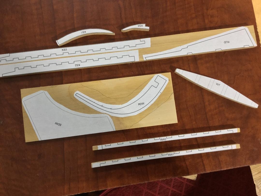
Getting ready to make a little more sawdust. Templates for various parts rubber cemented to their boxwood blanks. Shown are the rudder, wing transom, 2 part rising wood, 4 part keelson, stem and stern deadwood and the sternpost. I'm trying to align edges where straightness is critical to the straight edge of the blanks.
- 45 replies
-
- 11
-