Gregory
-
Posts
3,168 -
Joined
-
Last visited
Content Type
Profiles
Forums
Gallery
Events
Everything posted by Gregory
-
That is a very low end machine.. 85 watts. It burns up because people try to get off cheap then use it for jobs it is not designed for.
-
 Looks really good!
 -
Very much so. The Proxxon has a micrometer style fence adjustment that makes it superior to the MicroLux in that respect. A plus for the MicroLux is the variable speed, but I prefer using the Proxxon. If you get either one of them you will want to get this arbor adapter so you can use a lot of 3rd party blades with1/2" arbor. The Proxxon and Microlux blades are way over priced. I get my blades at Malco Saw Company. There are also compatible blades on Amazon with the 1/2" arbor. If you need more info just ask.
-
I had the Microlux/Micromark saw before I acquired the FET , and I'm pretty sure the Proxxon wasn't available at the time, over 20 years ago. I would suspect that Proxxon looked at the Microlux and refined it a bit. They may have even had some kind of collaboration going on. P.S. Just saw somewhere that the Proxxon and Microlux are made in the same factory in Japan, so I believe they probably share some components.
-
Experienced modelers won't be interested, but there are lots of beginners who will be all over this.
-
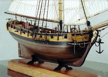
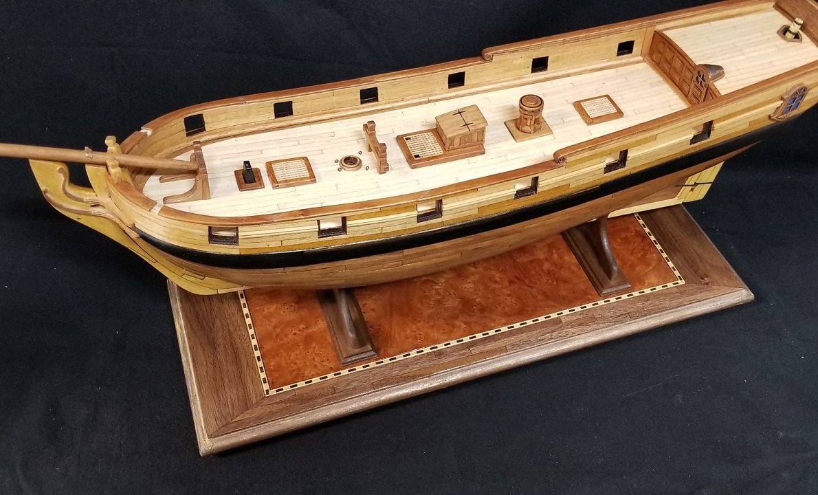
Thanks much for the compliment. That's from my Resolution build. You can click in my signature. It's on hold since the cat thought it was a toy.. Nothing that can't be fixed, but it sort of took the wind out of my sails on that project.. The stem, keel and rudder is yellow heart. Lower hull planking is walnut veneer. The deck is from maple veneer that I cut with a laser, which also gives the caulking effect. Deck furniture and masting is cherry. The exception to my "no paint" preference, is the stove pipe. The wales were done with black ink and the gunports were done with red mahogany stain. Here is a wider shot of the hull.
-
When I'm working on my models, I think of it as playing with my toys, so yeah; to each his own..😁
-
I can't add much too what Barkeater says, and I am in full agreement with him. Those exotics can be really hard on tools, but that said, Ocooch Hardwoods is a great source for dimensioned exotics and domestics. Also, stores like Rockler are a great source for veneer. I like veneer for spiling rather than going the edge bending route..
-
@mugje Have you considered using veneer to make planks. Stores like Rockler have a good selection of maple..
-
CNC Desktop Router Reviews
Gregory replied to tmj's topic in CAD and 3D Modelling/Drafting Plans with Software
What carving software is everyone using? I have been looking at Vcarve and/or Meshcam .. They both look very robust, and they have less pricier versions that should meet the needs of a hobbyist. -
CNC Desktop Router Reviews
Gregory replied to tmj's topic in CAD and 3D Modelling/Drafting Plans with Software
You may have picked up on this in another discussion, But this Kevin Kennedy guy has some great Fusion 360 tutorials. I'm slowly working my way through them. From lesson 1, I have learned about features I may have never stumbled upon by myself.. -
Great Photo Etched Saw Blades
Gregory replied to kurtvd19's topic in NAUTICAL RESEARCH GUILD - News & Information
Here is a link to the wood handle at UMM-USA https://umm-usa.com/onlinestore/product_info.php?cPath=21_28&products_id=35&osCsid=f9dc1861e067b4dd5620358510e5bd49 A variety of blades and other cutting tools here: https://umm-usa.com/onlinestore/index.php?cPath=21_28&osCsid=f9dc1861e067b4dd5620358510e5bd49 P.S. I was going through my ship modeling bookmarks and discovered this: 30 Years Anniversary JLC Micro Saw Pack I forgot I had bookmarked that and never got around to ordering it.. I will, now. Looks like a great value at $22.95 . -
Great Photo Etched Saw Blades
Gregory replied to kurtvd19's topic in NAUTICAL RESEARCH GUILD - News & Information
What is the actual name of the tool for the purpose of searching on Amazon? -
OK, my mistake. The word " pen " did not compute for me.. I haven't actually tried the pens, but I don't see them as a useful modeling tool. I have small cans of stain that I bought ten or more years ago.
-
My experience with them is that they are just wax crayons.. They work up to a point, but I think you would do better to work with some of the original stain.
-
You might look at some of the Cheerful logs, as well as Chuck's instructions, available on the Syren website. Chuck references several sources, including the contemporary model. There are several contemporary models in the gallery. You are doing a great job.. Don't get bogged down in minutiae..
- 562 replies
-
- 2
-

-

-
- vanguard models
- alert
- (and 2 more)
-
What are the dimensions of your brass piece? Do you plan on using the outside of the frame, and just replace the small square panes?
-
Looks really great, and makes me feel better about not getting much done in the last few months.
-
Calculating rope thickness (Fictional ship)
Gregory replied to Harry12's topic in Masting, rigging and sails
Harry12, I wouldn't be obsessed with precisely following the establishments for 17th century ship rigging. There is always the rule of " what looks good, is good " .. Take a look at some of the contemporary models in the gallery here.. Gallery of Contemporary Models from Museums and Private Collections Try to maintain a sense of proportion. The standing rigging will be heavier on larger masts, and will get smaller the higher up on the masts. For the running rigging; heavier on the larger yards, and getting lighter as it goes higher. The rat lines are probably the smallest ropes, and something modelers often make too large. I like to go to Chuck's Cheerful as a great example of rigging that looks proportional. While your three masted ship will have a lot more lines, the principles of look and proportion will remain the same. -
Calculating rope thickness (Fictional ship)
Gregory replied to Harry12's topic in Masting, rigging and sails
Full size is the size of the actual ship.. If you are working in a scale of 1:12, 1 inch on the model would be 12 inches' on the full size ship. If the full size rope circumference is 4 inches, then it would be 4/12 = .333 inches on the model. for diameter, divide circumference by 3.14 Are you working from plans, or just pictures, and have decided on a size for the model? -
Calculating rope thickness (Fictional ship)
Gregory replied to Harry12's topic in Masting, rigging and sails
If you are able to enter data, then you would have entered your scale on the strt page. With this in mind, all measurements you enter would be full size. -
I got the little 8mm blade. Want to see if it helps making molding strips and other details, and because it's hard to resist pretty little tools.
-
@gwish Thanks, you just cost me a hundred bucks.. Couldn't resist..😁
-
Don't want to clutter up your log, but how did you get the elephant and lion shots? Are they telephoto? In any event, they are stunning!
- 840 replies
-
- 3
-
-
- winchelsea
- Syren Ship Model Company
- (and 1 more)