
Gregory
-
Posts
3,173 -
Joined
-
Last visited
Content Type
Profiles
Forums
Gallery
Events
Everything posted by Gregory
-
 The circled ports would have no lids. I'm not sure about 1 or two more forward and aft. It would depend on intervening bulkheads. In the absence of bulkheads, the free movement of air and water would be desirable.
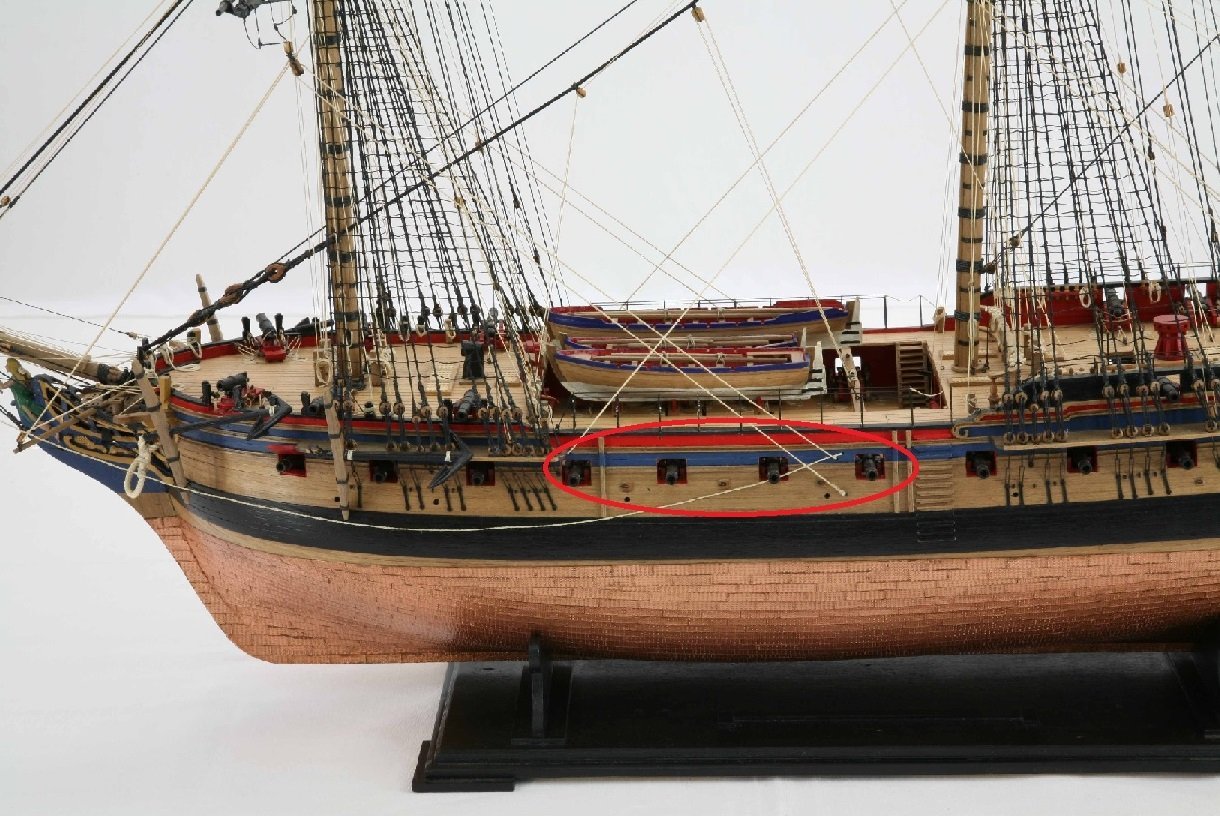
-
Gunport lids served no purpose on a weather deck. The enclosed spaces would benefit from them.
-
Are the masts glued in place. If not, you can use the stays to achieve the desired rake. To affect the run of the ratlines in a noticeable way, the amount of rake would have to be substantial. On the plans, measure the angle between the mast and the deck. It's then fairly easy to make a template to match the angle.
-
Do the plans not show the angle/rake of the masts?
-
Did gun crews dress like that? I'm thinking some noble/aristocrat had himself painted as part of a gun crew..
-
I think Allan nailed it with "artistic license "..;
-
P.S. Allan, I thought you might like this picture. A triple block on the outhaul tackle, and two double blocks on the training tackle. 😁

-
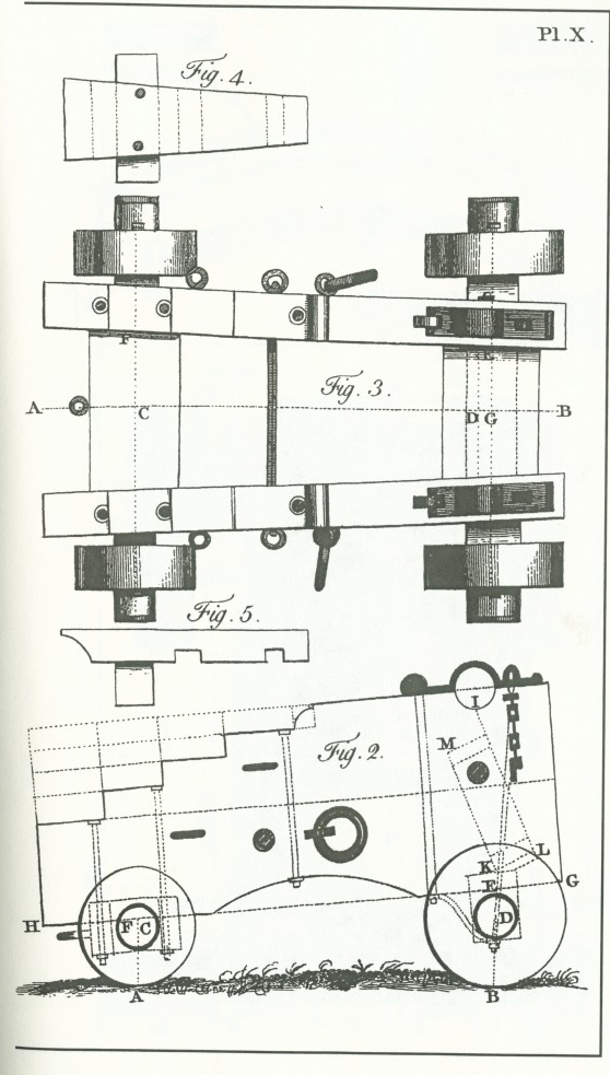
Here is a contemporary drawing from 1775. Found here.
-
Allan, That particular drawing does not even include the extra ringbolts and other details often seen on the carriages. It doesn't seem to be a good example.
-
For moving onto or off of the ship?
-
Books to learn Fusion 360
Gregory replied to allanyed's topic in CAD and 3D Modelling/Drafting Plans with Software
Thanks Allan for starting this topic and thank @mgdawson for the Kevin Kennedy reference.. Was able to start feeling comfortable with the interface after the first video.. Fusion 360 has there own tutorials which are a great way to explore the capabilities of the program before trying to use it. https://help.autodesk.com/view/fusion360/ENU/courses/ -
If I may? A deadeye without holes is not a deadeye...😁
-
Great new model Chris! Just for reference there are some pictures in the Gallery of a contemporary Trial model.
- 57 replies
-
- 10
-

-
- Trial
- Vanguard Models
- (and 1 more)
-
Those hinges do look great! There was a time when making them yourself would have far surpassed anything available aftermarket, but not anymore.
- 840 replies
-
- 3
-
-
- winchelsea
- Syren Ship Model Company
- (and 1 more)
-
A very nice model! Makes me feel better about taking my time..
- 152 replies
-
- 3
-

-
-
- rattlesnake
- Model Shipways
- (and 1 more)
-
Allan, my point was, when someone asks for help bending walnut, suggesting they use a different wood is not really any help with the problem if they would prefer to use walnut.
-
Yes, but if someone wants to use what came in the kit, we should help as best we can without telling them their only option is to buy something else.
-
I would venture over 90% of the builds at MSW are are kits and many of them relative beginners, who may not be inclined to go to a lot of additional expense beyond what they paid for a 'crap kit. Fortunately they do get a lot of help, instead a load of crap from someone who seems to offer a lot of advice, but no real help with regard to overcoming a problem with what they have at hand.
-
There are some drawings of an Endymion at the WIKI Commons, but they look nothing like the model. https://commons.wikimedia.org/w/index.php?title=Category:Ship_plans_of_the_Royal_Museums_Greenwich&filefrom=DISCOVERY+1901+RMG+J7441.jpg#/media/File:ENDYMION_1797_RMG_J5174.jpg
-
3D orienting of ship blocks in Rhino
Gregory replied to Waldemar's topic in CAD and 3D Modelling/Drafting Plans with Software
That is really great work. Would it be possible for you to make a .pdf available for this image? This would be for my private use. I can PM you if you would prefer to keep it out of the public area I know you have invested a lot of time and resources, and I really appreciate it. Gregory -
I've decided I'm going to do a lot of topside work before proceeding with the lower hull.. Does anyone know a good reason for doing all the hull planking first, other than "that's the way it's always been done.".?
-
From what I can Google, scale may be 1:50 . P.S. It appears they made a kit that was 1:50. Can't be sure if your plans are 1:1 from the kit..
-
What is your reference for the numbers you have? The kit manufacturers typically give a height for the finished model.
-
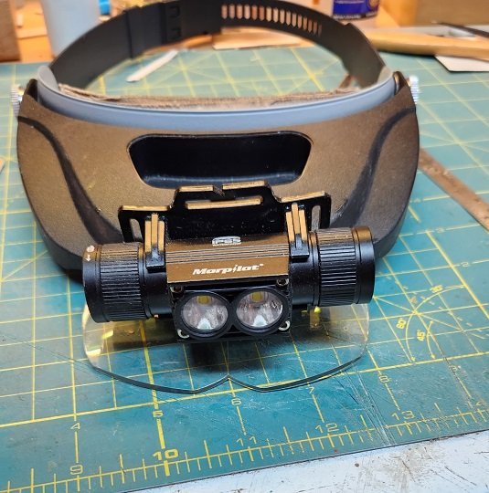
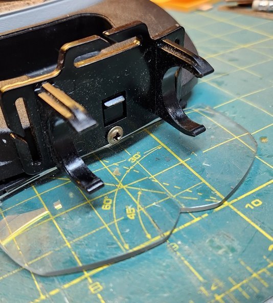
While we're at it, here's my version. The light has 3 intensity settings, and the dimmest is usually adequate for my work. It works for a couple of hours on a charge, and I have two of them, so that one is always charged up. This particular model doesn't seem to be available on Amazon right now, but they have similar ones. The headset is the Carson Pro Series .
-
We have a member, Doris who hasn't been active in a while, but has made some incredible card models. Here is where she shows some detail of her cannon making. Click on the arrow in the upper right of the image above to see her method. Make sure you click through her logs to see some incredible work.

