Thukydides
-
Posts
1,363 -
Joined
-
Last visited
Content Type
Profiles
Forums
Gallery
Events
Everything posted by Thukydides
-
 Fantastic job Jacques. It has been a pleasure to follow along though I only joined late in the process. I always appreciate some good speculative research. I personally think that there is something very exciting about compiling what little info there is on lesser known subjects and bringing them to life. All in all a great build and a very informative build log.
 -
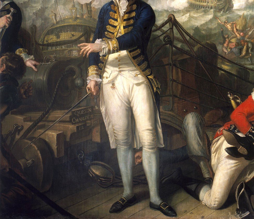
Log #13: A Research Rabbit Trail I have been casting my net a bit wider in an attempt to reconcile some of the issues we have been discussing here regarding gun carriages. As I mentioned one of the main goals with this log is to bring those of you following along on a journey through my research, I thought I would open the door a little on what this looks like for me on a practical level. Having exhausted (at least as far as I can tell for the moment) all of my leads that deal directly with guns and carriages, I decided to start looking for sources that might incidentally mention / show them. I started by searching for paintings from the period which depicted deck scenes. In doing so I came across the following very interesting painting (I have cropped it to the parts I am interested in and increased the exposure a little): The painting is of Lord Howe at the Battle of the Glorious First of June 1794. Now I have to do some more research to confirm this fact, but the RMG description says that the painter: This implies a degree of care and accuracy about the scene which makes it very interesting for research despite the fact it is about 15 years after the time period I am concerned with. In particular you can see the following interesting details about the gun: It appears to be a Bloomfield 12pdr based on the breeching loop and the label on the stool bed. The Queen Charlotte carried 12pdrs on her quarterdeck confirming this detail. The name of the ship is written on the quoin, this may be an extra embellishment added by the painter, but given the care he took to get everything just right it is possible this writing did exist on the gun. The carriage is painted a brown/yellow color similar to how the current carriages on the Victory are painted. This is in contrast to the bulwarks which can just be made out in the background as being a brownish red. The breeching rope appears to be hawser laid. The tackle at the rear of the gun is a double block. This matches what I have found in my research (12pdrs and up had single double combos), but runs counter to what Caruana says. It is a similar colour to the carriage. The strop for the block appears to be served. The stool bed has a slot which the quoin fits into allowing it to slide along. This makes a lot of sense to me from a practical perspective, but I have never seen this in any of the plans or other drawings. Edit: I also just noticed how the eyebolts are countersunk like the example Gregory posted. The next step is then to carefully go back through all the other primary documents/pictures/plans I have acquired to see if any of these details are mentioned or implied. Often I find when I go back I notice things that were just mentioned in passing that I missed the importance of. These other sources in combination with more research into the artist will allow me to judge how reliable I treat these details as being. Then comes the question of if there are accurate, do they also apply to the 1780s?
-
She really does look lovely Eric.
-
I also have seen that one. It is from Robertson's Mathematical Instruments. The carriage in question likely dates from somewhere between 1755-1766, but as carriages didn't change much from 1732 to 1787 (with the introduction of the Bloomfield gun) the dating is not super relevant. The funny thing with that one is that the top bracket (in the plan view) clearly has the steps perpendicular to the centerline, but the bottom it is less certain (though this may be due to distortion from the scanning). The Thorsminde example does seem to show the steps as perpendicular though it is pretty worn... I suspect your are correct, I would just like to be a bit more definitive than "suspect" :). The drawings in question I believe were all drawn in the early 1900s documenting the ship as she existed at the time right before they started a major restoration. One would imagine that the gun carriages would have changed little, but it is not definitive enough to make me comfortable. Most model examples I have found from the period seem to be perpendicular to the brackets (though it is hard to be sure from the pictures). That being said this is a pretty minor detail so it is not out of the question that they were just simplified when making the model. Thanks everyone for all the suggestions. I think I will have to do some more digging. Every now and again I find definitive answers, but so much of this research is sorting through numerous historical examples, evaluating them and then justifying the conclusions on the basis of preponderance of the evidence.
-
Check out the below plan from RMG (typical of my question). No date is given but based on the design I am pretty confident this is a mid to late 18th century carriage. I have labeled the elevation to indicate the parts I am talking about. The brackets are the big pieces that make up the sides of the carriage. Now if you look at the plan just to the right of this you can see that both the steps and the ends are drawn with straight vertical lines (perpendicular to the center line of the carriage). I have seen many plans that do this so this is by no means an oddity of just this drawing. I would have thought that the ends and the steps would have been at right angles to the brackets themselves as opposed to how they are shown on this drawing. My question is was this just a drawing convention or were the carriages actually constructed this way. This is partly where my confusion comes from. Modern redrawing of these plans (as exemplified by your example and also Caruana's redrawn plans in his book on English Sea Ordnance) seem to depict them at right angles to the brackets. I am trying to understand why contemporary examples seem to in almost all cases use one convention, but modern examples another. Hence why I am wondering if this was just a drafting shorthand that was done.
-
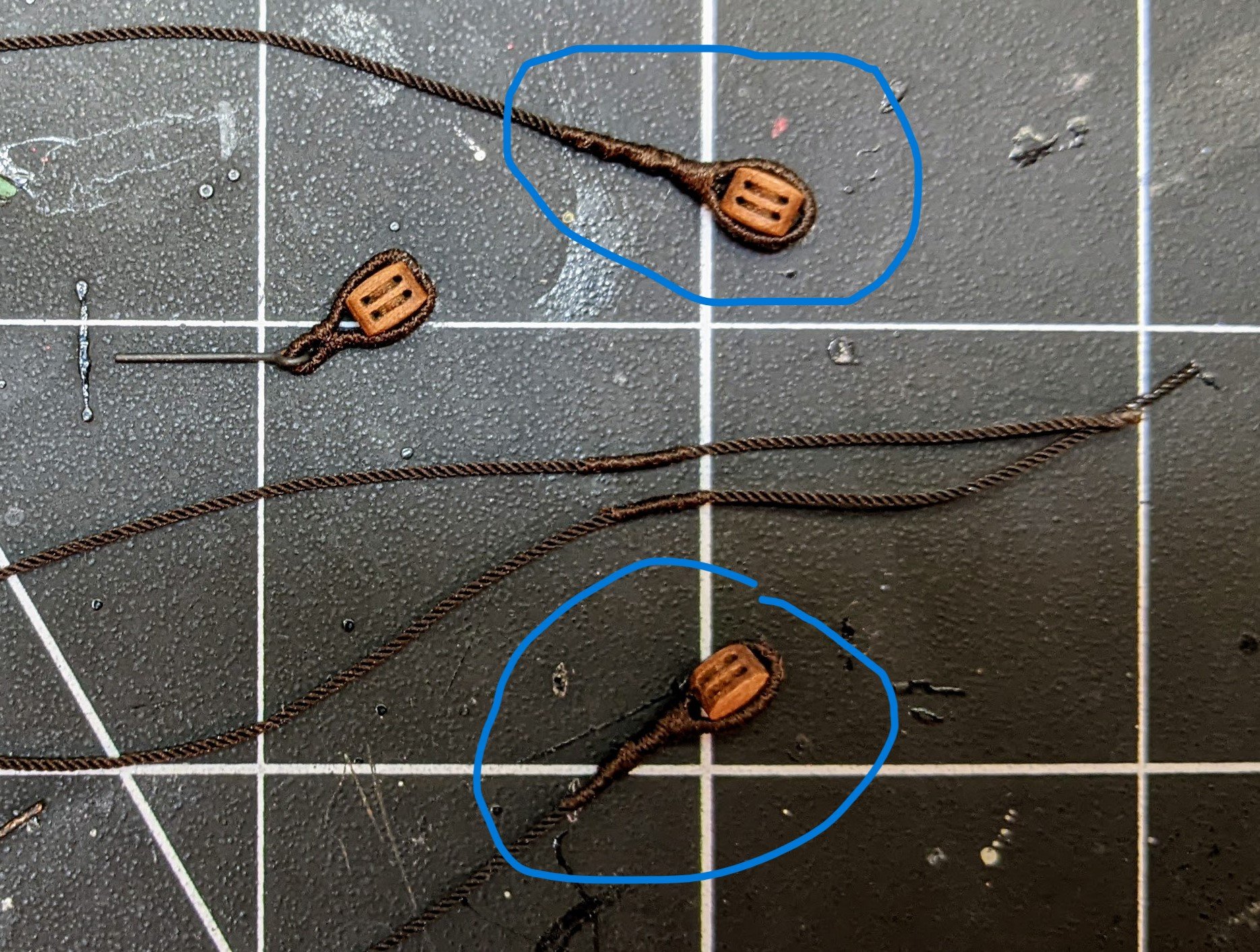
Looking really good, practice really does help with the rigging. If you would like a small suggestion, I believe the end would have been spliced into the rope and then the strop go over it. You can achieve this by doing a false splice (take a look at my alert log for some ideas), and then do the splice over top of it. I have also found some indications that many of these blocks would have been served all of the way round the block (though I have not really dug into this enough to be confident in this assertion). If you want to add that detail (completely up to you if you think it will add something), then the best way is to serve the length you need to get round the block leaving enough unserved end to do the false splice. Then you serve over the false splice bringing the whole thing together. See below for an example of what I mean:
-
Great job BE, I really like the modifications you are doing on this kit. Regarding the cable storage I had a similar question a while back (though it related to a Cruiser class vessel, I was considering building). There is no clear indication if it was shelves or walled off, if it extended down to the hold or not. I did ask the question and got a number of responses which though not completely satisfying may help you as you try to puzzle this one out. Post #28 has some analysis on the plans for the Argus which seem to show the cable tier as only going half way up the height of the deck so maybe the access was on the top?
- 332 replies
-
- 6
-

-
- Harpy
- Vanguard Models
- (and 1 more)
-
I am not sure I understand what you are saying. Can you elaborate a bit?
-
As we are nearing Christmas I thought I would give a final update before the new year. This will be a minor update as I don’t have a lot to show at the moment with Canada Post continuing to be on strike . That being said in the background I have continued to pick away at the research side of things. As can be seen in my previous post I have been attempting to draw up gun carriages. However, since that post my work has been complicated by the number of sometimes conflicting contemporary examples I have found. I am attempting to carefully work through them all to come to some conclusions. One thing I did discover (though it is not really surprising) is a primary source explicitly stating that the trucks and sometimes the brackets were modified in size to accommodate the differing heights of the ports on ships. This at least takes away the pressure of figuring out the exact dimensions of my carriages in the short term as I can safely build the ports as per the plans and then modify the heights of the carriages slightly if necessary. However, I have run into one oddity that I am wondering if anyone has any insight on. It is the question of the ends / steps of the brackets. Most contemporary examples I have found depict them as below with the steps / ends perpendicular to the centreline of the carriage (I say most as there are a few where it is unclear and though I have not run across an example which definitively does not folllow this convention, I have be no means looked at every available example out there): However, this seems a much more complicated way to construct them vs simply making the ends / steps perpendicular to the brackets themselves. Caruana’s redrawing of carriages seems to treat these ends/steps as perpendicular to the brackets themselves and it seemed odd to me that he would have done that for no reason. Does anyone have any insight into if this was just a drawing convention of the time or actual practice?
-
What I did is figure out which way it wants to twist and then twist the shroud a few times that way. That gives it tension which it wants to unwind from. It takes a bit of trial and error, but you can get them to line up right if you do that.
- 422 replies
-
- 3
-
-
- Vanguard Models
- Sphinx
- (and 1 more)
-
Google books has stalkartt 1781 here: https://books.google.ca/books/about/Naval_Architecture_Or_the_Rudiments_and.html?id=kdZLAAAAcAAJ&redir_esc=y
-
I have been doing some research on the construction of the knee of the head and I was wondering where exactly you got this particular plan from. The only stuff I could find on Constitution is in the modeler resources (https://ussconstitutionmuseum.org/discover-learn/modeler-resources/) and it didn't show the various pieces. You are correct in assuming that many of these ships likely used more pieces than is typically depicted on models. In my build log I go through the history of English construction of the knee of the head and list all the contemporary examples I could find. I would like to add Constitution to the list if you can point me in the direction of the original source for the above picture.
-
USS Constitution by mtbediz - 1:76
Thukydides replied to mtbediz's topic in - Build logs for subjects built 1751 - 1800
Nice work Mustafa, your are making good progress. -
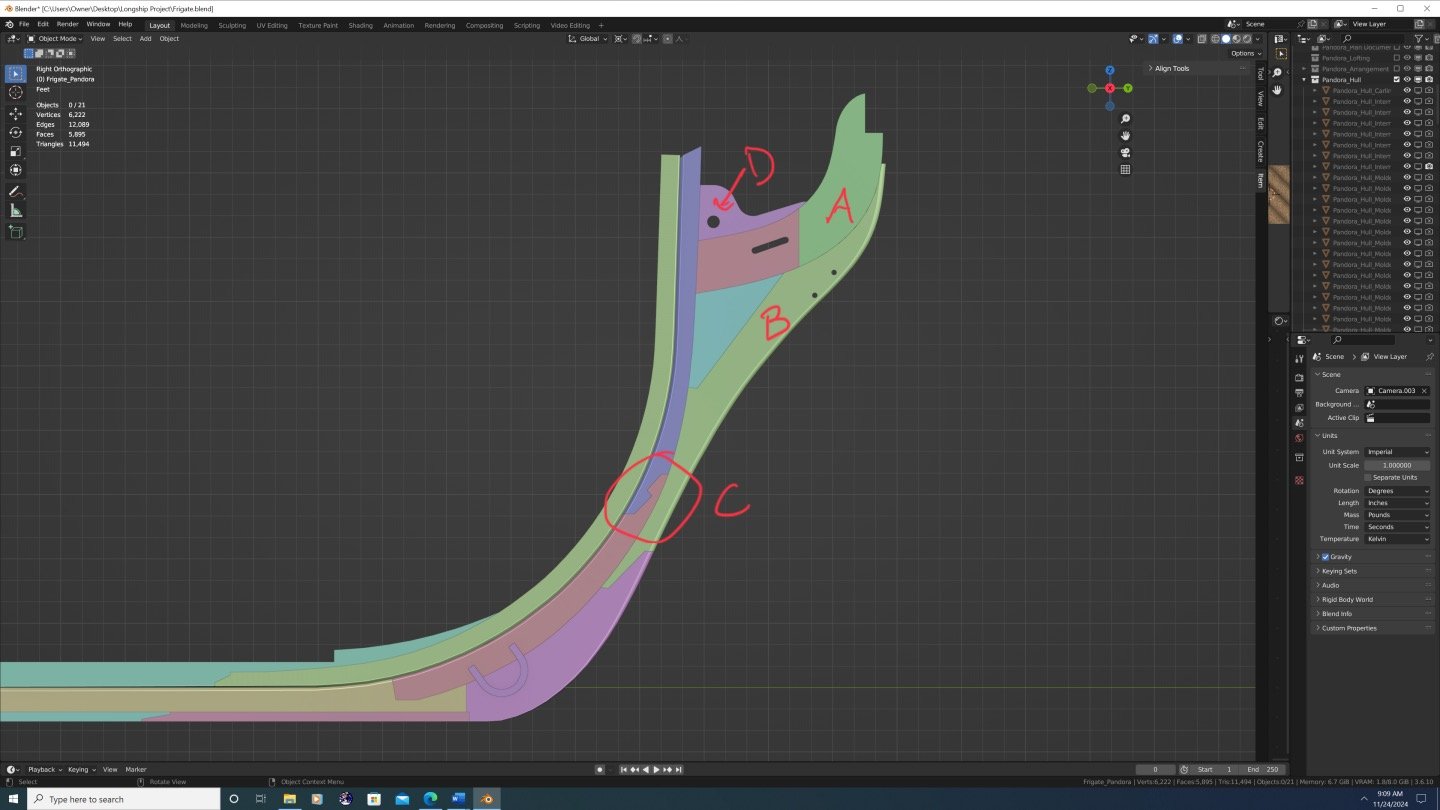
I will attempt to elaborate, but up front I should say that I think “incorrect” is a strong term. There are very few examples of how the knee of the head was constructed and lots of evidence that the shipwrights had broad latitude in the specific pieces that were used to construct them. This means that we can make our models consistent or not consistent with the examples that do exist, but there is no way to say definitively a particular arrangement is wrong. One could plausibly argue any given arrangement could plausibly have been used. I should also clarify that yes I am referring to the pieces that make up the knee of the head. The overall shape of the knee of the head is laid out in the draught and it appears to match the one held at the NMM. One small note here, I think your stem should probably be a simple scarf (same joint as you have for connecting the gripe to the main piece). If you look closely at the original draught this appears to be what they did and this is the joint I have seen on every stem I have looked at from the period. (see the bottom picture ‘C’) Also I just noticed that you have a scarf joint for the false keel. Again I am no expert, but I think that they were just diagonal connections as they were designed to come off easily if the ship ran aground. The gripe as you have shown it looks fine and matches most historical examples I have seen. The part I am less sure about is the pieces above the gripe (broadly the main piece, lacing and chock). With regard to why I question the Pandora book arrangement it basically comes down to two factors: The arrangement does not look like any of the historical examples I have found. If you have not already then please read through my two posts on the subject in my Perseus log. Every example I have found tends to use roughly parallel (or of a common curve) pieces which are more numerous than one might at first expect. It was much more economical to use more smaller pieces and there is lots of evidence to suggest that English shipwrights did this. A lessor point with regard to this is the Pandora book example is missing a cutwater (a small thin piece that ran along the leading edge of the knee of the head where it hit the water). There are also a number of practical issues / questions that I have regarding the arrangement that make me distrust the arrangement as described in the Pandora book: The shape of part A looks suspiciously like the shape laid out in the draught for the same area. The problem with this is that area on the draught is not laying out the shape of a piece of the knee of the head, it is just marking out where the figurehead would go. Part B is very thin at the top and is a very large complex shape. All examples I have seen for these pieces is they used simple shapes and I question if it makes structural sense to have such a thin piece at the front of it. It would make much more sense for the thin part of B to just be made part of A. My understanding of the standard (part D) is that it ran all the way up to the back of the figure (see the examples of the Swan class or Winchelsea models. The cheeks start out against the knee of the head, but at the tope they but against the upper piece of the standard (I can’t remember the name of that piece). This all being said it is your model and you are free to do what you want with it. As I said in the beginning this is not a question of right or wrong, rather consistent with historical examples or not. As I said previously, if you have any contemporary examples showing an arrangement similar to the Pandora books I would be happy to be proved wrong on this. The model is looking very nice. Good luck with it.
-
My understanding is that the garboard was just like any other plank, it was just wider. Steel does not mention anything in particular about them. Also most planking expansions I have seen, the garboard looks much like the other planks following the usual shift.
-
Yes Dacres was not the most handsome of men. The unibrow is quite impressive though I had not meant to imply that it was a Swan class vessel, I was just using them as an example. On reflection I have edited my internal version to remove the reference to the Swan class as it didn’t really add anything to the discussion in any case. Thanks for the suggestion.
-
I am pretty sure I found all of the contemporary examples that have been published online or in print. That being said if you find any others please let me know as I would like to include them in my research. One thing I will note with regard to the Pandora drawings in the McKay book. I have found no historical examples of the construction of the knee of the head that look like their depiction. I suspect what happened is they mistook the lines on the draught showing the location of the figure as marking off one of the joints. A more historically consistent (I say consistent instead of accurate as there are so few examples and so we don't really know the breadth of methods used) would be to do something similar to what I propose for Perseus (either with or without the scarphs) or to use an arrangement similar to that used in the swan class books sold by seawatch (there are lots of builds of the ship on the site you can see the arrangement).
-
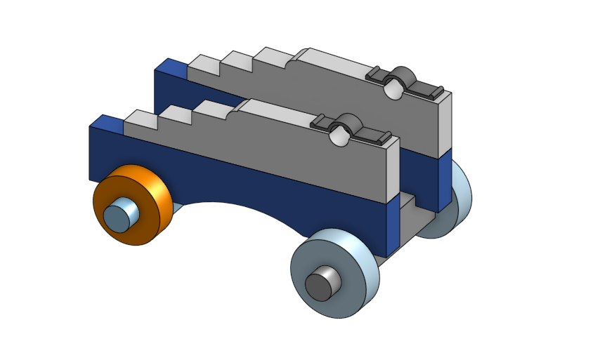
Log #12: First Draft of the Research Document Edit: I have removed the first draft as I have posted a revised version. Please see the first post for a link to the post containing the revised version. Thank you to everyone who has stopped by even though construction on the model hasn't started yet :). I have finalized the design and the first batch of materials have been ordered. Only issue is Canada Post decided to go on strike so it may be a while before I get the stuff. So in the meantime work has continued on designing things such as the carriages for the guns (see below for the current state of affairs on these) and ongoing research into aspects such as the figurehead and other details of Perseus' appearance. As I have hinted a number of times, in the background I have been working on a research document to keep track of my thoughts. There are two parts of this document which I suspect will be of most use to the community as a whole and Sphinx class builders in particular: Chapter 1, in which I review all of the plans and art available for the Sphinx class ships in detail. The appendices, which contain numerous relevant primary source documents I have compiled and transcribed. As the full document will likely not be completed until shortly before I complete the model I have decided to release it in parts. So attached to this post are chapters 1 and 2 along with the current version of the Appendices and Bibliography. For those who have been following along with my log, much of it may be familiar as I frequently copy sections from the document for my log posts. However, the document contains significantly more detail as well as extensive documentation of the sources used to justify the assertions I have made. If you have any questions, disagreements or find any typos then please feel free to get in contact with me. I would love to hear from you. Please note the following: This is very much a draft (I have only made one proofing pass through it) and so there may very well be errors. I will continue to be editing it in the background and at some point I will post revisions along with future chapters as they are completed. Because this is a draft, I have not yet gone through and adjusted the location of the figures to make sure they are spaced properly. As such I am aware that there are occasionally blank sections, but am not going to address these issues until I am much closer to the final version. This document is being released to benefit the modelling community so please feel free to use it to assist with your personal research and modelling endeavors. However, this represents a significant amount of work (I have been working on this for over a year at this point) so if you do use my material please make sure you credit the original author (either me or the other references as cited in the document).
-
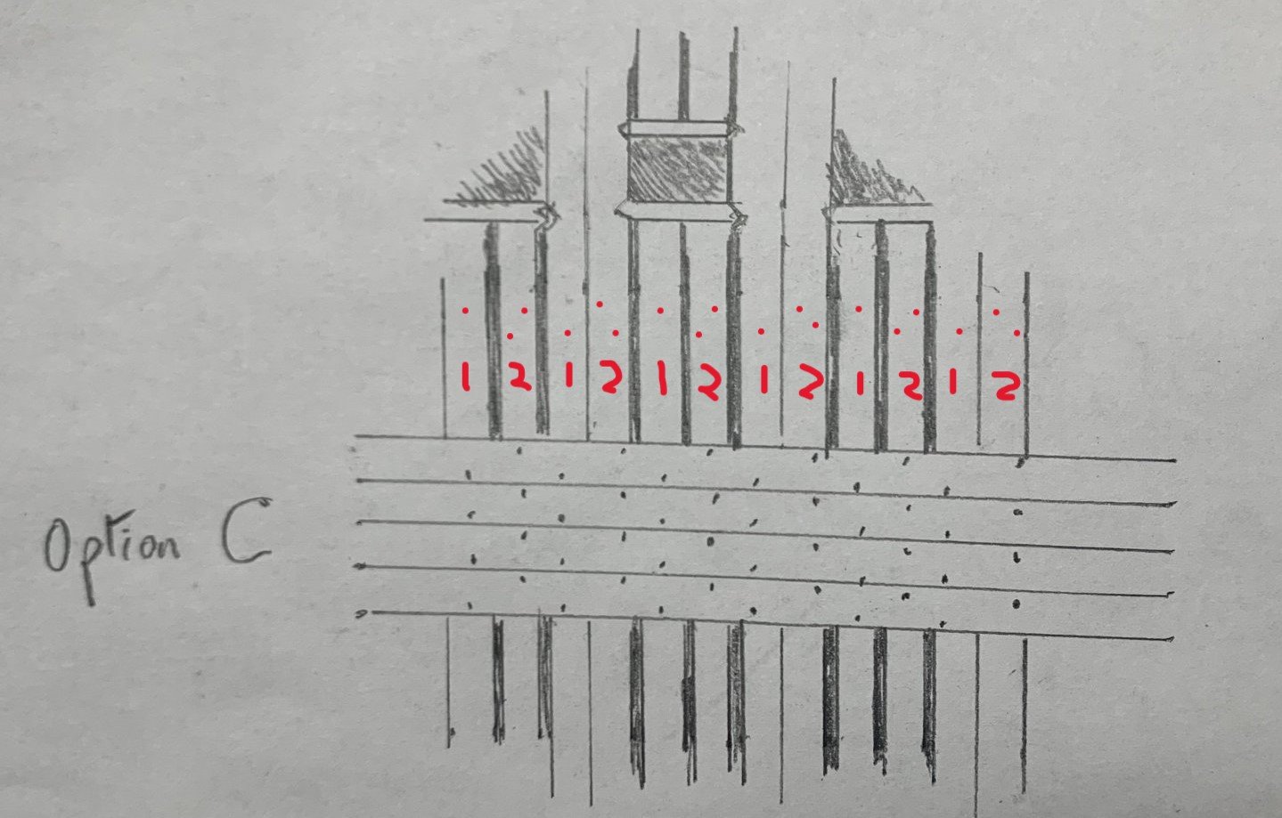
My interpretation of the statement was that every alternating timber gets a single treenail and the others double treenails. See below I added the number of treenails on each frame as well as a potential arrangement in red. That being said it is possible that the double futtocks were treated as one timber. I think an equally justifiable option would be to have two in each timber as per Ollivier. Ultimately up to you as I don't think there are clear answers here.
-
If I had to guess I would say that this is referring to the new steppings bracing system that came about around this time. I believe that Steel refers to to this elsewhere in the document. The key point in the quote above is not what they do currently, but what he says they used to do (2 treenails in one frame and 1 in the next).
-
This is what Ollivier had to say in 1737: Note: he previously notes that there were three ships being constructed in the dock at the time he was there, an 80, 70 and 60 guns respectively. I am not sure which two of these he is referring to in this quote.
-
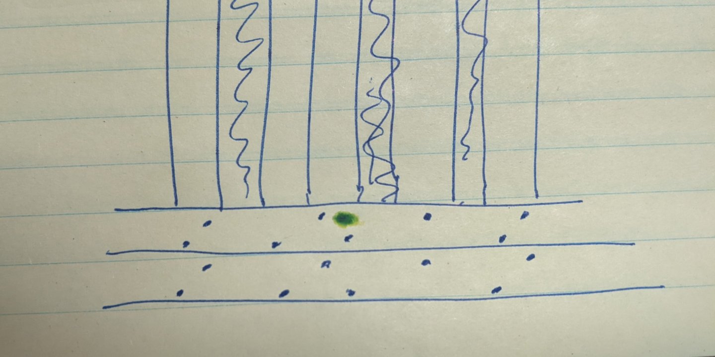
In Steel's naval architecture (1822, so a bit of a later period) there is a section near the end where he describes the process of making ships. https://archive.org/details/elementspractice00stee/page/167/mode/2up On page 37 of this section he says the following: What is interesting is what he has to say after talking about what is done currently. He says that alternating single and double treenails were used. Maybe something like this: I will take a look at my copy of Ollivier when I get home. That dates from 1737, but many of the techniques he describes changed very little over the course of the 18th century. He has a surprising amount of detail and maybe commented on the number of treenails used. I know he did mention the fact that the English used treenails much more than the French, but off the top of my head can't remember what else he said.
-
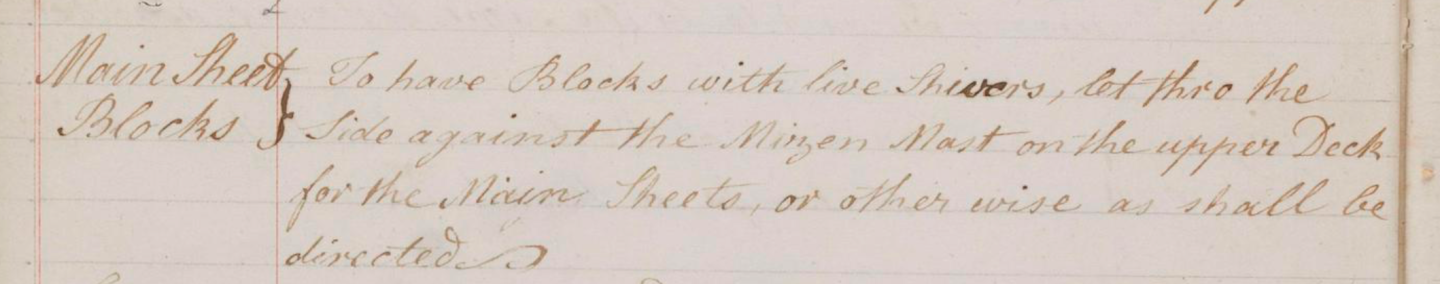
I am wondering if anyone is able to help me in interpreting the following lines in a contract. In particular I am confused as to what “live shivers mean.” I have included both the original text as well as my transcription. Mainsheet Blocks To have blocks with live shivers, let through the side against the mizzen mast on the upper deck for the mizzen sheets, or otherwise as shall be directed.
-
She is a really lovely model. If I wasn’t already committed to another project for the foreseeable future I would be sorely tempted by her.
- 76 replies
-
- 5
-
-
- Harpy
- Vanguard Models
- (and 1 more)