


allanyed
-
Posts
8,149 -
Joined
-
Last visited
Content Type
Profiles
Forums
Gallery
Events
Everything posted by allanyed
-
 Jason Anyone building a kit model should spend an hour or two studying your build log. You are showing what can be done to modify the plethora of unattractive items found in the majority of kit models into an expertly done piece of craftsmanship. Kudos Allan
 -
Your workmanship is fantastic! One thing that looks rather odd is that you show belaying pins even though they were not introduced until about 1745, more than fifty years after she burned in Cherbourg. Allan
- 69 replies
-
- 2
-

-
- soleil royal
- deagostini
- (and 1 more)
-
Hi Sonny, Have you checked out the tutorial on copper sheathing? https://thenrg.org/resources/Documents/articles/CopperSheathingaHull.pdf The plates would have had nail dents about 0.005" diameter at your scale, thus barely visible, rather than huge raised bumps. Keep in mind the plates should be overlapping about 1.5" (full scale) on both the short and long edges. Allan
-
Your workmanship looks really nice Jonathan. I am not very familiar with Mantua kits. Am I correct in assuming the kit called for belaying pins? The reason I asked is that they would not have been found the San Felipe or any other ship until about 1745 and then only on pin racks lashed to the shrouds for a number of years. There is an interesting article on this model and the ship, which may never have even existed. https://www.modelships.de/San_Felipe_1690_authenticity/San_Felipe_1690_authenticity.htm Allan
-
Dove by jlefever - 1:48 - Pinky Schooner
allanyed replied to jlefever's topic in - Build logs for subjects built 1851 - 1900
Jim, Your comments on the copper sheathing were music to my ears!!! For the life of me I cannot understand why there is not one kit maker that supplies accurate looking sheathing material, especially the representation of the nails, which would not even be visible on the smaller scales such as 1:72 or 1:98 You were kind to use the word overstated. I was thinking something a bit more intense. Allan -
Welcome to the fray John! You mentioned you were a kid in the 70's so it is super nice to see a "youngster" join the group. We love the scenery in your part of the country. Made quite a few visits there when our youngest was living out there with his brood and attached to the Stryker brigade at JBLM. Allan
-
Copper plates
allanyed replied to Barbara's topic in Building, Framing, Planking and plating a ships hull and deck
Thanks for posting this tutorial. These are far more realistic than anything seen from any kit on the build logs here a MSW. He does mention the missing nails inside the edges, but states that the plates sit side by side which was never the practice as they overlapped. Kit makers would be better served to supply the tape and pounce wheel if the wheel pins are spaced properly and the correct diameter for the scale of the kit rather than the dross most currently supply. One other note, the tutorial mentions rivets. Rivets were not used, but rather 1/4" nails with 1/2" flat heads. Allan -
Pay attention to the axles. In the photos on the website they are out of round. You may want to consider replacing those parts if yours come in with the odd shape. To make your own is easy and rounding the axles is quick. I have a few home made cutters sized for various diameters. Pictures worth a 1000 words, etc, etc. below Allan

-
Copper plates
allanyed replied to Barbara's topic in Building, Framing, Planking and plating a ships hull and deck
Hi Barb, Does your kit come with copper sheathing material or are you thinking of adding on your own? From photos of the Model Shipways' Pride of Baltimore models they appear to have a green (oxidized copper) painted bottom which is more realistic looking than the vast majority of the copper sheathed models seen here at MSW and elsewhere. Allan -
Soleil Royal 1/72 - Artesania Latina Ref.22904
allanyed replied to modeller_masa's topic in Wood ship model kits
For $900 I would expect a little reality from the kit producer. The photos show belaying pins. Belaying pins were not used on French (or English) warships in the 17th century, and if they had been they would not be the size of bowling pins. The gratings look nothing like gratings on a ship of any era. The sided and moulded dimensions of the frames on the ship's boats are huge compared to what they would have been. There are more items, but in the end you are the one to decide if these kinds of things are important, or maybe consider doing a kit bashing to correct them. Allan -
Thanks for information Gary, I did not see these on their website but found it now. Good to know for the future although 😀
-
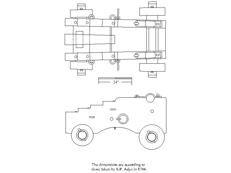
Jim Kudos to you for doing this research. I would not trust everything from Caldercraft without confirming with some independent research as you are doing. If you are looking to make your own carriages to actual dimensions of the time, Caruana's History of English Sea Ordnance, Vol. 2 is a great source. There is a detailed drawing of a 24 pounder from 1760 on page 377 and another from 1791 on page 378. Looking at pictures of the Vanguard 24 pounder carriage, they look similar to that of 1760. The Caruana drawing has the carriage at exactly 6 feet long which would be 1.125" long at 1:64 scale. Unfortunately the Vanguard is at a different scale, 1:72 so much too short if it is to scale and if your scale is 1:64. I agree with Gary that the Armstrong pattern is appropriate for the time Agamemnon was launched so the 1760 pattern would apply. The below is a mirror image tracing of the drawing found in History of English Sea Ordnance. If you need a pdf of this, PM me and let me know what scale you need and I can email a copy to you. Allan
-
Thanks Eck! I thought the kit might be the problem and your post confirmed the designers of this kit, at least, have no idea how planking was actually done or maybe don't think it is important. You mention copper bottoming covering the planking. Unfortunately most kit supplied plating is as bad as the planking instructions. With one or two exceptions of kit makers, the plating looks like that in the photos above in that they have huge pimples that look like giant rivets instead of tiny dents from the 1/4" nails that were used. At 1:98 or even 1:64, it is probably better to use copper tape with no markings at all. Then once the plates are applied and overlapped like shingles, as was actually done, it is not that difficult to use a pin to push in tiny dents which is what the nailing would look like. At 1:98 or similar scale, it may be better not to try to show the nail pattern as the dents would only be about 0.005" diameter 😀 I look forward to your progress here and on Victory. If you do not already have one, be sure to get a copy of Longridge's Anatomy of Nelson's Ships when you start the Victory model. It will help your build immensely. Allan
-
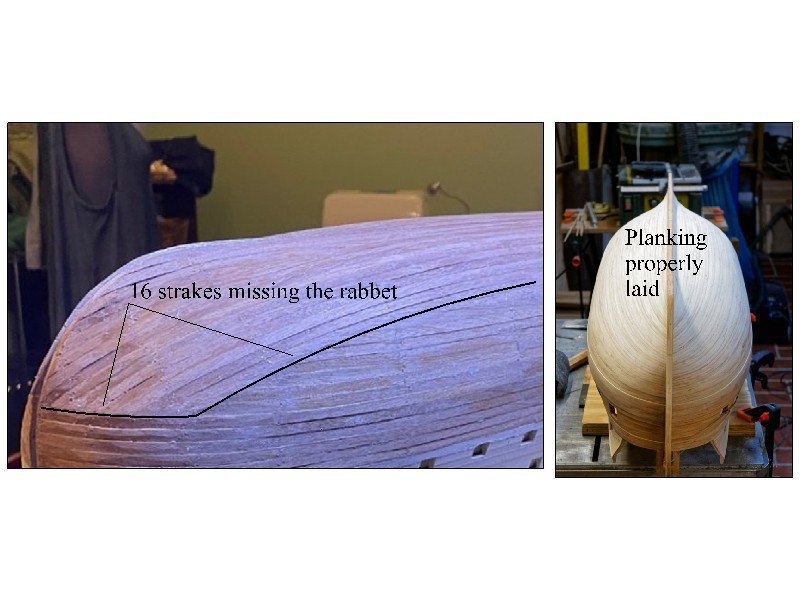
Eck Your construction looks very clean and precise. One question I have had for a long time that maybe you or some other member can answer. In looking at build logs here over the past years I have gotten more and more curious about the style of the planking pattern. Why are so many kit models planked this way instead of the way a ship was actually planked? Are these erroneous instructions from the kit makers? I understand the double planking allows for correcting errors in fairing the hull, but why the unrealistic pattern? Other than the occasional drop strake, all the strakes should end at the rabbet. The pic below shows the area to which I am referring. Thanks Allan
-
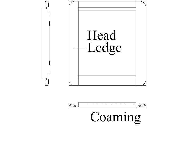
Hi Siggi, Your build log has been a true joy to follow. I do have a question regarding the joinery of the head ledges and coamings. I was taught that they overlap rather than connect at a 45 degree angle. Do you or does anyone here know if both methods were NORMALLY used or just the overlap method where the head ledge rests on the coaming. The 45 degree angle is surely easier than the complexity of the overlap.
-
74 is not so bad, they had 120 when launched and carried 10 guns versus 6. Allan
-
Thanks Chimp and Don The reason I asked about this was that there were only 74 people on board for her second voyage in 1831 which carried Darwin but there looks to be nearly 200 hammocks in the bulwarks so I could not reconcile the two things. Thanks again Allan
-
Your build is quite nice Chimp! Do you know if the OcCre kit represents her as she looked when launched in 1820 or for the cruise with Darwin in 1831? Thanks! Allan
-
Thanks Tom Allan
-
Hounds and Cheeks for Endeavour finished in 1761
allanyed replied to DaveBaxt's topic in Masting, rigging and sails
DaVE, Lees describes this for the lower masts on page 2 and for top masts on page 4. It is my understanding from looking at his drawings that the trestle trees sit on the cheeks, hounds, and bibs as they all end in the same place. Hopefully a member more knowledgeable can confirm or correct this. I am not sure if any of the contemporary drawings would be right for Endeavour, but you can find a lot of mast and spar drawings on the RMG site. Some may be more appropriate than others. There are a number of high res contemporary drawings of spars and masts on the Wiki Commons site as well. One example can be seen below for a 74 of 1780 which may not be appropriate for a smaller vessel like Endeavour. There is a high res drawing of lower mast for a 28 on the Wiki site as well. Allan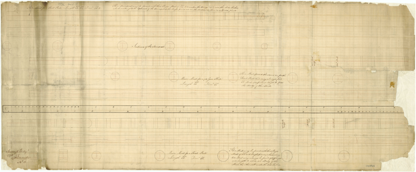
-
Hairy/fuzzy rigging thread
allanyed replied to The Gimps Chimp's topic in Masting, rigging and sails
According to the American Bee Journal, bees wax has a pH of 7 thus neutral (https://americanbeejournal.com/beeswax/#:~:text=As beeswax is the primary,7) suits the need perfectly) so not a bad thing to use, but it will only lay down the fuzzies to a limited extent and not get rid of it. You are better off to make your own rope as mentioned above or buy from the various rope suppliers mentioned here at MSW. Allan -
I suspect the name would have been removed as well as the RN did not allow names on the sterns except between about 1780 and 1790. Allan
-
Kevin, Did you mean the contract versus the build log? 😀 I found drawings of Ulysses 1779 on the RMG site including lines and body plan as well as an inboard profile but note that the writing on the plans themselves only name Roebuck. In the description from RMG it states that the drawings are appropriate for 16 additional ships of the Roebuck class including Janus and Ulysses. For the deck plans, I suspect the Janus plans will be very close if not identical for all the ships. https://www.rmg.co.uk/collections/objects/search/ Ulysses 1779 Note that the Hahn drawings have differences with the RMG drawings. An example of the upper deck is below. Some might not worry about these minor discrepancies but your build logs show you are meticulous, which I applaud. Allan
-
Kevin, If you are going to build Janus 1778 at 1:48, am I correct in assuming you have the four sheets of contemporary plans for her from RMG? Maybe they would be at least a supplement if not a replacement for the Hahn plans which may or may not be as accurate when compared to the contemporary plans. https://www.rmg.co.uk/collections/search/ Janus 1778 . For scantlings she is probably very close to the scantlings in the 1745 Establishment taking into account the 1750 Establishment alterations and or Shipbuilders Repository 1788 but you can get also get a copy of the 23 page Roebuck contract which will likely be even more accurate for the Roebuck class ships including Janus. https://www.rmg.co.uk/collections/objects/rmgc-object-459410 I think you are quite fortunate. I would absolutely love to have an artifact from a 17th or 18th century ship for which there are contemporary plans available for a project. Allan
-
I love learning these kinds of things that come out of a post Druxey. Gratias tibi. Allan

