allanyed
-
Posts
8,149 -
Joined
-
Last visited
Content Type
Profiles
Forums
Gallery
Events
Everything posted by allanyed
-
 Ciao Matiz Thanks again for continuing to share, it is a pleasure to follow your build. buon Natale!!! Allan
 -
3D Printed Plank Cutter
allanyed replied to spill50's topic in Modeling tools and Workshop Equipment
Your cutter is very impressive! I think if you had an inventory of cannon barrel STL drawings covering 1600 through about 1825 and 3 pounders to 32 pounders you could be kept quite busy with your hobby of 3D printing. Actually one or two drawings for each period would probably work as I know you can scale them up or down for various scales and sizes. I have been using 3D printed barrels on two projects and the detail is as detailed as the drawings. Based on some of the build logs here at MSW I am flabbergasted some kits still provide cannon that are more imaginative than realistic in shape and scale size, so your audience could include both kit and scratchers. Then again, it is no longer a hobby if you go into production and maybe not so much fun. Allan -
Mondfeld v Lees Masting and rigging
allanyed replied to DaveBaxt's topic in Masting, rigging and sails
Dave, Just remember that the Vadas spread sheet is completely wrong for the period between 1670 through 1710 and should not be used if your vessel falls into that time frame. Allan -
Dave, Interesting point. I do not recall ever hearing of or seeing a tarred anchor line on contemporary models, but....... Remember that the anchor cable did not go around the capstans, but rather the messenger did. Allan
-
Juraj The main boom crotch usually stepped in a matching hole in the taffrail when the vessel was not underway but removed otherwise as it would of course interfere with movement of the boom when underway. It was secured by setting up the sheet hard and with crotch tackles. As you plan to put on sails as if she were underway, the crotches would be removed and stowed. I cannot find anything on whether they were stowed below deck or secured in someway on deck when not in use. If you choose to have the crotches in place, there is a detailed explanation of how to rig main, fore, and jumbo boom crotches in Chappelle's American Fishing Schooners 1825-1935 p431 Allan
-
Dave, It may be the photo but the bore looks oversized and off center. The bore of a 3 pounder at 1:64 should be about 0.045". The website in Kirby's post is a good one and easy to use. The dimensions match those in other sources including Caruana et al. Allan
-
Chain Plates Gor 16th Century Spanish Galleons
allanyed replied to Bill Jackson's topic in Masting, rigging and sails
Glad to see you are back and feeling well!!!! Allan -
Hi Joseph, I agree with Bruce, it would be polite behavior if you would first post a hello and little something on the new member forum. I also agree you have a good question and I too am anxious to see if there is a contemporary answer to your question. In the meantime, welcome to MSW!! Allan
-
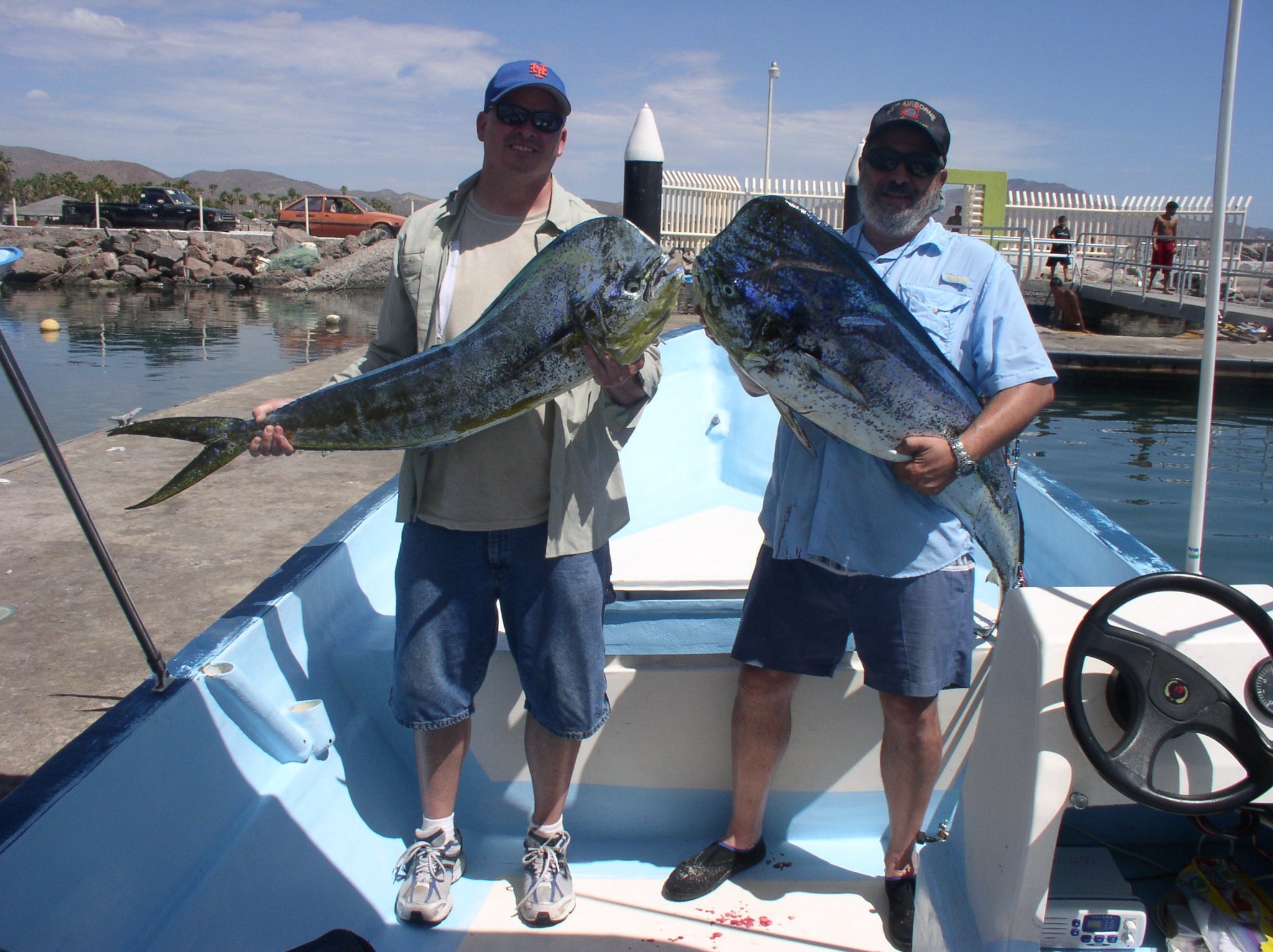
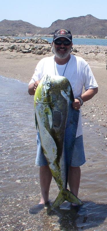
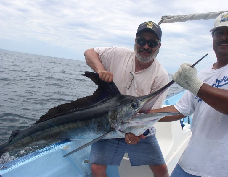
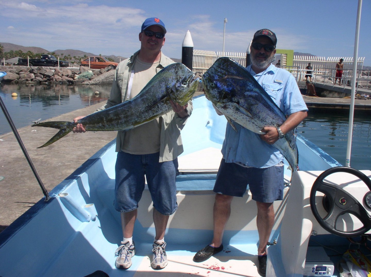
Even in Mexico there are daily limits on most species to avoid overfishing. For the dorado it is two per person which we share with the panga captain and local restaurants as we can only carry so much in coolers on planes back to the US. Allan
-
Welcome to MSW Jay, As this was your first post it would be nice if you posted a little introduction on the new members page. Questioning plans from most kits is a good idea, and based on the drawings you posted, well founded. What ship and year? Can you share where these plans come from? The reason I ask is that there appear several errors in the drawings. There looks to be pairs of double blocks for the training tackle and running out tackle which is not correct for a Bromefield 32 pounder. For 32 pounders there would be a single and double. For lesser calibers there would be two singles. (Caruana The History of English Ordnance p386) The breech did not attach to the ring as shown. This appears to be a Bromefield gun so for that era, the breeching line would secure to the ring with a half hitch and then the tail would be seized to the standing part. (Caruana The History of English Ordnance p.384) I have never seen bolts in the knees but I don't know if this was actually done at times. Maybe someone else here at MSW can verify if they only secured into the bulwarks or at times went into the knees. Goodwin provides a chart for the carriages of various sizes of ringbolts and eyebolts on page 217 of The Construction and Fitting of the English Ship of War. For your 32 pounder: For a LONG 32 pounder he gives the following RING BOLT EYEBOLTS Bolt diameter Ring internal diameter Bolt diameter Ring internal diameter 1.5" 5.75" 1.25" 2.75" I cannot find dimensions for the breech rope rings but scaling from 2.5" circumference running tackle rope to 7" circumference breeching should get you very close. Same for your port tackle and muzzle rope. You can size by ratio based on the line sizes. Keep in mind that the smaller guns on your model had different size rings and bolts. Allan
-
Dave, If you have not yet found this, https://books.google.com/books?id=aztFAAAAYAAJ&printsec=frontcover&source=gbs_ge_summary_r&cad=0#v=onepage&q&f=false Just remember it is from 1812 so may not always fit for 18th century. Steel's Elements and Practice of Rigging (1794) is another free source for very late 18th and early 19th century, https://maritime.org/doc/steel/ Allan
-
Thanks Pat!!! Yes I do have this and for the early 19th century I have found both Steel and the Vade Mecum to be extremely useful. Allan
-
Dave, The bore for a four pounder Armstrong cannon of 1760 was 3.204" so the breeching rope was 3". By about 1770 four pounders were all 5'6" to 6' long. Their predecessor, the minion could be as much as 7 feet long. I found similar information on the running tackle that you posted in Lavery's Arming and Fitting which indicates the running tackle is 2" except for the 24 pounders and larger which was 2.5" Allan
-
Mick, I am not familiar with the area you mention as I live in Florida. Sorry to go off topic, but as you are a fisherman I thought you would appreciate the following. We had a 25 foot sport fisherman but sold it after having it for 10 years and took up golf. I still try to get out on the water for fishing four or five times a year though and as a former seafarer in the merchant marine, I think I will always have a love of the sea. Still like to gather with friends in Loreto, Mexico for a week of fishing the Sea of Cortez every year or two. Pictures from one of the best trips to Mexico follows. Two of us had 124 dorado (mahi mahi) over 30 pounds and four striped marlin (all released.) Allan
-
Dave, What were the gun sizes? If you have the weight of shot and barrel length, that may be enough information to find rope sizes, more so than the rate of the ship. Look up the gun sizes of 5th and 6th rate ships around the time of Endeavour and if they are the same as what Endeavour carried, you are in luck. Are you looking for the breeching, running out, and/or training tackle? There is also the muzzle lashing but I cannot recall ever seeing these on a model. Taking a look in Caruana's History of British Sea Ordnance Volume II, he gives information on diameter and length of the breeching rope for various calibers and barrel lengths, but I could not find the running out or training tackle sizes. The muzzle lashings were 2" diameter for all sizes according to Caruana. Lees is always a good source on most any type of rigging within the confines of time he covers. Anderson is good between 1600 and 1720 so not appropriate for Endeavour anyway. Allan
-
Welcome to MSW Art, Contact the Chesapeake Bay Maritime Museum boatyard in St. Michaels, Maryland and ask them about this. They were very helpful to me and even allowed me to take 2 foot long piece of an original keel from a skipjack they were restoring on one of my visits to their facility. I used this wood to cut into planks on my last skipjack model. https://cbmm.org/exhibitions/working-shipyard/ The following lists individual skipjacks and you can do a search of these then contact the owners directly. http://lastskipjacks.com/list.html Allan
-
They look to have very competitive prices for Foredom products. Are there good reasons to go with their 1/3HP rather than the 1/6HP for our ship model drilling and carving needs? My old Dremel flex unit is still working, but I am not sure how much longer it will last. At least that is what I keep telling myself in order to justify the expenditure for a Foredom unit. TIA Allan
-
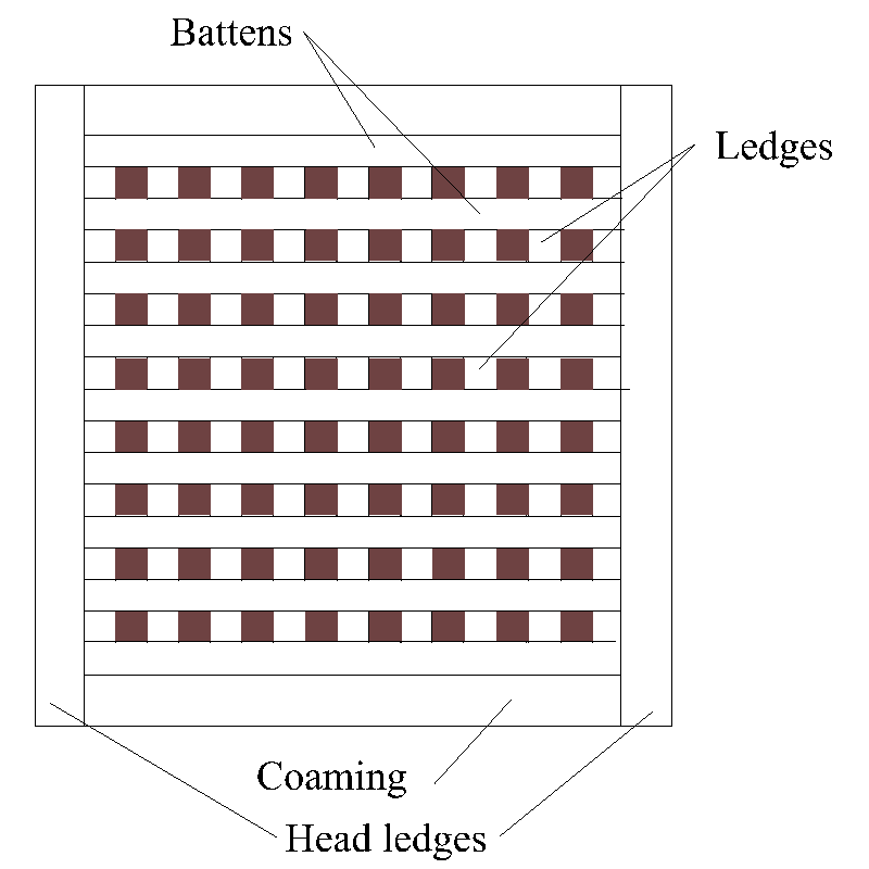
It is always a learning process Mick. Lord knows I never run out of new information (because of my making mistakes) after forty five years of scratch building in this hobby. Regarding the battens and ledges of the gratings, the below is easier than words. I admire you taking on scratch building. For your next build, if you continue with scratching, there are about 800 sets of high resolution plans held by RMG available for free along with a couple thousand low res available on the Wiki Commons website. There are of course thousands more available from RMG in low res for free and high res for a price. I look forward to your next build log! Aside ...... are you an aficionado of Thorndike's Doctor Syn book series? If you are, would you recommend them to a prospective Romney Marsh series reader? Allan
-
Just checked in to your build log and find your model to be one of the best executions of a Bounty kit here at MSW. Your workmanship is extremely nice to see. One thing to keep in mind for the gratings when you get to them on the upper deck, the ledges run athwartships and the the battens run fore and aft, not the opposite way as they appear to be on your lower deck. The contemporary drawings and other images of the Bounty on the RMG Collections site may be helpful if you have not already researched them. https://www.rmg.co.uk/collections/objects/search/Bounty Looking forward to your next posting and photos! Allan
-
Hi Syn, What they seem to show are ties, not jeers. It is hard to tell from the drawing but it looks like they may actually be a combination of ties and jeers on the same line which I don't think was ever used. Ties were no longer used on small ships by about 1640 and 1660 on large ships. Both Franklin and Lees concur on this approximate time line. I realize it is not your doing, but rather the kit plans, as I see a several other things that are not correct. For example, there are what appear to be holes in the bitt cross pieces as if there were supposed to be belaying pins. The problem is belaying pins were not used on Mordaunt, or any British ship in the 17th century for that matter. And, when they came into use on cross pieces in the 18th century, they were not in double rows. Another example are the gratings. There should not be open holes on the ends, and the battens should be running fore and aft, not the ledges. Again, I assume this is likely poor research on the part of the kit maker. For future, it is always a good idea to research everything with most kits the same as if it were a scratch build. If the rigging situation is still unclear, my apologies. Let me know and I will try to take a little time to do a sketch as I don't think it is a good idea to post copies of the drawings from the books as they are under copyright protection. Allan
-
Thank you very much for the smile you gave to another person with their fair share of senile moments (that person being me😀) Glad the other information may be of help. Allan
-
HMS Granado 1742 Kit - CAF Model - 1:48 Scale
allanyed replied to cafmodel's topic in Wood ship model kits
Your model really does look super Tom. One question, hope you don't mind. What diameter are the treenails for the deck planks? I believe that at your scale they would normally be between 0.015" and 0.02" diameter (3/4"-1" full size). Thanks Allan -
Hi Jim, That drawing looks like Agamemnon 1781. Can you share how did you came to find this is from 1876? The reason I ask is that the British were building ironclads by 1876 and the vessel in the plans is surely 18th century, not late 19th century. Your signature has you building the Caldercraft Agamemnon which is the 1781vessel so a little confusing (or maybe a typo 😃) Mike may be correct, but assuming this is Agamemnon 1781 the arrows might not be the top and bottom of the wales. The bottom arrow looks to be pointing at the wales but the top arrow is pointing at what may be the black strake, which is not part of the wales as it is not as thick as the wales. The main wales of a 64 like Agamemnon in 1781 were 7" thick and later in the century went to 8" thick. The main wales on a 64 were 4' 2" broad (0.78125" at 1:64) The strake on top of the wales (which I believe is also known as the black strake) was 6.5" thick and 16" (0.25") broad. The planking above this strake was 4" thick. These figures are from both The Shipbuilder's Repository 1788 and Steel's Elements and of Naval Architecture 1805. As an FYI, the Establishments up to 1750 gave a thickness of 7" for a 60 (there are no 64's in the Establishment scantlings). The strake above the main wales in the Establishments was 5.5" thick. Allan
-
Warm welcome to you!! Glad to hear the sea takes precedence over air!! Allan
-
Syn I found a fourth rate Mordaunt in the 17th century, (1681) but no Mordaunt from the 18th century. It probably does not matter too much as the rigging for the jeers was pretty much the same from 1670 to 1811 depending on the rating of the ship. Can you post a photo or two of what you have found so far? If it is indeed from 1681 Richard Endsor has fantastic plans/ drawings of her in The Master Shipwright's Secrets that you would benefit from having to achieve accuracy in your model. In the meantime, based on information from Lees' Masting and Rigging English Ships of War and Anderson's Rigging of Ships in the Days of the Spritsail Topmast (1600-1720) I there would be a double jeers for the lower yard (both main and fore). There are very clear drawings of the upper part of the jeer rigging on pages 64 and 65 in Lees' book. In general each standing part was hitched or seized to the yard. Each of the two running parts rove between upper and lower blocks on the yard and sling in the tops then went down to the bitts. The port line went through the inboard sheave on the port bitt and belayed to the cross piece. The starboard line went through the inboard sheave on the starboard bitt and then belayed to the cross piece. Neither line went through two sheaves. Other lines ran through the other sheave holes. Belaying pins were not used at the time of Mordaunt. In case you have not already seen these photos, there is a model of Mordaunt 1681 at RMG that you can see in the collection section. https://www.rmg.co.uk/collections/objects/rmgc-object-65965 This is a admiralty style, not rigged, but may be of some help none-the-less. Allan