allanyed
-
Posts
8,149 -
Joined
-
Last visited
Content Type
Profiles
Forums
Gallery
Events
Everything posted by allanyed
-
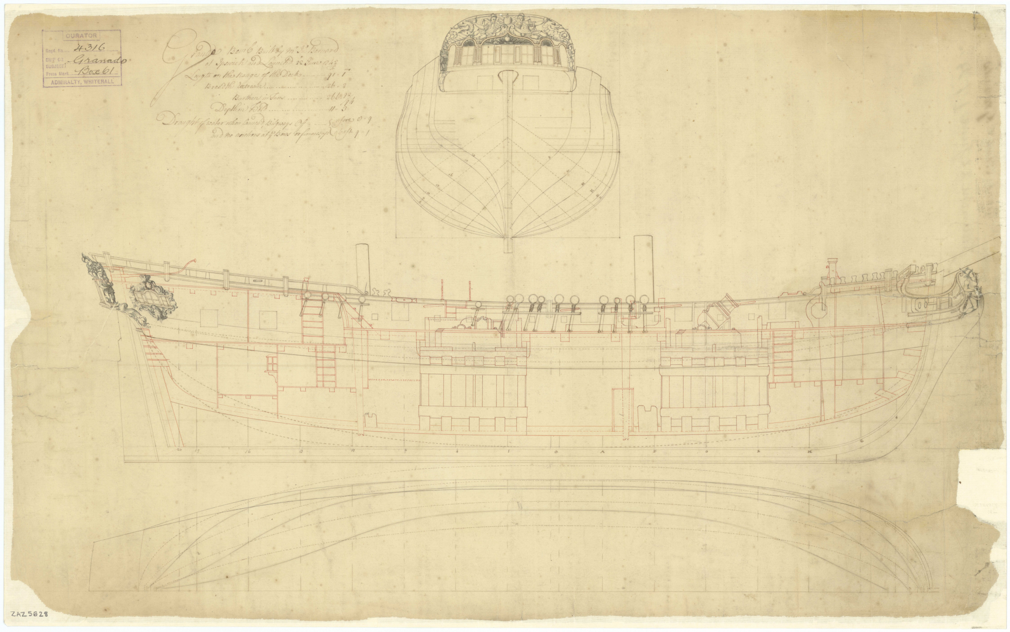
 Brian The actual timber heads could very well be extensions of top timbers so it would be more realistic for the holes in the cap rail to be enlarged. A sharp chisel should do the job very nicely. Not sure a file would fit in the holes. Either way, I doubt anyone will be able to tell if the fit is really good. Note the kit has five timberheads between the aft most and middle swivel gun posts, port and starboard on the forecastle. The contemporary drawing shows six. You can study the drawing to see if there are any other differences between the kit and the original drawing of the actual ship. The contemporary drawing is below, but if it is not clear you can download the high res drawing (43mb) found on the Wiki Commons site for free. The drawing is on the first page. There is another drawing of Comet, Terror, Granado, et al from 1741 that shows no timber heads on the forecastle. It is at https://www.rmg.co.uk/collections/search/Granado 1742 but is low resolution. Allan
-
This is what it’s like to be a newbie
allanyed replied to Laggard's topic in Masting, rigging and sails
Nipper Welcome to MSW. Reading your post, a word of warning. You may wind up getting the total scratch building bug like many of us which brings a whole new world of potential subjects to your doorstep. 🤪 Again, welcome to the fray here at MSW (Please post an intro on the new members forum here at MSW.) Allan -
Michel The insert is indeed a board. I used the same material that I used for the frame so the thickness matched. It does not have to be a perfect fit. A clearance all around of 2mm or so is fine. The purpose is to prevent the silkspan from sagging to the floor when it is first wetted for shrinking or when painted as it will sag again then tighten again. There are some alternative ideas on You Tube as well although I prefer the painting methods in the booklet. NB: - Use good quality tubed artist acrylic paints in any case.
-
I have never been thrilled with the look of treenails at scales smaller than 1:48, but after seeing your work, I am reconsidering this as my current project is 1:64. Sorry if I missed it if you already mentioned it, but what material are you using for the treenails? I cannot think of any wood that goes through the smallest holes in the Byrnes plate without problems other than bamboo, at least based on my own experience. Allan
-
Michel, OFF white is probably appropriate. Mix a LITTLE burnt umber and/or yellow with some white and keep track of the proportions as you mix until you find the color you want. There are no color photos of vessels from that far back so no one knows the color other than descriptions words that some may have found and can share with you. The seams just need to be slightly darker than the color of the sail. Look at the build log for the Boothbay schooner under scratch builds and you will see one way of making these, but it generally follows the book by David Antscherl. The sail making is near the bottom of the page. As a side note, according to the USS Constitution Museum, flax was used to make sails in the US Navy until well into the 19th century so that may help you research the color a little bit. Allan
-
Nice work Will, Have you tried making the chains and putting them in place with the deadeyes, then, blacken them with watered down LoS. Quick rinse with water afterwards and no residue flaking off. If you look at Ed Tosti's Naiad log build and/or the Young America build log, he goes into this method in some good detail. Allan
-
Welcome to MSW Bob! You have attached your post to a 7 1/2 year old string here. You may want to do two things. First, a common courtesy would be to introduce yourself on the New Member forum. Second, start a new post in the appropriate forum with your questions and post some photos to give a better understanding. Again, welcome to MSW!! Allan
-
When I ordered the book on Thursday Amazon claimed delivery would be tomorrow, Monday. It was not as they claimed!!! Darn!!! (The book showed up a day early and now my day is shot as I dig into the book. ) Happy happy Allan
-
Michel Absolutely get the booklet that Druxey mentions. It goes into all the details including proper paints to use to get the color you want. Added to the booklet which I used with success, I did change the method of making the seams to using paint markers that were slightly darker than the sail color once it was painted. You can trim the tip of the marker to the width of the seam which would be about 2" real world. I used Liquitex but there are others. Using the marker and a straight edge yielded great results, better for me personally than using a brush in my shaky hands. https://www.dickblick.com/products/liquitex-professional-paint-markers/ scroll down to a wide selection of colors. I am sure there are many more suppliers in Canada in addition to this one here in the States but this site will give you an idea of what is available if you care to try this method. Allan
-
Regardless of the wood species, as there are lines of what looks to be a body plan, you can make the hull from segments based on these lines. Alternatively you can go with a solid block as you mention and make card stock pieces from the body plan lines to check your fairing of the hull from stem to transom. Basswood may be OK as it is good for carving, but I find it prone to denting and scratching as it is soft compared to other readily available species, including poplar or maple which you can get at any local lumber supplier. Do you have a CAD program? Allan
-
This is what it’s like to be a newbie
allanyed replied to Laggard's topic in Masting, rigging and sails
Laggard, You are not alone . Anyone of us who cares about the quality of our own models are our own harshest critics. That is a good thing!! Allan -
I was looking forward to everyone's reviews, but could not wait so I just ordered a copy on Amazon and it gives a delivery for Monday. Glad Jeff B. did his thing back in '94. Sure saved me a lot of gasoline not having to make so many trips to stores! I know he has his detractors but I wish I had been smart enough to think up the concept and take the plunge to start a business in my garage like he did. Allan
-
Trafalgar, 216 years ago. Allan
-
Have you looked at the modern (1947) model at NMM? Do a search in their collections section for the Earl of Pembroke. Endeavour was originally the merchant collier Earl of Pembroke, built by Thomas Fishburn. There are six views including the one below that may help you. Note that there are no belaying pins on rails. There may have been some pins rails tied to the shrouds. Allan
-
Jamie, There are no secrets on the web. I was a CIA agent for years and researching is part of the craft........ (That is a big fat lie. it was the FBI,,, not!) I was a salesman for most of my career and spent a LOT of time researching to find and learn about potential clients and their products before ever contacting them. Research paid huge dividends just as research pays dividends (for me at least) in this hobby. Some prefer to just jump in and sink or swim, but whatever works for you, go for it. There are not that many so called "right ways" to do anything in our hobby. The end result is what counts as well as having fun in the process. Allan
-
IPA should work on removing the stem. It will take a good bit of alcohol with a swab or brush and you need to work briskly as it evaporates quickly. It will not stain the wood but if there is any residual glue on the wood it may show up. This should be sanded off anyway so no harm. Once removed, be sure to sand any residual glue from the stem and the center piece before gluing it back on. I agree with mark, do not remove the fillers, they need to be part of the fairing process. Allan
-
Jamie?? You are trying to edge set the planks which does not work. You have to either spile them or soak and pre-bend the plank around a form then heat it as shown in the tutorials here at MSW. You can try both methods to see which works best for you, but keep in mind you may have occasions where one works easily and the other does not, depending on the severity of the bend, the type of wood, etc. If you are stuck with strip wood from the kit, you will be relegated to moisture and heat to side bend around a form before putting on the hull as spiling requires wider stock so you can cut the plank to the proper curve. I noticed you have not marked out the bulkheads with the width of the plank at each bulkhead so you can be sure your planks are properly tapered. This will really help you get fair lines of planking. Cheers Allan
-
I found a bunch of solutions on the 'net from heat to alcohol to vinegar. My preference has usually been alcohol. The problem is getting it to the glue. If you have a large area and there is glue far from the seam, it will be difficult to get the liquid to those areas. Pictures may help get a lot of responses from members that also have to go through this. Cheers Allan
-
Today in 1805, the battle at Trafalgar. 216 years ago!!! Please sign in to the Adam Preston website below and sign on board if you would like to see a mini series on Nelson produced for TV. Allan
-
Welcome aboard!!! If you do a little search here at MSW you will see other builds of this ship (it is not a boat) 😄, including comments on the Billings kit materials and instructions in particular. Take at look at the post https://modelshipworld.com/topic/18657-new-to-ship-modelling-but-what-do-you-build-first/?tab=comments#comment-573653 before jumping into your build. Whether you decide to stay with the Mayflower or decide to return it for a more appropriate first build, spend some time reading up on the particular real ship you go with. It usually adds to the enjoyment of the build as well as gaining an understanding and appreciation of the ship you choose. Allan
-
Bud Can you post a photo? I would think they should be kept in place before the fairing so I cannot visualize your problem. Regarding IPA what kind of glue did you use? Allan
-
"Cheating" with alternative materials?
allanyed replied to Brewerpaul's topic in Wood ship model kits
Stevinne, Any chance you can tell us some of the materials?? I would love to see what kinds of alternative materials were used. Hope things are good down the shore. We are loving the SW Florida beaches, but nothing beats the Jersey shore and that is one of the four things I miss up there. Mark, any samples from the Legacy of a Ship Model that you can share? Thanks gentlemen Allan -
"Cheating" with alternative materials?
allanyed replied to Brewerpaul's topic in Wood ship model kits
Use/substitute whatever material works best. Card stock, paper, copper, brass, different wood species and the list goes on. I cannot speak from personal experience about kits as I have never built one but some 25 years ago I was thrilled to be given the Mantua SoS kit and promptly gave it away after opening it and seeing the materials. Had I any inkling about kit bashing/material substitution at that time I would have given it a serious try. Lesson learned. It is not always just the materials in some kits. There are too often out of scale parts such as grainy wood like walnut, gratings, and belaying pins as examples. I really admire the kit bashers who can replace these kinds of materials with better suited materials and wind up with spectacular models. Allan -
I hate macro, or rather it hates me as it is so good at pointing out imperfections. 🤔 I doubt anyone but you will notice tiny mistakes when viewing your model, so be happy as your work really is good! One thing I noticed in your close up are square axles for the trucks on the carriages. Hope you don't mind an idea for the future. If you want to round the ends so the trucks could turn rather than leaving them square you can make a little brass rod cutter with a hole drilled the size of the axle and a couple cross cuts on the face with a razor saw or hacksaw to create cutting edges. Chuck this cutter in a drill press or some other and it will round the end portion axle in a second. Allan