allanyed
-
Posts
8,149 -
Joined
-
Last visited
Content Type
Profiles
Forums
Gallery
Events
Everything posted by allanyed
-
 I agree that plywood is not a good material for bulkheads/moulds and I prefer to use unlaminated material including poplar which is cheap and easy to work IF it is not going to be visible on the finished model. But I think that most, if not all, POB kits still use plywood so a challenge in getting the beveling done correctly. If you have a rotary tool such as a Dremel or other brand, you can use sanding drums to do the rough beveling then go to sanding sticks that you can make by the dozen for the finish work. The drums make quick work of it, so you need to go lightly. As your plywood bulkheads are not sitting correctly, these should be adjusted. If you could post some photos it may help get you some suggestions. I am surprised that current kits would have this kind of issue what with the laser cutting and all, so not sure how you came across a problem like this. I have seen a recent post or two with the same kind of problem, but don't recall which kit. Allan
 -
The sails I made were for a new schooner that is to be built in the next year or two so the sails are to be white and I had to use bleached titanium. You are right, experiment with a couple colors to see what works best for your sail color. Below is an example of the seams with the colors that were appropriate for my build, but would be too light for sails for your build. If you look at the BoothBay 65 build log, there is some detail on how I made the sails. Go to https://modelshipworld.com/topic/25312-boothbay-65-schooner-by-allanyed/page/4/#comments and scroll down to about the December 4 post and go from there. Hope it helps. One of the pics is below showing the seams before and after the last coat of paint on the silkspan. The model scale is 1:24 so the seams are 0.08" wide. Allan

-
Why not just use silkspan tissue by itself? A single layer with two or three coats of diluted tubed acrylic paint works very well and is surprisingly strong. The booklet on sail making by David Antscherl goes into detail on how to do this and you can furl the sails without problems. I gave it a try a month ago on a model and it worked very well and I will be using this method on my current project. For the seams I used a Liquitex marker pen that was just a LITTLE darker than the sails. The booklet describes using a bow pen but my sails were rather large and the pen would not hold enough thinned paint to compete a complete seam in one stroke. Liquitex offers a lot of colors from which to choose. I trimmed the tip of the marker the pen with a scalpel to scale two inches wide before priming the marker and then laid down the lines with a steel rule. I taped pennies under the rule so it did not sit on the sail and cause any of the paint to wick underneath the rule. Once the seams were dry I applied a final coat on the entire sheet with the same color as the original and this softened the seams so they were easily seen but unobtrusive. You can make reinforce pieces with scrap pieces of the painted silkspan and apply it with matte medium which dries clear and is water proof. As your model is of an older vessel, you can use unbleached titanium white or, if you cannot find any easily, use the more common bleached titanium white and darken it with a touch of burnt umber or even yellow ochre. Some folks don't thin it at all, but I found it easier to dilute it a little and then apply with a brush or small roller. I don't like the roller as much as it tends to create tiny bubbles if pressed down very much. Another way to skin the proverbial cat. Allan
-
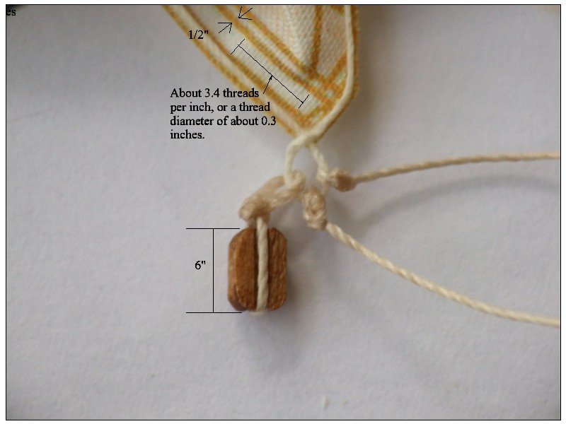
To all, Out of curiosity, what was the typical weight/thickness/thread count of cotton and/or flax sails in the 18th and 19th centuries. From what I could find on the 'net, modern sail cloth is in the neighborhood of 8 ounces with a thread count of about 148 by 160. The reason this comes to mind, again for me, the sails in the photo above look rather thick and this subject comes up somewhat often. The diameter of the threads of the sail cloth in the photo above appear to be about 1/3" in diameter, more like small rope. This is based on the assumption that the block is a 6 inch block. Even if it is a 12" block, the sail cloth thread would be very heavy at 1/6" diameter. Tom, The dog ears as separate pieces look really good. Hope you don't mind my asking but what are the gold lines on the sails? I thought maybe they represent seams or sewn lines, but seams were just sewn overlaps of the same materials. so would be the same color as the sails and I think the sewn lines would be close in color as well. Am I correct to assume these are preprinted sails in a kit? Thanks Allan
-
CM What ship/nationality/year are you building? Deadeyes and blocks this size require great eyesight and patience. Ships in Miniature by McCaffery goes into a good bit of detail on making tiny parts and is worth buying a copy to help you at these smaller scales. Allan
-
David Antscherl gives a detailed explanation making and putting in the reefing points in the sail making rigging supplement to Volume IV of the TFFM series. This little booklet is only $8 but postage to Australia is probably as much or more than the booklet. The booklet is well worth the price if sails are to be put on a model. Allan
-
Walnut and Cherry are mentioned above. Walnut is porous and looks unrealistic in texture and color for the most part. I know most kits use it but probably because it is inexpensive. Cherry is not so porous and works well, but you may not like the color which does vary somewhat even within the same board. If you do want the reddish tinge, Swiss pear is a good choice. Check out the forum here on wood and you will get a lot of great information based on others' experiences with various species. Allan
-
Hi Helli What vessel/year/nationalilty is your model and which mast and yard are you referring to? The type of truss varied with each of these. Allan
-
Don, You are free to do as you wish no matter what anyone says, but I agree with Bob's sentiment for my own builds and I really don't think I am being an elitist for TRYING to get things done accurately. (Can't say I always succeed though in the accuracy department :>)) You said that no one could call you wrong for using the wrong body plans. I disagree as the body plan is a sine qua non for a reasonably accurate hull shape. Just as a little side note the body plan is not really a framing plan as these are station lines and do not represent any actual frames unless a frame coincidentally lies right on the station line, which some do. Allan
-
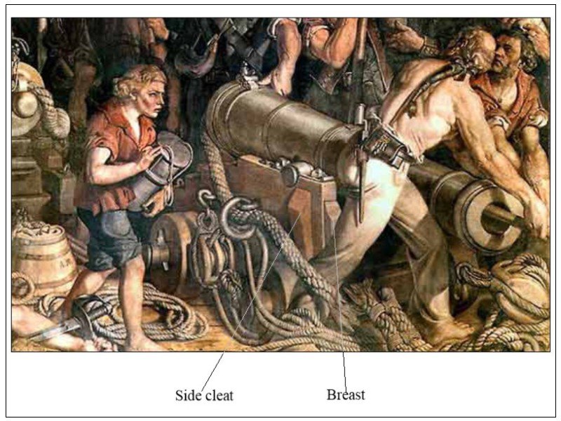
Gary, excellent and what should have been an obvious point for me that this painting depicts the QD and would have had 12 pounders in action at Trafalgar. The cleats and breasts came about in 1795 and would have been in general use on all ships by about 1805 (Caruana page 379) but he does not say if these features were peculiar to one or more sizes of carriages. The double and single block are definitely an indication of a 32 so is probably incorrect and as the Maclise painting was actually done 50 years+ after Trafalgar, it is not surprising that there would be errors of some sort in the details. Allan
-
Thanks to all of you for your responses. I note that none of the posted drawings show the breasts or cleats that came about in 1795. Perhaps these items were short lived ideas. These are shown on another section of the same painting below. These cleats and breasts are also shown on drawings in Caruana for Blomefield pattern 32 pounder carriages of 1795. I assume the gun in the painting is a 32 as it has a double block on the tackle and the lesser calibers all had two single blocks. Allan
-
Don, There are profile and deck plans for Discovery 1789 available from the National Maritime Museum. https://collections.rmg.co.uk/collections.html#!csearch;searchTerm=discovery Unfortunately they do not seem to have a body plan so this would make it pretty much impossible to get the correct shape of the hull. there are models of her out there but I have no idea on what they based the shape of the hull. Allan
-
Welcome Don, Saw your post on Leopard and look forward to see your progress with your research and build. As Leopard has been done by many others, there will be good information that may help you as well as the many drawings available as you mentioned you want to do a POF build. You may want to consider one of her sister ships in the Portland class to have something unique here at MSW. For example, there are a good number of drawings available from the RMG (NMM) for Bristol 1775 including lines and deck drawings. There are similar drawings for Hannibal, Leander, and Adamant which also have an inboard profile drawing. You may be able to find a contract for one or more of these at the National Archives in Kew which will give you scantlings specific to those ships. Enjoy Allan
-
Frame spacing
allanyed replied to Don Case's topic in Building, Framing, Planking and plating a ships hull and deck
There are drawings available that you will find very helpful as Jaager recommends. I did some checking on the Portland and Romney classes and found a "little" error. Even NMM is not infallible. https://collections.rmg.co.uk/collections/objects/87582.html shows Romney as being launched in 1972 rather than 1762. If I had known that I would have tried to be there!! Would have been like having my own Wayback machine!! There were 11 ships in Portland class by Williams, including Leopard, so there may be useful drawings and information out there at NMM and maybe on the Wikimedia site. Wikimedia has one High Res drawing of Leopard 1790 that you may find interesting. https://commons.wikimedia.org/w/index.php?title=Category:Ship_plans_of_the_Royal_Museums_Greenwich&filefrom=ISTER+1813+RMG+J5758.jpg#/media/File:LEOPARD_1790_RMG_J7335.png Allan -
Thank you Pat!!!
-
Frame spacing
allanyed replied to Don Case's topic in Building, Framing, Planking and plating a ships hull and deck
Don, If you are building as was done in the ship yard, that is, fully framed, the Room and Space for a 50 gun ship of about 1790 was 2' 9-3/8". The floors were sided 1' 2 1/2", the first futtocks 1' 2", the second futtocks sided 1' 0 1/2", the upper futtocks sided 1' 0". I not sure for Leopard, but every so many frames there were likely two that would be paired then several in between the pairs would have a space between them. Then again, if you are building in the admiralty style as seen in many contemporary models, these dimensions may go out the window. Allan -
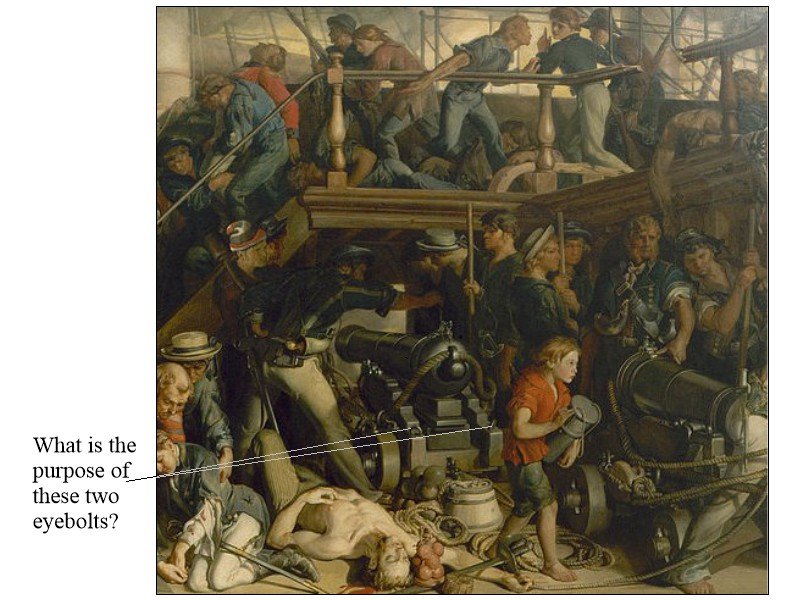
I understand that the center eye bolt in the following cropped portion of the painting by Daniel MaClise (The Death of Nelson) circa 1860, is for the training tackle, but what are the outboard eyebolts at the rear of the cheeks for? These are Bromefiled pattern carriages. I have not seen these on other carriage drawings but would like to see these on contemporary drawings if they are indeed supposed to be there. Note that there is no handle on the quoin and I understand that they were not on all quoins. Must have been a bit difficult to maneuver it without a handle. Allan
-
Just checked in on your build again and I think it is gorgeous. The details are top notch!! Allan
-
Welcome aboard Andy. Your model looks lovely and I hope you will be starting a build log on a future project. Allan
-
Druxey, Mark Porter steered me to that site and I found it to be extremely helpful. I would recommend it as a good read for anyone wanting to get into transcribing the old contracts. It's all part of the fun of the research we do before making any sawdust.
-
Rick, in my profile I put my email address in the MSN and YAHOO lines and it seems to work. Otherwise I have sent PMs with my email address in the PM itself to whoever I wanted to email me. There is probably an easier way, but I am not sure what that is. Maybe one of the moderators will add to this. Allan
-
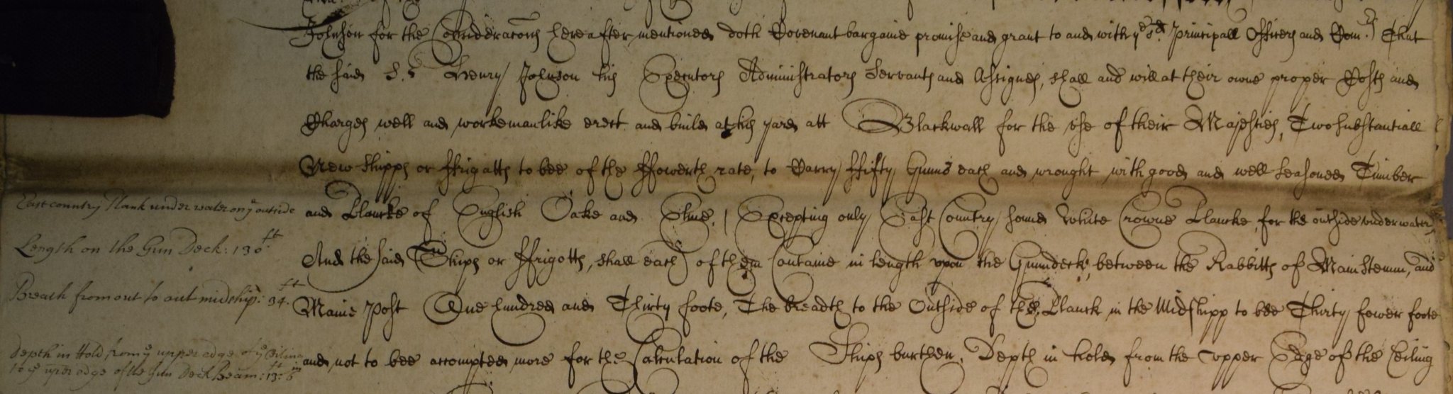
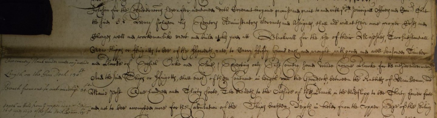
It is bad enough when reading in typeset, but when in long hand, oh my goodness, it is a chore to transcribe. It has literally taken hours for me to transcribe a single page of some contracts. Others are a breeze, mostly depends on the scribe. Oh, and don't forget the use of capital letters for all nouns, spelling compared to today, and then not always as consistent as one would think from scribe to scribe. And a number of contracts I have gone through have multiple scribes as it easy to see the different handwriting on different pages. Below is a small example. I cannot show more as there are personal use agreements for the contract as a whole which is 9 pages long. Allan
-
Larry, I would edit your post and get rid of the email address. It will open you to all kinds of spam. You can have your email address in your profile for members only to have access.
-
Sand & Sealer
allanyed replied to DaveBaxt's topic in Building, Framing, Planking and plating a ships hull and deck
Dave, Understood, they are laminating rather than assembling as was done in actual practice. The only problem is that when the wales are laid in as another strake of planking, it parallels the strakes next to it but this does not seem to be the case in the photos above. Regarding sealing and sanding I would think that this would be done after all the planking is complete rather than doing it with the second layer of planking and then the wales done separately. If you sealed the planking then glued on the laminate to represent the wales, were there any issues with the glue bonding to the sealed planks? With the sealer, I would worry that this would block the glue from penetrating and make the wales susceptible to delaminating in the future. Allan