allanyed
-
Posts
8,149 -
Joined
-
Last visited
Content Type
Profiles
Forums
Gallery
Events
Everything posted by allanyed
-
Patrick, Thank you for your introduction. Big welcome to you here at MSW. Does the Bohusian have any special meaning for you or is it like most us when we often choose because we like the way a particular vessel looks? Allan
-
 I am obviously very late to the game, but I spent a few hours on your build log yesterday as we were rained in. The praise you have received from so many of our artists out there is well deserved. Wish I could think of new words to add to the list of compliments. Learned some new tricks from your build so I got an added bonus!! Thanks for sharing your work!! Allan
 -
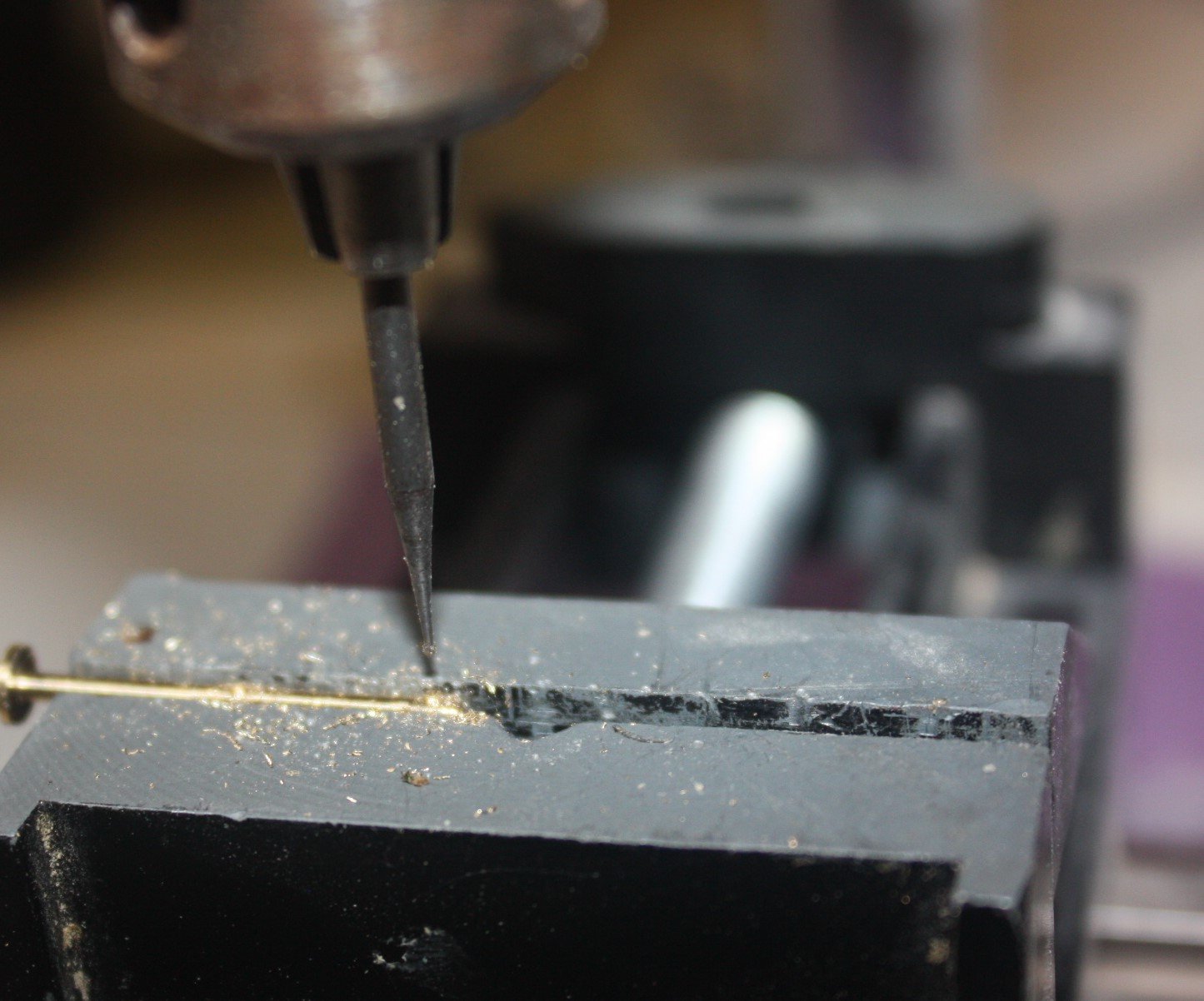
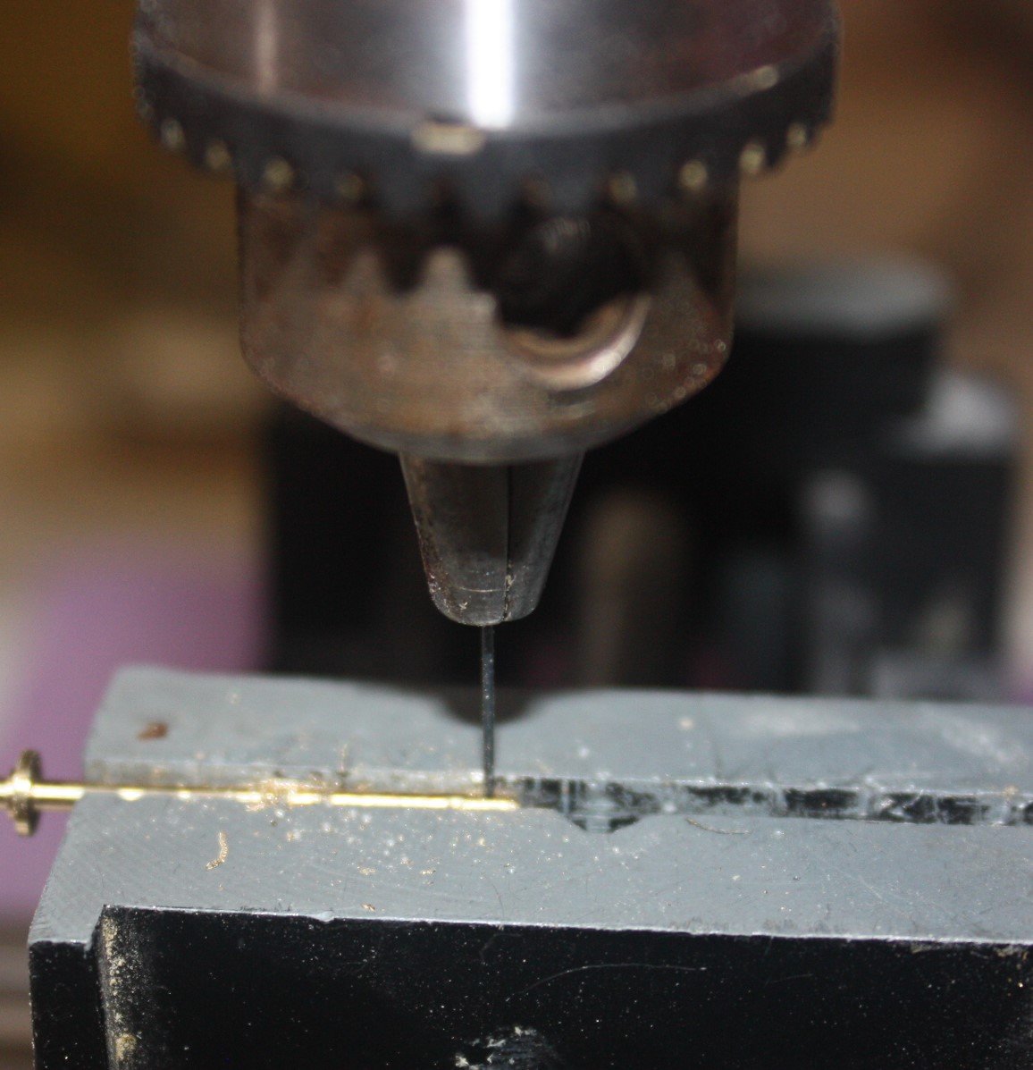
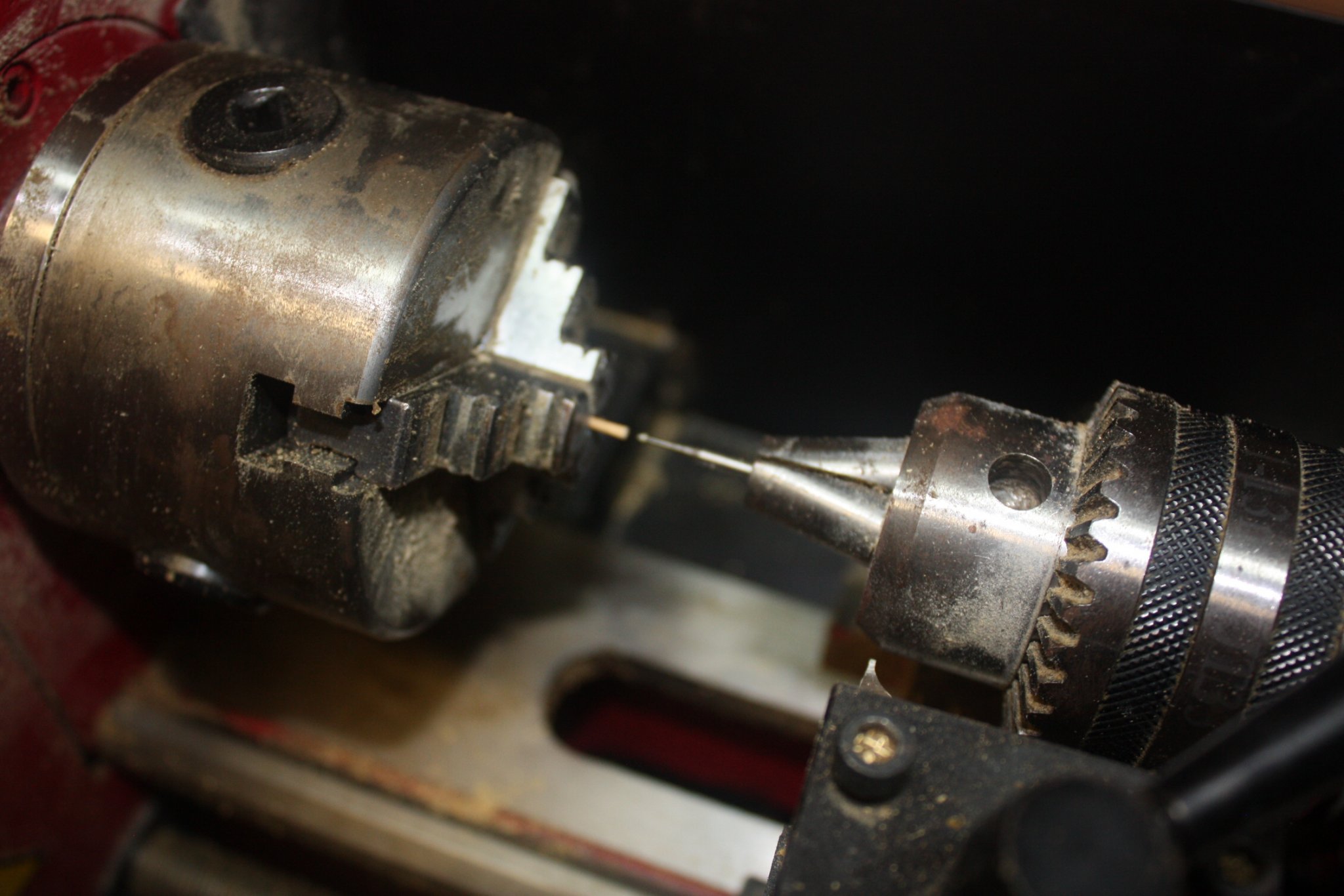
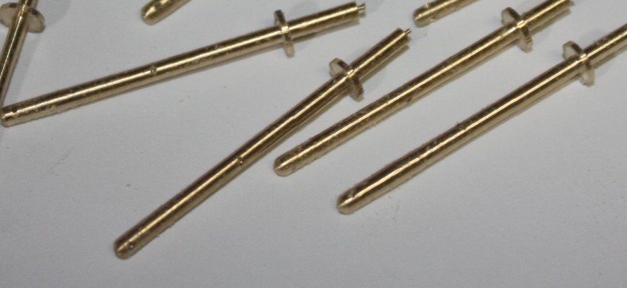
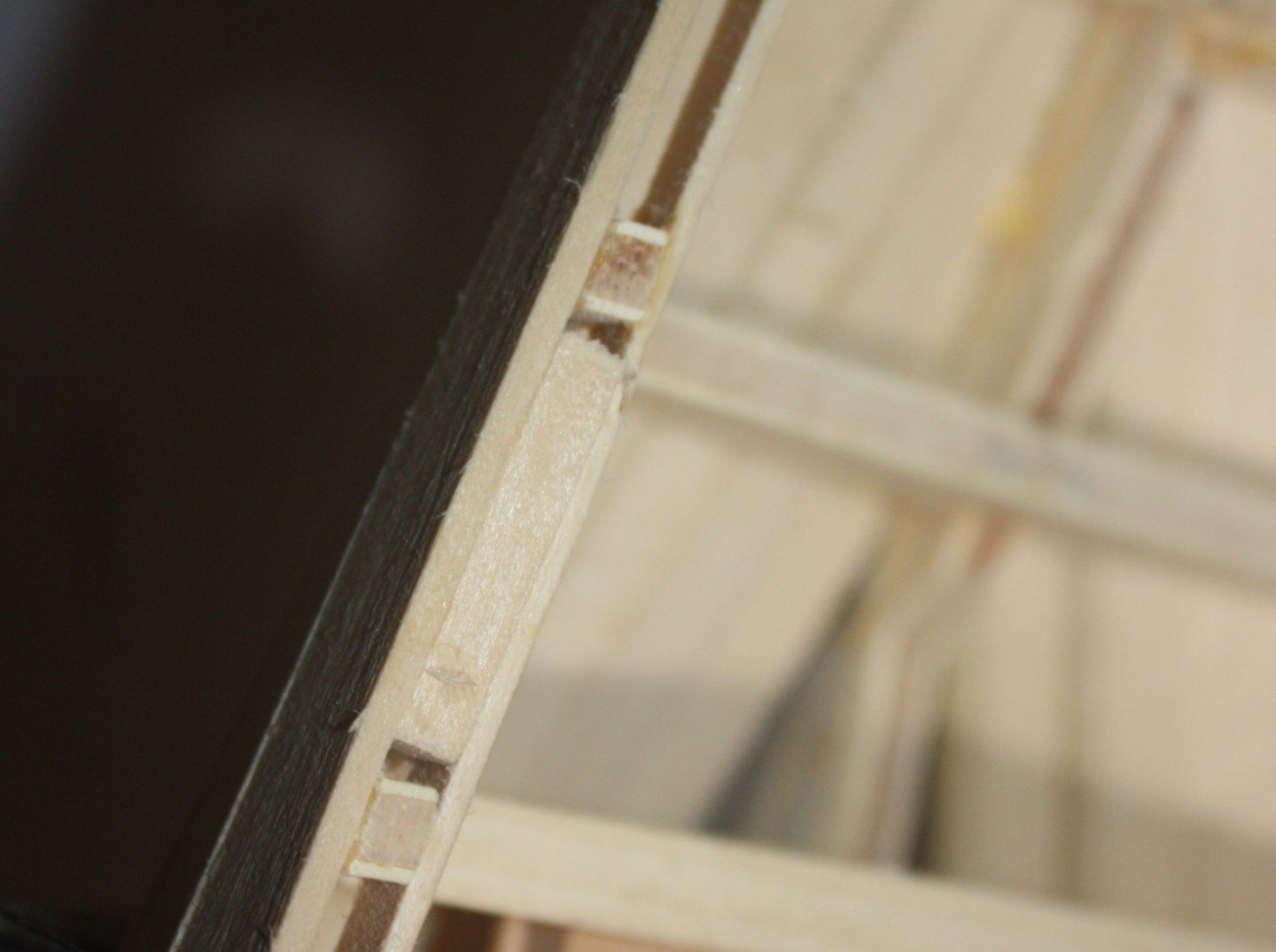
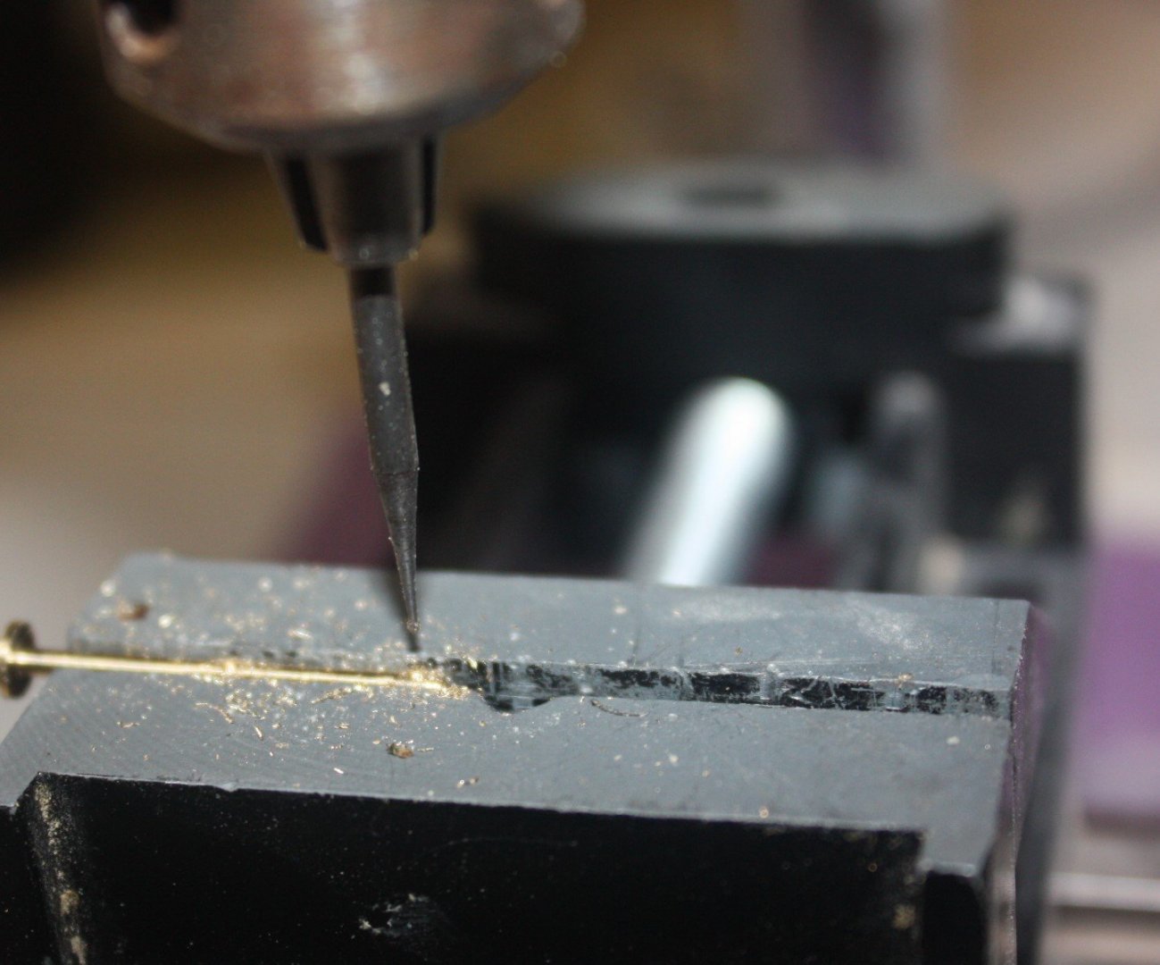
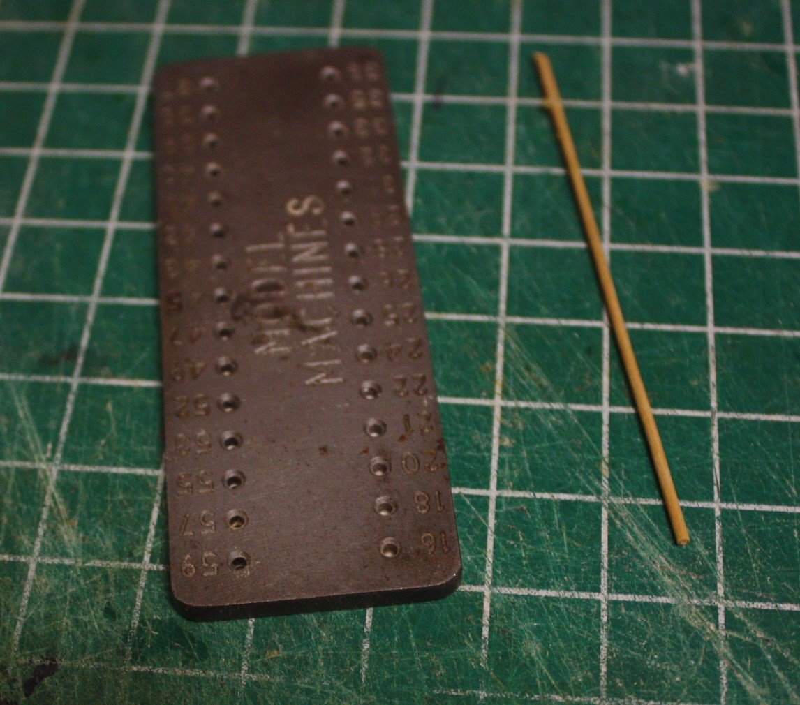
While glue dries on the hull planking strakes, I worked on the deck safety rail stanchions. The stanchions have a base plate which is screwed to the cap rail, but even at this relatively large scale, I did not like the idea of making separate base plates, drilling four holes and trying to replicate four tiny screws to secure the plate and stanchion to the cap rail. I opted to turn the stanchions and provide the base plate in this manner. In addition I left a stub that will go through the rail. To add some security, I glued spacer blocks between the frames, spirketting and hull planking in the appropriate places. (second photo) The stub of the stanchion will pass through the rail into the filler blocks and I am sure will be very secure with a bit of epoxy glue. Drilling the hole in the stanchions would be had me stumped a year ago, but having seen a "how to" on one of the other build logs it was actually quite easy. First up was make the stanchion. It was then secured in a vise on my bench top drill press. I used a small carving burr, as was done when drilling holes in the wheel rim, to create a tiny pilot hole in the center of the stanchion and another at the top. The burr has a stiff shank and does not wonder on a small curved surface like a drill bit would. I left the piece in the vise and switched out to a drill bit and drilled the holes through. Switching to the drill bit while the piece was still in the vise assured that the pilot holes were still dead center at the top. Pics below. Allan

-
Henry, the deck plan shows a slop room just aft of the marine clothing room. You may be right, one was for the sailors, one for the marines, but if that's the case, why not call it a marine slop room? So many questions, so little time. Allan
-
Jim I looked at some drawings of the orlop decks at the NMM Collections site and the marine clothing room is clearly shown on Inflexible, 1780. While it was a 64, the cabin layout is similar to what you show. I could not find a contemporary orlop drawing of a 50 but I am sure they are in their archives somewhere. Alas, I found nothing on what was inside the cabin. With the bright red seemingly the uniform of the day for the marines, I suspect this was basically a wardrobe type room, an origin or modern walk in closets, to keep things neat and orderly and away from the daily grunge that might be encountered if kept elsewhere and ruin the scarlet look. Perhaps, Victory has such a space and has been restored to what it looked like back in the day. Might be photos out there if that is the case. Allan
-
JM, You can try to simulate treenails, but at a scale of 1:75 and assumption of 1 or even 1 1/2" diameter these will only be 0.013 or 0.02" diameter. You can make them this small if you use bamboo and a drawplate, but even so, they may appear to give the hull the measles especially if they provided walnut planking which is darker than bamboo. The smallest hole on a Byrnes draw plate, which is a GREAT piece to use, only goes to 0.016. It is not so easy to make these that small even with bamboo. Just one opinion here, but I would forget treenailing at this scale. Allan
-
Thanks Mark! Thanks to you as well Grant - For about $50 including shipping, this looks like a great option. Allan
-
These are REALLY nice. I love that there are SOOOO many subjects being modeled, from canoes to First Rate ships of war here at MSW. Allan
- 84 replies
-
- 2
-

-
- nimblet
- knockabout
- (and 1 more)
-
Thanks Mark, I just did a quick search and there are two within an hour of me. Think I'll take a ride to see if they will do such small parts at a reasonable price. Allan
-
Thanks to both Kurt and Bruce! As this is brass (many piece of which will be silver soldered) I will give them a good cleaning with a pickling solution first so I hope for the best. Thanks again gentlemen. Allan
-
The interior of the main deck house is about 75% complete, lacking the bulkheads, toilet, sink, hand rails and bench cushions. I want to have a chrome finish on the rails, but not sure of a convenient way to do this. I'm going to test some brass material with Duplicolor and/or Rustoleum chrome spray finish, but if anyone has a suggestion I am all ears! Allan
-
Mark, if you have not already built the midship boats, let us know. Information on appropriate type and sizes is available and can be shared. Allan
-
Joe, I am thoroughly enjoying your build. Not something I ever thought to build myself, but your log has me thinking about the future 😀 Allan
-
Mark, If you don't mind I am curious as to which ship's boats are called for in your Sergal kit. Thanks! Allan
-
Mark, Keep in mind that Victory would have had a number of configurations depending on the year. According to W.E. May in Boats of Men of War first rates carried six or even seven boats and the type and size of boats varied between the time she was launched in 1765 and Trafalgar. The number, size, and shape would affect how they were stowed. It is possible that the quarter davits would come into play as well as stowage midships. Lavery discusses stowage at length in The Arming and Fitting of British Ships of War and gives a number of possibilities, but no solid conclusions so there may be no exact answer from contemporary sources. Allan
-
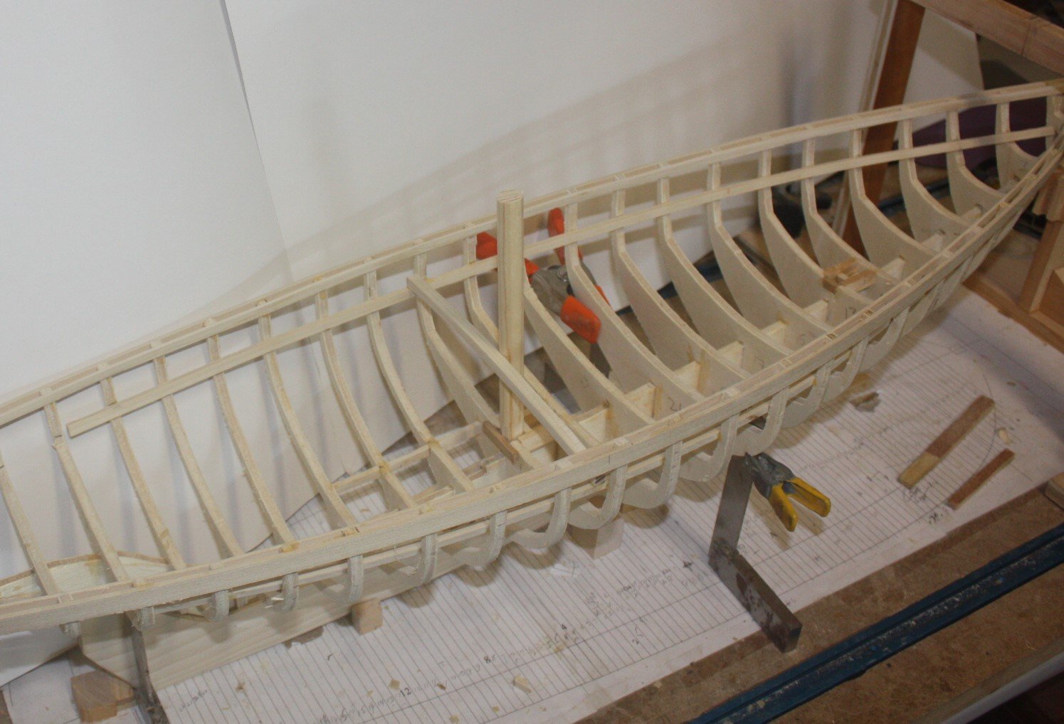
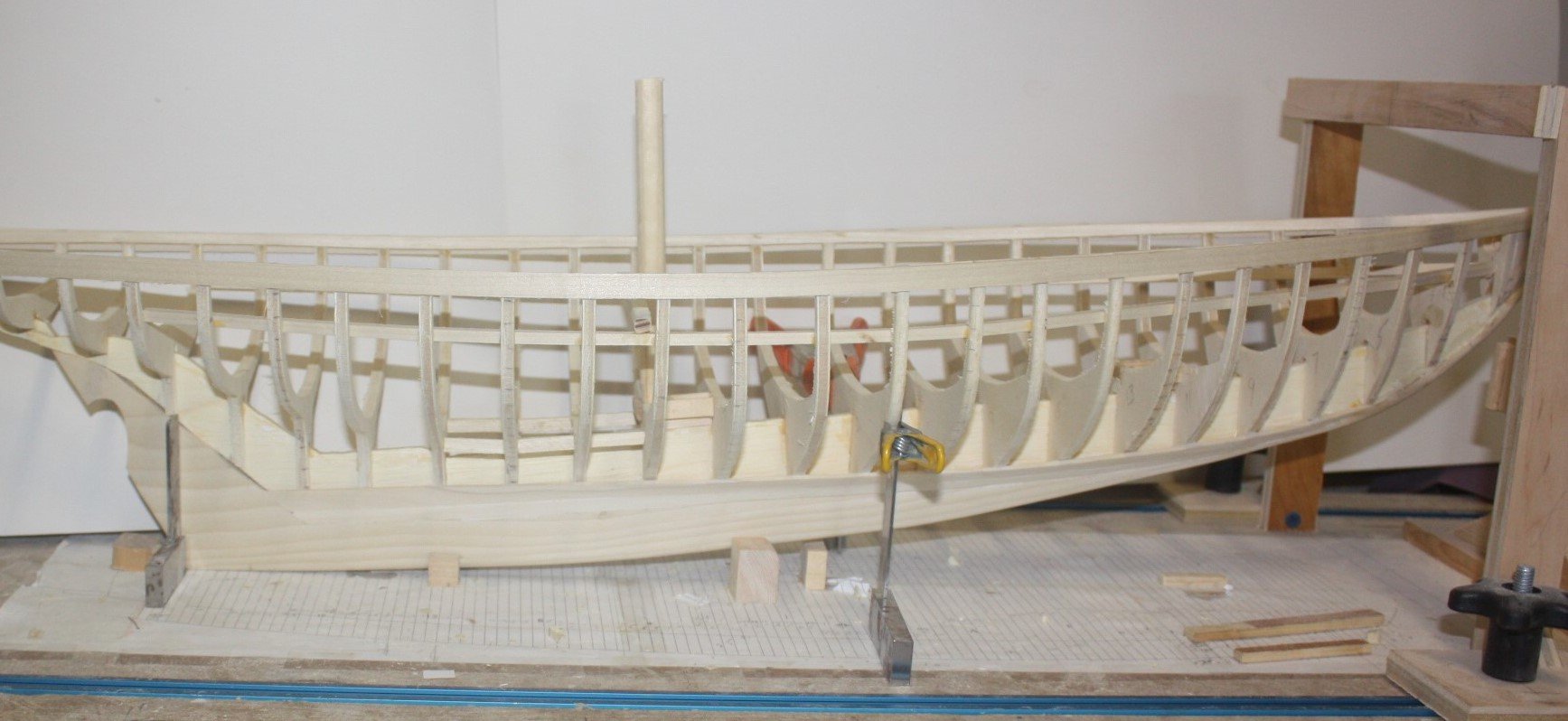
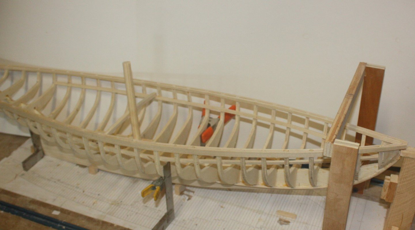
Framing is up, a couple stakes, including the garboard strakes. Mast steps are a simple affair but test mast stubs for fore and main were made to be sure the 2 degree lean aft did not cause the mast to collide with a deck frame. Of course this happened, so the deck frames around the masts will go to both sides and partners made. With the tilt of the hull a continual use of squares on the building board and a level has made it relatively easy to be sure the top of the frames are exactly the same height port and starboard. The height of the bulwarks varies between the cap rail and top of the deck clamps from bow to stern going from 19 inches down to just under 17 inches, so it was imperative that all was sitting properly before measuring from the base to the point on each frame where the clamp rests. Allan


-
Cutting and shaping masts: tips on how to do it.
allanyed replied to Peterhudson's topic in Masting, rigging and sails
An extremely detailed description on making the lower masts is in Volume IV of David Antschel's The Fully Framed Model. It will likely answer all your questions on how the mast parts are made and assembled. Allan -
Druxey How true that is. That is why in the end I think it will look pretty much the same to the observer as they cannot see how it was all assembled. Allan
-
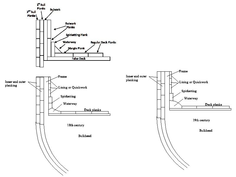
John, The odd thing I see in your drawing is the spirketting as a separate layer of planking inboard of the bulwark planking which includes the spirketting and quickwork or lining. The spirketting is part of the bulwark inboard planking and is not an additional layer. The spirketting would just be thicker piece or pieces as Jaager points out. What you have labelled as the bulwark should be the frame (or if a POB, the top portion that appears as a frame.) Using your sketch as a guide, I made some modifications that may help. When all is said and done, if you go with the way you have it drawn, it will look correct. Note that according to Goodwin, the waterway was different in the 17th, 18th and 19th century although I do not know when exactly the changes were made. The sketches I did are simplified, especially for the 19th century, but give you at least the shape of the waterway. Allan
-
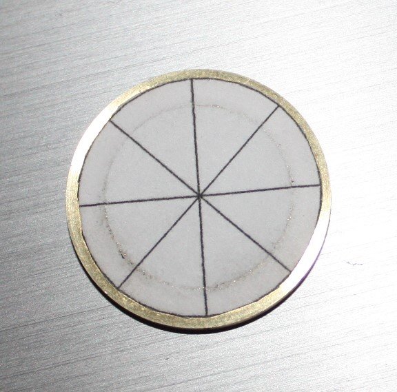
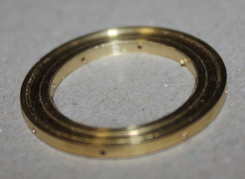
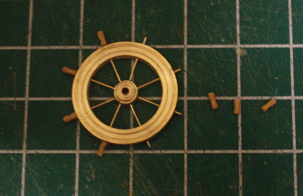
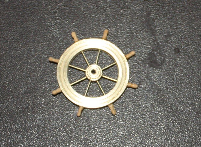
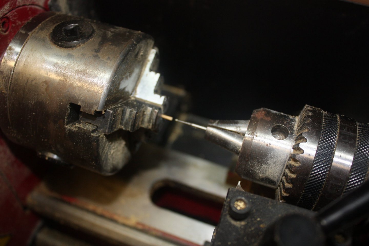
While letting glue cure, did some work on the wheel. Not terribly difficult at this scale, but still took a little extra attention. The photos explain better than words. One comment, based on what I had seen in other build logs, I used a bur to start the holes in the rim, hub, and wooden handles. It does not wander at all so a great way get the hole started before doing the actual drilling with a normal drill bit. Allan Marked rim for drilling
-
Jackie, I LOVE the byline, modeling memories or gifts. Good for you!!! Welcome Allan
-
Ernestina Morrissey by Jond - FINISHED - 1:48
allanyed replied to Jond's topic in - Build logs for subjects built 1851 - 1900
Jon These are my own thoughts, please do not take it as advice or guidance on what to do. If you take the station lines as a basis for the shapes of frames, this is an easy solution to be sure, tracing the lines in TC, printing them, and cutting out the frame parts. Is it the "correct" way to go, not really, as they can be lofted. BUT, if you use the station lines as a guide for the frames rather than lofting them, when taking into account actually cutting the futtocks and assembling the frames, beveling, and fairing, then planking, sanding and painting. how many thousandths of an inch will you be off compared to lofting each frame? I doubt anyone, including yourself, would be able to spot the difference of a model with lofted frames versus frames based on the station lines only. As to building the frames, Effie/Ernestina has double frames so two ply 1/8" thick futtocks will be very strong. If these were not laminated frames I would urge you to use castello or pear or similar. Laminated frames made of poplar or basswood will be very strong as long as the futtocks of each pair are offset just as was done back in the day. Regarding the 3 foot difference in the length, maybe speak with one of the folks that you know at Bristol and get the actual number??? Keep in mind that the plans were on paper and copied and recorded somehow before you downloaded them. Distortion, stretching, etc is common with contemporary drawings of older vessels so maybe could have happened in this case as well, although 3/4" seems to be excessive. Allan -
Hi Aaron, And when I thought there were no more hobbies in which I would like to indulge, BANG, along you come with another thing that looks like a pleasure to do. 😀 Welcome aboard. Allan
-
Lynn, Check out the wood forum here and maybe post about what you have. I am sure there are folks reading posts on that forum that may not have checked the new member forum posts. You can also just type in Sitka Spruce in the search bar at the top of the page and posts about it will come up for you. Anxious to see your build log!! Allan
-
Super welcome. Love your introduction. What an interesting profession!!! For wood, padauk, and maybe lemonwood. Bamboo for treenails. In general, the smaller the grain the better. Oak definitely not a good choice as is ash a poor choice. Not sure on some of the others. I had used teak any years ago as I had a free source and the project required teak wood work for the client. It worked quite well although a little grainy. The color is gorgeous. As to sources of anything, I assume you are in Gateshead in the UK, so hopefully UK members will reach out to you. Again, welcome aboard Allan