Check out our new MSW Sponsor Innocraftsman
×


allanyed
-
Posts
8,149 -
Joined
-
Last visited
Content Type
Profiles
Forums
Gallery
Events
Everything posted by allanyed
-
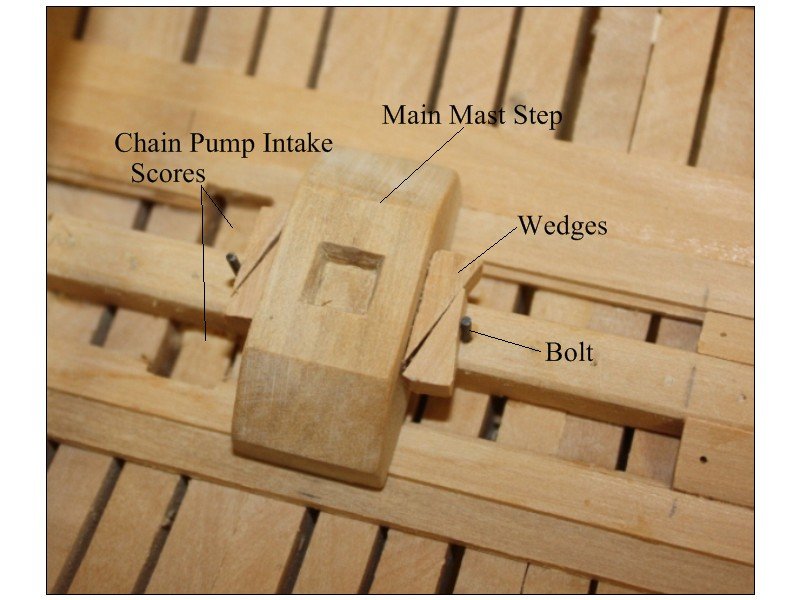
Thanks Mark, your comments make sense. Still, is the bolt and wedge system appropriate for the late 1th century? I will go that route lacking any contrary contemporary details. Thanks again Allan
-
Thank you very much for sending this Patrick. I can see a wedge that looks like it would set up the angle of main mast (stormastens). The angle of the Wasa main mast looks to be quite severe compared to Litchfield (1695) Also, it does look like it is set up to slide, same as on English vessels, but what I am not sure about is how was the the step (or saddle) for the mast locked in place. Perhaps it was not adjustable at that time and in the end, the mast on the model will never be adjusted once in place, but it is one of those details that makes things interesting. The contracts for several of Litchfield's sister ships states "To Fix Saddles in their proper places for all the Masts and of Fitt Substance and Fastenings" which to me means none would be adjustable. Thanks again, I really appreciate you sending this. Allan
-
The main mast step (saddle) was set up to slide in order to adjust the rake angle sometime in the 18th and 19th centuries, but is this example below appropriate for the 17th century? Thanx Allan
-
 Happy Birthday Gary!! Many of us have been following your build for a long time now and I for one have been impressed throughout the whole process. Great to see the update!! Allan
 -
JD, I am enjoying your build log, great work. I really like the microscope. If they were not so darned expensive, I would love to get a Zeiss or Milltek magnifier like my dentist uses. For all the pain he has caused me over the years, he should give me an old pair!!! Stuck with the old headband which still does a good job. Druxey, had to look up microtome. Maybe Donald McNarry uses one??? Allan
-
Is there a trick to making deadeyes?
allanyed replied to Schooners's topic in Masting, rigging and sails
Fascinating video, thanks for posting. Allan -
Understanding the purpose of serving rope
allanyed replied to WalrusGuy's topic in Masting, rigging and sails
WGuy In addition to those ropes that were subjuect to chafing by the sails, there are several other items that were served. As Druxey explained, it helped prevent wear regardless of where that comes from. A couple examples: the tops of the shrouds where they go 'round the mast head are served for about 8 feet below the bight around the mast itself and most, if not all, collars were served as well. Allan -
Thanks for the help/response Keith. Charles, I received your message and sent you an email. Allan
-
Just found your build log George and it has made for a fine half hour reading your log and studying the photos. Your choice of vessel is definitely a wonderful change. WELL DONE. Allan
- 81 replies
-
- 1
-

-
- egyptian
- byblos ship
- (and 1 more)
-
Degluing
allanyed replied to Zooker's topic in Building, Framing, Planking and plating a ships hull and deck
IPA is a great way to go if you can find any these days. The boss took my supply to mix with aloe vera gel for some homemade hand sanitzer when that was in short supply. Water also works well for aliphatics. Acetone (nail polilsh remover) for CA. I could not find an ingredient list for DeGlue Goo, but the Material Safety Data sheet for De Glue Goo states "Inhalation: Threshhold limit value: 10 ppm Short term exposure: 15 ppm for 15 minutes Odor threshhold 1.0 ppm Prolonged inhalation of vapors can cause irritation to respiratory tract. Eyes: Will cause eye irritation - smarting and reddening of the eye" Allan -
Types of Scarphs
allanyed replied to allanyed's topic in Building, Framing, Planking and plating a ships hull and deck
Jaager, Wales with anchor stock or similar planking are not really all that difficult at our scales. The fun would be for the clamps on the UD and GD on this model as they are specified as tabled and scarphed hook and butt. THAT is not a fun prospect. I decided to forego the tabling on this model as these will be pretty much closed in and never be seen. Maybe on the next project. Allan -
I tried the Aubrey series a few times as well but had a hard to time gaining interest. I preferred the Thomas Kydd series and Alan Lewrie series. They are fun reads but not of much, if any, use for building a model. Allan
-
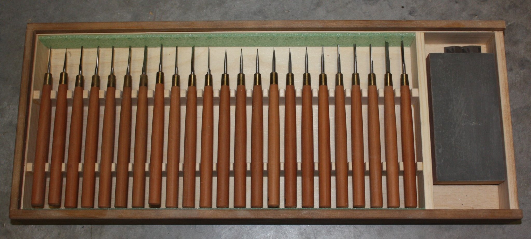
Charles, If you would like to contact him, PM me and I will send you his email address. You will not find better chisels anywhere. Allan
-
Types of Scarphs
allanyed replied to allanyed's topic in Building, Framing, Planking and plating a ships hull and deck
Thanks guys, much appreciated. Jaager, the contracts are relatively detailed in their description of the frames so no issues there. I was only in a quandary regarding the various strakes, specifically the footwaling and GD clamp. The GD is in pieces as it has a clamp and riser. I looked again at the FC and as it is only 25 feet long, a single piece would likely be appropriate. Just as an FYI, there are 6 strakes of 15" wide footwaling at the wrongheads, with two that are 6" thick lying on the chocking of the floor head and middle futtock, then one 5" on each side, then one 4" on each side. Perhaps the center strakes would be scarphed as they are to reinforce the area of the joints of the frame. The devil is indeed in the details at times. Allan -
British warships, late 1600's. The contract for several 50 gun ships of the 1690s specify that the clamps of the gun deck and upper deck are to be "Scarphed Flemish Hooke and Butt" There is no mention of the type of scarphe for the QD, Forecastle or for the footwaling. Thicknesses and widths are given, but there is no mention of scarphs. Would there be some type of scarph, and if yes, what type? Thanks Allan
-
Change Theme
allanyed replied to cog's topic in Using the MSW forum - **NO MODELING CONTENT IN THIS SUB-FORUM**
Chuck, Jim and all you hard working mods, The problem with the new look is not the new look, but rather we seem to be mostly a bunch of past fifty/sixty/seventy year old folk that despise change more and more as we get older and older. Too set in our ways. From one oldie here, great work, these changes help keep the mind working a little harder. Keep up the great work everyone, change is good!!! Allan -
Mini Table Saw recommendations
allanyed replied to captainscott's topic in Modeling tools and Workshop Equipment
Late in the game here, but If I ever need a new mini table saw there is no doubt I will go with a Byrnes saw based on so many recommendations here at MSW and my great experience with his thickness sander. In the meantime, I have 20 years or so with my Microlux saw and have no complaints at all. The only add on I purchased was the sliding fence micro adjustment unit that really zeros in on the cut width that I want. There is room to clamp on my own temporary table tops with specific guides when doing tricky work such as slotting slabs to make gratings as Bernard Frolich does them in the Art of Ship Modeling. In all the years I have had the unit I have never had an issue with the unit. Allan -
Charles, if you want to invest in a magnificent set of carving tools, I highly recommend those made by Mihail Kirsanov. I usually enjoy carving, but these chisels make carving and joinery work a true pleasure. Will there be a need for customized tools at times, I would guess this might be the case, depending on the situation, but these are probably 99% of what you would likely ever need. There are a number of members here that am sure will attest to the quality of this set of tools. Allan

-
Welcome aboard!! I hope to visit Ireland and Scotland in the next year or two with a couple golf buddies and our wives. Gotta have something besides ship models to keep the mind (and body) in halfway decent shape. Allan
-
No problem at all. Lady Eleanor probably had pretty much the same thickness planking for the entire hull with no raised strakes for wales &c, so smooth as you can on the first layer and same for the second. I would still take a look at the planking tutorials here at MSW to help you get a great looking second layer of planking down. Good luck with your build. Allan
-
Jeff, are you doing a plank on frame or plank on bulkhead? I ask this only because you mention plank on frame and these "usually" would not have two layers of planks. If you are doing a model plank on bulkhead, the smoother and more fair the first layer, the better the second layer will lie as Gregory states. I don't know what ship you are building but keep in mind that the thickness of the second layer of planking should likely vary for the wales, lower planks and quick work up high. Allan
-
Cabbie, Wow, this is a really subjective topic as we have all had different choices and experiences. Here is my take if I could only get three books with which to start. If you zoom in on something more specific regarding type of ship and shorter time span, there are many more books that can be suggested. The Construction and Fitting of the English Man of War 1650-1850 by Peter Goodwin Masting and Rigging of English Ships of War 1625-1860 by James Lees Arming and Fitting English Ships of War 1600-1815 by Brian Lavery I can go on, but these are good starts without breaking the bank. Regarding such things as rates, https://www.rmg.co.uk/discover/explore/rated-navy-ships-17th-19th-centuries gives a pretty good description. Allan
-
Charles, your options sound like a great way to go. Regarding the lead shot I have a couple models that go back 20 and 35 years when lead shot was about all that was available for bird shot. I applied several coatings of finish to the model, which included the "cannon balls" and they still look the same today as they did back then. Don't know if that will last another 10 years or 100 years, but so far so good. Allan
-
David, VERY nice dory and great story as well. Allan
-
If you have any bird hunter friends, ask if they have any number 9 shotgun shells. The pellets from one shell will last you a couple models, at least. (500 to 600 pellets in one 12 gage shell) These are a nice dark grey that is close to the look of steel cannon balls that have not yet rusted. I mentioned number 9 as the diameter is 0.08" (2.032mm) but if your model has more than one size cannon, there are common sizes of shot from 2.032 mm to 4.57mm. Allan