allanyed
-
Posts
8,149 -
Joined
-
Last visited
Content Type
Profiles
Forums
Gallery
Events
Everything posted by allanyed
-

What do I want for Christmas
allanyed replied to Worldway's topic in Modeling tools and Workshop Equipment
If you are scratch building and ripping your own planks and other parts, a Byres thickness sander is my vote. Almost every thing that is sawn goes through the thickness sander as it is so accurate. Dust is a major problem so a collection unit would be a great thing to have. Allan -
Jeff, Not sure what you are asking...... are you wanting an opinion on whether the shroud should or should not be served? Yes, it would be appropriate assuming Mondfeld is correct on the timing. Keep in mind the scale of the serving line. Using later (1624) ratios from Lees, the circumference of the stays are 0.5 the diameter of the lower mast. The shrouds are in turn 0.66 the circumference of the stays. The serving would then be 0.1 the circumference of the shroud, assuming the serving is the same circumference as the worming. Lees gives the dimensions on the worming as 0.1 but I could not find the circumference of the serving in Lees or Anderson. Running a quick calculation for a 24" diameter mast, the serving line would be about 1/4" diameter. Perhaps Mondfeld gives this dimension or another member here will have something more specific to help. At 1/64 scale, this is very small diameter line (0.004) . Remember to serve the line before you rig the shrouds. Allan
- 1 reply
-
- 4
-

-
attaching grommets to sail feet/luff/head
allanyed replied to hamilton's topic in Masting, rigging and sails
Hi Jim Welcome to MSW. It would be very nice if you would post a quick something about yourself on the new member forum here at MSW. You wrote " Do you (who are you asking) know the name of this (which) racing yacht......? There is no photo or other identifying item attached to tell us who you are asking or what yacht you are looking at. Keep in mind this subject is over 4 years old, so might not get noticed as quickly as current posts. If you are addressing someone specifically and a specific yacht, try a PM to whichever member you wish to contact. Again, welcome aboard!! Allan -
Hi Toni Sorry to be so late to the party, but I am here and have enjoyed catching up. Regarding the fashion pieces, once again one person's challenge becomes another lesson for the rest of us. Kudos Allan
-
Druxey Bristol Marine has been extremely receptive about feedback that I have been giving them. Some items above deck and below deck will likely have dimensional changes. For example, the space between the bulwarks at the entry and the bench backs just aft side of the aft deckhouse is not sufficient for a wheel chair to pass nor is there room for a wheel chair to get into and turn in the head. These will be addressed when actual building drawings are prepared by the architect. You are absolutely right in that it is extremely gratifying to find that the model has allowed me to point out some changes that they will be addressing on the final construction drawings. This had never crossed my mind when taking on the project, but it also opens my mind to the idea that no matter the source of any drawings, unless as-built, they may not be 100% correct, including contemporary drawings from NMM. Allan
-
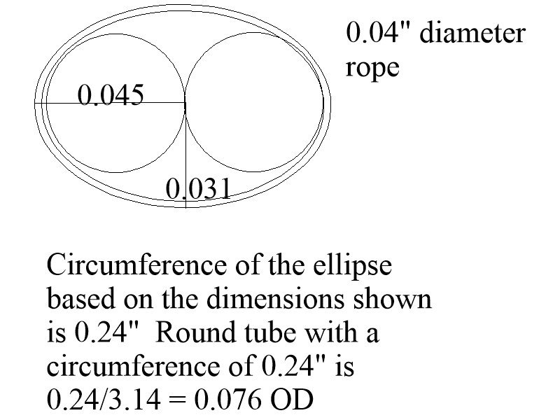
Thank you!! Keith, the trick for me was to find the diameter that can the be squeezed into an oval shape to allow two diameters of the line to past through. Knowing the diameter of the line, I drew two circles of this diameter side by side. Then I drew an ellipse and found the circumference of the ellipse. This was then used to find the diameter of the crimp pieces I had to make. Micro tubing would certainly be easier but finding the right size could be difficult. Actually making them on the lathe was not too difficult. Allan
-
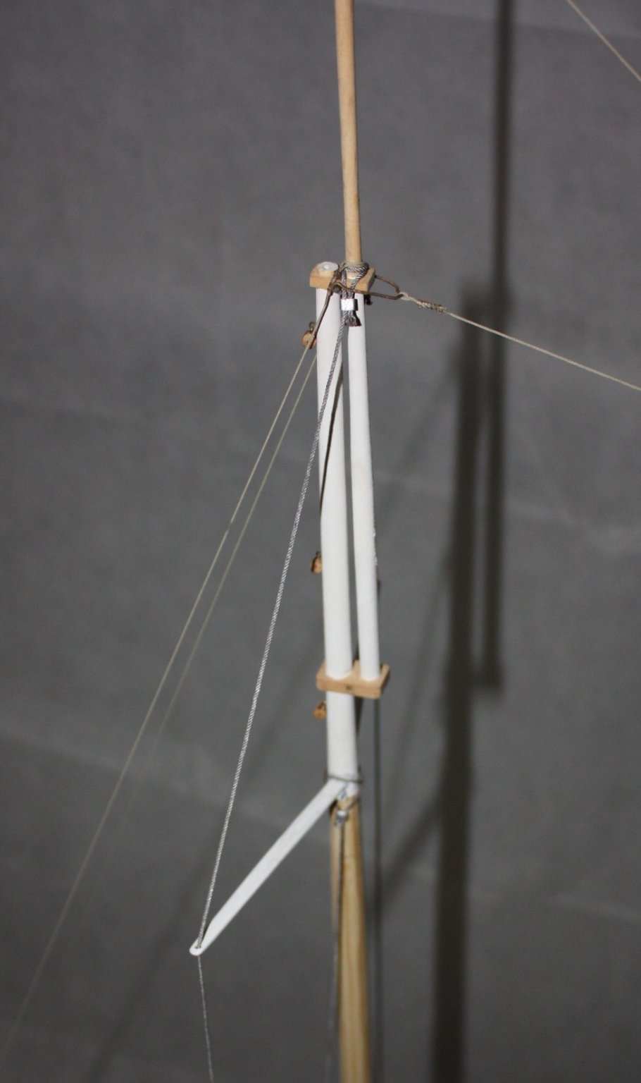
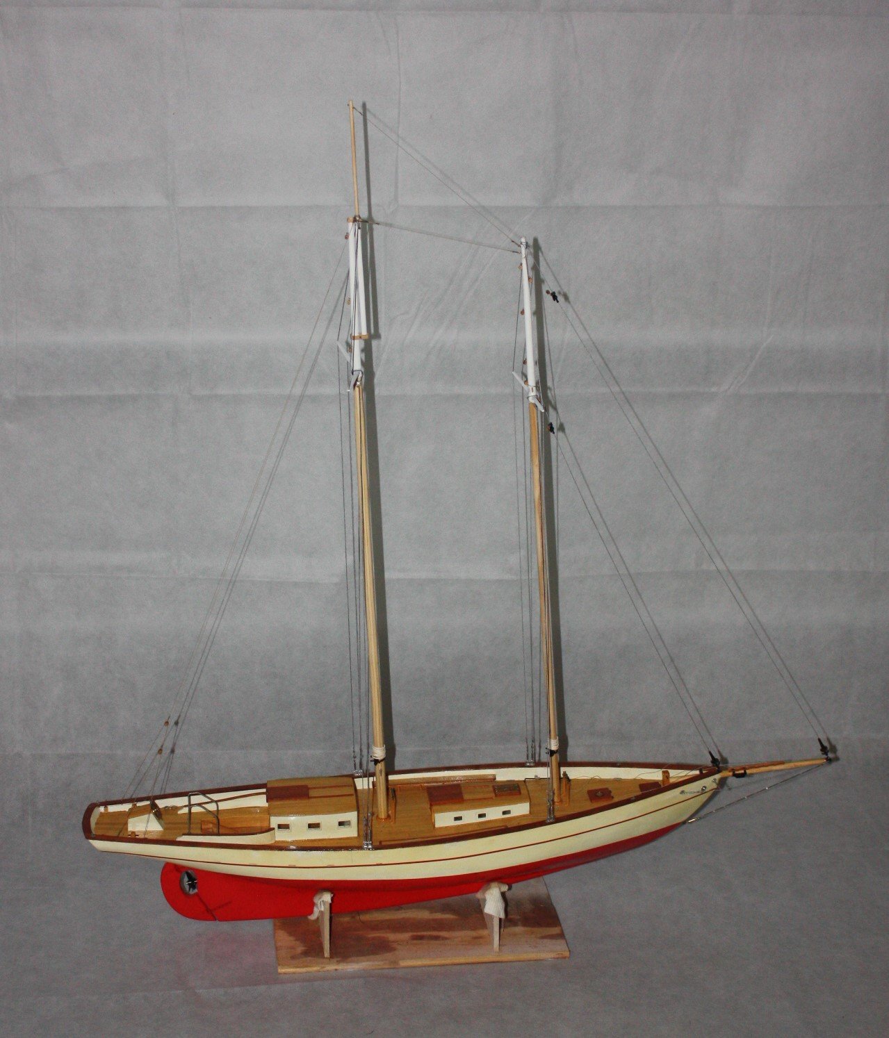
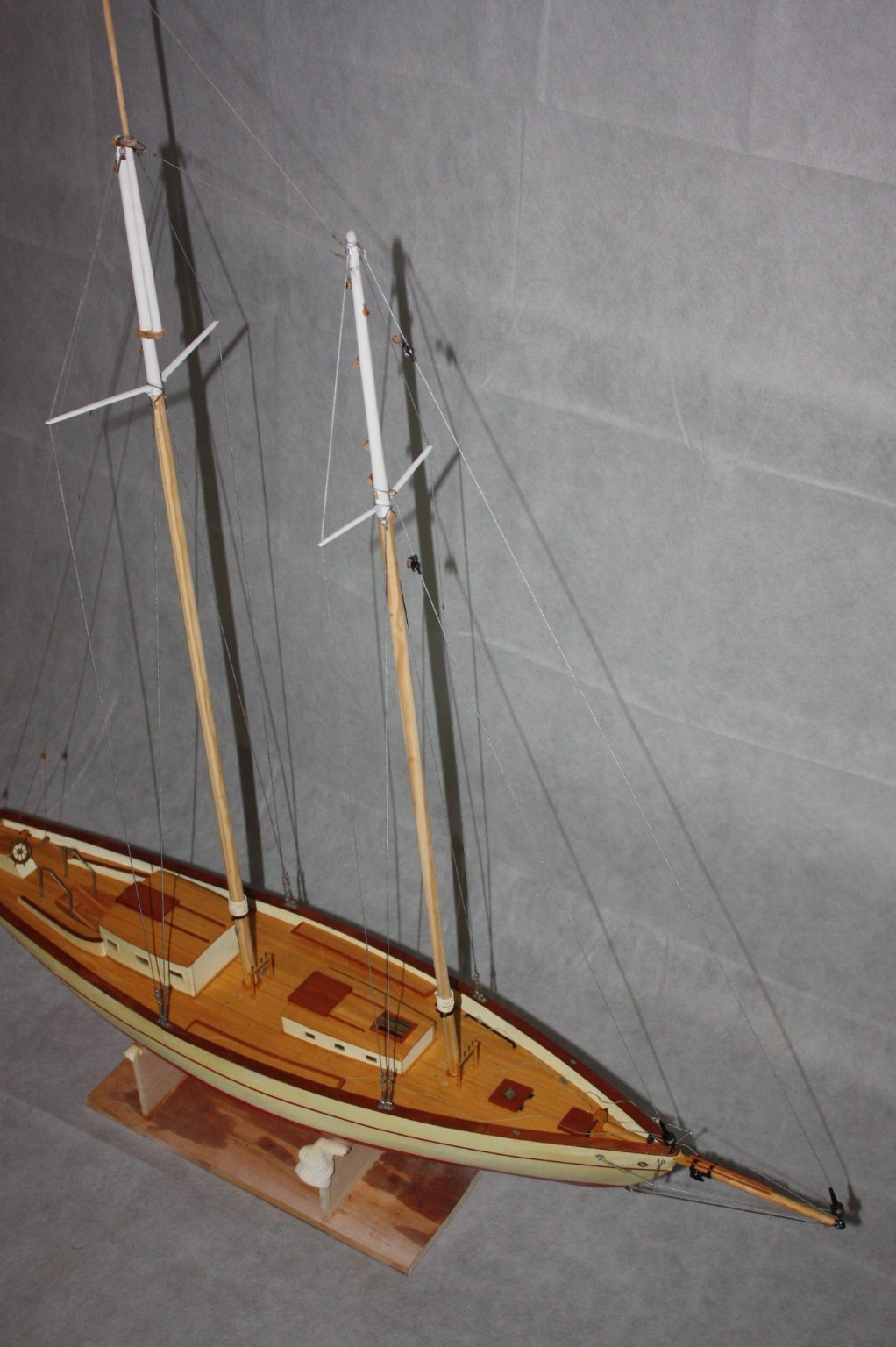
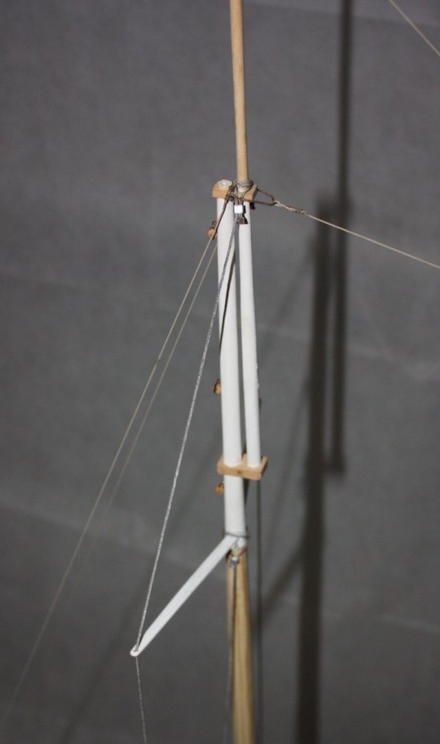
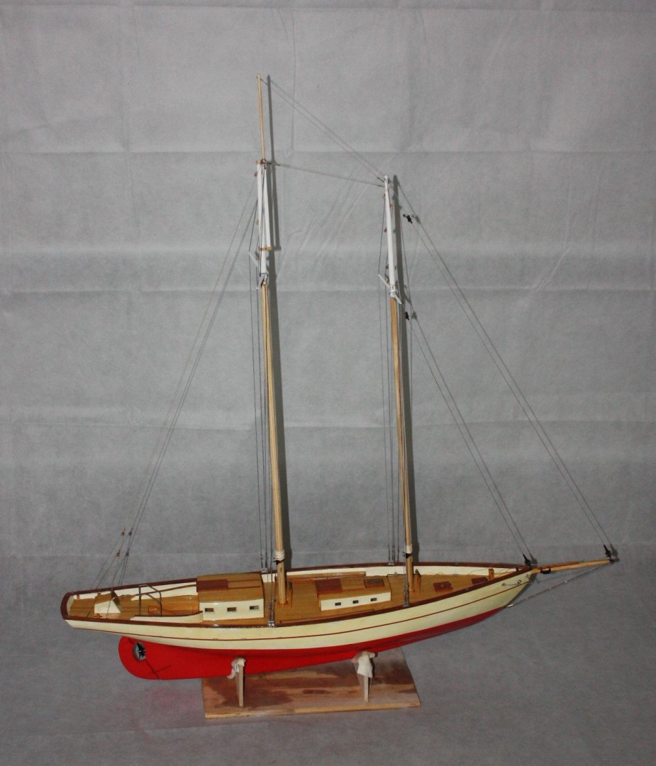
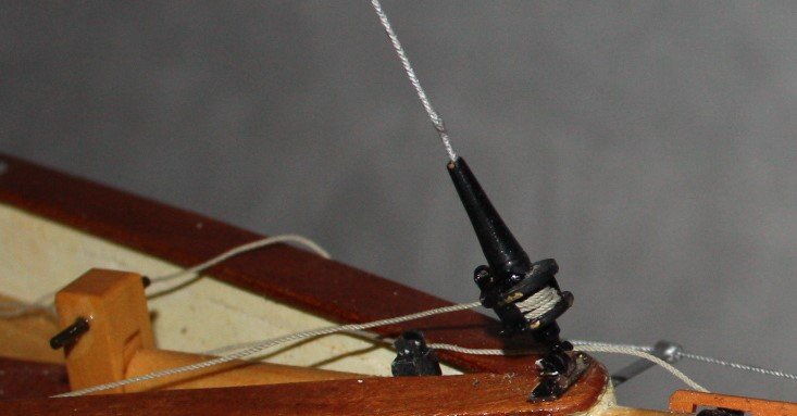
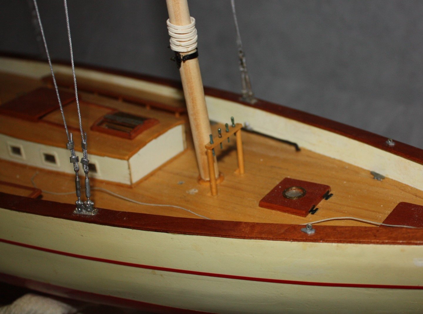
Progress with the masts made and stepped as well as the standing rigging. I worked hard at using stainless steel wire but it was not to be. I could not find small enough rope sleeves so made some out of brass on the lathe and softened them by heating with the butane torch so they could be crimped easily. After countless splinters from tiny bits of wire strands after trying to cut it nicely and not being able to keep it tight even with working turnbuckles I gave up and went to rope soaked in chrome paint. The look is really good, and it was FAR easier to work with. I still used the home made sleeves to complete the look. Note in the photos that I removed five deck cleats around the masts as I mistakenly put them where their respective blocks are to be located. The good news was that they were so secure I destroyed them when taking them out so I know the new ones will hold fast when the rigging is done. The chain shroud on the bowsprit is copper chain and relatively weak compare to brass or other materials. Lesson learned. Near the top of the foremast stays are the rollers for the furling system. The furlers themselves can be seen secured to the bowsprit and at the fore part of the cap rail. The lines for the jib and staysail furlers typically run to the cockpit on smaller sailing vessels but after discussing with the ship yard and mentioning that these would be a hazard to guests, especially in wheel chairs, even with fairleads along the deck, we decided that they will have leads only part way and end near the jib sheet and stay sail sheet traveler tracks port and starboard. Started making internally stropped blocks from Syren. These are superior to anything done by hand. The instructions call for CA glue when assembling but having little experience with it, the first set came apart as soon as I started to add the strop. I scrapped these but learned a lesson. I know CA is quick but I truly despise this stuff and went to the next set using carpenter's glue. Worked like a charm and the glue was set and the blocks ready to finish in an hour. Worked on some other stuff while the glue set, then went to finishing them by hand. This was not a problem, but a pain in the neck so I bought a $12 tumbler and it works really well. It gives an even finish all around the blocks in about 20 seconds for Syren blocks. Kudos to Chuck on his blocks!! Allan

-
Thanks for all the tips Keith. Great information!! Now that the grandkids have outgrown them, time to get some of those Legos back! Allan
-
I have had the good fortune of sending several models to Europe, three of which are aboard cruise ships which cruise in the Caribbean and European side of the Atlantic at times so there are changes in ambient temperatures and humidity even though there is climate control on board these vessels. I think a sealed case will help a lot and of course some kind of climate control. They had been at sea for a long time, one for over ten years, without any ill effects. A friend had cruised on one of the ships in the past couple years and sent me a note that he had seen the model. He commented that it looked to be in perfect condition. With the ships all shut down for many months now, I am curious to see how they faired with no climate controls during this shutdown period. Maybe it's time to book a cruise on one of the ships to see for myself once this pandemic is over. Oh, the things we are forced to do for our hobby. 😁 Allan
-
Love the use of engineering blocks to keep things square. I don't recall seeing these before so I did some searching on line as they appear to be very useful. I found too many choices to make a quick decision as they are certainly not inexpensive. Any recommendations or suggestions based on your experience would be most welcome. Thanks Allan
-
Reading/decoding Mamoli Rigging Charts
allanyed replied to robnbill's topic in Masting, rigging and sails
When you say it is a bit smaller, just use a ratio of the two sizes to come up with the lengths and diameters of the larger scale model. Even if you check the basic overall length, mast heights, and/or breadth of each they should be at the same ratio. Then again, kits are sometimes fraught with errors so the three items may not be the same ratio. Mast heights might by your best bets to find the ratio for length and the tapered diameters along the spars. At least they will then be in the same proportion. You can also look for a set of rigging plans of the Cutty Sark by G.F. Campbell which should be a big help in dimensions of the spars and proper rigging. Allan -
Wood filer
allanyed replied to Andre Gotty's topic in Building, Framing, Planking and plating a ships hull and deck
Hi Andre, Welcome aboard!! Please post an introduction on the new members forum and let us know a little about yourself. There should be no gaps between planks. It would be a good idea if you read the various articles here on planking methods that will give you a planked hull without any gaps. That said, as mentioned above, if you are painting the entire hull, no harm in filling the gaps, but, no matter how well you do this, the filled gaps may show unless you give multiple coats of paint and sand between coats to try to even things out. For tiny gaps, you can use saw dust of the wood that is used for the planking mixed with carpenter's glue or something like DAP Plastic Wood. As you are showing you are doing scratch build, better yet, you may want to consider removing the planks and replace them so there are no gaps. I know this is a pain in the neck, but it could be your best route to follow and a great learning experience. Allan -
Nails and Glue
allanyed replied to Neil10's topic in Building, Framing, Planking and plating a ships hull and deck
Hi Neil, I totally agree with Spyglass for Mare Nostrum. BUT, if you feel you need to install some kind of fastening that shows, there would be many more beams than on your model. Just putting in spikes on the bulkheads would not look correct. Also, per Spyglass's comment, if you want to go ahead with this, it would be better to make and use wooden trennals as they would appear more like wooden plugs that would be used to cover the spikes or dumps. There would likely be two through each plank at each beam, not four on every other plank and they would lie at an angle, not be in line similar to the attached. Hope this helps! Allan
-
Nails and Glue
allanyed replied to Neil10's topic in Building, Framing, Planking and plating a ships hull and deck
Neil What scale is your model? What ship is it? This could be useful in determining if trennals, spikes, or dumps were used. If smaller than 1:48, you do not need to show anything as it could easily be out of scale. Even using a sharp pencil point could have different size dots as the graphite wears down. If you are building at 1:48, the diameter of the nails would likely be about 3/4" or smaller, thus 0.015" diameter. Not difficult to make from brass rod for spikes or dumps or bamboo if for treenails. If 1:96, the diameter would be less than 0.007" I am not a fan CA, but admittedly have recently begun using it for styrene on styrene and styrene on metal with no issues. For metal on metal, silver solder or even soft solder at times. But for wood, why go to the expense, fumes, etc. of CA when carpenters glue is really better suited for wood. I have been recently told that many folks use CA because it makes the build go quicker. I never really thought of ship modeling as a speed event so CA never had any appeal for me. Just my own personal thoughts and I am probably in the minority, but you asked. No matter what you decide to try, Mark has given great advice. Do a test drive of each method on scrap material. Allan -
The drawing on the kit plans is a just a convention for a kit model. For a POB build the sprit should pass through the forecastle bulkhead between stanchions. The forecastle bulkhead itself is probably only 2" or 3" planking and could never support the sprit if done this way in actual practice. On a real ship or even a POF model, there is a bowsprit step of heavy timbers that rest again the deck beams at both the bottom and top of the step. There is a mortise in the step and the end of the sprit would be squared off to rest in the mortise. If the vessel is ship rigged the step will be at an angle. For smaller vessels with near horizontal sprits, the step would be pretty much vertical. Look at inboard profile drawings and they often show the step. As a substitute for the model, a mortise can be cut into the frame bulkhead. Allan
-
Preformed sizing for dead eye installation
allanyed replied to Runnymede's topic in Modeling tools and Workshop Equipment
Vince, as shrouds are usually in pairs, except for the swifter if there are an odd number of shrouds, I am having a hard time envisioning your methodology Can you post a few pictures? Thanks Allan -
Preformed sizing for dead eye installation
allanyed replied to Runnymede's topic in Modeling tools and Workshop Equipment
Runnymede, Thanasis posted something in the modeling tools section that may help you and a lot of us just a few hours ago as I write this regarding making seizings, and shows these with a deadeye as an example. Allan -
Hello Peter,' There is no single book in any library I have seen that will answer all questions from keel to top of the mast. But, if you intend to build a specific British vessel from the mid/late 18th century, Endeavor, there are fewer books needed to answer most questions and as it has been probably been modeled thousands of times before, you will have a wealth of advice available. If you go with something that has not be built before, or at least not very often, once you choose a specific ship or a nation and type and era, then it is pretty easy to home in on appropriate reference books. There are books on framing, fitting, rigging, ships' boats, capstans, and on and on. It may turn out you will wind up with four or more books once you choose a vessel. The style of your build also makes a difference, kit versus scratch, plank on frame, plank on bulkhead or other method. Welcome to MSW! Allan
-
I would imagine the History Channel series was far more interesting from a fact base. The Last Kingdom is a four season series and has some pretty gruesome stuff. Takes place in 800's when King Alfred was trying to form England by uniting Wessex and Mercia. Some fact, mostly fiction, but interesting none-the-less, (to some friends and me at least -not the wives - too much fighting) Allan
-
Welcome aboard Jon, Vikings seem to be a more and more popular subject. Maybe due to the Last Kingdom series??? We ALL have a lot to learn in our pursuit to build a high quality model, and this is without doubt the best place to get useful advice from so many artists. Allan
-
Bob Friedman has had health issues (nothing to do with Corona virus) the past year or so thus the responses have been sporadic. Others have had similar situations but turns out to be OK in the end. As far as payment methods, I have no idea what that is about, perhaps others here that have had success in ordering a book for shipment to the EU can give some comment/advice. Allan
-
What Davy said for sure. There is normally no correlation between the lay of the hull planking and the fore and aft curvature of the deck. Allan
-
Glue for Templates UK
allanyed replied to Some Idea's topic in Building, Framing, Planking and plating a ships hull and deck
I print items to be cut out on label paper. Cut out the part drawing just outside the lines of the drawing, remove the backing and stick it on the wood to be cut. If the wood is clean when the paper is applied it will stay on for a long time. It peels off with relative ease and the wood is clean. I usually give it a scrape with a razor or swipe with sand paper just in case there is any residual glue although if there is any there, I have never seen it. Allan -
Seawatch Books. https://www.seawatchbooks.com/ItemDisplay.php?sku=115003 Allan
-
I have had three draw plates and still have one from MicroMark which is OK for the most part. One of the holes is actually larger than the preceding one so a miscue on their production floor, and I still have the Byrnes. BYRNES IS THE WAY TO GO. I have made many many thousands of treenail strips from bamboo and pear with this plate and it never disappoints. One trick I learned some years ago (I think from Druxey) is to pull the piece through the same hole at least two or three times at slightly different angles before moving to the next smaller hole. Takes an extra few seconds, but well worth it. Allan