


allanyed
-
Posts
8,149 -
Joined
-
Last visited
Content Type
Profiles
Forums
Gallery
Events
Everything posted by allanyed
-

How to attach deadeyes to channels in the 16th century?
allanyed replied to Baker's topic in Masting, rigging and sails
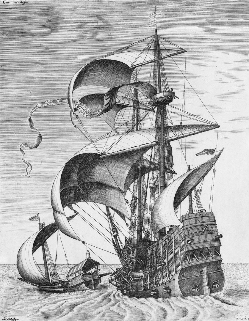
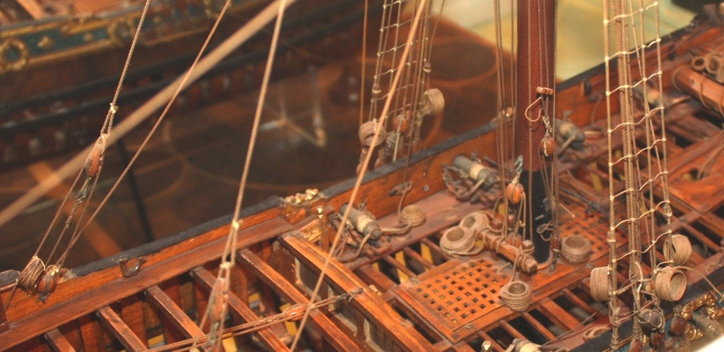
Patrick, My apologies, I was not thinking that far back. 17th century is as far back as I had photos of models so at a loss regarding 16th century. Looking at modern models including the following built by James Lees and Philip Wride in 1988 of a galleon of circa 1588 it SEEMS to not have battens, at least for the foremast. I could not find a higher res photo so not 100% sure on this model. The following contemporary drawing appears to be without the batten as well. Allan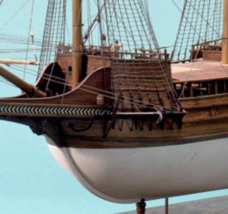
-
I have two new two copies of The Master Shipwright's Secrets by Richard Endsor, only need one. $30 plus shipping. Please PM me if interested. Allan
-
Jan, Based on how the clue block is rigged, I agree with you that would make the most sense. As stated earlier, I have only seen drawings and rigged models with the leech lines on the fore side of the sail. I just now did some more digging and based on the first photo below, the clue garnet does stay on the aft side of the sails. The leech lines can be seen on the second photo on the fore side of the sail on this model circa 1750.
-
How to attach deadeyes to channels in the 16th century?
allanyed replied to Baker's topic in Masting, rigging and sails
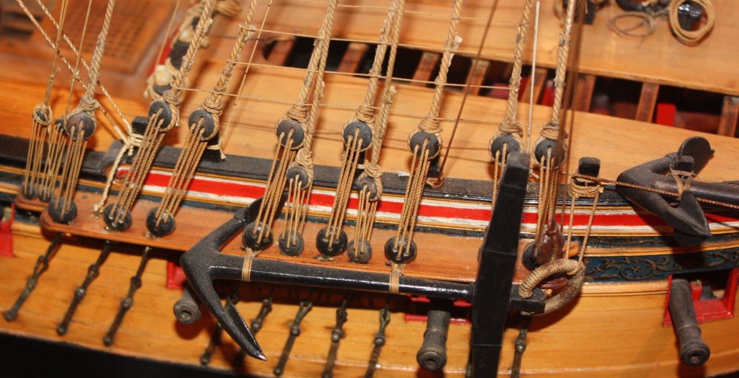
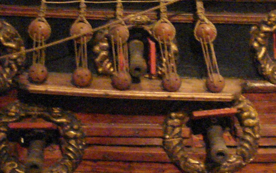
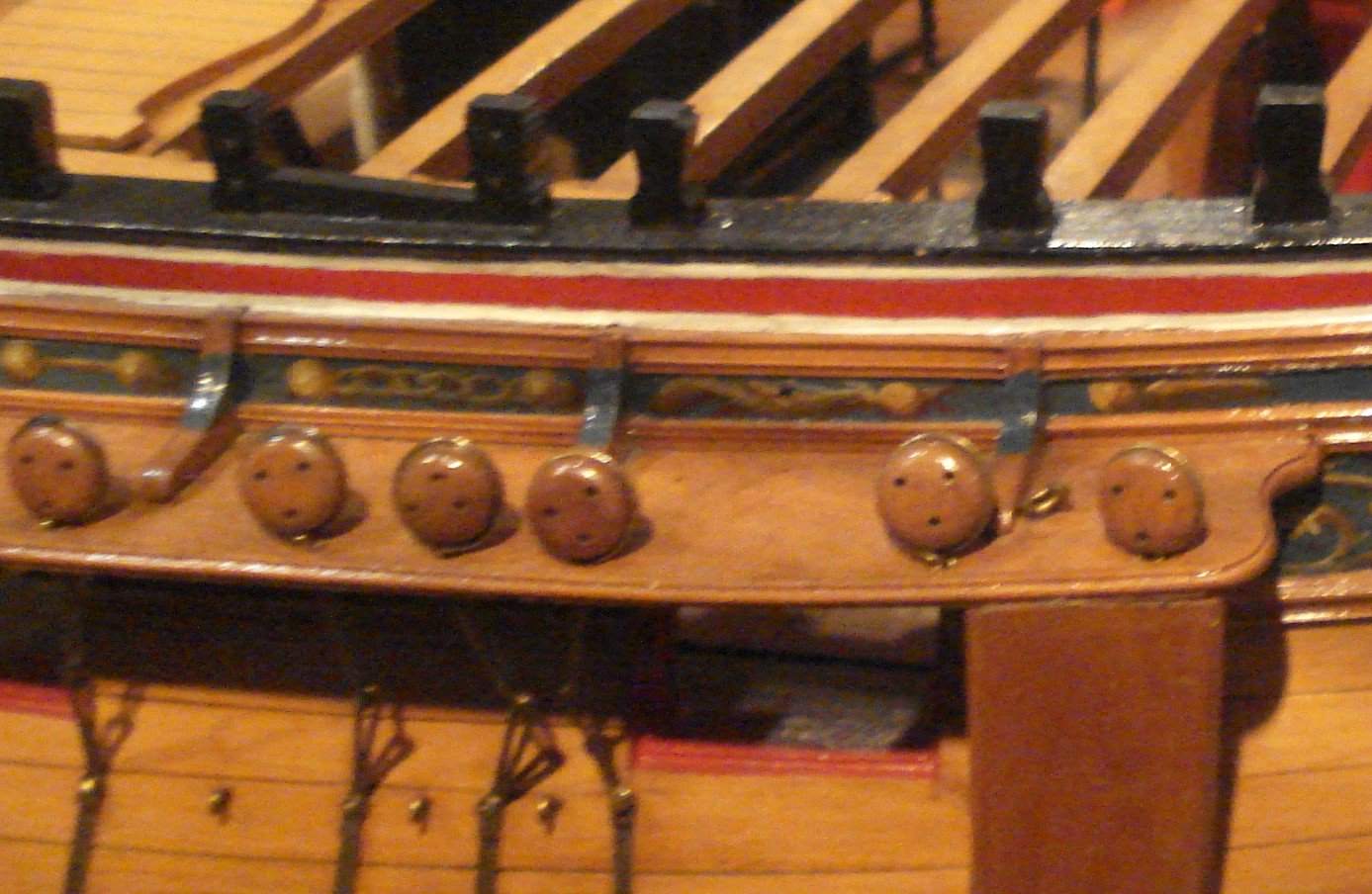
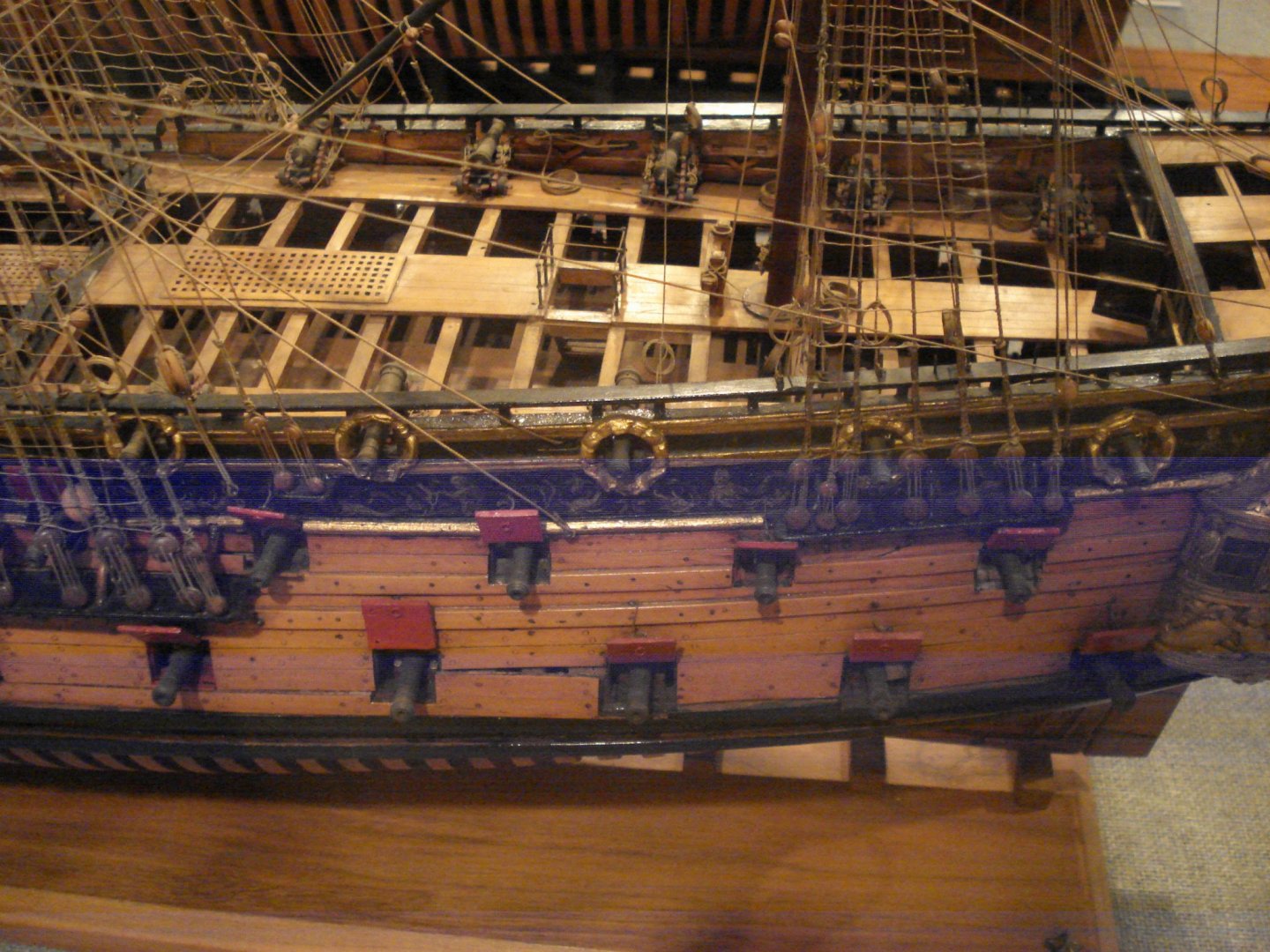
Patrick There is no need to remove the strip from the channel once the deadeyes are installed. Below are contemporary models from the 17th and 18th centuries, all of which have the molding across the edge of the channel. I do not believe these were ever removed once in place unless a deadeye or the strip itself had to be replaced. Allan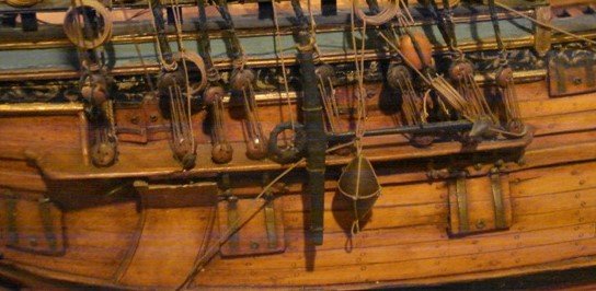
-
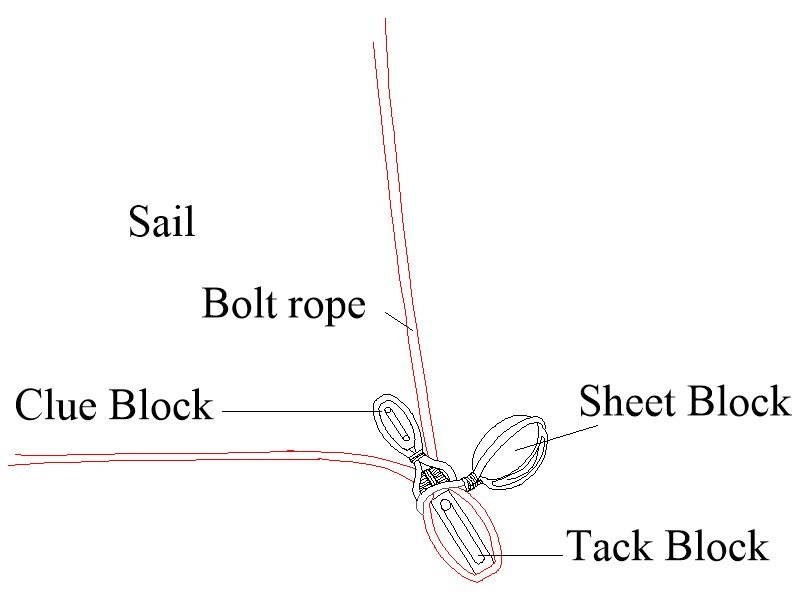
Mike, Thanks for clarifying the situation. Keep in mind that the drawing you show has the clue and sheet as the same rope for the topsail which does not make sense as they are two different lines with two different purposes. Hopefully your other drawings clarify this. Also the clue garnet would be tied to the spar with a timber hitch, not a seizing so it could be untied with some ease. For the clue, sheet and tack, the block arrangement at the clue of the sail is important. Below is probably appropriate for Enterprise. The bolt rope and clue of the sail is in red to more easily see how this is rigged. The clue block is the one through which line #19 on the drawing you posted goes. Allan
-
Mike, I am not 100% sure on which side of the sail the line runs, but assume (usually a big mistake) it is correct on the drawing that you posted. There are a lot of members here that will have more knowledge on that specifically and can confirm or correct. Are there additional drawings for the rigging of the sails? Jaager, I did not look at any other lines before and now that I have I agree they do not appear to be correct at all. While this is an American ship, the rigging should not be that different than British Navy ships of that time. On the drawing posted, the buntlines and blocks are missing on the lower sails. (there would not be any on the topgallants for ships smaller than 1st rates) The leechlines and blocks are missing (On British ships, they would have run on the fore side up to 1773 the aft from 1773 to 1815, and on the aft side from 1815. ) No leechlines would be carried on the topgallants. Bowlines and bridles are missing. It appears that topsail clue and sheet are the same line which is incorrect. The topsail clue line block would be secured to the clue of the topsail with an eye. The topsail clue line runs from the topsail yard about 3/4 in from the yard arm through this clue block at the clue of the sail, up to a block secured to the topsail yard just inboard of the standing part then down to the deck. The sheet would have a knot at the end of the line and held to the topsail clue in an eye. The sheet would go from the clue through a block under the the topsail yard near the slings, then out to the sheet block at the yard arm of the lower yard, through a center block under the lower yard, then down to and through a sheave in the bitts. Same basic problem in the drawing for the topgallant rigging. For the topgallant rigging, there appears to be a lift block on the topsail yardarm. At least for British ships, the topgallant lifts did not run to blocks on the topsail yardarms so there would not be a lift block on the topsail yards. Topgallant clue lines rove from the clue of the sail up through blocks a few feet outboard of the slings, then down to the lower top and made fast to a cleat. All in all, if you are looking for a bit more accuracy I would not use this drawing to rig your model. Mike, I would refer to one of the classic books on rigging such as Lees Masting and Rigging among others. Petersson's Rigging Period Ship Models would likely help though it is for a specific ship (Melampus 1785) and may have some additional minor differences with Enterprise 1799. Hope this helps! Allan
-
Mike The clue garnet which is what you show has the standing part made fast to the yard with a timber hitch. As the drawing shows, the line then runs down the front of the sail, through the clue garnet block and then back up the aft side of the sail to the block which should be seized to the yard a little inboard of the standing part, then down to the bitts. Keep in mind that for 1799, the tack block was first seized to the clue and then the clue garnet block and sheet block were stropped around the clue of the sail and tack block seizing, not directly to the sail, therefore the tack block will have to be seized to the clue before you can attach this clue garnet block. Allan
-
Unless someone has a contemporary drawing or photo of a contemporary model of Surprise showing crows feet were still in use in your time frame, you are probably safe to leave off the crows feet. Allan
-
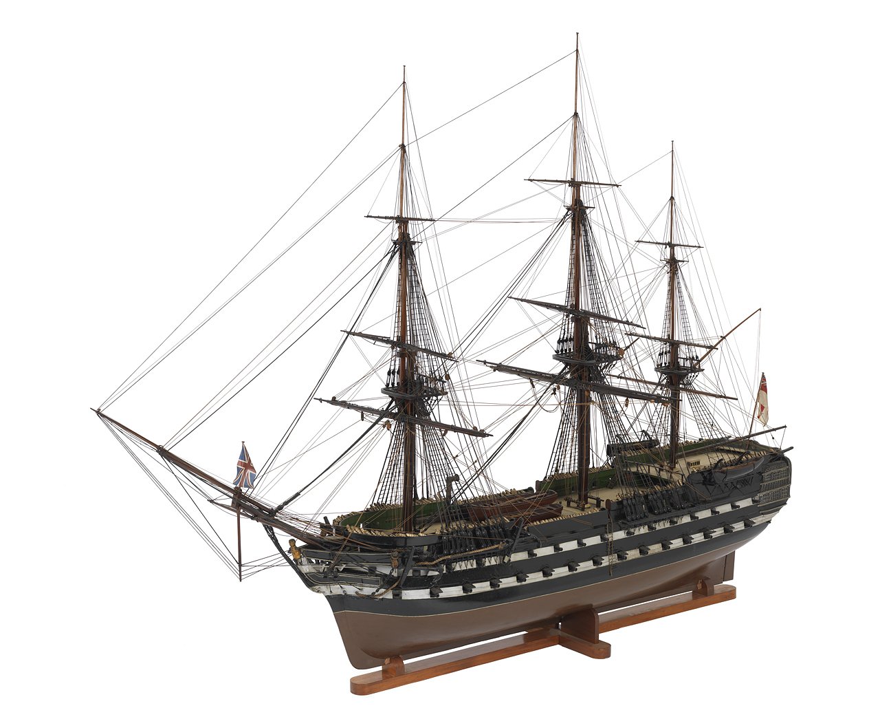
Hello Helge, I assume you are speaking about the crows feet and euphroe block. You say "without crowfeet on the top". Do you mean on the topmasts or the lower mast tops? If you could attach a sketch that would be great. Per Lees, the top masts rarely had crows feet at any time and for the lower masts they generally stopped being used by the end of the 18th century. Hastings 1818 below shows no crows feet but I found a frigate of 1805 that looks to still have crows feet. Allan
-
Victory Corel
allanyed replied to Sheerline's topic in Building, Framing, Planking and plating a ships hull and deck
Hello Sheerline, Look at the drawing on page 77 of Longridge's The Anatomy of Nelson's Ships which is about building a POB of Victory. It is very clear on how the wale strakes end at the stern. Another very clear drawing on how the strakes end at the counter is on page 17 of volume II of TFFM. Franklin's Navy Board Ship Models has numerous photos of contemporary models some of which are relatively clear showing the same construction of the end of the wales. You can see something similar in planking expansion drawings such as the one for Squirrel (1785) on the NMM Collections website. https://collections.rmg.co.uk/collections/objects/83495.html As a side note, I believe the lower wale on Victory actually had four strakes of anchor stock planks. Probably just a kit error that you can fix if you wish. Even so, it does not wrap around as you correctly surmised. Allan -
Down-sizing rope ratio compared to the proper scale
allanyed replied to Sandor Laza's topic in Masting, rigging and sails
Yes Sandor if the mast diameter is 12mm the main stay should be as you wrote, 1.91mm diameter. I guess the appearance being too thick is really how you see it, but based on Lees, at least for British ships, 1.91 is correct. As the closest you have is 2 mm, it will appear too large by 5%. But, if you go to 1.6mm it will be undersized by 16%. Your choice in the end. Allan -
Down-sizing rope ratio compared to the proper scale
allanyed replied to Sandor Laza's topic in Masting, rigging and sails
Sandor, At least for British ships of war, all standing rigging (except ratlines, robands, gaskets, and brails which are usually a given fixed circumference) can be determined as a ratio going back to the diameter of the lower masts. Running rigging can be determined as a proportion to the appropriate stays. The proportions also vary with the year the ship was rigged. To which line are you referring, what ship, year, and to which scale are you building? Allan -
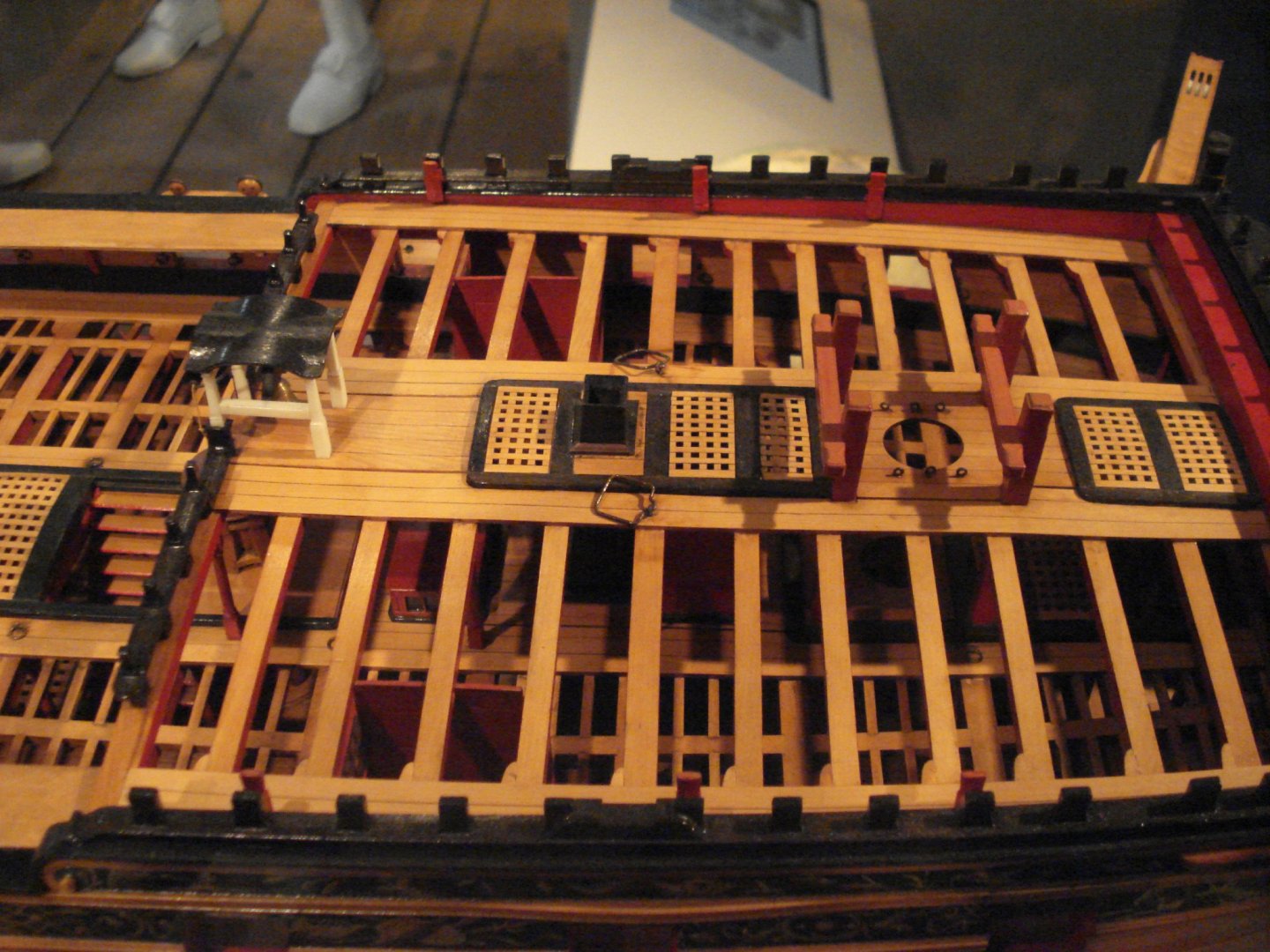
Phil, your comment on smaller vessels made me curious. I looked at photos of the contemporary model of the royal yacht Henrietta (1670) and the gratings seem to be flat or possibly conform to the rounding of the beams. This may also have to do with the era. I believe the coamings and head ledges rose above the flat of the deck much higher as time went on. The following are the Henrietta, a fourth rate of 1705 and the Prince Royal 1773 Allan
-
Ken, If you have not already seen it, try to find the documentary they did with Darryl and his team in Greenland where they tried to resurrect the B-29 Kee Bird. 99.9% done when disaster struck. Allan
-
Hi Henry Miriam's dictionary is not a nautical dictionary so probably not really applicable. Rounding or round up is the correct term for the curvature of the beams athwartships (when looking fore and aft.) Look at the scantlings in the Establishments, Steel and the Shipbuilder's Repository and you will see that each deck for each size ship is described to "round up" or have a "rounding" a specific number of inches. In addition, if you look at contemporary contracts, where this curvature is specified, it is referred to as rounding. Camber is not a term used anywhere in these contemporary sources even though the definition does seem to fit. Allan
-
I just spotted this build and was VERY happy that I did. While I have not built a plane model in 60 years, it may be time again. The reason for this is that your build brought back memories of Darryl Greenamyer (RIP) and his Red Baron 104. (Darryl was also a test pilot for the SR71 at the Skunk Works), and flew all manner of planes from Mustangs to Bearcats. I had the good fortune to meet him several times and worked with his team to provide the paint for the Red Baron as I worked for PPG at the time. Even got a chance to sit in the cockpit for a minute. Several of my coworkers and I flew in to Tonopah and Mudd Lake for the four pass low altitude speed record run October 2, 1976 which the French officials messed up, but it was a thrill of a lifetime. He did make another run later that they got right and the record still stands at 998 mph although the early run was a bit faster. The heartbreak was when he had to ditch the plane after a test run for the altitude record for which the Red Baron was specially equipped on the nose with steering rockets. Long story short, his gear did not come down and lock so could not land. He was near Edwards at that time and they put him on a crash line and had him bail out. With all the talk of color schemes, if I do build a 104, the following is what I would go for having had a chance to be part of that little bit of history. Below are pictures of Darryl and the RB and the RB itself. Allan
-
I Googled "9mm ball bearings" and got 1,250,000 hits. First one that popped. https://www.ebay.com/i/223322251035?chn=ps&var=522112134679&norover=1&mkevt=1&mkrid=711-117182-37290-0&mkcid=2&itemid=522112134679_223322251035&targetid=940197478314&device=c&mktype=pla&googleloc=9012276&campaignid=9343999134&mkgroupid=101452701304&rlsatarget=pla-940197478314&abcId=1139336&merchantid=112258805&gclid=EAIaIQobChMIhJPbod2n6gIVQuG1Ch3FQgrKEAYYAyABEgK-bvD_BwE Allan
-
What do baby formula and jeans have to do with model ship fittings? Mods, seems to be getting political.......
-
Daliab, I assume you are speaking about the cannon barrels not the casks? For the cannon balls, which guns? I believe she carried 32, 24 and 12 pounders. Assuming the 12 pounders on the upper deck, and your scale of 1:78, the diameter of the cannon balls would be about 0.058 inches (1.5mm) Even the smallest bird shot (number 10) is a little bit too large (0.070 - 1.7mm) You may be able to find micro marbles (color coated glass) that are close as they are available at 1.5, 1, and 0.5mm diameter. Allan
-
Regarding British fourth rates. I have found details on the construction of wells and shot lockers in several "modern" sources, with only slight differences between all sources, save one. The lower portion below the orlop is relatively straight forward in design and very similar in all cases, but my question is regarding the upper portion on the orlop deck. At some point the slats were installed as louvered pieces to allow air circulation. For earlier vessels, circa 1600 through early 1700's, at least one drawing that I have studied appears to have these slats the same as below the orlop, that is, not louvered. Is one method or the other correct, or would both methods have been used during these times? T.I.A. Allan
-
- 1
-

-
Securing upper yard halyards to yard
allanyed replied to Richvee's topic in Masting, rigging and sails
While the Soleil Royal was a war ship of 1670 and the KC is a whaler in 1856, the principals should be similar. Lees shows the tye(s) to be secured either with a single at the center or double depending on the era and spar. The double tye would allow you to secure them outside the truss/batten as you suggest. It is possible that these relatively small yards may not have had battens at all, but rather slings and single tye/halyard. Allan -
Tony, As this is your first post, welcome to MSW!! Perhaps you could post a little intro about yourself in the new members section. Regarding your question, if the parts are wood, don't use CA. Welcome again. Allan
-
Securing upper yard halyards to yard
allanyed replied to Richvee's topic in Masting, rigging and sails
Rich, These "battens" look just pretty much like LT Green's patented truss used on some ships starting about 1830. Lees describes these but only with the ring and eye. It was as you describe and they were for topsail spars, not the topgallants. I really have no idea on how this would be rigged unless the kit is wrong and no truss (batten) actually was used, but rather slings and/or rope trusses. Hopefully members here with more knowledge on whalers of the day can help. Allan -
Securing upper yard halyards to yard
allanyed replied to Richvee's topic in Masting, rigging and sails
Rich, Not sure this would apply to a whaler like Kate Cory, but here goes. Can you post a picture of the timber batten? Is it actually more of a rigid truss or just a batten? Perhaps these upper yards would have slings and/or a rope truss. There are no knots, but rather they would be have an eye on each end of the sling. Simple sketch follows: Allan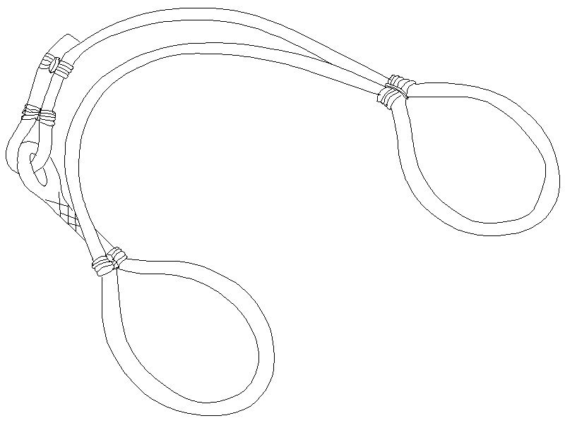
-
Blackening brass advice
allanyed replied to Bossman's topic in Metal Work, Soldering and Metal Fittings
Boss, If the culprit was not pickling and cleaning long enough, the contaminant may still be there. If you have a small wire brush wheel for a rotary tool, I would use that first and get back to bare metal then pickle and degrease. If not, you can try to just pickle it again, then clean with the acetone before re-blackening. I am pretty sure most of us have had the same issue at times and these methods have worked for me in the past. Allan


