allanyed
-
Posts
8,149 -
Joined
-
Last visited
Content Type
Profiles
Forums
Gallery
Events
Everything posted by allanyed
-
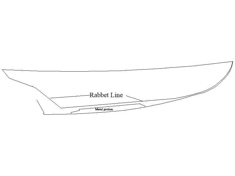
 Hi Roger, There is no false keel like I have built but there will be a keelson on top of the frames on the actual vessel. As the model will be fully planked, I decided to put in the false keel similar to kits with POB builds rather than fully frame her and have the keelson. I guess I could just call the false keel on the model a keelson which would be more accurate. Below is a cross section of Ernestina and similar to what actual BB65 would look like regarding the framing, keel and keelson and a clip from the BB65 drawings showing the rabbet line and metal portion of the keel. BUT, to be sure, I will check with Bristol Marine. Thanks for the heads up! Allan Below shows the rabbet line and metal portion of the keel on the BB65 as taken from the original drawings.
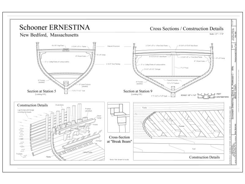
-
Druxey, Interesting is an understatement, so far. Now all I need is to find a wheel chair in 1/24. I did find a toilet, sink, and mirror in 1/24 that will go into the head. Just need to "engineer" a way to easily remove the top of the deck house when the time comes so they can see this feature with the ramp and hand rails to make it handicapped accessible which was the idea behind Bristol Marine building this schooner. More fun down the road when it comes time to make a jib furler and other modern appurtenances. Makes for a good excuse to go to the local marinas and see them up close. Anyone out there have good experience with wire rope for standing rigging? I understand how these should be rigged as they will be attached to turnbuckles, but I have no experience actually installing. I found the equivalent of 1/4", 1/2" and 1" wire rope sizes, and more, as well as compression fittings for the large size rope which will be about 0.04 diameter. It is stainless steel 7 strand rope from McMaster Carr, so getting the material is not a problem. If there are any "tricks" or advice I would love to hear about it. Allan
-
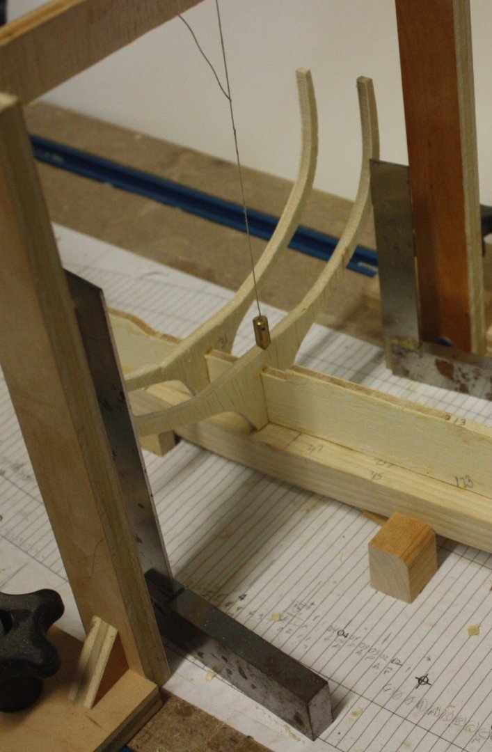
And so the frame raising begins..... I had a framing guide from another build that is on hold for now on my build board. I left it on as it is sufficient to check that the frames/bulkheads on the Boothbay are square to the keel. I use a square on each side of the frame to be sure the frames are perfectly vertical and square to the keel. I made a small plumb bob that hangs so I can also check that the frames centered on the keel as well. A quick check of the height of the top of each side of the frame is done to make sure it is not tilted athwartships. First two frames needed no trimming to keep them square in all directions, but there are 22 more to go so that may very well change. Couple more photos below. Note that I use label paper when printing the frames. I can then peel the backing and apply it to the wood without glue. Much cleaner than gluing which can lead to stretching of the paper as well as bubbles of air under the paper and a mess to clean up, and this allows having much cleaner lines than the alternative of tracing onto the wood. The paper can be expensive, but I found a relatively cheap source on line so it was not a wallet beater compared to the brick and mortar stores like Staples or Office Max. Allan \
-
If it does not go well Jon, it is your doing as you started the the whole process 😀😀 Seriously, thank you very much for setting this whole thing up. Thanks Mark! Yves, the sailors may not be a bad idea, but better will be a wheel chair which I am looking for in this scale as the reason for this particular schooner design is to have access on board and below to the head by wheel chair. It will be more evident as the build progresses. I have found them in 1/12 scale but not 1/24 so far. Allan
-
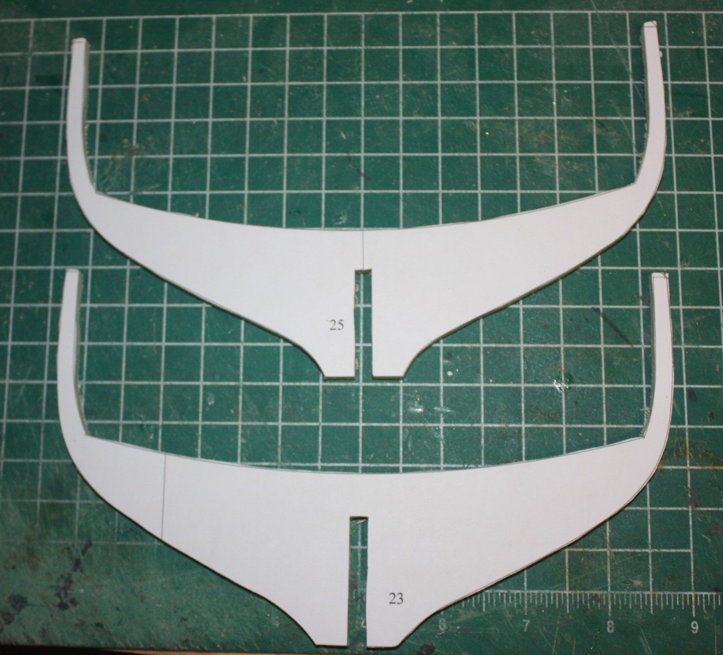
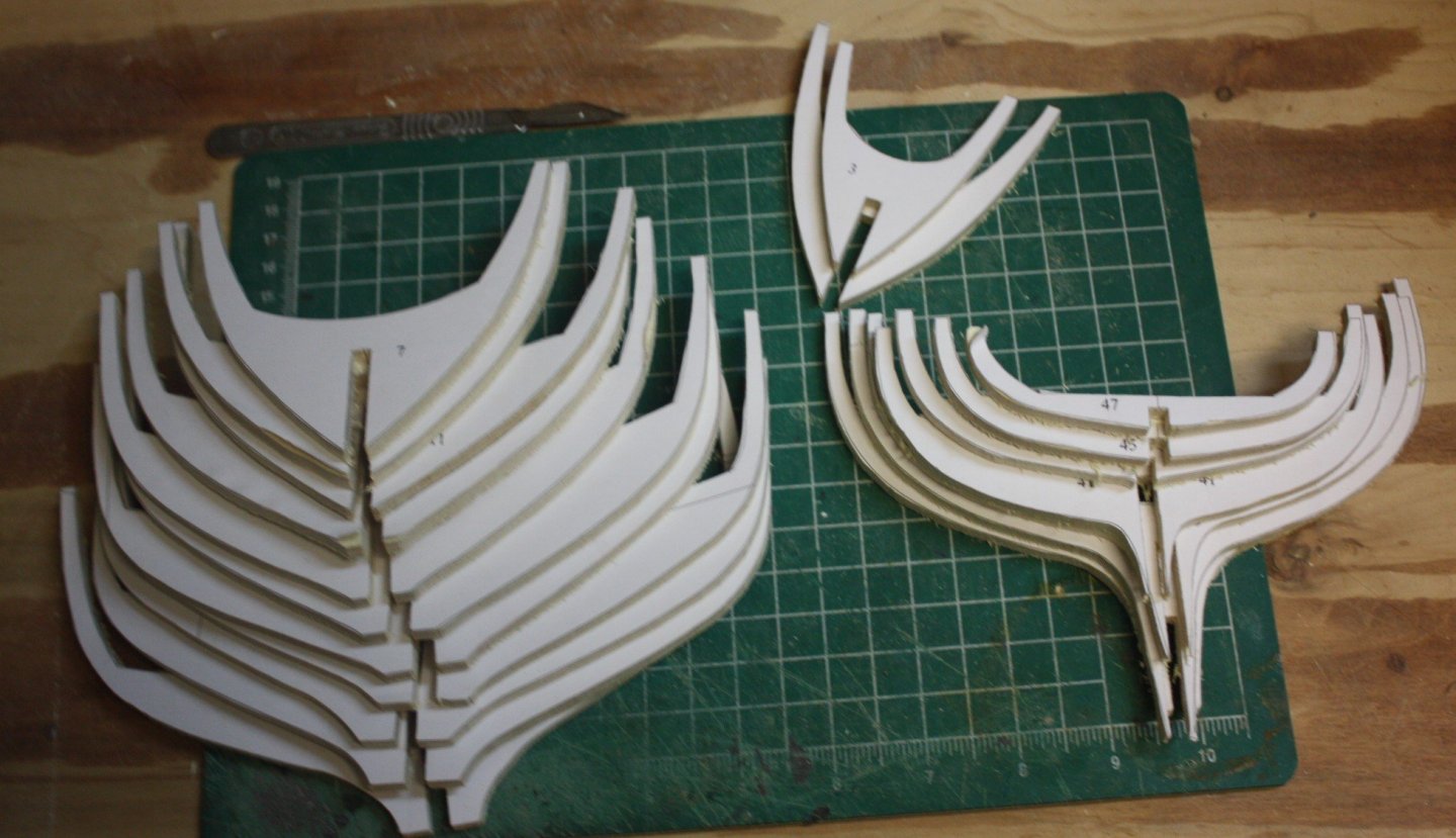
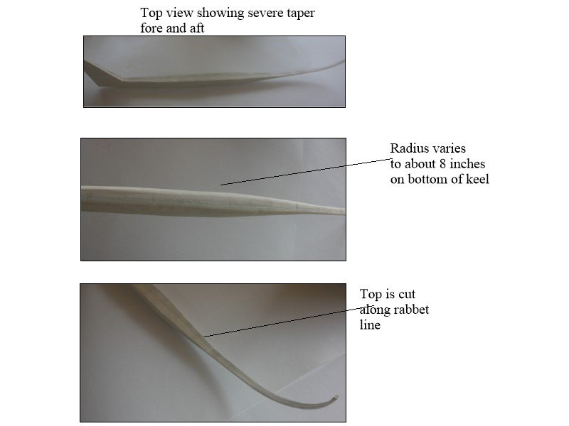
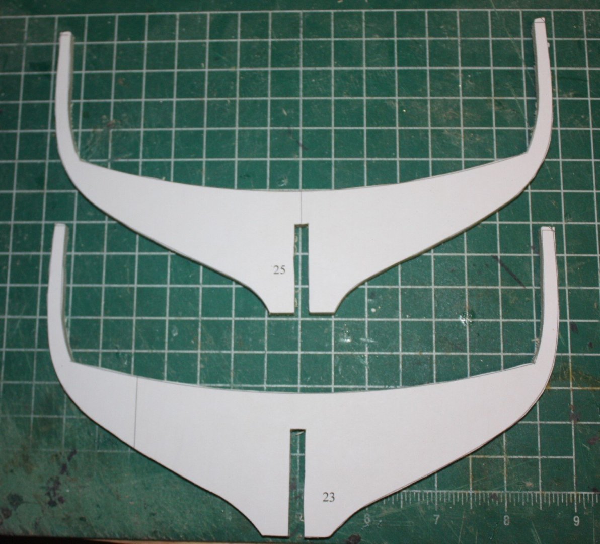
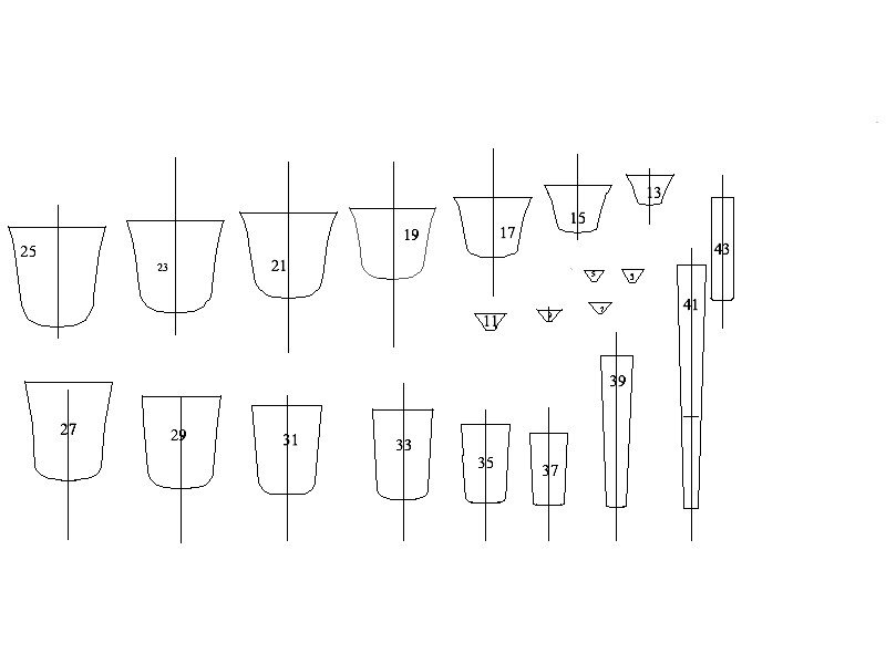
Past few weeks spent drawing up the frames and keel using the plans from the naval architect that designed her. The keel's design is unlike any I have seen before, having as much as an 8 inch radius on the bottom edges amidships and then reducing moving forward and aft. The taper from midships forward and aft is quite severe compared to keels in days of old and has been quite a challenge in fabricating it. The scale request is 1:24, so the max width of the keel is 1.1" at scale. I laminated two 3/4" pieces of poplar then ran it it through the planer on each side to the 1.1" dimension. From there I marked out the tapers and planed and sanded to the correct dimensions. Some finish sanding is still needed at this point. The keel cross section shape at each frame is being checked with templates made using the body plan drawing which shows the shape very nicely. There is a 20 foot section of the keel that is metal for ballast, but as the entire hull will be painted, there was no need to go casting this metal ballast piece. A false keel will be set on top of the keel and the frames glued in place on the false keel and keel. The frames are hybrids of bulkheads and true frames. A little of the inside of the hull will be viewable if the build goes as I have planned so full bulkheads did not seem like a good way to go. Photo of a couple of the frames are below as well as photos of the keel. The false keel and frames are made from 0.21" thick birch plywood. As a side note, when buying any lumber at a yard or home center. I am sure to check the actual thickness of any wood as it is not always as labelled. Allan Keel cross section template below
-
Two questions... Mast and rigging related.
allanyed replied to Jorge Hedges's topic in Masting, rigging and sails
Jorge, One more tool that is important. SHARP scissors and a SHARP nail clipper to snip the Irish pennant left over once a line is tied in place. I prefer scissors that have a blunt end. I was lucky to get a pair of Joewell professional hair shears at a trade show years ago for half price, and if not abused, should last my life time. Best line cutting tool I have ever used by far. Clippers are great, but if you have to reach into rigging at some point and snip a line, not so easy to maneuver around the lines as the clippers are short. For off the ship work as described above, clippers are a great choice and cheap. Allan -
Hi Dan, What year(s)? As with most things in naval architecture, there were changes in the construction of masts over time. Lees shows some drawings in The Masting and Rigging of English Ships of War that are from about 1640 to 1773, then other drawings as well as cross sections from 1773 to 1800, and another drawing with cross sections from after 1800 to 1860. The cross sections give a good view of the shapes of the cheeks, hounds and front fish. The main trunk is shown as a sold "pole", but the "pole" itself was also made in sections for at least larger diameter masts which he does not show. Page 161 in The Anatomy of Nelson's Ships by Longridge shows, in cross sections, the pieces used to construct a built mast for Victory, which is what I think you are looking for. He goes through more details with drawings for bibbs, cheeks, strops, rubbing paunch through page 170 as well. I am heading out with the guys for some fishing this weekend, but as you are a fellow Pittsburgh guy, if you wish, PM me with your email address and I can draw these sections up for you when I get back on Monday. Then again, if you do not bleed black and gold, the offer may be retracted. 🙃 Allan

-
Ronald, Photos would be a huge help here. Unless someone has the same kit, your description is really difficult to understand, for me at least. Allan
-
Stealers
allanyed replied to Sheerline's topic in Building, Framing, Planking and plating a ships hull and deck
THAT is the funniest thing I have heard in a few days. You should post it in Them Old Jokes in the Shore Leave forum here. Allan- 23 replies
-
- 1
-

-
- hms victory
- corel
- (and 1 more)
-
Stealers
allanyed replied to Sheerline's topic in Building, Framing, Planking and plating a ships hull and deck
Sheerline, the planking for your first build is really quite good. Study the tutorials and it will get even better! You get to spiling planks and pretty soon you may step over to the dark side of scratch building in the not too distant future! Allan- 23 replies
-
- 4
-
-
- hms victory
- corel
- (and 1 more)
-
Richard, choices of wire or rope have a lot to do with scale. I have always stropped with rope as was really done, but if you get to tiny scales such as those built by Lloyd Mcaffery and Donald McNarry wire may be the best way to go. McCaffery describes using nickel chromium wire for small diameters and brass wire for large diameters such as shrouds and stays. I think small and large in this case are relative terms for sure. He is specific about not using copper as it is too soft and pliable for lines that need to lie straight such as shrouds. Keep in mind this is for scales of 1:192 and smaller. (1"= 16 feet) He has built models at even smaller scales. My eyes strain and start tearing just thinking about these scales Allan
-
Stealers
allanyed replied to Sheerline's topic in Building, Framing, Planking and plating a ships hull and deck
Sheer, Your planking looks really good so far. You can indeed use stealers, but five does indeed seem like too many. Spiling would be the best solution for fitting the planks properly but your call on which way to go. Are you beveling the edges of each plank enough? There seems to be slight gap between strakes where there is a hard curve. ( I realize photos show up EVERYTHING that do not necessarily jump out when viewing our work live.) Sketch is attached to show what I mean about the bevel. Allan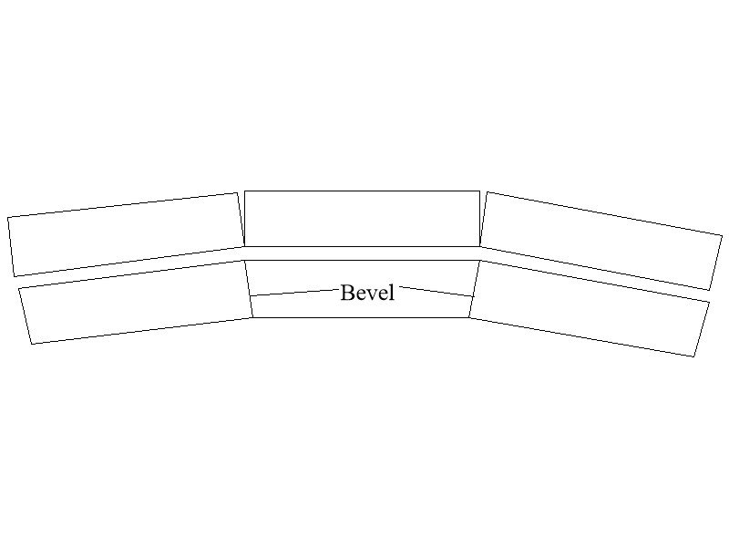
- 23 replies
-
- 3
-
-
- hms victory
- corel
- (and 1 more)
-
Richard, You can buy 1/4 pound spools of copper wire down to 40 gage (0.003") at McMaster Carr. For 32 gage (0.008), this is about 2000 foot and costs a little over $7 plus shipping. https://www.mcmaster.com/copper-wire/mirror-like-multipurpose-110-copper-wire/ They have a number of types of wire available. Allan
-
Welcome to MSW from another Floridian. PLEASE CHANGE YOUR SCREEN NAME TO SOMETHING OTHER THAN AN EMAIL ADDRESS AND DO NOT INCLUDE IT IN ANY POST. Members here can PM you which will go to your email. It would be great if you posted a little introduction on the new member page and give a short CV of yourself. Your sailors at 6 feet tall should be less than 3/4" high (0.70 inch would be about right) for 1:100 scale. Some members may be able to help you with a source. Ed Tosti, a member here, that authored books on Naiad and Young America made hundreds of soldiers before getting into ship modeling in a big way and when I saw his collection some years ago at his home I was in awe, so making your own is an option. Allan
-
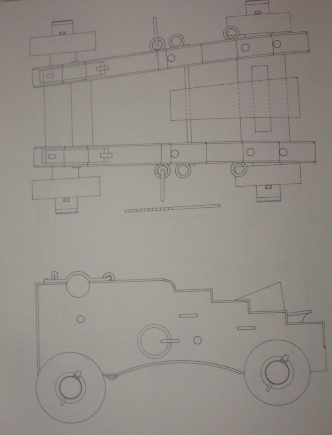
Thanks Mark, good catch !!! I agree the rings look light. Not sure who did the drawing but it is on page 378 in Volume II of The History of English Sea Ordinance. Drawings of earlier carriages in the same book show rings that appear to be a bit heavier so I have no idea if he was purposeful in showing the lighter weight rings or not. Allan
-
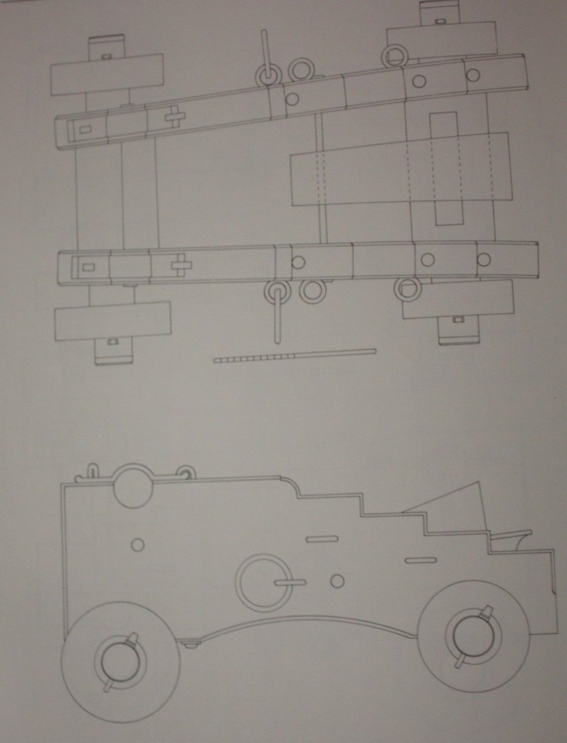
Richard, I don't know where the cross section is on your model, but keep in mind the Victory had 32 pounders, 24 pounders, and 12 pounders, so there may be differences in the block sizes. In addition, the 24 and 12 pounders would use pairs of single blocks where as the 32 pounders would use a double and single on each side of the carriage. I agree with Chuck that the eyes are hugely out of scale and should be replaced. Looking at carriage drawings in The History of English Sea Ordinance, the three eyes on each side of the carriage would be right at about 4 inches diameter for both the 24 and 32 pounders, slightly smaller for the 12 pounders. The ring on each side for the breech line would be about 8' diameter. I totally agree with Chuck, at this small scale, it is very difficult to make rings and such parts to scale. The following is a carriage from a 24 pounder of about 1790, and might help a little. Allan
-
Bulward Questioins
allanyed replied to shortgrass's topic in Building, Framing, Planking and plating a ships hull and deck
Shortgrass Can you post a photo or two showing the problem? Thanks Allan -
When to add cluelines, buntlines and sheets?
allanyed replied to rkwz's topic in Masting, rigging and sails
RK, I may be wrong, but I believe that when the vessels were dry docked, at least the spars and the upper masts as well as the appropriate rigging were taken down. I am sure there are those in the membership here that will have more details. If the ship was at anchor, the sails would be furled and secured at the spars, but the buntlines, et al would all be rigged. If you look at contemporary models, you will see many, if not all, have these lines rigged. Note that if they are rigged without sails, they are rigged in particular way. Yes, it is appropriate to include these lines, but in the end, the choice is yours. Allan -
I very much doubt that the straps are lead, but more likely some other soft metal. That said you can also use copper wire, silver solder it and blacken it with liver of sulfur. I prefer the liver of sulfur and copper, but do use a lot of brass then use Blacken It when necessary. Look at Ed Tostis, Young America log and he explains in detail the use of copper and liver of sulfur. If you want to actually make the straps as they were on the Greyhound, Blanford and others, according to the book on Blanford by Peter Goodwin, another 20 gun launched February 13, 1720 from the same yard as Greyhound, Deptford, and photos of other 20 gun 1719 Establishment ships at NMM you can buy thin copper or brass sheet and make them with this rather than wire. The same need for silver soldering and blackening will come into play. Allan
-
Chris is right, drill pilot holes a few thousandths smaller in diameter than the nails. Epoxy will hold up, but nailing is cleaner and a better way to go based on my experience. If the holes you drill are a tiny bit too large and the nails are not tight, a touch of Epoxy (or maybe CA) when you insert them will serve Allan
-
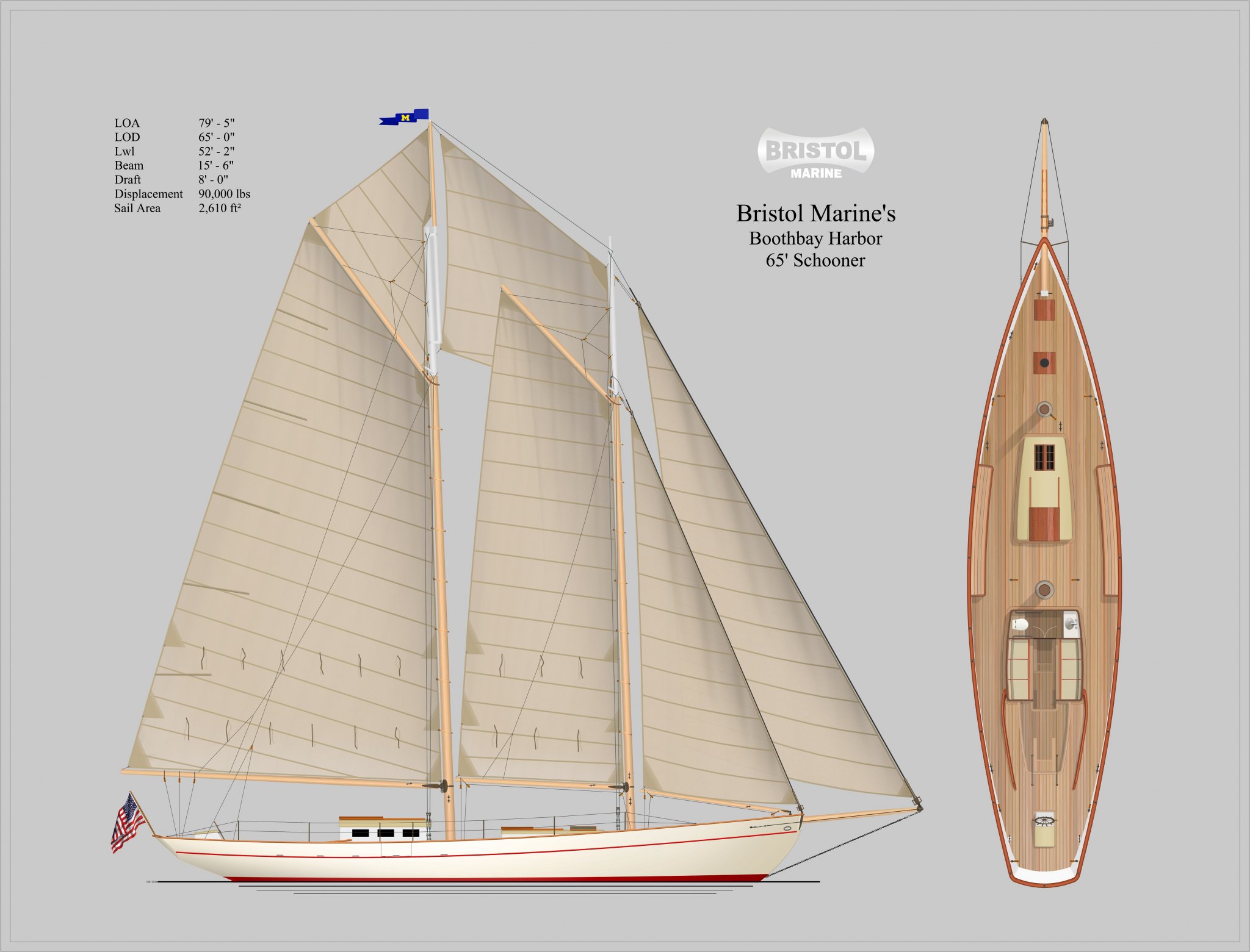
Bristol Marine has designed a new schooner, a Boothbay Harbor 65 that is yet to be built. They asked that I build a model which will be based on their detailed set of plans and their input on details as the build progresses. The vessel is unusual in that it is specifically designed with handicap access and is planned to be used for day sailing trips. They gave me permission to do a build log of the model and I will be starting the build shortly and hopefully will have updates on a regular basis. For now, I am posting below, with their permission, a drawing of the 65. Bristol Marine is the company which is restoring the Effie M. Morrisey (aka Ernestina). This opportunity to build the model came up as the result of an introduction to Bristol Marine by a very kind member here at MSW. Allan

-
C5 If you are asking for the MODEL's length of the masts what scale are you using? The plans are usually to some scale such as 1:48, 1:64 or some other, but not 1:1. As Chris asks, please let us know which vessel you are building, and maybe post a picture of the plans of the trestle tree that you mention. Welcome aboard!! Allan
-
Material for keel
allanyed replied to mikegr's topic in Building, Framing, Planking and plating a ships hull and deck
Mike, As this is a metal hull you could consider making a wooden plug of the hull, then using that as a mold to form a plastic hull. I recall seeing some fantastic hulls and other parts for that matter, of freighters and warships built in this way by a couple members of the NJ Ship Model Society 5 or 10 years ago. Hopefully there are some members here that can give you some information. I have made plugs, then used the plug to make a mold, then once cured, apply a mold release, then gelcoat, then fiberglass and resin to make the hulls. But for a one-off, it does not seem worth the time and expense compared to a plug former and hull made from a thermoplastic sheet. Allan -
How to narrow planks?
allanyed replied to Brewerpaul's topic in Building, Framing, Planking and plating a ships hull and deck
Mini planes are great for straight lines, but if you need a curve for a spiled plank or other reason, scalpel blades are the way to go. Xacto type are fine as are scalpel blades such as Swann Morton blades They are similarly priced at about US$27 to $29 for a 100 pack. One reason I switched to scalpels is the handle is not round and will not roll off the bench and stick in my leg or foot. Like a buttered piece of bread that is dropped always lands butter side down, Xacto knives fall blade first (in my experience anyway) I do like to use the Xacto handles for mini saw blades but much prefer scalpel blades to the Xacto blades as they seem to much sharper. The attached is a video I found this morning on the virtues of the both types of scalpel type cutters. Allan