
Check out our new MSW Sponsor Innocraftsman
×


allanyed
-
Posts
8,149 -
Joined
-
Last visited
Content Type
Profiles
Forums
Gallery
Events
Everything posted by allanyed
-

Endeavour Rigging Topmast Fore Preventor Stay
allanyed replied to Mr Pleasant's topic in Masting, rigging and sails
Hi Pleasant, The only thing I could find was in Lees' Masting and Rigging. The fore topmast stay did have a set of blocks as on your drawing. The stay rove through the bee on the starboard side of the sprit and had a double block seized in the end. The running part was as your drawing, but the only thing he mentions about belaying is that it is "made fast on the forecastle." The preventer would run through the bee on the port side as on the drawing and belay on the forecastle as well. Allan -
Cherry wood makes great furniture, but if you want a reddish color for planking, frames, or other parts of your model, Swiss (steamed) pear is a great way to go. It has no figuring and very small if any visible grain, holds an edge, carves and finishes well. Allan
-
Endeavour Rigging Topmast Fore Preventor Stay
allanyed replied to Mr Pleasant's topic in Masting, rigging and sails
Pleasant, Belated welcome to MSW. To the drawing, this does not look right. What are the rest of the words "repeated fore prev" ... ? On top of the sprit, the "S" looks to be deadeyes for the forestay and the deadeyes just forward of those are for the fore preventer stay. The line below could be a bobstay, but for Endeavor's time period, these would probably have been rigged with deadeyes, not blocks. Do the plans give a name to this line? Can you show the rest of the picture of the sprit. Assuming it is shown correctly, the running part of the line would have to run aft and secured possibly at a timber head or cleat. Again, welcome to MSW Allan -
Jeff, The reef tackle, throat halyard, and main sheets may very well have used a combination of both single and double blocks. I would be very surprised in no double blocks were used. Allan
-
Jaager I had this very conversation recently as it would be a second phase to the Scantlings of Royal Navy Ships. MOST of the contracts over a spread of a few years are virtually identical for a given rate once you get past the names of the builders, yard location and dates. It would likely only take a few contracts for each rate in any five or ten year period to have a pretty comprehensive set of contracts. You do have to be careful though as scantlings sometimes varied slightly from contract to contract. There are contracts for ships' boats as well which would be a nice thing to include. There are a lot of contracts for later ships in type face so much much easier to "interpret," but not nearly as much fun 😐 After 1718 the Establishments, Shipbuilder's Repository and Steel really say it all but I found there were definitely some small differences in contracts at those times compared to these sources. If I remember this correctly Mark P explained to me that there are not many, if any, contracts during the peace years as ships could pretty much all be built in Royal yards so the Establishments scantlings would be the information to follow if a model is from those peace years. I am sure he can enlighten all of us a bit more as he is truly an expert in this area. Allan
-
Making hooks and knees
allanyed replied to Brinkman's topic in Building, Framing, Planking and plating a ships hull and deck
I think Jaager has the right idea if you only need a few knees. Years ago I had visions of making lodging and hanging knees from branches pruned in a local apple orchard. No problem collecting hundreds of branches, but the cutting was not easy at scale so I gave up and used close grained (Castello boxwood) wood with no issues what so ever. If you go with the crooked pieces, pear or apple would be great, and again, with only a few to make, it could be fun little project. Problem right now is that they do not usually prune this time of year, but maybe a local orchard will have brush piles as did the one near me and as Jaager suggests. These would have pretty well dried wood. Do not use fresh cut unless you want to debark them then wait months for them to thoroughly dry. Allan -
Sorry Frank, I have not had the "pleasure" of transcribing any contracts prior to the 1690's, which is a fun filled hour or more (per page) I don't think that you can assume that because hooks and eyes are not mentioned, that they were bolted. Then again, no one can say the model builder had it wrong if there is no evidence otherwise. Allan
-
OcCre sanding block set
allanyed replied to LHsmith's topic in Modeling tools and Workshop Equipment
I am with Mark, you can make a variety of custom sized sanding sticks to meet your needs, from scrap wood, at no cost other than the sandpaper. Inside and outside radiuses are easily cut on a scroll saw or band saw. Soft holders are good for some surfaces to be sure, but not really necessary. I have a rubber block that I use on the hull for final sanding, otherwise, wooden sticks are better suited in many, if not most, cases because they can be custom sized. As to the finger nail sanding blocks, I tried these as well, but she was very upset when she went to look for hers and it was on my workbench. Be aware!! Allan -
Frank, If the bolts in the standards/knees go all the way through the bitts into the cross pieces, it seems to me it would defeat the purpose of easy removal. Just my thoughts though. Mark, Thank you, the drawing is a big help. Druxey, Great points all around thank you. Lived and learned, so was a good day! Allan
-
Hi Jaager, Thank you for your response. Sorry for any miscommunication, I was referring to the riding bitts not the jeer and sheet bitts. There were no belaying pins on the sheet and jeer bitts nor were there pin rails elsewhere, at least on British ships, from the 17th century. I posted a photo from a late 17th century model at NMM below as an example. The contract states that the stern and stem pieces were to be bolted with 1 1/8" bolts so I don't think making three foot long bolts was a problem as those were actually longer. You bring up a very good point when you mention bolts and nuts and rust as at that time, forelock bolts may have been used as well as threaded bolts with nuts due to corrosion problems (although a good coating of tar may have helped.) Then again, Vasa was found to have bolts and nuts used to a high degree. I agree that hooks and eyes would be easier if the cross timber had to be replaced, but how often would that happen, if ever? Maybe during a major overhaul or complete rebuild so I don't think that was the reason. The following is the complete paragraph from the contracts. Note that the spelling below is not mine, but is as found in the contracts. To place Two Pair of Substantiall Bitt Pinns The Aftermost Pair To be Sixteen Inches and the Foremost pair to be Fifteen Inches Square in the Head with Cross Peices to Each pair of the Same Dimentions. To Step them in Hold and to Place them abaft the Beame. To be Stopped with a score of an Inch Deep into the same and Bolted with Two Bolts in Each of an Inch Auger. To score the Crosspeices into the Bitts about Two Inches and to brace them together with Four pair of substantiall Iron Hookes and Eyes. To fix Two Pairs of good Standarts Upon Four Substantiall Carlings Placed between Beame and Beame in the Wake of them. The Fore and Aft Arme to be as long as the Bitt Pinns are in Distance and Bolt them with Five Bolts in Each Standart by an Inch and Eighth Auger. Frank, Thank you as well for your response. These ships were 48 gun fourth rates, and I believe the cross pieces were single pieces, albeit, very heavy. (700 pounds and more) Was the after wear that you mention from handling the anchor cable? I can see this, but it would only take place when handling the anchors and that was not so often. Was the wear that terrific to have to change these out very often? If that is the case, I would think that the hook and eye would not have gone out of favor and been replaced with bolting in place. Wear does seem to be the most logical reason though.
-
Makes sense Druxey, but I do wonder why the cross piece would be secured to the bitt pins with hooks and eyes rather than bolted. Possibly to more easily mend if struck by a cannon ball? Time to get out the WABAC machine again and visit the old master shipwrights for their take.

-
Welkom by MSW Andre. Allan
-
Goodwin gives details on how the bitt pins are mortised and the cross pieces bolted in place. He also shows a sketch of the cross pieces on the Foudroyant being secured to the bitts with hooks and eyes. The hook and eye method was apparently around for a long time as I found the following description in contracts for Severn and Burlington (contract dated 20 September 1695,) Colchester and Romney (contract dated 18 February 1693) and Jersey, (contract dated 31 July 1696) They all use the same wording. To score the Crosspeices into the Bitts about Two Inches and to brace them together with Four pair of substantiall Iron Hookes and Eyes. The contracts describe the bitt pins being bolted to the appropriate beams, but make no mention of the cross pieces being bolted to the pins, just the use of the hooks and eyes. As the cross timbers weighed about 750 pounds (single baulk of English oak, 15"X15" X 128") it would be a chore to remove it for any reason. My question is, unless damaged or worn out, why would it be removed? If it is not to be removed on a regular basis, why have the hook and eye rather than bolting them in place which is more secure and I believe was the more common practice, at least according to Goodwin. As all of the contracts are clear, I plan to use the hook and eye method in the model, but at least this enquiring mind would love to know why it would be used rather than being bolted. TIA Allan
-
Back in the late 70's, a friend and I were building Islander 32 yacht models from fiber glass. When it came time to make the non-skid patterns for the deck, I mixed powdered glass with paint. Masked off the pattern where the deck was to remain smooth, then painted the appropriate non-side areas with this mixture. Worked beautifully as it was consistent and did not look out of scale. Allan
-
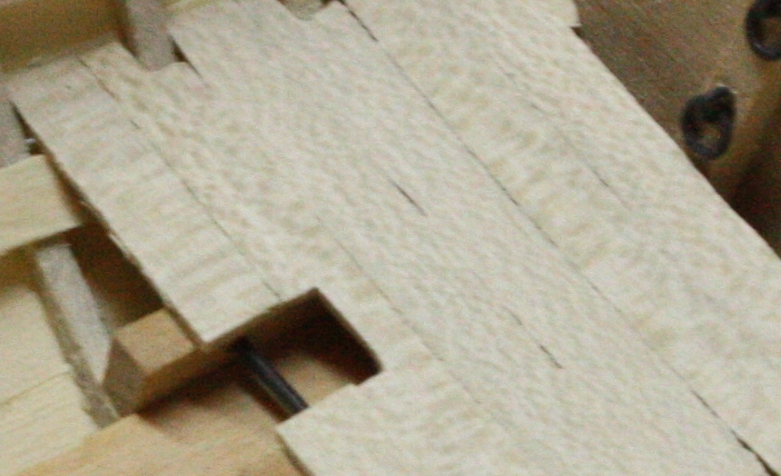
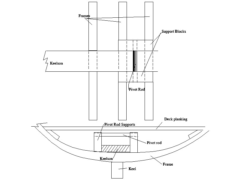
Vaddoc, I checked in Lavery's Arming and Fitting as he has a lot of information on ships' boats, but only mentions which boats had davits for lifting the buoy rope of the anchors. It SEEMS the davit would be of sufficient weight that there would just be a slot in the bottom to rest on the iron pivot rod. What year is given on the NMM drawing that you are using? In reading up on the yawls, I saw that there were a lot of changes in their design and whether they were clinker or carvel built depending on the year.
-
Matiz, I am very impressed with your start on Euryalus and will follow your build as she is so close to my heart. For many years I have been lucky to be in Milano and Firenze for work several times each year, but of course now that is not possible. If I ever get back to Toscana, I would love to sip a grappa or two with you and discuss this great hobby of ours. Ciao Allan
-
Vaddoc, If you look in the Boats of Men of War, on page 35 there is an engraving by J.A. Anderson published in 1807 "getting up of a kedge anchor" using the davit. W. E. May mentions in the caption that the boat is similar to a 21 foot yawl longboat found on a sixth rate. You can also find this engraving at the RMG Collections site. https://collections.rmg.co.uk/collections/objects/111915.html I have some doubt that a capstan would ever be used on a ship's boat. The left photo in your post may be similar to the way the anchor was raised off the bottom in the engraving. The right hand photo is a thirty foot launch with a windlass which was mortised for hand spikes for getting up an anchor, but I did not include the hand spikes when I took the photo. Allan
-
You raise the bar higher and higher with each new series of photos. GREAT work including the photos!! I dare say, your patience level must be in the stratosphere, never settling for less. Allan
-
Drilling brass post to install railing.
allanyed replied to Kevin Kenny's topic in Metal Work, Soldering and Metal Fittings
VERY WELL DONE!!!! Thank you very much for sharing this, it very useful. I have a question regarding your shorter rails. (If you already posted this, my apologies.) How do you make the "bump" in the stanchions where the rail passes through? Allan -
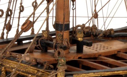
As to nautical terms, the learning curve has been a long one (at least for me) and still, some new terms pop up now and again. If you have a chance, read some of the contracts from the late 17th and early 18th centuries and there will be a slew of terms to deal with, if only because of the odd spellings compared to today. Keep in mind the ring around the mast is not a cover or ring at all so maybe easier to make it the way it actually was, that is, a series of wedges to hold the mast tight to the partners. Then again either way you go, it should be finished as Wefalck mentioned, with a canvas cover. Thick grayish paint serves well to replicate the canvas so you would not see the seams of the wedges "wedged" together around the mast. The best reason to try to the mill though is to get in some practice!! Allan
-
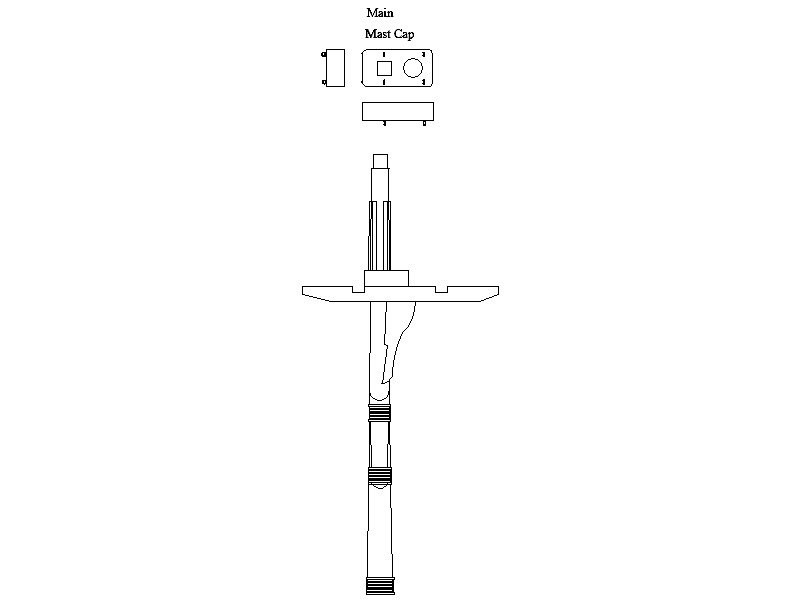
Glenn, I think there may be some misunderstanding of what you call a mast cap. You mention it is on the deck. The mast cap is at the top of the mast, and is usually rectangular with rounded corners, has a square hole for the lower mast top and a round hole for the lower part of the mast above it to pass through. It sounds like you are looking to make a ring instead of a ring of wedges at the mast partners where the mast passes between the deck beams, or in POB, between bulkheads. Can you post a sketch and confirm this is for your current build for Cheerful. Below is a sketch showing the top of a mast and the mast cap. If you are looking to make a ring, a lathe might be easier than using the milling machine. Allan
-
Hull building
allanyed replied to mauryd824's topic in Building, Framing, Planking and plating a ships hull and deck
Maury, It sounds like the model is plank on bulkhead, is that the case? If yes, filling the space between the frames before planking is common and very good practice. Even so, when planking, following the tutorials is STRONGLY RECOMMENDED as the way to go. It is not as difficult as it may appear and it will avoid ruining the model. Just laying the strake of planking without spiling or tapering and pre-bending to shape will have the planks buckle. Or, to avoid that, the planking would have to be laid down in an unrealistic pattern and even so, could still be problematic with the buckling issue. Ship modeling is not quick and easy, nor do I think it was ever meant to be. Quick and easy is not synonymous with satisfactory in this case, and more than likely would yield something totally unsatisfactory. There are no rules, but this is just meant as some food for thought based on more than a few years of personal experience. Allan -
This model would be impressive at 1:48. It is doubly so at this small scale. I will be following your build more closely now as it gives me hope in the possibilities of small scale builds. Allan
-
MONTAÑES by Amalio
allanyed replied to Amalio's topic in - Build logs for subjects built 1751 - 1800
The bar has been set SOOOO high by your build. If you ever decide to go into a new field such as surgery, I would trust you and your scalpel totally. Allan -
Toni, If you are going to buy copper wire, get spools and cut pieces to length. FAR cheaper. I bought four different sizes in a box which each spool being 100 feet long. You can find all kinds of diameters and spool sizes to meet your needs. The one that worked for me is https://www.amazon.com/Copper-Round-Assorted-24-26-28-30-Spool/dp/B07D54TM1G/ref=sr_1_12?dchild=1&keywords=copper+wire+spool+stl&qid=1594460184&sr=8-12 Allan
